The Meaning of Redundancy - 3D Topology and … Meaning of Redundancy – 3D Topology and Geometric...
13
TS XX – Title of the session (e.g. TS 1 – Standards) The Meaning of Redundancy – 3D Topology and Geometric Representation Integrating the Generations FIG Working Week 2008 Stockholm, Sweden 14-19 June 2008 1/13 The Meaning of Redundancy - 3D Topology and Geometric Parameterization Key words: 3D, data modeling, redundancy, adjustment, BIM SUMMARY Database normalization is a standard technique to ensure data integrity. Explicitly specified 3D topology as well ensures geometric consistency. This article explains a stepwise reduction of redundancy in the 3D data model. Whereas the topological normalization is well discussed in literature the geometric normalization is a subject to recent research. This approach of data normalization is motivated by the need for applying geodetic adjustment techniques to measured (observed) three-dimensional building models. The article examines different usage of the term redundancy and then shows up the normalization of the “polygon soup” data model to an almost redundant free data model. In contrast to existing CAD or GIS data models, the discussed approach does not use any coordinates, instead it utilizes normal vectors to planes. Using this approach, the number of unknowns is significantly reduced, resulting in fewer measurements to be observed. The primary reason for normalization is not to reduce the amount of data being stored but rather to ensure consistency and to allow suitable geometric generalization. In addition efficient adjustment techniques can be applied.
Transcript of The Meaning of Redundancy - 3D Topology and … Meaning of Redundancy – 3D Topology and Geometric...

TS XX – Title of the session (e.g. TS 1 – Standards)
The Meaning of Redundancy – 3D Topology and Geometric Representation
Integrating the Generations
FIG Working Week 2008
Stockholm, Sweden 14-19 June 2008
1/13
The Meaning of Redundancy
- 3D Topology and Geometric Parameterization
Key words: 3D, data modeling, redundancy, adjustment, BIM
SUMMARY
Database normalization is a standard technique to ensure data integrity. Explicitly specified
3D topology as well ensures geometric consistency. This article explains a stepwise reduction
of redundancy in the 3D data model. Whereas the topological normalization is well discussed
in literature the geometric normalization is a subject to recent research. This approach of data
normalization is motivated by the need for applying geodetic adjustment techniques to
measured (observed) three-dimensional building models.
The article examines different usage of the term redundancy and then shows up the
normalization of the “polygon soup” data model to an almost redundant free data model. In
contrast to existing CAD or GIS data models, the discussed approach does not use any
coordinates, instead it utilizes normal vectors to planes. Using this approach, the number of
unknowns is significantly reduced, resulting in fewer measurements to be observed. The
primary reason for normalization is not to reduce the amount of data being stored but rather to
ensure consistency and to allow suitable geometric generalization. In addition efficient
adjustment techniques can be applied.
TS XX – Title of the session (e.g. TS 1 – Standards)
The Meaning of Redundancy – 3D Topology and Geometric Representation
Integrating the Generations
FIG Working Week 2008
Stockholm, Sweden 14-19 June 2008
2/13
The Meaning of Redundancy - 3D Topology and Geometric
Parameterization
1. INTRODUCTION
Gathering three dimensional geometric data of buildings is becoming increasingly important.
Virtual 3D City Models and Building Information Models require reliable information about
the inside of buildings. Traditional surveying techniques, such as tacheometry, are too time
consuming and too expensive. This paper shows how to parameterize the three-dimensional
building geometry in a non-standard form that is suitable for fast data acquisition by making
use of least squares adjustment. In contrast to existing CAD or GIS data models, the
discussed approach does not use any coordinates, instead it utilizes normal vectors to planes.
Using this approach, the number of unknowns is significantly reduced, resulting in fewer
measurements to be observed.
This article discusses certain aspects of a conceptual three-dimensional data model that was
introduced by [Gielsdorf and Gründig 2002]. The methodology of this promising model relies
on three main Ideas. Topological and geometrical data are specified separately. Explicit
topology is compulsory. Secondly, geometry is parameterized with flat surfaces not
coordinates. And thirdly, the observations (measurement, relative geometry) are stored in the
project database and are used to determine the parameters of the absolute geometry by
applying geodetic adjustment techniques.
This model does not end in itself. The explicit specification of a 3D topology facilitates
consistency checks during insert, update or delete operation. A surface based parameterization
reduces the number of unknown parameters in the adjustment, by shifting information, like
planarity of a face, from the computational geometry domain to the relational domain.
[Thompson and Oosterom 2008] emphasis a soaring paradigm: “Note that there is a trend in
which the original observations and measurements are more often stored in the (cadastral)
database, in addition to the resulting interpretations (parcels)”.
This article discusses the methodology of normalization in the problem domain of 3D geo-
and building information. Normalization reduces redundancy. The primary reason for
normalization is not to reduce the amount of data being stored but rather to ensure consistency
and to allow suitable geometric generalization.
2. REDUNDANCY
If “pieces of information” are exceeding what is necessary or normal, these pieces are called
redundant. Redundancy is characterized by similarity or repetition. The meaning of the word
ranges from pure duplication of critical components of an engineering system, to ”wasted”
space used to transmit certain data, including tautology in spoken language. (Wikipedia)
The GIS/Surveying world uses the term ”redundancy” in context of SDBMS (Spatial
Database Management Systems) and in the context of Adjustment Calculation. Database

TS XX – Title of the session (e.g. TS 1 – Standards)
The Meaning of Redundancy – 3D Topology and Geometric Representation
Integrating the Generations
FIG Working Week 2008
Stockholm, Sweden 14-19 June 2008
3/13
designer try to avoid redundancy. Database Normalization minimizes duplication of
information in order to ensure data integrity when data is inserted, updated or deleted.
Empirical science like Engineering Surveying, Photogrammetry and Geodesy try to obtain
redundant observations in order to increase precision and reliability. The different connotation
- negative connotation on the database side and positive connotation on the surveying side -
result from different types of information.
A database usually represents Deterministic Information (DI). The model of the world does
not involve uncertainty and errors. This assumption leads to a contradiction free
representation of the real world. Deterministic variables should be stored only once. Here,
redundancy means duplication of identical information.
Models from Measurements are realized with Stochastic Information (SI). Due to the inherent
stochastic properties of observations the model involves information about precision and
correlation of all parameters. Although diverse observations are used to describe the same
quantity in the real world, every observation is stored, since every measurement is a subject to
errors or mistakes. Here redundancy can be considered as statistical degree of freedom
[Mikhail 1976]. Any surveying engineering application benefits from the usage of redundant
information by estimating precision and reliability.
This article describes how the reduction of deterministic redundancy leads to a data model
that supports input, update and deletion of three-dimensional topologic-geometric data and
supports redundant measurement. Since the amount of unknown variables is lessened this
allows for efficient algorithms concerning stochastic information (adjustment calculation).
3. 3D TOPOLOGY IN SPATIAL DATAMODELS
3.1 Topological Models
In spatial information models the terms “geometry” and “topology” are closely linked. From
the mathematical point of view the three-dimensional Euclidian space is a topological
space.
In context of solid modeling and GIS, geometric information describes position, orientation
and shape of objects whereas topology describes relationships between objects. Topologic
properties are invariant under certain geometric transformation.
This article discusses some aspects of explicit topological boundary representation of three-
dimensional solids. Out of scope are: Topological predicates from a result of geometric
operations and topological networks used for routing.
[Mäntylä 1988] substantiates the necessity of a topological model with the following
properties of the Euclidian space : The domain of the propertyset (x,y,z) of the metric space
is infinit, uncountable and open. It is imposible to map all points of this space in a
unstructured way. The structure of space decomposition (voxel, TEN, B-Rep, Half-Space...) is
called topology.

TS XX – Title of the session (e.g. TS 1 – Standards)
The Meaning of Redundancy – 3D Topology and Geometric Representation
Integrating the Generations
FIG Working Week 2008
Stockholm, Sweden 14-19 June 2008
4/13
[Mäntylä 1988] distinguishes three separate levels of modeling:
Fig. 1 A three-level view of modeling [Mäntylä 1988]
Physical objects (terrain, buildings, streets, tunnels, parcels) must be identified and the
universe of discourse must be restricted, since the real world cannot be mapped in full detail.
Mathematical objects are a suitable idealizations of the real-world physical objects. Diverse
mathematical approaches are discussed in literature (regular cell decomposition, TEN, B-Rep,
CSG). [Zlatanova 2004] gives an overview on the history of data models and recent
developments. Less effort has been made on the problem of digital representations. Only
recently [Thompson 2007] addresses the finite precision of spatial data.
Since there is no way to find an explicit representation of shapes in space an indirect
method has to be found. The implicit representation of infinite point-sets can be structured in
following classes:
Decomposition models. The point set is represented as a collection of simple objects from a
fixed collection of primitive object types with a single (!) implicit or explicit ”gluing”
operation. Example for decomposition models are: Voxel, Octree, binary space subdivision.
Constructive models. The point set is represented as a combination of primitive point sets
together with general construction operations. Example for constructive models are: Boolean
set operations on half spaces, constructive solid geometry (CSG).
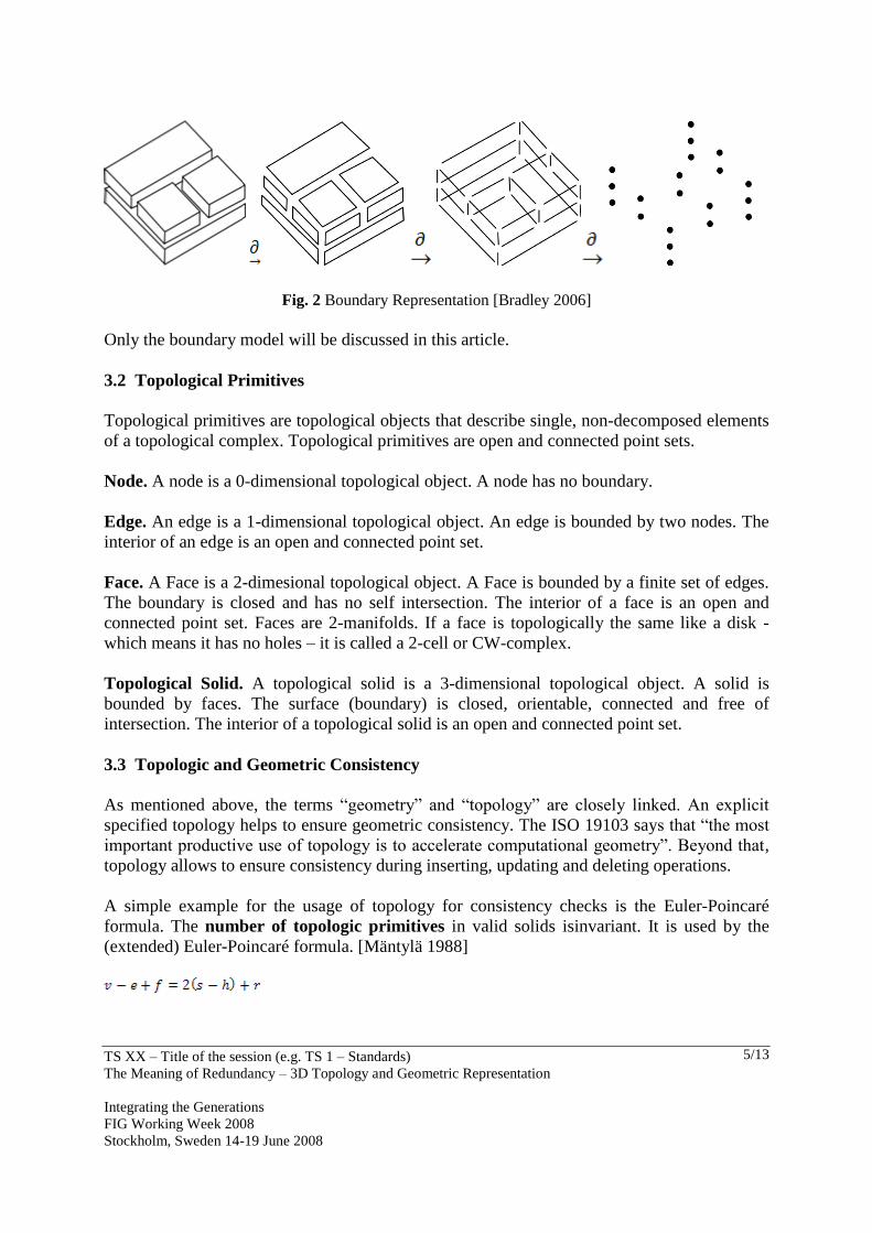
Boundary models. These vector based models decompose the 3d solid with the relation type
”boundary“ . Complex -dimesional Shapes are described indirectly with their -
dimensional boundary. Topology then is the structure that spezifies how objects of lower
dimension are combined.
TS XX – Title of the session (e.g. TS 1 – Standards)
The Meaning of Redundancy – 3D Topology and Geometric Representation
Integrating the Generations
FIG Working Week 2008
Stockholm, Sweden 14-19 June 2008
5/13
Fig. 2 Boundary Representation [Bradley 2006]
Only the boundary model will be discussed in this article.
3.2 Topological Primitives
Topological primitives are topological objects that describe single, non-decomposed elements
of a topological complex. Topological primitives are open and connected point sets.
Node. A node is a 0-dimensional topological object. A node has no boundary.
Edge. An edge is a 1-dimensional topological object. An edge is bounded by two nodes. The
interior of an edge is an open and connected point set.
Face. A Face is a 2-dimesional topological object. A Face is bounded by a finite set of edges.
The boundary is closed and has no self intersection. The interior of a face is an open and
connected point set. Faces are 2-manifolds. If a face is topologically the same like a disk -
which means it has no holes – it is called a 2-cell or CW-complex.
Topological Solid. A topological solid is a 3-dimensional topological object. A solid is
bounded by faces. The surface (boundary) is closed, orientable, connected and free of
intersection. The interior of a topological solid is an open and connected point set.
3.3 Topologic and Geometric Consistency
As mentioned above, the terms “geometry” and “topology” are closely linked. An explicit
specified topology helps to ensure geometric consistency. The ISO 19103 says that “the most
important productive use of topology is to accelerate computational geometry”. Beyond that,
topology allows to ensure consistency during inserting, updating and deleting operations.
A simple example for the usage of topology for consistency checks is the Euler-Poincaré
formula. The number of topologic primitives in valid solids isinvariant. It is used by the
(extended) Euler-Poincaré formula. [Mäntylä 1988]

TS XX – Title of the session (e.g. TS 1 – Standards)
The Meaning of Redundancy – 3D Topology and Geometric Representation
Integrating the Generations
FIG Working Week 2008
Stockholm, Sweden 14-19 June 2008
6/13
In addition to the check of nodes, edges, faces and solids this simple formula controls the
number of rings (hole in a face) and shells.
The referential integrity of topologic primitives ensures that the boundary resp. the interior
of a topological primitive exit in the model instance. For instance: It can be checked, whether
an edge that is supposed to bound a specific face really exists.
Cardinality between topologic primitives provides another validation rule. An edge is
bounded by exactly two nodes. A mesh is bounded by three edges or more. In linear models a
solid is at least bounded by four faces.
Topologic Integrity of a ring is ensured if the ring is closed (first vertex equals last vertex)
and if distinct vertices are used.
Geometric Integrity validates whether all vertices are in the same the plane and whether
edges are non-intersecting. If faces have additional interior inner boundaries (holes) these
rings have to lie in the same plane like the exterior ring, and the interior rings are not allowed
to intersect and must follow the orientation rules of the data model. Furthermore interior rings
must not overlap nor intersect nor touch the exterior ring.
In general one can state, that the algorithms for validating geometric integrity are more
expensive than those that are ensured by the data model or the DBMS. Topological encoding
transfers certain algorithms from computational geometry to combinatorial algorithms which
are well supported by relational data bases.
4. TOPOLOGICAL NORMALIZATION
In terms of relational databases “normalization” means the reduction of multiple stored pieces
of information. This chapter does not provide a new 3D topological data model. The aim is to
describe the stepwise reduction of redundancy. One technique though is to replace composite
relationship (black rhomb) with a shared aggregate (white rhomb).
In so-called “topology-free”, “polygon soup” or “spaghetti” data models faces are represented
as a collection of coordinate triples (x,y,z). The coordinate values are stored in every
collection as a point composite.
This simple structure is suitable to visualization purposes, since there is no need for searching
during rendering. It is obvious, that the storage of the point coordinates is redundant.
However, more levels of redundancy can be specified [Fig 3]:
– Node-redundancy (multiple storage of point geometry)
– Edge-redundancy (multiple storage of node-connectivity (edge))
– Face-redundancy (multiple storage of edge-connectivity (face) )

TS XX – Title of the session (e.g. TS 1 – Standards)
The Meaning of Redundancy – 3D Topology and Geometric Representation
Integrating the Generations
FIG Working Week 2008
Stockholm, Sweden 14-19 June 2008
7/13
– Solid-redundancy (multiple storage of faces)
– Fig. 3 Levels of redundancy
In order to avoid node-redundancy points are uniquely stored in an independent list and are
referred by faces. (shared point aggregation).
Here every vertex-coordinate is only stored once. As a next step of normalization the entity
type ”edge” is introduced, in order to avoid edge-redundancy. Since the ”normalization” of
higher-dimensions redundancies must take into account the orientation of the topological
primitives, the 2:N relationship is specified more detailed with the attributes ”start” and
”end”.
Now a face consists of a list of oriented edges and is stored twice. By switching from edge-
composition to edge-aggregation a ”real-world” edge is only stored once, but is refered by
two faces (if the model is a 2-manyfold). Since these two faces refer the same edge, but might
be of different orientation, the edge is decomposed in two half edges. A half-edge is entity
with a binary orientation flag and a reference to an edge.
TS XX – Title of the session (e.g. TS 1 – Standards)
The Meaning of Redundancy – 3D Topology and Geometric Representation
Integrating the Generations
FIG Working Week 2008
Stockholm, Sweden 14-19 June 2008
8/13
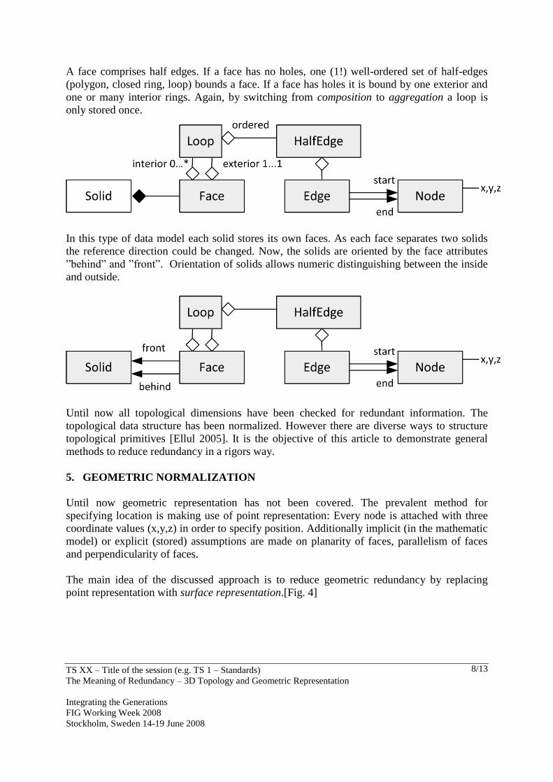
A face comprises half edges. If a face has no holes, one (1!) well-ordered set of half-edges
(polygon, closed ring, loop) bounds a face. If a face has holes it is bound by one exterior and
one or many interior rings. Again, by switching from composition to aggregation a loop is
only stored once.
In this type of data model each solid stores its own faces. As each face separates two solids
the reference direction could be changed. Now, the solids are oriented by the face attributes
”behind” and ”front”. Orientation of solids allows numeric distinguishing between the inside
and outside.
Until now all topological dimensions have been checked for redundant information. The
topological data structure has been normalized. However there are diverse ways to structure
topological primitives [Ellul 2005]. It is the objective of this article to demonstrate general
methods to reduce redundancy in a rigors way.
5. GEOMETRIC NORMALIZATION
Until now geometric representation has not been covered. The prevalent method for
specifying location is making use of point representation: Every node is attached with three
coordinate values (x,y,z) in order to specify position. Additionally implicit (in the mathematic
model) or explicit (stored) assumptions are made on planarity of faces, parallelism of faces
and perpendicularity of faces.
The main idea of the discussed approach is to reduce geometric redundancy by replacing
point representation with surface representation.[Fig. 4]

TS XX – Title of the session (e.g. TS 1 – Standards)
The Meaning of Redundancy – 3D Topology and Geometric Representation
Integrating the Generations
FIG Working Week 2008
Stockholm, Sweden 14-19 June 2008
9/13
Fig. 4 a) point representation b) surface representation c) plane intersection
A flat surface is represented by its normal vector , ,
T
x y zn n n n and the orthogonal
(shortest) distance d to the origin. Since topology is integral part of the data model the
(relational) database is able to determine which planes intersect in each node. The point
coordinates can be calculated on demand, using Cramer’s Rule.
Fig. 5 Planar faces and paralell planes
How does this shift from point representation to surface representation affect the objective to
reduce geometric redundancy?
Planarity of a single face. Planarity of polygons is traditionally seen as a geometric integrity
constrained and is checked with run time algorithms up to a certain tolerance. Planarity must
be ensured for computational reasons (computational geometry) or visualization purposes.
Especially manmade objects are designed with planar surfaces. Using surface representation
(here: plane based) the discussed model ensures the planarity of a single polygon by means of
referential integrity.
Planarity of faces. The Face-Plane relationship is of cardinality 1:N. Each face associates
exactly one plane. But many faces can associate the same plane. Faces representing the floor,
the ceiling or the façade could link the same geometrical entity “plane”. Planarity of different
faces is ensured by referential integrity.
TS XX – Title of the session (e.g. TS 1 – Standards)
The Meaning of Redundancy – 3D Topology and Geometric Representation
Integrating the Generations
FIG Working Week 2008
Stockholm, Sweden 14-19 June 2008
10/13
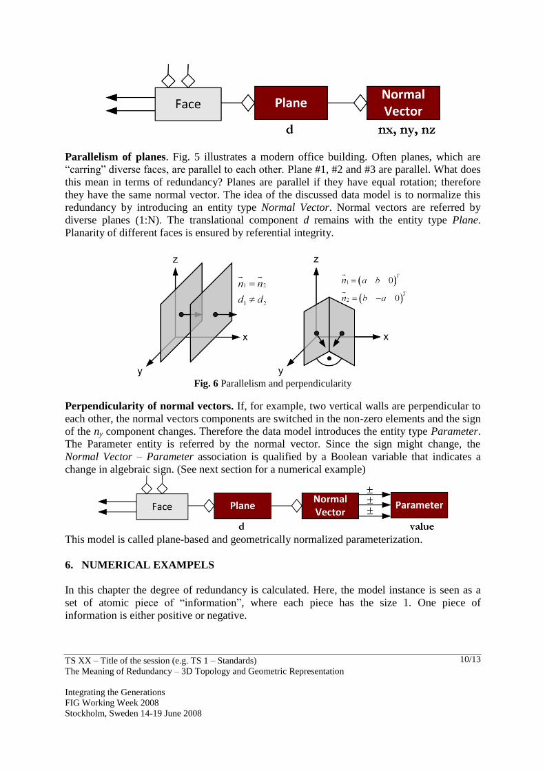
Parallelism of planes. Fig. 5 illustrates a modern office building. Often planes, which are
“carring” diverse faces, are parallel to each other. Plane #1, #2 and #3 are parallel. What does
this mean in terms of redundancy? Planes are parallel if they have equal rotation; therefore
they have the same normal vector. The idea of the discussed data model is to normalize this
redundancy by introducing an entity type Normal Vector. Normal vectors are referred by
diverse planes (1:N). The translational component d remains with the entity type Plane.
Planarity of different faces is ensured by referential integrity.
Fig. 6 Parallelism and perpendicularity
Perpendicularity of normal vectors. If, for example, two vertical walls are perpendicular to
each other, the normal vectors components are switched in the non-zero elements and the sign
of the ny component changes. Therefore the data model introduces the entity type Parameter.
The Parameter entity is referred by the normal vector. Since the sign might change, the
Normal Vector – Parameter association is qualified by a Boolean variable that indicates a
change in algebraic sign. (See next section for a numerical example)
This model is called plane-based and geometrically normalized parameterization.
6. NUMERICAL EXAMPELS
In this chapter the degree of redundancy is calculated. Here, the model instance is seen as a
set of atomic piece of “information”, where each piece has the size 1. One piece of
information is either positive or negative.
TS XX – Title of the session (e.g. TS 1 – Standards)
The Meaning of Redundancy – 3D Topology and Geometric Representation
Integrating the Generations
FIG Working Week 2008
Stockholm, Sweden 14-19 June 2008
11/13
In terms of deterministic information a positive piece needs to be stored whereas a negative
piece needs to be checked. The total sum of information equals zero when all data are
checked. In terms of stochastic information (i.e. Least-Squares-Adjustment) a positive piece
is one unknown whereas a negative piece is one condition. The total sum of information
equals zero when the so called minimal configuration is present.
6.1 Cube
Point aggregate. A cube needs 9 pieces of information (3 Translation, 3 Rotation, 3
Dimensions). With point representation 8 points have to be stored. Since each point has 3
components this equals 24 pieces of information. Thus the overhead of information
(redundancy) can be calculated with 24-9=15. This means, that 15 consistency checks have to
be made. These are:
– Planarity of faces (-6)
– Parallelism of opposite faces. Normal vector dot product equals -1 (-3)
– Perpendicularity of pairs of parallel faces (-3)
– Orientation of faces (inside or outside) (-3)
Normalized to Parallelism of Planes. 3 normal vectors need to be stored if the cardinality
plane-normal vector is 1:N. 6 translational components d must be attached to each plane. So
the number of stored values is 3*3 + 6 = 15. There still is a redundancy of 6. So 6 negative
pieces of information need to be specified:
– Absolute value of the 3 normal vectors equals 1 (-3)
– Perpendicularity of all three normal vectors (-3)
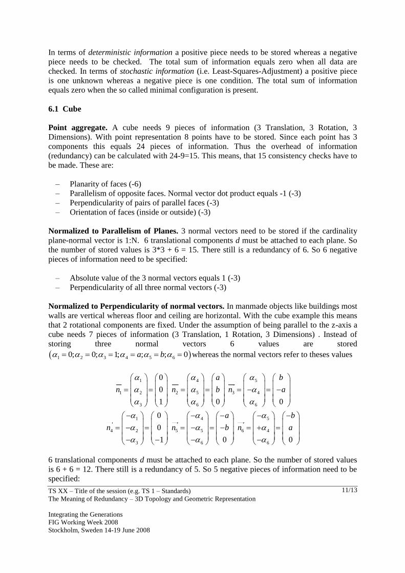
Normalized to Perpendicularity of normal vectors. In manmade objects like buildings most
walls are vertical whereas floor and ceiling are horizontal. With the cube example this means
that 2 rotational components are fixed. Under the assumption of being parallel to the z-axis a
cube needs 7 pieces of information (3 Translation, 1 Rotation, 3 Dimensions) . Instead of
storing three normal vectors 6 values are stored
1 2 3 4 5 60; 0; 1; ; ; 0a b whereas the normal vectors refer to theses values
1
1 2
3
0
0
1
n
4
2 5
6 0
a
n b
5
3 4
6 0
b
n a
1
4 2
3
0
0
1
n
4
5 5
6 0
a
n b
5
6 4
6 0
b
n a
6 translational components d must be attached to each plane. So the number of stored values
is 6 + 6 = 12. There still is a redundancy of 5. So 5 negative pieces of information need to be
specified:
TS XX – Title of the session (e.g. TS 1 – Standards)
The Meaning of Redundancy – 3D Topology and Geometric Representation
Integrating the Generations
FIG Working Week 2008
Stockholm, Sweden 14-19 June 2008
12/13
– 1 2 3 6, , , are fixed (-4)
– a,b are rotation parameters so a²+b² = 1 (-1)
Even with this very simple example of a cube one can find many ways of parameterization.
The decision, which type of parameterization is applied, depends on the application.
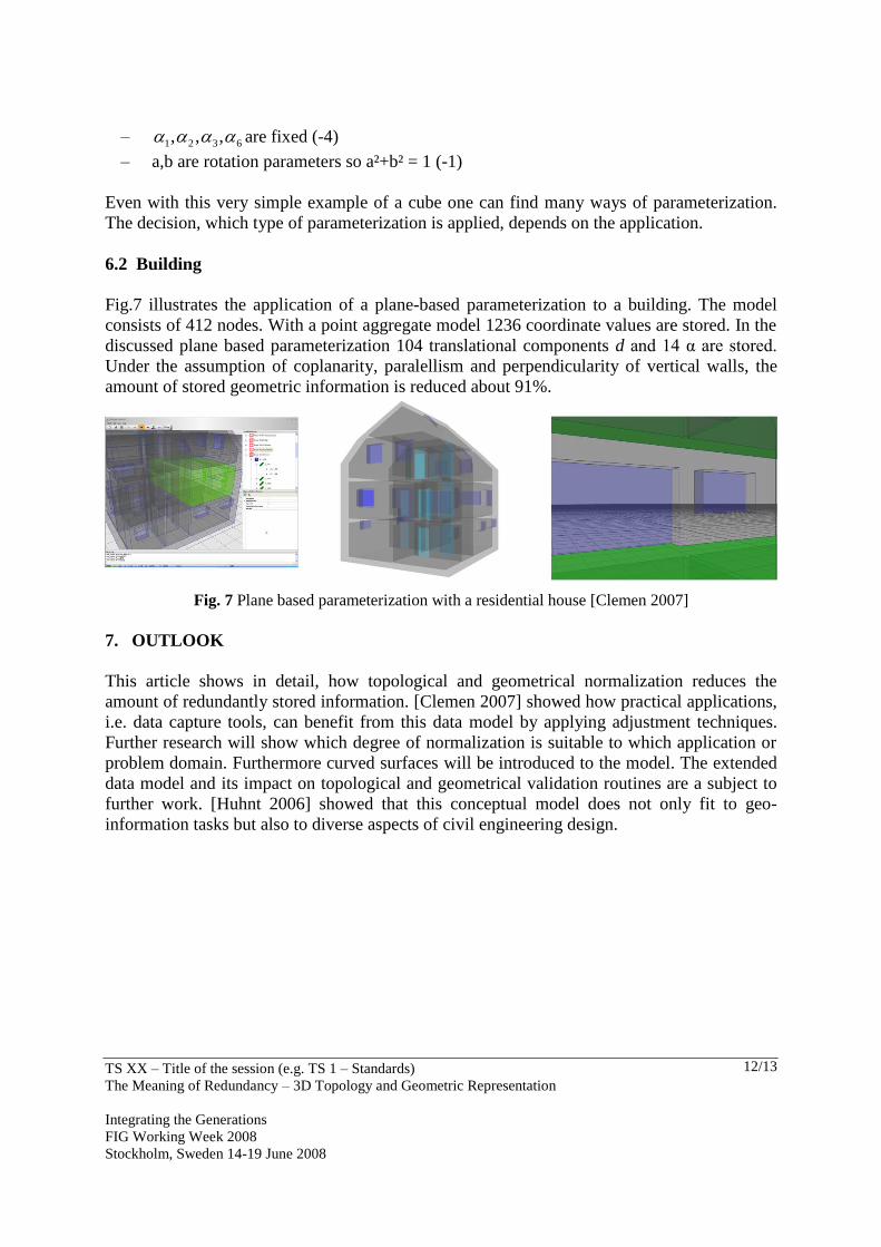
6.2 Building
Fig.7 illustrates the application of a plane-based parameterization to a building. The model
consists of 412 nodes. With a point aggregate model 1236 coordinate values are stored. In the
discussed plane based parameterization 104 translational components d and 14 α are stored.
Under the assumption of coplanarity, paralellism and perpendicularity of vertical walls, the
amount of stored geometric information is reduced about 91%.
Fig. 7 Plane based parameterization with a residential house [Clemen 2007]
7. OUTLOOK
This article shows in detail, how topological and geometrical normalization reduces the
amount of redundantly stored information. [Clemen 2007] showed how practical applications,
i.e. data capture tools, can benefit from this data model by applying adjustment techniques.
Further research will show which degree of normalization is suitable to which application or
problem domain. Furthermore curved surfaces will be introduced to the model. The extended
data model and its impact on topological and geometrical validation routines are a subject to
further work. [Huhnt 2006] showed that this conceptual model does not only fit to geo-
information tasks but also to diverse aspects of civil engineering design.

TS XX – Title of the session (e.g. TS 1 – Standards)
The Meaning of Redundancy – 3D Topology and Geometric Representation
Integrating the Generations
FIG Working Week 2008
Stockholm, Sweden 14-19 June 2008
13/13
REFERENCES
[Bradley 2006] http://ww1.mathematik.uni-karlsruhe.de/~bradley/Arch/Archkomp/
[Clemen 2007] Clemen, C. and Gründig, L. 2007, The IMAP principle in Building
Information Systems, In: Proceedings of XXX FIG Working Week 2007, Hong Kong,
China
[Ellul 2005] Ellul,C., et. al. , 2005, A Generic Topological Data Structure for 3D Data. In:
Topology and Spatial Databases Workshop. Glasgow, UK
[Huhnt 2006] Huhnt, W. and Gielsdorf, F., 2006, Topological Information as Leading
Information in Building Product Models, In: Proceedings of 17th International
Conference on the Applications of Computer Science and Mathematics in Architecture
and Civil Engineering, Weimar, Germany
[Gründig and Gielsdorf 2002] Gründig L., Gielsdorf F. : Geometrical Modeling for Facility
Managment Systems Applying Surface Parameter, in: XXII FIG Federation
Internationale des Geometres Congress, Washington D.C., USA
[Mäntylä 1988] Mäntylä M.,1988, Solid Modeling, Computer Science Press, Rockville, USA
[Mikhail 1976] Mikhail,E., 1976, Observation and Least Squares, University Press of
America, Lanham-New York-London
[Thompson 2007] Thompson, R. ,2007, Towards a Rigorous Logic for Spatial Data
Representation, PhD Thesis, TU Delft, Netherlands
[Thompson and Oosterom 2008] Thompson, R. and Oosterom, P. van. 2008. Mathematically
provable correct implementation of integrated 2D and 3D representations, in:
Advances in 3D Geoinforamtion Systems. Springer. Berlin
[Zlatanova 2004] Zlatanova, S., et. al, 2004, Topological models and frameworks for 3D
spatial objects, In: Journal of Computers & Geosciences, May, Vol. 30, No. 4, 2004