The master failure curve of pipe steels and crack paths in ...
8
The master failure curve of pipe steels and crack paths in connection with hydrogen embrittlement A. Elazzizi a , M. Hadj Meliani b,c,* , A. Khelil b , G. Pluvinage c , Y.G. Matvienko d a Depart. of Mechanics, Faculty of Mechanics, USTO University, Algeria b LPTPM, FT, Hassiba BenBouali University of Chlef, 02000 Chlef, Algeria c LaBPS-ENIM, Paul Verlaine University of Metz, Ile de Saulcy 57045, France d Mechanical Engineering Research Institute of the Russian Academy of Sciences, 4 M. Kharitonievsky Per., 101990 Moscow, Russia article info Article history: Received 19 October 2013 Received in revised form 6 November 2014 Accepted 10 December 2014 Available online 7 January 2015 Keywords: Master failure curve Notch Hydrogen embrittlement abstract This paper provides some critical review of the history and state of two elastic fracture mechanics (K and T) and relationship to crack paths. A particular attention is given in the case of hydrogen embrittlement. A fracture toughness transferability curve (K rc eT ef ) has been established for the X52 pipe steels described by a linear relationship where T ef is the average value of T stress over the characteristic length of the fracture process. A mechanism involving influence of the T ef ;c -stress on void growth for ductile failure is proposed; the ef- fects of hydrogen on crack paths from the viewpoint of microstructural aspects are disputed. Copyright © 2014, Hydrogen Energy Publications, LLC. Published by Elsevier Ltd. All rights reserved. Introduction Fracture toughness is now considered as not intrinsic to ma- terial but depends on geometry, thickness, loading mode and more generally to constraint. Recent numerical and experi- mental studies have attempted to describe fracture in terms of two or three fracture parameters [1e3]. The elastic stress fields in a region surrounding the crack tip can be characterized by the following solution [1]: s ij ¼ K I ffiffiffiffiffiffiffiffi 2pr p f ij ðqÞþ Td xi d xj þ A 3 ffiffiffiffiffiffiffiffi 2pr p þ 0ðrÞ (1) where K I is the stress intensity factor, f ij (q) is the angular function, d ij is the symbol of Kronecker's determinant. A polar coordinate system (r,q) with origin at crack tip is used. Several methods have been proposed in literature to determine the T- stress for cracked specimen. The stress difference method has been proposed by Yang et al. [4]. It was noted [5e8] that T- stress, which is the non-singular linear elastic stress compo- nent parallel to the crack, characterizes the local crack tip stress field for elastic linear material, and the elastic plastic material with the restriction of small-scale yielding condi- tions. Various studies have shown that T-stress has signifi- cant influence on fracture toughness, crack growth direction, A 3 has some influence crack stability [9e15]. The KeT and KeA 3 approaches lead to a two-parameter fracture criterion. With K as the driving force and T or A 3 a constraint parameters, a master failure curve can be suc- cessfully used to take into account the constraints of stress * Corresponding author. LPTPM, FT, Hassiba BenBouali University of Chlef, 02000 Chlef, Algeria. E-mail address: [email protected] (M. Hadj Meliani). Available online at www.sciencedirect.com ScienceDirect journal homepage: www.elsevier.com/locate/he international journal of hydrogen energy 40 (2015) 2295 e2302 http://dx.doi.org/10.1016/j.ijhydene.2014.12.040 0360-3199/Copyright © 2014, Hydrogen Energy Publications, LLC. Published by Elsevier Ltd. All rights reserved.
Transcript of The master failure curve of pipe steels and crack paths in ...
ww.sciencedirect.com
i n t e r n a t i o n a l j o u r n a l o f h y d r o g e n en e r g y 4 0 ( 2 0 1 5 ) 2 2 9 5e2 3 0 2
Available online at w
ScienceDirect
journal homepage: www.elsevier .com/locate/he
The master failure curve of pipe steels and crackpaths in connection with hydrogen embrittlement
A. Elazzizi a, M. Hadj Meliani b,c,*, A. Khelil b, G. Pluvinage c,Y.G. Matvienko d
a Depart. of Mechanics, Faculty of Mechanics, USTO University, Algeriab LPTPM, FT, Hassiba BenBouali University of Chlef, 02000 Chlef, Algeriac LaBPS-ENIM, Paul Verlaine University of Metz, Ile de Saulcy 57045, Franced Mechanical Engineering Research Institute of the Russian Academy of Sciences, 4 M. Kharitonievsky Per.,
101990 Moscow, Russia
a r t i c l e i n f o
Article history:
Received 19 October 2013
Received in revised form
6 November 2014
Accepted 10 December 2014
Available online 7 January 2015
Keywords:
Master failure curve
Notch
Hydrogen embrittlement
* Corresponding author. LPTPM, FT, HassibaE-mail address: [email protected] (M
http://dx.doi.org/10.1016/j.ijhydene.2014.12.00360-3199/Copyright © 2014, Hydrogen Ener
a b s t r a c t
This paper provides some critical review of the history and state of two elastic fracture
mechanics (K and T) and relationship to crack paths. A particular attention is given in the
case of hydrogen embrittlement. A fracture toughness transferability curve (KrceTef) has
been established for the X52 pipe steels described by a linear relationship where Tef is the
average value of T stress over the characteristic length of the fracture process. Amechanism
involving influence of the Tef ;c-stress on void growth for ductile failure is proposed; the ef-
fects of hydrogen on crack paths from the viewpoint ofmicrostructural aspects are disputed.
Copyright © 2014, Hydrogen Energy Publications, LLC. Published by Elsevier Ltd. All rights
reserved.
Introduction
Fracture toughness is now considered as not intrinsic to ma-
terial but depends on geometry, thickness, loading mode and
more generally to constraint. Recent numerical and experi-
mental studies have attempted to describe fracture in terms of
two or three fracture parameters [1e3]. The elastic stress fields
in a region surrounding the crack tip can be characterized by
the following solution [1]:
sij ¼ KIffiffiffiffiffiffiffiffi2pr
p fijðqÞ þ Tdxidxj þA3
ffiffiffiffiffiffiffiffi2pr
pþ 0ðrÞ (1)
where KI is the stress intensity factor, fij(q) is the angular
function, dijis the symbol of Kronecker's determinant. A polar
BenBouali University of C. Hadj Meliani).40gy Publications, LLC. Publ
coordinate system (r,q) with origin at crack tip is used. Several
methods have been proposed in literature to determine the T-
stress for cracked specimen. The stress differencemethod has
been proposed by Yang et al. [4]. It was noted [5e8] that T-
stress, which is the non-singular linear elastic stress compo-
nent parallel to the crack, characterizes the local crack tip
stress field for elastic linear material, and the elastic plastic
material with the restriction of small-scale yielding condi-
tions. Various studies have shown that T-stress has signifi-
cant influence on fracture toughness, crack growth direction,
A3 has some influence crack stability [9e15].
The KeT and KeA3 approaches lead to a two-parameter
fracture criterion. With K as the driving force and T or A3 a
constraint parameters, a master failure curve can be suc-
cessfully used to take into account the constraints of stress
hlef, 02000 Chlef, Algeria.
ished by Elsevier Ltd. All rights reserved.
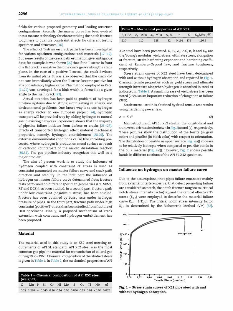
Table 2 e Mechanical properties of API X52.
E, GPA sY, MPa su, MPa A, % n K KIcMPaffiffiffiffiffim
p
210 410 528 32 0.164 876 116.6
i n t e rn a t i o n a l j o u r n a l o f h y d r o g e n en e r g y 4 0 ( 2 0 1 5 ) 2 2 9 5e2 3 0 22296
fields for various proposed geometry and loading structure
configurations. Recently, the master curve has been evolved
into amature technology for characterizing the notch fracture
toughness to quantify constraint effects for different testing
specimen and structures [16].
The effect of T-stress on crack paths has been investigated
for various specimen configurations and materials [17e19].
But some results of the crack path estimation give ambiguous
data; for example, it was shown [20] that if the T-stress in front
of a flat crack is negative then the crack grows along the crack
plane. In the case of a positive T-stress, the crack deviates
from its initial plane. It was also observed that the crack did
not turn immediately when the T-stress became positive but
at a considerably higher value. The method employed in Refs.
[21,22] was developed for a kink which is formed at a given
angle to the main crack [23].
Actual attention has been paid to problem of hydrogen
pipeline systems due to strong world asking in energy and
environmental problems. One future way is to use hydrogen
as energy vector. In one European project [24], hydrogen
transport will be provided way by adding hydrogen to natural
gas in existing networks. Experience shows that the majority
of pipeline failure initiates from defects or cracks [25e27].
Effects of transported hydrogen affect material mechanical
properties, namely, hydrogen embrittlement [28,29]. The
external environmental conditions cause free corroding pro-
cesses, where hydrogen is product on metal surface as result
of cathodic counterpart of the anodic dissolution reaction
[30,31]. The gas pipeline industry recognizes this well as a
major problem.
The aim of present work is to study the influence of
hydrogen coupled with constraint (T stress is used as
constraint parameter) on master failure curve and crack path
direction and stability. In the first part the influence of
hydrogen on master failure curve determined from fracture
tests performed on different specimen geometries (CT, SENT,
RT and DCB) has been studied. In a second part, fracture path
under low constraint (negative T-stress) has been studied.
Fracture has been obtained by burst tests under hydrogen
pressure of pipes. In the third part, fracture path under high
constraint (positive T-stress) has been studied from fracture of
DCB specimens. Finally, a proposed mechanism of crack
extension with constraint and hydrogen embrittlement has
been proposed.
Material
The material used in this study is an X52 steel meeting re-
quirements of API 5L standard. API X52 steel was the most
common gas pipeline material for transmission of oil and gas
during 1950e1960. Chemical composition of the studied steels
is given in Table 1. In Table 2, themechanical properties of API
Table 1 e Chemical composition of API X52 steel(weight%).
C Mn P Si Cr Ni Mo S Cu Ti Nb Al
0.22 1.220 e 0.240 0.16 0.14 0.06 0.036 0.19 0.04 <0.05 0.032
X52 steel have been presented. E, sY, su, A%, n, k and KIc are
the Young's modulus, yield stress, ultimate stress, elongation
at fracture, strain hardening exponent and hardening coeffi-
cient of RambergeOsgood law, and fracture toughness,
respectively.
Stress strain curves of X52 steel have been determined
with and without hydrogen absorption and reported in Fig. 1.
Classical tensile properties such as yield stress and ultimate
strength increases also when hydrogen is absorbed in steel as
indicated in Table 2. A small increase of yield stress has been
noted (2.5%) as an important reduction of elongation at failure
(38%).
Static stressestrain is obtained by fitted tensile test results
using hardening power law:
s ¼ K$εn (2)
Microstructure of API 5L X52 steel in the longitudinal and
transverseorientation is showninFig. 2(a) and (b), respectively.
These pictures show the distribution of the ferrite (in gray
color) and pearlite (in black color) with respect to orientation.
The distribution of pearlite in upper surface (Fig. 2(a)) appears
to be relatively isotropic when compared to pearlite bands in
the bulk material (Fig. 2(c)). However, Fig. 2 shows pearlite
bands in different sections of the API 5L X52 specimen.
Influence on hydrogen on master failure curve
Due to the assumptions, that pipes failure emanates mainly
from external interferences i.e. that defect promoting failure
are considered as notch, the notch fracture toughness (critical
notch stress intensity factor) Kr;cand the critical effective T-
stress (Tef ;c) were employed to describe the material failure
curve Kr;c ¼ fðTef ;cÞ. The critical notch stress intensity factor
Kr;c is determined by the Volumetric Method (VM) [32].
Fig. 1 e Stress strain curves of X52 pipe steel with and
without hydrogen absorption.
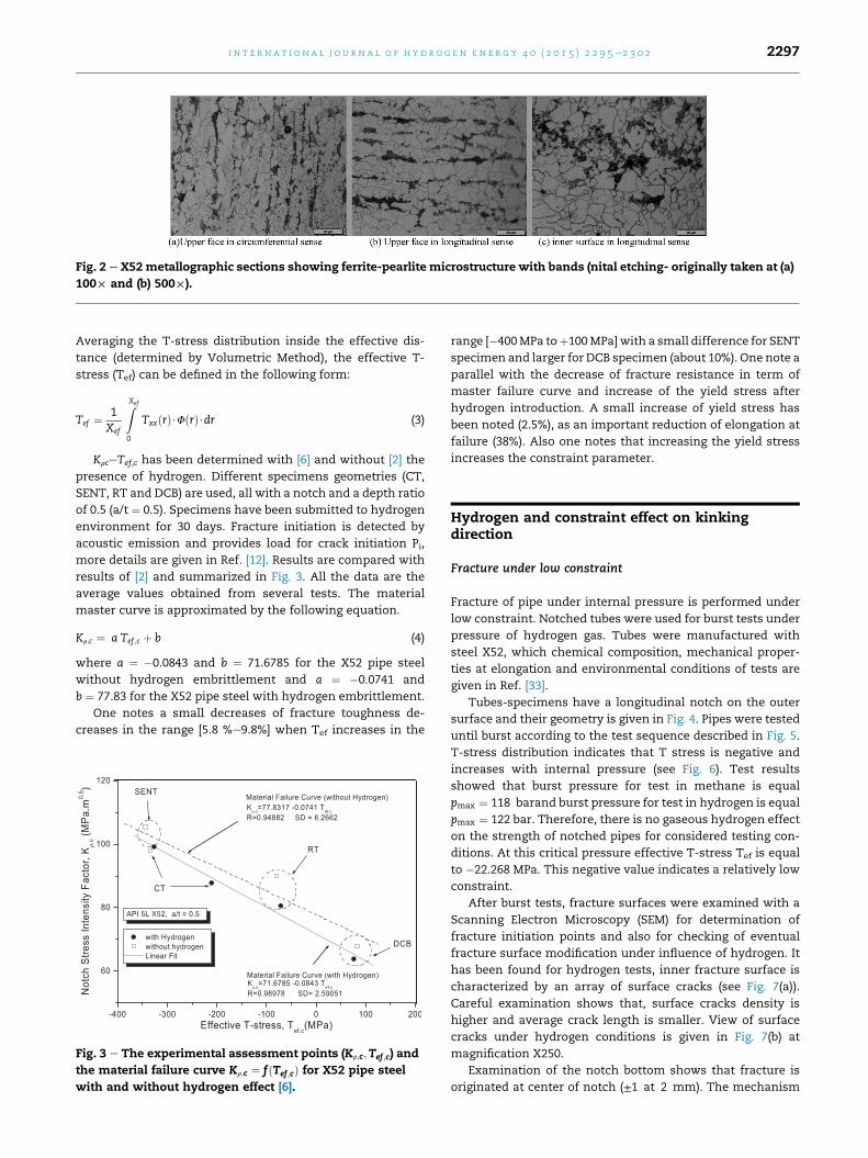
Fig. 2 e X52metallographic sections showing ferrite-pearlite microstructure with bands (nital etching- originally taken at (a)
100£ and (b) 500£).
i n t e r n a t i o n a l j o u r n a l o f h y d r o g e n en e r g y 4 0 ( 2 0 1 5 ) 2 2 9 5e2 3 0 2 2297
Averaging the T-stress distribution inside the effective dis-
tance (determined by Volumetric Method), the effective T-
stress (Tef) can be defined in the following form:
Tef ¼ 1Xef
ZXef
0
TxxðrÞ$FðrÞ$dr (3)
KrceTef,c has been determined with [6] and without [2] the
presence of hydrogen. Different specimens geometries (CT,
SENT, RT and DCB) are used, all with a notch and a depth ratio
of 0.5 (a/t ¼ 0.5). Specimens have been submitted to hydrogen
environment for 30 days. Fracture initiation is detected by
acoustic emission and provides load for crack initiation Pi,
more details are given in Ref. [12]. Results are compared with
results of [2] and summarized in Fig. 3. All the data are the
average values obtained from several tests. The material
master curve is approximated by the following equation.
Kr;c ¼ a Tef ;c þ b (4)
where a ¼ �0.0843 and b ¼ 71.6785 for the X52 pipe steel
without hydrogen embrittlement and a ¼ �0.0741 and
b ¼ 77.83 for the X52 pipe steel with hydrogen embrittlement.
One notes a small decreases of fracture toughness de-
creases in the range [5.8 %e9.8%] when Tef increases in the
Fig. 3 e The experimental assessment points (Kr;c;Tef ;c) and
the material failure curve Kr;c ¼ fðTef ;cÞ for X52 pipe steel
with and without hydrogen effect [6].
range [�400MPa toþ100MPa]with a small difference for SENT
specimen and larger for DCB specimen (about 10%). One note a
parallel with the decrease of fracture resistance in term of
master failure curve and increase of the yield stress after
hydrogen introduction. A small increase of yield stress has
been noted (2.5%), as an important reduction of elongation at
failure (38%). Also one notes that increasing the yield stress
increases the constraint parameter.
Hydrogen and constraint effect on kinkingdirection
Fracture under low constraint
Fracture of pipe under internal pressure is performed under
low constraint. Notched tubes were used for burst tests under
pressure of hydrogen gas. Tubes were manufactured with
steel X52, which chemical composition, mechanical proper-
ties at elongation and environmental conditions of tests are
given in Ref. [33].
Tubes-specimens have a longitudinal notch on the outer
surface and their geometry is given in Fig. 4. Pipes were tested
until burst according to the test sequence described in Fig. 5.
T-stress distribution indicates that T stress is negative and
increases with internal pressure (see Fig. 6). Test results
showed that burst pressure for test in methane is equal
pmax ¼ 118 barand burst pressure for test in hydrogen is equal
pmax ¼ 122 bar. Therefore, there is no gaseous hydrogen effect
on the strength of notched pipes for considered testing con-
ditions. At this critical pressure effective T-stress Tef is equal
to �22.268 MPa. This negative value indicates a relatively low
constraint.
After burst tests, fracture surfaces were examined with a
Scanning Electron Microscopy (SEM) for determination of
fracture initiation points and also for checking of eventual
fracture surface modification under influence of hydrogen. It
has been found for hydrogen tests, inner fracture surface is
characterized by an array of surface cracks (see Fig. 7(a)).
Careful examination shows that, surface cracks density is
higher and average crack length is smaller. View of surface
cracks under hydrogen conditions is given in Fig. 7(b) at
magnification X250.
Examination of the notch bottom shows that fracture is
originated at center of notch (±1 at 2 mm). The mechanism
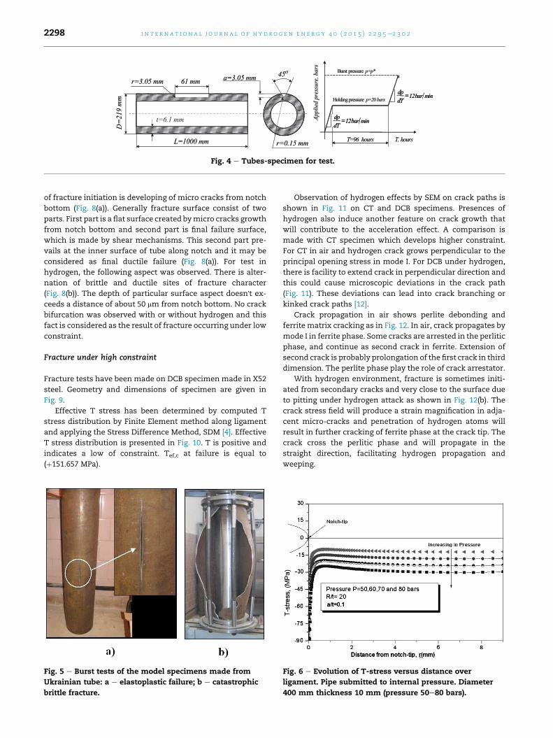
Fig. 4 e Tubes-specimen for test.
i n t e rn a t i o n a l j o u r n a l o f h y d r o g e n en e r g y 4 0 ( 2 0 1 5 ) 2 2 9 5e2 3 0 22298
of fracture initiation is developing of micro cracks from notch
bottom (Fig. 8(a)). Generally fracture surface consist of two
parts. First part is a flat surface created bymicro cracks growth
from notch bottom and second part is final failure surface,
which is made by shear mechanisms. This second part pre-
vails at the inner surface of tube along notch and it may be
considered as final ductile failure (Fig. 8(a)). For test in
hydrogen, the following aspect was observed. There is alter-
nation of brittle and ductile sites of fracture character
(Fig. 8(b)). The depth of particular surface aspect doesn't ex-
ceeds a distance of about 50 mm from notch bottom. No crack
bifurcation was observed with or without hydrogen and this
fact is considered as the result of fracture occurring under low
constraint.
Fracture under high constraint
Fracture tests have been made on DCB specimen made in X52
steel. Geometry and dimensions of specimen are given in
Fig. 9.
Effective T stress has been determined by computed T
stress distribution by Finite Element method along ligament
and applying the Stress Difference Method, SDM [4]. Effective
T stress distribution is presented in Fig. 10. T is positive and
indicates a low of constraint. Tef,c at failure is equal to
(þ151.657 MPa).
Fig. 5 e Burst tests of the model specimens made from
Ukrainian tube: a e elastoplastic failure; b e catastrophic
brittle fracture.
Observation of hydrogen effects by SEM on crack paths is
shown in Fig. 11 on CT and DCB specimens. Presences of
hydrogen also induce another feature on crack growth that
will contribute to the acceleration effect. A comparison is
made with CT specimen which develops higher constraint.
For CT in air and hydrogen crack grows perpendicular to the
principal opening stress in mode I. For DCB under hydrogen,
there is facility to extend crack in perpendicular direction and
this could cause microscopic deviations in the crack path
(Fig. 11). These deviations can lead into crack branching or
kinked crack paths [12].
Crack propagation in air shows perlite debonding and
ferrite matrix cracking as in Fig. 12. In air, crack propagates by
mode I in ferrite phase. Some cracks are arrested in the perlitic
phase, and continue as second crack in ferrite. Extension of
second crack is probably prolongation of the first crack in third
dimension. The perlite phase play the role of crack arrestator.
With hydrogen environment, fracture is sometimes initi-
ated from secondary cracks and very close to the surface due
to pitting under hydrogen attack as shown in Fig. 12(b). The
crack stress field will produce a strain magnification in adja-
cent micro-cracks and penetration of hydrogen atoms will
result in further cracking of ferrite phase at the crack tip. The
crack cross the perlitic phase and will propagate in the
straight direction, facilitating hydrogen propagation and
weeping.
Fig. 6 e Evolution of T-stress versus distance over
ligament. Pipe submitted to internal pressure. Diameter
400 mm thickness 10 mm (pressure 50e80 bars).
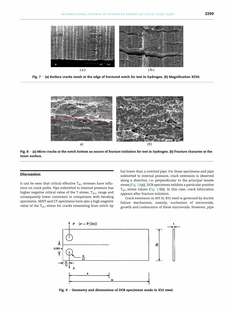
Fig. 7 e (a) Surface cracks mesh at the edge of fractured notch for test in hydrogen. (b) Magnification X250.
Fig. 8 e (a) Micro cracks at the notch bottom as source of fracture initiation for test in hydrogen. (b) Fracture character at the
inner surface.
i n t e r n a t i o n a l j o u r n a l o f h y d r o g e n en e r g y 4 0 ( 2 0 1 5 ) 2 2 9 5e2 3 0 2 2299
Discussion
It can be seen that critical effective Tef,c-stresses have influ-
ence on crack paths. Pipe submitted to internal pressure has
higher negative critical value of the T-stress, Tef,c, range and
consequently lower constraint in comparison with bending
specimens. SENT and CT specimens have also a high negative
value of the Tef,c-stress for cracks emanating from notch tip
Fig. 9 e Geometry and dimensions of D
but lower than a notched pipe. For these specimens and pipe
submitted to internal pressure, crack extension is observed
along x direction, i.e. perpendicular to the principal tensile
stress (Fig. 13(a)). DCB specimens exhibits a particular positive
Tef,c-stress values (Fig. 13(b)). In this case, crack bifurcation
appears after fracture initiation.
Crack extension in API 5L X52 steel is governed by ductile
failure mechanism, namely, nucleation of microvoids,
growth and coalescence of these microvoids. However, pipe
CB specimens made in X52 steel.
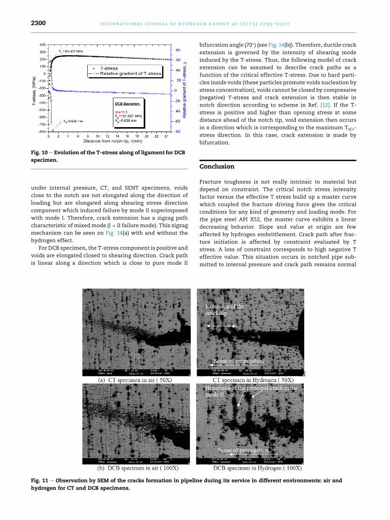
Fig. 10 e Evolution of the T-stress along of ligament for DCB
specimen.
i n t e rn a t i o n a l j o u r n a l o f h y d r o g e n en e r g y 4 0 ( 2 0 1 5 ) 2 2 9 5e2 3 0 22300
under internal pressure, CT, and SENT specimens, voids
close to the notch are not elongated along the direction of
loading but are elongated along shearing stress direction
component which induced failure by mode II superimposed
with mode I. Therefore, crack extension has a zigzag path
characteristic of mixedmode (Iþ II failure mode). This zigzag
mechanism can be seen on Fig. 14(a) with and without the
hydrogen effect.
For DCB specimen, the T-stress component is positive and
voids are elongated closed to shearing direction. Crack path
is linear along a direction which is close to pure mode II
Fig. 11 e Observation by SEM of the cracks formation in pipelin
hydrogen for CT and DCB specimens.
bifurcation angle (70�) (see Fig. 14(b)). Therefore, ductile crack
extension is governed by the intensity of shearing mode
induced by the T-stress. Thus, the following model of crack
extension can be assumed to describe crack paths as a
function of the critical effective T-stress. Due to hard parti-
cles inside voids (these particles promote voids nucleation by
stress concentration), voids cannot be closed by compressive
(negative) T-stress and crack extension is then stable in
notch direction according to scheme in Ref. [12]. If the T-
stress is positive and higher than opening stress at some
distance ahead of the notch tip, void extension then occurs
in x direction which is corresponding to the maximum Tef,c-
stress direction. In this case, crack extension is made by
bifurcation.
Conclusion
Fracture toughness is not really intrinsic to material but
depend on constraint. The critical notch stress intensity
factor versus the effective T stress build up a master curve
which coupled the fracture driving force gives the critical
conditions for any kind of geometry and loading mode. For
the pipe steel API X52, the master curve exhibits a linear
decreasing behavior. Slope and value at origin are few
affected by hydrogen embrittlement. Crack path after frac-
ture initiation is affected by constraint evaluated by T
stress. A loss of constraint corresponds to high negative T
effective value. This situation occurs in notched pipe sub-
mitted to internal pressure and crack path remains normal
e during its service in different environments: air and
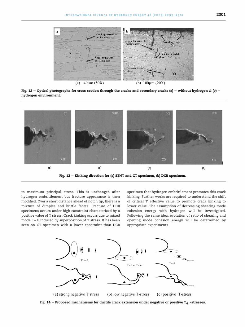
Fig. 13 e Kinking direction for (a) SENT and CT specimen, (b) DCB specimen.
Fig. 12 e Optical photographs for cross section through the cracks and secondary cracks (a) e without hydrogen & (b) e
hydrogen environment.
i n t e r n a t i o n a l j o u r n a l o f h y d r o g e n en e r g y 4 0 ( 2 0 1 5 ) 2 2 9 5e2 3 0 2 2301
to maximum principal stress. This is unchanged after
hydrogen embrittlement but fracture appearance is then
modified. Over a short distance ahead of notch tip, there is a
mixture of dimples and brittle facets. Fracture of DCB
specimens occurs under high constraint characterized by a
positive value of T stress. Crack kinking occurs due to mixed
mode I þ II induced by superposition of T stress. It has been
seen on CT specimen with a lower constraint than DCB
Fig. 14 e Proposed mechanisms for ductile crack ext
specimen that hydrogen embrittlement promotes this crack
kinking. Further works are required to understand the shift
of critical T effective value to promote crack kinking to
lower value. The assumption of decreasing shearing mode
cohesion energy with hydrogen will be investigated.
Following the same idea, evolution of ratio of shearing and
opening mode cohesion energy will be determined by
appropriate experiments.
ension under negative or positive Tef ;c-stresses.
i n t e rn a t i o n a l j o u r n a l o f h y d r o g e n en e r g y 4 0 ( 2 0 1 5 ) 2 2 9 5e2 3 0 22302
r e f e r e n c e s
[1] Chao YJ, Liu S, Broviak BJ. Variation of fracture toughnesswith constraint of PMMA specimens. Proc ASME PVP1999;393:113e20.
[2] Hadj Meliani M, Pluvinage G, Matvienko YG. Two parameterfracture criterion (KreTef) derived from notch fracturemechanics. Int J Fract 2011;167:173e82.
[3] Hadj Meliani M, Azari Z, Pluvinage G, Matvienko YG..Variation of material failure curve with constraint. ProcediaEng 2011;10:710e5.
[4] Yang B, Ravi-Chandar K. Evaluation of elastic T-stress bythe stress difference method. Eng Fract Mech1999;64:589e605.
[5] Chao YJ, Liu S, Broviak BJ. Brittle fracture:variation of fracturetoughness with constraint and crack curving under mode Iconditions. Exp Mech 2001;41(3):232e41.
[6] Hadj Meliani M, Azari Z, Matvienko YG, Pluvinage G. .Theeffect of hydrogen on the material failure curve of APL 5L gaspipe steels. Procedia Eng 2011;10:942e7.
[7] Hadj Meliani M, Azari Z, Pluvinage G, Capelle J. Gougeassessment for pipes and associated transferability problem.Eng Fail Anal 2010;17:1117e26.
[8] Ayatollahi MR, Pavier MJ, Smith DJ. Mode I cracks subjectedto large T-stresses. Int J Fract 2002;117(2):159e74.
[9] Chao YJ, Reuter WG. Fracture of surface cracks underbending loads. In: Underwood JH, MacDonald B, Mitchell M,editors. Fatigue and fracture mechanics, vol. 28.Philadelphia: American Society for Testing and Materials;1997. p. 214e42. ASTMSTP 1321.
[10] Sumpter JDS. An experimental investigation of the Tstresses approach. In: Hackett EM, Schwalbe K-H,Dodds RH, editors. Constraint effects in fracture, ASTM STP1171. Philadelphia: American Society for Testing andMaterials; 1993. p. 492e502.
[11] Hancock JW, Reuter WG, Parks DM. Constraint andtoughness parameterized by T. In: Hackett EM, Schwalbe K-H, Dodds RH, editors. Constraint effects in fracture.Philadelphia: American Society for Testing and Materials;1993. p. 21e40. ASTM STP 1171.
[12] Hadj Meliani M, Azari Z, Pluvinage G, Matvienko YG. Theeffective T-stress estimation and crack paths emanatingfrom U-notches. Eng Fract Mech 2010;77:1682e92.
[13] Hadj Meliani M, Azari Z, Pluvinage G. Constraint parameterfor a longitudinal surface notch in a pipe submitted tointernal pressure. Key engineering materials. Advances instrength of materials, vol. 399; 2009. p. 3e11.
[14] Hadj Meliani M, Benarous M, Moustabchir H, Harriri S,Azari Z. Three-dimensional t-stress to predict the directionalstability of crack propagation in a pipeline with externalsurface crack. SpringerEdition; 2009. Mars 2009.
[15] Ayatollahi MR, Pavier MJ, Smith DJ. Determination of T-stressfrom finite element analysis for mode I and mixed mode I/IIloading. Int J Fract 1998;91:283e98.
[16] Hadj Meliani M, Matvienko YuG, Pluvinage G. Corrosiondefect assessment on pipes using limit analysis and notchfracture mechanics. Eng Fail Anal 2011;18:271e83.
[17] Meshii T, Tanaka T. Experimental T33-stress formulation oftest specimen thickness effect on fracture toughness in thetransition temperature region. Eng Fract Mech2010;77:867e77.
[18] Matvienko YuG. A damage evolution approach in fracturemechanics of pipelines. In: Bolzon G, Boukharouba T,Gabetta G, Elboujdaini M, Mellas M, editors. Integrity ofpipelines transporting hydrocarbons, NATO science forpeace and security series C: environmental security. SpringerNetherlands; 2011. p. 227e44.
[19] Maleski MJ, Kirigulige MS, Tippur HV. A method formeasuring mode I crack tip constraint under dynamic andstatic loading conditions. Soc Exp 2004;44(5).
[20] Cotterell B, Rice JR. Slightly curved or kinked cracks. Int JFract 1980;16:155e69.
[21] Selvarathinam AS, Goree JG. T-stress based fracture modelfor cracks in isotropic materials. Eng Fract Mech1998;60:543e61.
[22] Sumi Y, Nemat-Nasser S, Keer LM. On crack path stability ina finite body. Eng Fract Mech 1985;22:759e71.
[23] Cotterell B. Notes on fracture paths and stability of cracks.Eng Fract Mech 1980;13:526e33.
[24] European project. NaturalHy Project. http://www.naturalhy.net.
[25] Hadj Meliani M, Moustabchir H, Azari Z. T-stress by stressdifference method (SDM): numerical analysis on mode (I)loading. In: Particle and continuum aspect ofmesomechanics. Mesomechanics 2007, Lille, France. ISTEpublishing Knowlge; 2007. p. 253e60.
[26] Sofronis P, Lufrano J. Interaction of local elastoplasticity withhydrogen: embrittlement effects. Mater Sci Eng A1999;260:41e7.
[27] Eliezer D, Eliuaz N, Senkov ON, Froes FH. Positive effects ofhydrogen in metals. Mater Sci Eng A 2000;280:220e4.
[28] Wilkowski G. Leak-before-break: what does it really mean? JPressure Vessel Technol Trans ASME 2000;122(3):267e72.
[29] Liu YH, Cen ZZ, Chen HF, Xu BY. Plastic collapse analysis ofdefective pipelines under multi-loading systems. Int J MechSci 2000;42:1607e22.
[30] Hanneken JW. Hydrogen in metals and other materials: acomprehensive reference to books, bibliographies, workshopsand conferences. Int J Hydrogen Energy 1999;24(10):1005e26.
[31] Capelle J, Gilgert J, Dmytrakh I, Pluvinage G. Sensitivity ofpipelines with steel API X52 to hydrogen embrittlement. Int JHydrogen Energy 2008;33:7630e41.
[32] Capelle J, Gilgert J, Dmytrakh I, Pluvinage G. The effect ofhydrogen concentration on fracture of pipeline steels inpresence of a notch. Eng Fract Mech 2011;78:364e73.
[33] Naturalhy-Project. Burst tests on pipes under pressure ofmixture of hydrogen and natural gaz. Contract no SES6/2004/502661. Durab Integr Work-packages. Subcontract No1401e2005. 2005.