The Magazine for ENERGY EFFICIENCY in … Magazine for ENERGY EFFICIENCY in Compressed Air Systems...
52
The Magazine for ENERGY EFFICIENCY in Compressed Air Systems System Specific Power November 2016 24 BEKO USA CELEBRATES 25 YEARS 12 Kaeser’s Uniform Focus on System Specific Power Benefits UniFirst 18 Centrifugal Air Compressor Basics: Performance Terms and Definitions 38 Aggreko Chillers Assist NASA Tests on Mars SLS Rocket
Transcript of The Magazine for ENERGY EFFICIENCY in … Magazine for ENERGY EFFICIENCY in Compressed Air Systems...

The Magazine for ENERGY EFFICIENCY in Compressed Air Systems
System Specific Power
Nov
embe
r 20
16
24 BEK
O USA CE
LEBRAT
ES 25
YEARS
12 Kaeser’s Uniform Focus on System Specific Power Benefits UniFirst
18 Centrifugal Air Compressor Basics: Performance Terms and Definitions
38 Aggreko Chillers Assist NASA Tests on Mars SLS Rocket

COMPRESSED AIR WITH A VAST PORTFOLIOPowering You With Extraordinary Solutions
Whether the compressed air you need is for machining, fabrication, material handling or finishing, we can help you save money while increasing your productivity. That’s a promise.
www.atlascopco.us – 866-688-9611
Atlas Ad 8.375 x 10.875 - CABP.indd 1Atlas Ad 8.375 x 10.875 - CABP.indd 1Atlas Ad 8.375 x 10.875 - CABP.indd 1Atlas Ad 8.375 x 10.875 - CABP.indd 1Atlas Ad 8.375 x 10.875 - CABP.indd 1Atlas Ad 8.375 x 10.875 - CABP.indd 1Atlas Ad 8.375 x 10.875 - CABP.indd 1Atlas Ad 8.375 x 10.875 - CABP.indd 1Atlas Ad 8.375 x 10.875 - CABP.indd 1Atlas Ad 8.375 x 10.875 - CABP.indd 1Atlas Ad 8.375 x 10.875 - CABP.indd 1Atlas Ad 8.375 x 10.875 - CABP.indd 1Atlas Ad 8.375 x 10.875 - CABP.indd 1Atlas Ad 8.375 x 10.875 - CABP.indd 1Atlas Ad 8.375 x 10.875 - CABP.indd 1Atlas Ad 8.375 x 10.875 - CABP.indd 1Atlas Ad 8.375 x 10.875 - CABP.indd 1Atlas Ad 8.375 x 10.875 - CABP.indd 1Atlas Ad 8.375 x 10.875 - CABP.indd 1Atlas Ad 8.375 x 10.875 - CABP.indd 1Atlas Ad 8.375 x 10.875 - CABP.indd 1Atlas Ad 8.375 x 10.875 - CABP.indd 1Atlas Ad 8.375 x 10.875 - CABP.indd 1Atlas Ad 8.375 x 10.875 - CABP.indd 1Atlas Ad 8.375 x 10.875 - CABP.indd 1Atlas Ad 8.375 x 10.875 - CABP.indd 1Atlas Ad 8.375 x 10.875 - CABP.indd 1Atlas Ad 8.375 x 10.875 - CABP.indd 1Atlas Ad 8.375 x 10.875 - CABP.indd 1Atlas Ad 8.375 x 10.875 - CABP.indd 1Atlas Ad 8.375 x 10.875 - CABP.indd 1 9/1/15 11:20 AM9/1/15 11:20 AM9/1/15 11:20 AM9/1/15 11:20 AM9/1/15 11:20 AM9/1/15 11:20 AM9/1/15 11:20 AM9/1/15 11:20 AM9/1/15 11:20 AM9/1/15 11:20 AM9/1/15 11:20 AM9/1/15 11:20 AM9/1/15 11:20 AM9/1/15 11:20 AM

24
12
34
COLUMNS
4 From the Editor
6 Industry News
41 Resources for Energy Engineers Technology Picks
47 Advertiser Index
48 The Marketplace Jobs and Technology
12 Kaeser’s Uniform Focus on System Specific Power Benefits UniFirst By Roderick Smith, Compressed Air Best Practices® Magazine
18 Centrifugal Air Compressor Basics: Performance Terms and Definitions By Hank van Ormer, Air Power USA
24 BEKO USA Celebrates 25 Years By Compressed Air Best Practices® Magazine
28 CAC Training Leads to Savings at Mitsubishi Hitachi Power Systems Canada By Ron Marshall, Compressed Air Challenge
CHILLER & COOLING BEST PRACTICES SUB-SECTION
34 Maximizing Cooling Tower Technology for HVAC, Power and Industrial Applications By Scott Maurer, SPX Cooling Technologies
38 Aggreko Chillers Assist NASA Tests on Mars SLS Rocket By Steven Bukoski, Aggreko
SUSTAINABLE MANUFACTURING FEATURES
3 airbestpractices.com
COLUMNS N O V E M B E R 2 0 1 6 | V O L U M E 1 1 , N O . 1 0 |

A Key Performance Indicator (KPI) every plant should track, within their energy management metrics, is the “System Specific Power” of their compressed air system. Specific power is how much energy is used (kW) per 100 cfm of compressed air produced. In order to develop this metric, measurements must be taken.
Our lead article is a case study about a UniFirst plant in Kentucky, where Kaeser Compressors performed, what they call, an Air Demand Analysis (ADA). The objective was to improve system specific power and the mechanical reliability of the air compressors. The results were not atypical. The existing system was terrifically oversized and unable to produce compressed air efficiently at such low loads. The specific power of the system was 40.98 kW per 100 cfm. I hope you enjoy the story of how they took it down to 21.56 kW per 100 cfm and improved reliability!
Congratulations go to BEKO USA for celebrating their 25 Year Anniversary. They were kind enough to share photos and notes of what was quite a gathering of their partners and customers at their Atlanta headquarters. Separately, Hank van Ormer supplies us with a useful “Centrifugal Air Compressor Basics” article detailing performance terms and definitions end users and engineers should be familiar with.
Ron Marshall provides us with an interesting story about a Mitsubishi Hitachi Power Systems plant in Saskatoon, Canada. They operate five separate compressed air systems, with a total of 740 horsepower of air compressors installed. Measurement identified a VFD air compressor, with some “internal adjustment issues”, with a specific power as high as 60 kW per 100 cfm!
We have included two interesting articles about chillers and cooling systems. SPX Cooling Technologies is introducing new cooling tower technologies, designed to bring efficiencies to industrial applications. Lastly, who can resist an article about how Aggreko helped, with their mobile chillers, NASA test the Mars SLS Rocket!
Thank you for investing your time and efforts into Compressed Air Best Practices®.
ROD SMITH, Editor, tel: 412-980-9901, [email protected]
FROM THE EDITOR System Specific Power
2016 MEDIA PARTNERS
2016 Expert Webinar SeriesJoin Keynote Speaker Mike Flaherty, from tekWorx, and Chiller & Cooling Best Practices Magazine to review the basics of Energy Treasure Hunts and then how to apply the concept to your facility’s chilled water plant.– by signing up for our free November 30th Webinar titled, “Energy Treasure Hunts for Chilled Water” at www.coolingbestpractices.com/magazine/webinars
COMPRESSED AIR BEST PRACTICES®
EDITORIAL ADVISORY BOARD
Indus
trial
Ener
gy M
anag
ers
Doug Barndt Manager, Demand Side Energy-Sustainability
Ball Corporation
Richard Feustel Senior Energy Advisor Leidos
William Jerald Energy Manager CalPortland
Jennifer Meier Global EH&S/Plant Engineering Manager
Varroc Lighting Systems
Thomas Mort Senior Auditor Thomas Mort Consulting
Brad Reed Corporate Energy Team Leader Toyota
Brad Runda Global Director, Energy Koch Industries
Uli Schildt Energy Engineer Darigold
Thomas Sullivan Energy Performance Manager
Michelin North America
Bryan Whitfield Paint & Powder Booth Specialist
Fiat Chrysler Automotive
Com
pres
sed
Air S
yste
m A
sses
smen
ts
David Andrews Director Marketing Communications Sullair
Erik Arfalk Vice President Communications Atlas Copco
Paul Edwards President Compressed Air Consultants
Tilo Fruth President Beko USA
Chris Gordon President Blackhawk Equipment
Phil Kruger General ManagerHarris Equipment
Frank Langro Director Marketing Festo
Pierre Noack President Aerzen USA
Wayne Perry Sr. Technical Director Kaeser
Kenny Reekie Director, Blower & Vacuum Products
Gardner Denver
Jim Timmersman Senior AuditorPower Supply Industries
Hank Van Ormer Technical Director Air Power USA
Compressed Air & Gas Institute, Compressed Air Challenge
| 1 1 / 1 6
4 airbestpractices.com
COLUMNS


INDUSTRY NEWS
Celanese Recognized as a ENERGY STAR® Partner of the Year-Energy Management
Celanese Corporation is a global technology
leader in the production of differentiated
chemistry solutions and specialty materials
used in most major industries and consumer
applications.
Celanese is receiving
ENERGY STAR®
Partner of the Year
recognition for
formulating a robust energy management
program using ENERGY STAR resources.
Key 2015 accomplishments include:
pp Reducing energy intensity by
7 percent since 2010 and 28
percent since 2005.
pp Completing 200 energy projects
to save more than $16 million
in 2015, including the startup
of a $160 million gas-fired
steam boiler system to prevent
greenhouse gas emissions and
air pollution and to improve
energy efficiency.
pp Investing in energy efficiency in
core production by starting up
a state-of-the-art methanol unit.
pp Performing energy-saving
Treasure Hunts in four facilities
in the United States and Mexico
to identify more than 500 energy-
saving opportunities.
F R E E S U B S C R I P T I O NDIGITAL EDITION FREE WORLDWIDE | PRINT EDITION FREE TO U.S. SUBSCRIBERS
You’ll get FOUR ISSUES of each supplement this year!
p Plastic Injection & Blow Molding
p Chemical Plants & Refineries
p Measurement
p Metal Fabrication & Machining
EVERY ISSUE CONTAINS BEST PRACTICES FOR:
p Industrial Vacuum
p Vacuum Generation
p Industrial & Aeration Blowers
p Blow-Off Air
EVERY ISSUE CONTAINS BEST PRACTICES FOR:
Subscribe at blowervacuumbestpractices.com or coolingbestpractices.com
Subscribe Now! Subscribe Now!
| 1 1 / 1 6
6 airbestpractices.com
COLUMNS

have you Experienced
nano-purification [email protected]
7 0 4 . 8 97. 2 1 8 2
“Your
servic
e is im
peccab
le. Th
ank y
ou!”
- A lo
yal d
istrib
utor
in th
e N
orth
east
C
M
Y
CM
MY
CY
CMY
K
QOTM 13.pdf 1 9/28/2016 9:02:20 AM
pp Sharing its energy management
expertise among the ENERGY
STAR industrial partners.
pp Communicating energy efficiency
and ENERGY STAR throughout
Celanese.
For more information, visit www.celanese.com/ehs/sustainability or www.energystar.gov
Baldor Introduces Passport Selection Tool for Baldor-Dodge® Products
Baldor Electric Company introduces Passport,
a new selection program for Baldor-Dodge®
mechanical power transmission products.
Passport is a web-based tool utilizing an
intuitive process to guide both novice and
expert users through quick and accurate
selections.
During the selection process, Passport offers
real-time pricing and availability, enabling
customers to make cost effective selections of
readily available components. After selections
are complete, Passport offers add-to-order
capability, seamlessly allowing customers
to convert selections into orders via the PT
Place e-commerce platform. Passport also
delivers a comprehensive summary that
includes part numbers, supporting technical
performance data and indexes product
selections for future reference.
Currently, Passport supports the selection of
shaft mounted reducers, as well as V-Belt and
synchronous belted drives. Future Passport
“During the selection process, Passport offers real-time pricing and availability,
enabling customers to make cost effective selections of readily available components.”
1 1 / 1 6 |
7 airbestpractices.com
COLUMNS

INDUSTRY NEWS
capabilities will incorporate additional
Baldor-Dodge mechanical power transmission
products, as well as offering an application
based approach to developing packaged
solutions for a wide range of common
industrial applications such as conveying
and air handling.
About Baldor Electric Company
Baldor Electric Company (www.baldor.com)
is a leading marketer, designer and
manufacturer of industrial electric motors,
drives, and mechanical power transmission
products. Baldor, a member of the ABB Group,
is headquartered in Fort Smith, Arkansas.
For more information, visit www.baldor.com access Passport at www.passport.baldor.com or watch the YouTube video to learn more.
Festo Helps Create Mechantronic Apprenticeship Program
Two-year apprenticeship program helps
employers fill the skills gap in advanced
manufacturing.
Festo Didactic, Sinclair Community College and
five companies in the Cincinnati tri-state area
(Art Metal Group, Clippard Instruments, Festo
Inc., MQ Automation, Nestlé) recently created
a two-year Mechatronics Apprenticeship
Program to help employers develop the skills
Passport is a web-based tool utilizing an intuitive process that offers real-time pricing and availability.
| 1 1 / 1 6
8 airbestpractices.com
COLUMNS

+
All BEKO Technologies dryers are designed and tested to meet the strict quality guidelines of our company.There are no compromises to quality and reliability of any of our dryers.
Our promise
FEATURES AND BENEFITS
The operation of compressed air systems with conventional heatless and heated desiccant dryers can suffer from high, system-related air loss. This deficiency needs to be compensated via an increase in compressor performance, thus requiring a higher energy input.
EFFICIENT LOWDEW POINT
HEATLESSDESSICANT
DRYING
The DRYPOINT® Principle
Truth in Compressed Air
INNOVATIVE, RELIABLE DESIGN: • high quality components are used in
construction and combined with high
level engineering
• simplifies maintenance and reduces PM costs
WIDE STANDARD RANGE: • DRYPOINT® XC: up to 2,800 scfm from 60 to 7,250 psig
• DRYPOINT® XF: up to 6,000 scfm
BOTH FULLY CUSTOMIZED ENGINEERING
SOLUTIONS AVAILABLE
INTELLIGENT OPERATION: • each dryer includes a feature rich
controller with energy saving modes
DRYPOINT® XFi : depoint demand
standard (XFi) and autonomous
selection method of regeneration and
cooling for optimized energy savings
DRYPOINT® XC and DRYPOINT® XF desiccant dryers offer a convincing,economic solution to the problem: Energy savings of up to 80% can be realized when compared to conventional designs.
EFFICIENT LOWDEW POINT
HEATLESSDESSICANT
DRYING
• DRYPOINT® XC: up to 2,800 scfm from 60 to 7,250 psig
BOTH FULLY CUSTOMIZED ENGINEERING
selection method of regeneration and
cooling for optimized energy savings
XF desiccant dryers offer a convincing,
HYPER-INTELLIGENT
HEATED DESICCANT
DRYING
that are missing in the workforce today by
combining theoretical education, hands-
on training, and on the job training. The
apprenticeship is designed to help individuals
learn advanced manufacturing skills as well
as earn an associate’s degree in mechatronics.
Building off a German model
The first cohort of the program includes 11
apprentices who are training for careers
as maintenance technicians, automation
specialists, service technicians, and
manufacturing technicians. The program
uses the German apprenticeship model of
dual education, where apprentices learn in a
classroom and maintain a steady job. Every
week each apprentice spends one day at
Sinclair Community College for classes, one
day using state-of-the-art equipment at the new
Festo Learning Center in Mason, and three days
working at their respective employers. The
apprentices are able to take what they learn
in class, practice it at the Festo Learning Center,
and then use that new knowledge and skill
in a real-life work environment. “In terms of
educational modality, the apprenticeship model
couldn’t be a better fit for manufacturing,” says
Vice President for Regional Centers at Sinclair
Community College Scott Markland.
The Festo Learning Center is a unique part of
the program. The Center is designed to meet
international standards for production facilities
and labs. It provides the apprentices a training
facility where they can work with instructors
on high-end Festo workstations that simulate
a work environment and corresponds to their
classroom curriculum.
Collaboration to address the skills gap
The idea for the apprenticeship program was
born out of a need for highly skilled workers
in the Cincinnati area, an established hub for
manufacturing. As advanced manufacturing and
Industry 4.0 grow in the area, employers are
increasingly looking for mechanical aptitude,
skills in automation, the ability to read code
and program machines, and electrical skills as
1 1 / 1 6 |
9 airbestpractices.com
COLUMNS

well as problem solving and critical thinking
skills. “Technology is evolving quickly,” says
Jennifer Paine, Site Management Lead at Nestlé.
“For us this is about a commitment to our
employees, to train them in the skills they need
and to advance their skill set to make our
company more competitive.”
Based on the need from employers and a
shared vision to ensure more people receive
the training and education needed for today’s
manufacturing jobs, the partners formed the
Mechatronics Apprenticeship Program Partners
collaborative. The partners worked together
to identify the needs of employers and adapt
an existing curriculum at Sinclair Community
College accordingly, in order to solve both the
educational needs and the workforce needs of
the community. “We were hearing from local
employers about these needs, but we felt like
individually we may not have all the pieces
to do it alone but it was something we could
collaborate on based on our common vision,”
says Scott Markland.
Apprentices with bright futures
The program gives the apprentices an
advantage in the workforce. Unlike students
who are only earning an associate’s degree,
the mechatronics apprentices are gaining
the knowledge and skills they need as well
as getting practical experience. “We must
continue to find ways to train students in
the skills and knowledge they need for
today and tomorrow’s manufacturing jobs.
INDUSTRY NEWS
Sepremium Oil/Water Separator
Compressed Air Saving Products
COMPRESSED AIR ALSO PRODUCES
OILY CONDENSATE*
Help ensure it doesn’t impact our
ENVIRONMENT.
Zero Air-Loss Condensate Drains
ELECTRONIC
NO ELECTRICITY REQUIRED
Smart Guard Ultra
Mini Mag Filter Applications
Mini Mag SP Filter Applications
POD-TD Receiver Applications
Smart Guard Smart Guard Mini Air-Saver G2Air Leak Lock-Down
Locator-EVUltrasonic Air Leak Detection
JORC Industrial LLC. • 1146 River Road • New Castle, DE 19720 Phone: 302-395-0310 • Fax: 302-395-0312 • [email protected] • www.jorc.com
* A 250 hp compressor can produce 40,515 gallons of oily condensate per year.
JORC Zero Air-Loss Condensate Drains and Oil/Water Separators provide
SUSTAINABLE CONDENSATE
MANAGEMENT
| 1 1 / 1 6
10 airbestpractices.com
COLUMNS

INDUSTRY NEWS
Discover More www.sullivan-palatek.com \ 219.874.2497
The SP16-75 Rotary Screw Air CompressorIn industries that require constant and dependable air power, the SP16-75 75hp is expertly engineered to be both reliable and energy
of environments. The unit is one of many products in a large line of versatile industrial electric air
Palatek that boasts our robust factory made Air End. For more information, call or visit our website for details.
WHERE VERSATILITYMEETS PRECISION
Apprenticeship programs like this, help make
sure students get that training early,” says
Thomas Lichtenberger, President at Festo
Didactic North America.
For one apprentice it’s about recognizing
what is happening in the rest of the world and
getting a jump-start on his competition. “This
is the future of maintenance tech. The more I
talk to people in this field the more I see how
it is big over in Europe and it’s coming this
way. You get in on the ground floor and you’ll
be set,” says Nathan Gledhill, a mechatronics
apprentice and Nestlé employee.
About Festo Didactic
Festo Didactic is a leading provider of
technical education equipment and training.
Festo’s educational solutions evolved from
its world-class automation and engineering
division and integrates the latest trends in
each learning system it offers. The innovative
product range from Festo allows educators
and trainers to equip their classroom with
the technology they need, from individual
workstations to complete Learning Factories,
as well as training and consulting, eLearning,
courseware solutions, and LMS integration.
To become a Mechatronics Apprenticeship
Program partner or for more information
contact Corinne Haley by email at corinne.
[email protected] or by telephone at 848-
777-2009.
For more information, visit http://www.festo-didactic.com/int-en/
1 1 / 1 6 |
11 airbestpractices.com
COLUMNS

KAESER’S UNIFORM FOCUSon System Specific Power Benefits UniFirstBy Roderick Smith, Compressed Air Best Practices® Magazine
cpUniFirst is one of North America’s largest
workwear and textile service companies.
They outfit nearly two million workers in
clean uniforms and protective clothing each
workday. Founded in an eight-stall garage
in 1936, the Company has grown to 240
UniFirst’s Tim Davis and Bill Jackson approved the performance of an Air Demand Analysis to better
understand system flow requirements (left to right).
| 1 1 / 1 6
12 airbestpractices.com
SUSTAINABLE MANUFACTURING FEATURES
customer servicing locations throughout the
U.S. and Canada servicing 300,000 business
customer locations. UniFirst operates five
company-owned manufacturing plants and
two state-of-the-art distribution centers. The
subject of this article is an energy-saving Air
Demand Analysis (ADA), conducted by Kaeser
Compressors, at UniFirst’s centralized 320,000
square foot hub Distribution Center located in
Owensboro, Kentucky.
Discovering the “Specific Power” of the System
The compressed air system that Dennis
Ginn, from the Louisville branch of Kaeser
Compressors, found installed in Owensboro
consisted of two fifty horsepower rotary
screw air compressors, a wet receiver tank
and a refrigerated air dryer. UniFirst invited
him in because they were experiencing
mechanical issues with the air compressors.
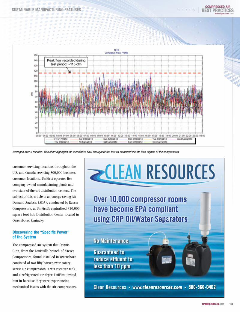
Averaged over 5 minutes. This chart highlights the cumulative flow throughout the test as measured via the load signals of the compressors.
Over 10,000 compressor rooms have become EPA compliant using CRP Oil/Water Separators
Clean Resources • www.cleanresources.com • 800-566-0402
No Maintenance
Guaranteed to reduce effluent to less than 10 ppm
using CRP Oil/Water Separators
www.cleanresources.com
Over 10,000 compressor rooms have become EPA compliant using CRP Oil/Water Separators
• 800-566-0402 www.cleanresources.com
using CRP Oil/Water Separators
www.cleanresources.com
1 1 / 1 6 |
13 airbestpractices.com
SUSTAINABLE MANUFACTURING FEATURES

KAESER’S UNIFORM FOCUS ON SYSTEM SPECIFIC POWER BENEFITS UNIFIRST
“They were thinking of buying two new 50
hp air compressors. The first thing I noticed,
however, was the air compressors were
short-cycling,” Ginn said. “A unit would load,
unload, load, unload and just kept repeating
the cycle.” Ginn learned this constant start/
stop condition was the norm and informed
the plant this was the most likely cause of the
mechanical issues.
The second 50 horsepower air compressor
was strictly used as backup. UniFirst
production runs 24/7 and cannot tolerate
any downtime from the compressed air
system. Compressed air is “mission critical”
as it is used throughout the plant to power
pneumatic cylinders used in the vast
conveying system moving laundry around
the plant. The conveyors have gates, opened
and closed by pneumatic cylinders actuated
by solenoid valves. Vast numbers of 2" x
3" sewing labels are also sorted, packaged
and manipulated with compressed air. No
compressed air would mean no production.
Members of the maintenance team confirmed
they manually rotated the units once a week
so as to even out the running hours. Ginn
continued, “Once we learned the second
air compressor never ran with the first one,
we knew the system was over-sized and that
UniFirst would benefit from a Kaeser Air
Demand Analysis.”
Kaeser’s Air Demand Analysis (ADA) builds
a demand profile by measuring system
parameters including flow, pressure, and
energy usage (kWh) during a representative
work week. One important goal is to
discover the important performance metric
called “Specific Power” for the whole
compressed air system. Specific power is
how much energy is used (kW) per 100
cfm of compressed air produced. Tim Davis
(Facilities Engineer) and Bill Jackson, DC
(Distribution Center) Maintenance Planner,
approved the suggestion to go forward with
an ADA and received management support to
get it done.
TABLE 1. SYSTEM PROPOSAL AFTER ADA AIR DEMAND ANALYSIS
PERFORMANCE METRICSADA DATA ON
EXISTING SYSTEM
PROPOSED SYSTEM WITH TWO SK 15T AIR COMPRESSORS + A BACK-UP UNIT + STORAGE
Annual Energy Cost $16,732 $8,088
Annual Energy Consumption 223,093 kWh 115,359
Max Power Consumption 35.2 25.8
Specific Power (kW/100 cfm) 40.98 21.22
BUILT FOR TODAYC O M M I T T E D T O T O M O R R O W
AW
ARD WINN
ING
More than 160 years ago, the FS-Curtis way of doing business was established through two key commitments: a dedication to building quality products and a
dedication to responsive customer service. Over the decades, the company and its products have evolved through innovation and new technologies. But those commitments to quality and service remain unchanged. Today, just as in 1854, FS-Curtis customers can depend on our products for reliable, long-term service. Equally as important, they can depend on
getting the same from our people.
| 1 1 / 1 6
14 airbestpractices.com
SUSTAINABLE MANUFACTURING FEATURES

After one week of measurement, the ADA report was produced.
Specific power was measured at 40.98 kW per 100 cfm
of compressed air produced- close to double what Kaeser
Compressors targets when designing compressed air systems.
The annual energy consumption was 223,093 kWh, costing the
plant $16,732. Average system pressure (measured at the receiver
tank) was 111 psi. Ginn commented, “The ADA showed their air
compressors were oversized. The air compressors can produce
at least 200 cfm each and the system was only consuming 70 cfm,
on average, with peak consumption reaching only 115 cfm.” The
air compressors, only able to operate in on/off mode, were simply
unable to operate efficiently and reliably at such low loads.
TABLE 2. SYSTEM DATA COMPARISON AFTER INSTALLATION
PERFORMANCE METRICSADA DATA ON
EXISTING SYSTEMSAM 4.0 DATA ON
NEW SYSTEM
Annual Energy Cost $16,732 $9,035
Annual Energy Consumption 223,093 kWh 120,461
Max Power Consumption 35 25
Average kW Draw 26 14
Specific Power (kW/100 cfm) 40.98 21.56
Total Flow (cf/yr) 32,666,894 33,525,531
Available Capacity (cfm) 388 213
Peak Flows (cfm) 115 142
Average Flow (cfm) 62 64
Maximum Tank Pressure (psig) 124 125
Average Tank Pressure (psig) 111 118
*Energy costs for both systems calculated at the current energy rate of $0.075/kWh
1 1 / 1 6 |
15 airbestpractices.com
SUSTAINABLE MANUFACTURING FEATURES

Designing the Industry 4.0 System Solution
Armed with the average flow requirement
data, Ginn was able to design a system
able to increase (almost double) specific
power efficiency while maintaining the
back-up assurances the maintenance
team required. The new system would
consist of three SK 15 AIRCENTER
rotary screw air compressors equipped
with integrated refrigerated dryers
and receivers, the existing 400-gallon
receiver tank, aluminum SmartPipe™
piping, and an oil aerosol coalescing
filter. “We proposed three air
compressors each sized for average
demand and the second one to act as
the trim compressor. The third unit
would provide the redundancy UniFirst
requires.” Ginn continued, “I always
tell my clients that storage is our friend,
so we kept the receiver tank and placed
the pressure transducer and set it at
115 psi.”
The three SK 15 AIRCENTER air
compressors would be controlled by
a Sigma Air Manager (SAM) 4.0. This
master controller is connected to the
three air compressors through the
Ethernet. When the system pressure
reaches 115 psi, it will activate the
second air compressor. It will also rotate
the air compressors to keep the working
hours even during the year. This allows
for one preventative maintenance service
trip to be done for all the units. Another
feature of the SAM 4.0—it provides the
plant with up to one year of reporting,
including energy consumption and costs.
The new system features three air compressors (one for back-up) with space-saving integrated dryers.
KAESER’S UNIFORM FOCUS ON SYSTEM SPECIFIC POWER BENEFITS UNIFIRST
| 1 1 / 1 6
16 airbestpractices.com
SUSTAINABLE MANUFACTURING FEATURES

Most importantly, specific power was
forecasted to drop in half from 40.98 to
21.22 kW/100 cfm. Maintenance issues,
caused by short-cycling, would go away as the
units would no longer be undersized. After
deliberation, UniFirst management decided
to install the new system.
Compressed Air Systems are Dynamic
Several months after the new compressed
air system had been up and running, a
representative day was selected to examine
the performance metrics of the system. The
UniFirst team was taught how to run the
reports themselves off the card in the Sigma
Air Manager 4.0. The results were exciting
in that not only was specific power cut
in half – the proposed/anticipated results
were met almost exactly. “Specific power
was cut from 40.98 to 21.56 kW/100 cfm,”
said Ginn. “When clients can take the time
to have an ADA Survey done, it’s not difficult
to accurately predict the performance of a
new system.”
Mechanical issues caused by short-cycling,
over-sized air compressors were no longer
an issue and the system was moved to an
elevated mezzanine. Ginn commented, “This
is an air conditioned facility ideal for our
AIRCENTERS featuring space-saving integrated
refrigerated dryers. They make a nice tall and
skinny package.”
As is normal with compressed air systems,
the Sigma Air Manager 4.0 Report showed
operating conditions had changed.
Compressed air flow and pressure
requirements had actually increased. The
Sigma Air Manager 4.0 had automatically
adjusted and the good system design had
nevertheless delivered the lower energy
consumption figures.
Conclusion
Compressed air is “mission critical” in
many facilities. Since production personnel
know the plant will shut-down if there’s no
compressed air, this makes the over-sizing
of air compressors common-place. Over-sized
air compressors, with load/unload controls,
will short-cycle and experience mechanical
issues and elevated energy costs. “We run
into this situation (where the plant doesn’t
understand system demand) all the time,”
said Ginn. “Plants will always err on the side
of caution. I just sold a 40 horsepower VSD
air compressor to a plant which originally
wanted to buy a 150 horsepower air
compressor.”
Installations like this one, designed after
a system analysis is done, show redundancy
assurance need not be sacrificed while
attaining energy efficiency improvements
in compressed air system specific power.
For more information contact Kaeser Compressors at email: [email protected] or visit us.kaeser.com/cabp
To read similar Compressed Air System Assessment articles, visit www.
airbestpractices.com/system-assessments
1 1 / 1 6 |
17 airbestpractices.com
SUSTAINABLE MANUFACTURING FEATURES

CENTRIFUGAL AIR COMPRESSOR BASICS: Performance Terms and DefinitionsBy Hank van Ormer, Air Power USA, Inc.
cpIn general, this article focuses on the
definitions of terms often used to understand
centrifugal air compressor performance.
Comments are also made on how to measure
power consumption. This article is not
intended to be an engineering discussion of
the various types and designs of centrifugal
and other air compressors.
Compressor Capacity Definitions
Following are some clarifying definitions of
terms used, and often misused, to define
capacity or flow in centrifugal compressors.
Capacity is the quantity of air at which the
compressor will operate at a specific discharge
pressure. For all industrial compressors,
capacity is rated at the conditions of pressure,
temperature and moisture content existing
at the compressor inlet flange. The basic
reference for all discussion on air flow
relates back to mass flow. All definitions and
conversions are directly related to conservation
of mass flow through the compressor.
Mass flow (lb/min or kg/hr) is a specific
value independent of the air inlet conditions.
The compressor functions on how much mass
flow (lb/min) flows through the machine. For
this reason it is the best means of comparing
one flow value to another. The problem
with using it all the time is that compressor
manufacturers size compressors on actual
inlet air volume flow. This is done because the
compressor size is a function of the actual inlet
volume it can hold.
pp lb/min wet is the mass of air including the water vapor in the air.
pp lb/min dry is the mass of the air without the water content i.e. dry air
(0% relative humidity)
“Capacity requirements, in terms of scfm, are best to use because scfm is directly proportional to mass flow; which,
when estimated can accurately reflect the input power value.”— Hank van Ormer, Air Power USA, Inc.
| 1 1 / 1 6
18 airbestpractices.com
SUSTAINABLE MANUFACTURING FEATURES

CFM (cubic feet per minute) (M3/min) is
a volumetric measurement not dependent on
inlet conditions such as temperature, pressure
and humidity. When working with centrifugal
compressors, this should be clarified (when
working with all compressor types, this should
also be clarified).
ACFM (actual cubic feet per minute) (M3/
min) is the actual inlet air delivered at the
discharge flange. ACFM represents useful air
and is independent of the seal losses through
the machine. The commonly used value for
seal losses with carbon seals is about 1%.
ICFM (inlet cubic feet per minute) (or
M3/hr) is a measure of the air entering the
compressor referred back to inlet conditions.
ICFM is the most common method of
determining centrifugal compressor selection.
CAGI and PNEUROP often rate centrifugal
compressors in icfm. The only difference
between icfm and acfm is that acfm is
measured at the compressor discharge flange,
whereas icfm is measured at the compressor
inlet flange or at the discharge flange and
corrected for seal losses. Some centrifugal
compressors may have other air losses
between the inlet and discharge flanges.
Unlike positive displacement type compressors
where icfm is almost always significantly higher
than acfm and with the exception of such small
items as potential seal leakage, icfm and acfm
are often used interchangeably with regard to
capacity flow ratings.
FAD (free air delivered) indicates delivered
air at inlet conditions. FAD is read before the
inlet filter and inlet piping thus not taking into
account this pressure drop which is normally
anywhere from .2 to .5 psia with a relatively
clean filter. This can be misleading because
performance is calculated on an inlet pressure
that is higher than the actual air volume
entering the unit. Calculated discharge pressure
and power will also be lower than actual.
IS EVERYTHINGGerald “Gerry” Bauer President, EccoFab - Rockford, IL
Sullair.com/GerrysStory
It doesn’t quit. It doesn’t even think about quitting. In fact, it doesn’t think of anything but the job at hand.
Sound familiar?Our compressors are a lot like the people who use them.
Discover the complete line of Sullair stationary air compressors, featuring the legendary Sullair air end.
To learn more about our complete line, including air treatment products, contact your local distributor or visit our website.
IS EVERYTHINGReliability
1 1 / 1 6 |
19 airbestpractices.com
SUSTAINABLE MANUFACTURING FEATURES

This heatless regenerative desiccant dryer from SKF typically uses less than 8% purge air, yet delivers superior dew points now with Bluetooth LE technology.
• Synchronous compressor control matches dryer to compressor run times
• Smart cycle selection to lower energy consumption & dew points
Simple to service
• Time-to-Service email notifications
• Track all service activities Track all service activities Twithin the Smart Valve AppSmart Valve App
• Simply spin off the high temperature desiccant cartridgestemperature desiccant cartridges
SKF’s SFD just got SmarterIntroducing the SKF separator filter dryer (SFD) with Smart Valve
NEW!!
Please contact SKF for questions and ordering, 1-888-753-3477
® SKF is a registered trademark of the SKF Group. | © SKF Group 2016
CENTRIFUGAL AIR COMPRESSOR BASICS: PERFORMANCE TERMS AND DEFINITIONS
Like icfm and acfm, FAD is also used
interchangeably to reference delivered air.
However, if using published data to run
operating performance compressors it is
important to know if the FAD rating is used
instead of icfm or acfm and identify where
the inlet pressure number is being acquired
or estimated.
SCFM (standard cubic feet per minute)
(Nm3/hr) is referred to normal inlet conditions
of 14.5 psia (1 bar), 68˚F (20˚C), and 0%
relative humidity. SCFM can be based on
inlet or discharge and it should be specified
one way or the other. The most common use
is inlet flange measurement.
Capacity requirements, in terms of scfm,
are best to use because scfm is directly
proportional to mass flow; which, when
estimated can accurately reflect the input
power value. ICFM will yield varying amounts
of mass flow depending on the extent to
which moisture is removed during intercooling
and aftercooling. Most air tools, dryers,
flow meters and similar air equipment are
rated on the basis of scfm, not icfm or acfm.
Air Power USA always uses scfm when selecting
or applying compressors to a project or when
comparing operating performance of various
units. Be careful to avoid overthinking that
scfm ratings always permit direct comparisons
as there are several definitions for “standard”
conditions. Both CAGI and PNEUROP use 68˚F,
14.5 psia, and 0% relative humidity ambient
air conditions as standard.
In summary, operating comparisons
should only be evaluated at the same inlet
temperature, pressure, relative humidity and
cooling water conditions, as well as the same
discharge pressure. The user’s application
should specify worst case conditions, i.e.
warmest conditions to insure the compressor
is capable of meeting the desired output.
Converting acfm to scfm – establishing a general multiplier
* (.494) The saturation pressure of the water vapor at the inlet temperature (95°F) times the actual RH% is deducted from the available inlet air to allow for the water vapor removal in the form of condensate.
| 1 1 / 1 6
20 airbestpractices.com
SUSTAINABLE MANUFACTURING FEATURES

New CPC-G 40-60 hpGear Drive Rotary Screw Compressor
1-877-861-2722 [email protected] www.cpcompressors.com• •
Experience the Efficiency of Red!
• New compact design – 25% smaller footprint• Improved flow and efficiency• Integrated dryer variant available • Low sound enclosure• Radial Fan• Reduced oil capacity (-18%)• Water Separator• ES4000 Advanced Controller• ICONS ready (remote visualization)• 100–125–150–175 psig available• Backed by our 5 year warranty
(restrictions apply)
NEWDESIGN
Now available with integrated dryer!
When not specified most manufacturers
default to standard design conditions of:
Inlet = 95˚F
Barometric = 14.4 PSIA
Inlet 14.1 PSIA
Relative humidity = 60%
Cooling water = 80˚F
Compressor Pressure Definitions
PSI is a pressure rating which means pounds
per square inch.
PSIG is gauge pressure which reads the psi
above the ambient or barometric pressure:
0 psig = 14.5 psia (nominal sea level)
100 psig = 114.5 psig
PSIA is ambient barometric pressure that
varies with the altitude and the weather. This
is a very important value when evaluating
or estimating any compressor performance;
particularly, centrifugal compressors. PSIA is
also critical to convert icfm or acfm to scfm
Understanding horsepower and power cost
1 1 / 1 6 |
21 airbestpractices.com
SUSTAINABLE MANUFACTURING FEATURES

CENTRIFUGAL AIR COMPRESSOR BASICS: PERFORMANCE TERMS AND DEFINITIONS
(M3/hr to Nm3/hr). The Standard Value for
inlet air used by CAGI and PNEUROP, and most
manufacturers, is 14.5 psia (1 bar).
Input Power
A common area of misunderstanding where
comparing projected or actual operating
compressors, but particularly centrifugals.
Motor horsepower – no meaning to power
cost, may or may not have service factor
usually references the nameplate horsepower.
BHP – brake horsepower is the input power
at the compressor input shaft; power required
to drive compressor at rated flow and rated
pressure.
Input motor power in kW – value which
can be measured or calculated that generates
kWh; the driving force of the utility bill. Input
motor power is affected by such factors as
motor efficiency (ME), power factor (PF),
motor conditions, starter and disconnect
conditions, power quality, and when not at
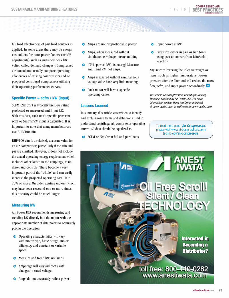
Typical electric motor operating characteristics (.90 ME) -- Measure and trend kW, not amps
| 1 1 / 1 6
22 airbestpractices.com
SUSTAINABLE MANUFACTURING FEATURES
InterestedinBecomingaDistributor?
full load effectiveness of part load controls as
applied. In some areas there may be energy
cost adders for poor power factors (or kVA
adjustments) such as sustained peak kW
(often called demand changes). Compressed
air consultants usually compare operating
efficiencies of existing compressors and or
proposed centrifugal compressors utilizing
their operating performance curves.
Specific Power = scfm / kW (input)
SCFM (Nm3/hr) is typically the flow rating
projected or measured and input kW.
With this data, each unit’s specific power in
scfm or Nm3/hr/kW input is calculated. It is
important to note that many manufacturers
use BHP/100 cfm.
BHP/100 cfm is a relatively accurate value for
an air compressor, particularly if the cfm and
psi are clarified. However, it does not include
the actual operating energy requirement which
includes other losses in the couplings, main
drive, and controls. These become a very
important part of the “whole” and can easily
increase the projected operating cost 10 to
20% or more. On older existing motors, which
may have been rewound one or more times,
this disparity could be much larger.
Measuring kW
Air Power USA recommends measuring and
trending kW directly into the motor with the
appropriate number of data points to accurately
profile the operation.
pp Operating characteristics will vary with motor type, basic design, motor efficiency, and constant or variable speed.
pp Measure and trend kW, not amps.
pp Amperage will vary indirectly with changes in rated voltage.
pp Amps do not accurately reflect power
pp Amps are not proportional to power
pp Amps, when measured without simultaneous voltage, means nothing
pp kW is power! kWh is energy! Measure and trend kW, not amps:
pp Amps measured without simultaneous voltage value have very little meaning.
pp Each motor will have a specific operating curve.
Lessons Learned
In summary, this article was written to identify
and explain some terms and definitions used to
understand centrifugal air compressor operating
curves. All data should be equalized to:
pp SCFM or Nm3/hr at full and part loads
pp Input power at kW
pp Pressures either in psig or bar (only using psia to convert from icfm/acfm to scfm)
Any activity lowering the inlet air weight or
mass, such as higher temperature, lowers
pressure after the filter and will reduce the mass
flow, scfm, and input power accordingly.
This article was adapted from Centrifugal Training Materials provided by Air Power USA. For more information, contact Hank van Ormer at [email protected], or visit www.airpowerusainc.com.
To read more about Air Compressors, please visit www.airbestpractices.com/
technology/air-compressors.
1 1 / 1 6 |
23 airbestpractices.com
SUSTAINABLE MANUFACTURING FEATURES

BEKO USA Celebrates 25 YearsBy Compressed Air Best Practices® Magazine
cpEarlier this year, BEKO Technologies completed the third
renovation of its eight-year-old facility, which provided perfect timing
for the company’s 25th Anniversary Event held on September 22,
2016 in Atlanta, GA. The celebration marked 25-years of operating
in the American markets after the German parent company, BEKO
Technologies GmbH, first set up shop in the Tulsa, OK area in mid-
December of 1990. This important milestone was celebrated with
a guided tour at the newly renovated American headquarters that
included new product introductions and live demonstrations, live
music and art, and a catered luncheon, along with a presentation from
executives from both the United States and Germany. All of which was
followed by a private party that evening.
“We are thrilled to celebrate a quarter of a century providing ancillary equipment to the compressed air industry.”
— Tilo Fruth, President of BEKO Technologies, Corp.
| 1 1 / 1 6
24 airbestpractices.com
SUSTAINABLE MANUFACTURING FEATURES

BEKO Technologies has been manufacturing and selling industrial
technology products throughout the United States, Canada, Mexico
and South America since 1991. The American headquarters is located
in Atlanta, GA and aside from the German parent company, it is by far
the largest subsidiary and manufacturing location within the group,
as well as the fastest growing one. During the afternoon portion of the
celebration, the company unveiled the first of its kind hyper-intelligent,
heated, blower operated desiccant dryer to a full house audience.
New Technologies on Display
In addition, the guided tour offered visitors a first-hand chance to
see how BEKO USA manufactures its unique membrane technology,
optimized their facility to better serve customers, as well as another
exclusive product introduction with the very first membrane air dryer
with user programmable dew point controls. The company strives for
dynamic and healthy growth and wants to be the technology and quality
leader within the market. “We are thrilled to celebrate a quarter of a
century providing ancillary equipment to the compressed air industry,”
said Tilo Fruth, President of BEKO Technologies, Corp.
This event was the world debut of the Drypoint® M eco control
membrane dryer technology. The units are equipped with temperature
and humidity sensors, a control board, and purge control valves.
These allow users to set programmable stable or dynamic pressure
dew points. This type of dynamic purge control creates significant
energy efficiency opportunities in the form of lower purge air use. As
ambient and inlet (to the dryer) temperatures increase during the day,
for example, the dynamic mode can allow pressure dew point to rise
as the dew point suppression remains consistent and the compressed
air remains dry.
BEKO Technologies USA President, Tilo Fruth, receiving a 25 Years Certificate from BEKO Technologies GmbH CEO Manfred Lehner (left to right).
The newly introduced DRYPOINT XF heated blower purge dryer with ecointelligence auto-adjusting software for purge-saving control.
1 1 / 1 6 |
25 airbestpractices.com
SUSTAINABLE MANUFACTURING FEATURES

BEKO USA CELEBRATES 25 YEARS
If an end user wants a stable pressure dew
point, they can choose six different settings
ranging from +10 C to -26 C. This allows end
users to experiment with higher dew point
specifications (in order to achieve lower
purge rates) when before they may have been
locked in to one low dew point specification.
Compressed air systems are perhaps best
defined as dynamic. Ambient and inlet
temperatures, operating pressures and
compressed air consumption rates are always
changing. Many applications simply require
dew point suppression (from ambient and
inlet) to achieve dry air. In order to program
the dynamic dew point, users choose six
settings (from 10 to 55 Kelvin) establishing
a stable difference between compressed air
inlet temperature and dryer outlet pressure
dew point.
Other newly launched technologies included
the DRYPOINT XC heatless desiccant dryer
with BEKOTOUCH controls, the DRYPOINT XF,
a heated blower purge dryer (patent pending)
with environmentally aware auto-adjusting,
ecointelligence software and BEKOTOUCH 2
interface, and DRYPOINT CT and VSD cycling
and variable speed refrigerant dryers.
Customer and Employee Celebration
The afternoon event concluded with a live
performance of a remix of the official BEKO
Technologies’ song by local band, The
Bucket Crew, and was followed-up with
by a commissioned piece of artwork being
created live in front of visitors by local artist
Dusty Mauldin during the lunch, meet and
greet before heading back to the midtown
Almost 200 guests toured the newly renovated facility with 30% more warehouse capacity, energy saving LED lighting, 40% solar power, and 30% energy consumption reduction.
The facility tour included six showcases of recently launched, innovative products like the Drypoint® M ecocontrol membrane dryers
| 1 1 / 1 6
26 airbestpractices.com
SUSTAINABLE MANUFACTURING FEATURES

area to relax before the evening event. The
evening event was held a Summerour Studio
overlooking the downtown skyline of Atlanta
where guests were treated to a hanging
champagne display served by stilt-walkers
during the cocktail hour that was followed by
a lovely sit down dinner. There was a moment
just between the end of the cocktail hour and
dinner service that was the perfect opportunity
for one of the most important parts of
the entire day – honoring the company’s
customers and employees.
Time was specifically set aside in order to
present special plaques recognizing several
customers’ contribution to BEKO USA’s
success and their loyalty over the years, and
several key individuals from the BEKO group
were presented with gifts as well. There was
also a heartfelt speech given by company
owner, Monique Abeels-Koch, punctuating
the overall importance of this event. After
dinner, guests were treated to the opening
of the “BEKO Blue Lounge” that was created
in the event space, as well as a large 16' x
8' history display detailing the past 25-years
of the company in the Americas, and the
commissioned art piece just happened to
make its way to the evening event to serve
as the backdrop for the photo booth. At
that point, it was just time to socialize and/
or party as guests saw fit. It was truly a
memorable day, in its entirety, and an event
that will not soon be forgotten.
For more information visit www.bekousa.com
To read similar articles on Compressed Air Treatment visit www.airbestpractices.com/
technology/air-treatment
Stage interview with Yannick Koch (member of the holding company and owner of BEKO), Manfred Lehner (CEO BEKO Germany), John Hays and Tilo Fruth (BEKO USA).
BEKO presented awards to 30 customers and 20 partners. Pictured (left to right) are Manfred Lehner and Tilo Fruth (BEKO), Georgina Nuñez (Kaeser Mexico) and Frank Mueller (Kaeser Compressors).
1 1 / 1 6 |
27 airbestpractices.com
SUSTAINABLE MANUFACTURING FEATURES

CAC TRAINING LEADS TO SAVINGS AT MITSUBISHI HITACHI
POWER SYSTEMS CANADA
By Ron Marshall for the Compressed Air Challenge®
cpAttendance at Compressed Air Challenge’s Fundamentals of Compressed Air Systems seminar sponsored by SaskPower, the provincial owned power utility in Saskatchewan, proved fruitful for Jayson Koroll, the Senior Engineer at Mitsubishi Hitachi Power Systems Canada Ltd (MHPSC), located in the City of Saskatoon. The information presented at the seminar provided enough inspiration and guidance to allow MHPSC to gain significant savings in combining two separate compressed air systems into one. In addition to this, the measurements he took identified a VSD controlled compressor that was incorrectly adjusted, previously unknown, causing very inefficient compressor operation.
Background
MHPSC Canada is a large facility specializing in machining and manufacturing large pieces for power generation (gas turbines, large hydro, wind) and deep sea oil and gas operations. Smaller machining and manufacturing are also done in the facility, as well as welding and piping fabrication.
The facility runs with 740 hp of total compressor capacity arranged in five separate systems:
pp Small Machine Shop Supply : 100hp VFD
pp Large Machine Shop Supply: 40 hp
pp Large Welding Shop Supply: 100hp VFD
pp Blast Booth Supply (2 x No 8 nozzles): 150hp
pp Cone Blast Supply (4 x No 8 nozzles): 350 hp
After attending the CAC session, MHPSC purchased flow meters for two systems, the Large and Small Machine Shops, to measure the total compressed air production. Since the two systems have piping that is physically close together, it was felt that there was an opportunity to tie the two systems together to save energy. The readings showed that the compressed air demand was indeed low enough in the two systems to enable a 100 hp VFD compressor to feed the combined systems.
Before this could take place some piping modifications were required. Budget shortfalls
were delaying the project until the compressor in the Small Machine Shop unexpectedly failed and was taken out of service. On an emergency basis some temporary piping was run to connect the two systems. This piping has not yet been removed and the systems continue to run successfully as a combined system fed by one compressor. Power meters were installed on the Large Machine Shop compressor both before and after the change and confirmed that combining the two systems saved over $14,400 per year in energy costs. These savings were largely due to lower pressure operation and reduction in unloaded run time for a 40 hp fixed speed compressor. Adding load to the VFD compressor cause the unit to run in a more efficient part of its curve, saving additional power.
During the power measurement the power versus flow curve was plotted by the Senior Engineer and compared to the CAGI curves for the VFD compressor. The baseline readings showed that the compressor was operating inefficiently due to an internal adjustment problem. Some internal adjustments were allowing the compressor to run in modulation
| 1 1 / 1 6
28 airbestpractices.com
SUSTAINABLE MANUFACTURING FEATURES

Join Compressed Air Challenge for the next session of
Fundamentals of Compressed Air Systems WE
(web-edition) coming soon. Led by our experienced
instructors, this web-based version of the popular
Fundamentals of Compressed Air Systems training uses
an interactive format that enables the instructor to diagram
examples, give pop quizzes and answer student questions
in real time. Participation is limited to 25 students. Please
visit www.compressedairchallenge.org, to access online
registration and for more information about the training.
If you have additional questions about the new web-based
training or other CAC training opportunities, please contact
the CAC at [email protected]
Fundamentals of Compressed Air Systems WE (web-edition)
THIS IS EFFICIENCY
Parker’s new energy e�cient nitrogen generators produce
nitrogen to your on demand requirements. This new energy
e�cient, robust design reduces operational and servicing
costs, saving money over the life of the system. NITROSource
provides nitrogen gas purities to 99.9995%.
Oxygen Dependent
Saves Money
Reduces Operating Costs
NITROSourceNitrogen Generators
solutions.parker.com/nitrosource
at low loads, rather than running the unit in more efficient start/stop mode at loads below minimum speed. This mis-adjustment meant that the compressor was producing air at a specific power of as high as 60 kW per 100 cfm where normal is about 24 cfm per 100. It should be noted that the testing was done at site, based on test metering and operating conditions not conforming to CAGI test standards so some differences from specified values should be expected.
The compressor supplier was contacted and they offered to adjust the compressor so that normal operation could be gained. It is felt that these adjustment will bring the unit more in line with the original specifications, saving even more power costs.
The following are interview questions answered by Jayson Koroll, from Mitsubishi Hitachi Power Systems Canada Ltd (MHPSC):
Q: What is your position and responsibility at your company?
A: Interim Maintenance Manager and Senior Engineer Production Technology
1 1 / 1 6 |
29 airbestpractices.com
SUSTAINABLE MANUFACTURING FEATURES

CAC TRAINING LEADS TO SAVINGS AT MITSUBISHI HITACHI POWER SYSTEMS CANADA
Q: Can you provide a general description of what your company does at your facility and some general facts to describe?
A: Various functions:
pp Large Machining: Gas Turbine Casings, Large Hydro Parts, Large Valves and Valve Rings, Deep Sea Oil and Gas Drilling Components.
pp Small Machining and Manufacturing: Gas and Steam Turbine Replacement Parts, Oil and Gas Parts.
pp Fabrication and Welding: Wind Towers, Penstock Pipe, Pressure Vessels, Process Piping
pp Power Division/Site Service: Planned and Unplanned Maintenance of Gas and Steam Turbines.
Q: What was your basic knowledge about compressed air efficiency before the training?
A: As a Mechanical Engineer I had a good
understanding of the flow of air in piping
networks, compressibility of air, and varying
energy required to compress air using
different methods of compression, including
inter-stage cooling to reduce the energy
required to compress air.
I had done an energy audit of one of our
shops and determined that compressed air
used 75% of the energy consumed by the
shop. The shop had other large equipment
beside the 350 hp of compressors in it
including bending rolls that can bend 3"
thick material, two submerged arc welders
operating at 700A, a plasma cutting table.
Q: Were there any big surprises for you in the material presented?
A: These were the big ones:
pp The ratio of energy output by an air tool to the energy required to compress air is 15%. In a blasting application, the ratio drops to 2%.
Figure 1: Internal adjustment problems caused this VFD controlled compressor to run inefficiently until adjustments were made.
| 1 1 / 1 6
30 airbestpractices.com
SUSTAINABLE MANUFACTURING FEATURES

CAC TRAINING LEADS TO SAVINGS AT MITSUBISHI HITACHI POWER SYSTEMS CANADA
Global manufacturer of process control and factory automation solutions
For more information:Call: 1-800-Go-Festo 1-800-463-3786
www.festo.com/us/airquality
The right compressed air
increases the service life of components and systems – as well as the process and product reliability.
Short delivery times!
pp The amount of energy used by a compressor on an annual basis. This represents approximately 1/3-1/2 of our annual power consumption at our facility which has approximately 700hp of air compressors.
pp The electricity is over 80 % of the cost of running a compressor during it’s lifetime.
pp Every 2psi drop in shop pressure represents a 1% drop in energy cost.
Q: What did you learn that helped you with your system?
A: Don’t power tools with compressed air unless
you have to. We bought a 1hp spinning head
tool for cleaning pipe and one option was to
have the motor air driven. As per my instruction
we purchased the electric motor. Shops are
trying some electric grinding equipment to
replace air grinders from the shop.
One SCFM of air is $100/year in energy.
I bought flow meters for 2 shops and
monitored the air flow when the shop wasn’t
running. This indicated that 50 SCFM was
being used when nobody was in the shop.
We also used the flow meters to ensure that
running both shops on one compressor
would be large enough.
Q: What did you do to reduce your energy consumption?
A: We turned down compressor discharge
pressure from 135pis to 115psi and turned
the shop pressure down from 120psi to
110psi. We combined the compressed
air supply of two shops so that only one
compressor and one dryer were running.
Q: What were the benefits in upgrading your system?
A: Theoretically:
pp 50 SCFM leaks were reduced by 8% = $400 / year saving
pp 20 psi compressor pressure equates to a 10% energy savings. As per energy audit this equates to an annual saving of $4,400/year.
Actual:
pp Energy audit using a 3 phase power meter on both the 100hp and 40hp compressors shows a net Electricity Cost savings of $9,600/year. This does not include the cost of maintenance of the 40 hp compressor or the Electricity Cost for the 2nd dryer.
pp Total Savings = $14,400/year.
Learn more about optimizing compressed air systems
This 325 page manual begins with the considerations for analyzing existing systems or designing new ones, and continues through the compressor supply to the auxiliary equipment and distribution system to the end uses. Learn more about air quality, air dryers and the maintenance aspects of compressed air systems. Learn how to use measurements to audit your own system, calculate the cost of compressed air and even how to interpret utility electric bills. Best practice recommendations for selection, installation, maintenance and operation of all the equipment and components within the compressed air system are in bold font and are easily selected from each section.
Best Practices for Compressed Air Systems Second
Edition
1 1 / 1 6 |
31 airbestpractices.com
SUSTAINABLE MANUFACTURING FEATURES

CAC TRAINING LEADS TO SAVINGS AT MITSUBISHI HITACHI POWER SYSTEMS CANADA
Q: Do you have any advice to others in your situation?
A: Here is my advice:
pp Find your leaks. In our situation leaks accounted for 20% of the demand.
pp Turn compressors off. Shops like ours tend to leave compressors on 24/7/365. New compressors have controllers and software that allow you to run compressors on a schedule. Turn them off and put in an isolation valve between
your shop line and storage tank so your storage tank isn’t depleted by your shop leaks. This will allow your system to become pressurized quickly when production starts back up.
pp Don’t buy a non-cycling refrigerant dryer, buy a cycling refrigerant dryer. There is minimal capital cost savings (10%) and it will use a constant amount of energy for the rest of its life regardless of how much air goes through it.
pp Size your air receiver properly. Don’t trust the general rule 10gal per SCFM of the compressor output. Size it so that you can shut your compressor off for a reasonably long duration, 10-15 minutes of off time per cycle.
pp VFD Compressors are very inefficient below 50 % of their maximum capacity. See below the information that I calculated that isn’t on the CAGI sheet for our 100hp compressor. Perhaps CAGI should require VFD efficiency be shown down to 10% of rated output
pp Size your compressor right. Regardless of the type of compressor you buy load/unload or VFD if it is sized too big you will pay for the capital and the power for the rest of it’s life. The most efficient way to compress air is to size the compressor at 80% of your average working time demand and get a large enough air receiver to cover the spikes in demand.
The results of the small energy efficiency project and Jayson Koroll’s interview questions shows the power of new found knowledge in helping make significant improvements to industrial compressed air systems. This effect has been proven time and time again by the actions of attendees of CAC’s seminars.
Jayson followed the recommended steps outlined in CAC’s Fundamentals of Compressed Air Systems seminar to investigate two of his systems and produce a baseline. These measurement showed that there was significant potential for improvements. It took good initiative on the part of Jayson to convert this knowledge into action, a necessary step in all improvements.
For more information about the Compressed Air Challenge, contact Ron Marshall, email: [email protected] or visit www.compressedairchallenge.org
Figure 2: Baseline measurements identified efficiency problems with one of the compressors.
Figure 3: The rated specific power is much lower than measured at site, this was corrected by the compressor vendor.
To read more Air Compressor Controls System Assessment articles, please visit http://www.airbestpractices.com/system-
assessments/compressor-controls
| 1 1 / 1 6
32 airbestpractices.com
SUSTAINABLE MANUFACTURING FEATURES

CAC TRAINING LEADS TO SAVINGS AT MITSUBISHI HITACHI POWER SYSTEMS CANADA
NETWORKING
Join us Jan.31- Feb. 2, 2017, in Atlanta, Ga., USA, for the world’s largest annual feed, meat and poultry technology exposition.
Register at www.ippexpo.org #IPPE
Where the ENTIRE industry comes for solutions
“
”

MAXIMIZING COOLING TOWER TECHNOLOGY for HVAC, Power and Industrial ApplicationsBy Scott Maurer, SPX Cooling Technologies
New technology advancements provide up to 50% more
cooling capacity, greater energy and installation savings,
fewer components and easier maintenance*
cpRecent developments in factory-assembled cooling tower technology
can increase cooling capacity per cell by up to 50%, expanding the
applications for so called “package” towers supporting HVAC and
industrial processes. Although field-erected towers have long been
the preferred product for process cooling in power plants and heavy
industry, new robust designs and materials coupled with cost-saving
building techniques now make a new generation of modular products
logical alternatives for a broader range of applications.
For example, an advanced design factory-assembled cooling tower can
be delivered with 60 percent shorter lead time and installed in about
20 percent of the time it would take to build a traditional field-erected
cooling tower. With no costly concrete basin construction required,
simplified piping and electrical wiring, and more flexible site placement,
the cost benefits of advanced factory-assembled towers become clearer.
Reducing Energy and Installation Costs for HVAC Applications
In HVAC applications, energy efficiency is a major driver for end users,
who are increasingly focused on building system technologies that
reduce energy consumption. A new cooling tower designed specifically
to address energy efficiency is the Marley® NC Everest™, a factory-
“New robust designs and materials coupled with cost-saving building techniques now make a new generation of modular
products logical alternatives for a broader range of applications.”— Scott Maurer, SPX Cooling Technologies
| 1 1 / 1 6
34 airbestpractices.com
SUSTAINABLE MANUFACTURING FEATURES

assembled crossflow design manufactured by SPX Cooling Technologies,
Inc. that offers up to 50 percent more cooling capacity per cell and uses
up to 35 percent less fan power per ton of cooling.*
In addition to lower energy costs, this new tower design also
significantly reduces HVAC system installation costs. The increased
cooling capacity per cell means fewer cells, less piping and fewer
electrical connections are required, saving labor and material costs.
Table 1 compares installation and operating costs for a conventional
factory-assembled cooling tower with the new NC Everest design in
a laboratory project application. As shown, a typical cooling tower
requires 1125 hp to meet the cooling requirements; the NC Everest
requires only 750 hp.
Reducing Field-Erection Costs for Power and Heavy Industrial Applications
A major concern for large power and heavy industrial projects is the
cost of cooling tower construction. Tower components are typically
shipped to the site over a period of weeks, as the building process
advances. It can take 20 weeks or more for components on a typical
field-erected project to arrive on site. The process involves large
labor forces and expansive staging areas, which contribute to high
construction costs. Complex industrial projects also heighten health
and safety concerns and weather issues can impact completion.
Alternately, pre-assembled cooling tower modules are built in a
controlled factory environment and shipped in 6-8 weeks. The modules
are assembled on site in about 20 percent of the time required for a
field-erected tower. The modular design and field assembly process
reduce onsite labor, work duration, and staging area requirements and
contribute to a safer work environment.
Join Keynote Speaker, Mike Flaherty,
General Manager of tekWorx, to review
the basics of Energy Treasure Hunts and
then how to apply the concept to your
facility’s chilled water plant.
While many organizations understand
the basics of energy use and demand for
utilities, they may not regularly consider
opportunities for optimizing these resources and controlling
operating costs. Enter the Energy Treasure Hunt, a dynamic,
low-cost and effective process for identifying savings
opportunities. With tips to identify operational and efficiency
flags in HVAC piping, equipment, and processes, this
webinar will provide actionable guidelines for uncovering
significant energy savings in any chilled water facility.
Receive 1.0 PDH Credit
Register for Free Today at coolingbestpractices.com/magazine/webinars
Wed., November 30, 2016 – 2:00 PM EST
5 Energy Treasure Hunts for Chilled Water
Mike Flaherty is the General Manager of tekWorx.
TABLE 1 – COOLING TOWER INSTALLATION AND OPERATION COST COMPARISON
CONVENTIONAL FACTORY-ASSEMBLED COOLING TOWER NC EVEREST DESIGN
Number of cells required 9 6
Horsepower 1125 750
Piping and wiring costs $265,000 $185,000
3-year operating costs $420,000 $280,000
1 1 / 1 6 |
35 airbestpractices.com
SUSTAINABLE MANUFACTURING FEATURES

MAXIMIZING COOLING TOWER TECHNOLOGY FOR HVAC, POWER AND INDUSTRIAL APPLICATIONS
The shorter delivery and construction times
of a pre-assembled tower offer power and
industrial customers a distinct advantage
because meeting capacity requirements and
managing downtime and outages are of critical
concern to their operations.
For example, a recent construction estimate
to replace a field-erected cooling tower in the
southeast United States required 4500 hours
and 7 weeks of field labor. When a modular
pre-assembled tower, such as the NC Everest,
was specified, installation duration was
reduced to less than 2 weeks – an enormous
savings in time as well as plant operational
efficiency. And the plant’s additional costs for
temporary cooling were eliminated.
Building a field-erected cooling tower requires
construction of a foundation in the form of
a concrete cold water basin. The cost of this
basin alone typically adds 40% to the tower
construction costs. A factory-assembled
tower, such as the NC Everest, includes an
integral basin which eliminates this additional
construction cost. The basin is assembled and
leak-tested in the factory.
Onsite testing of field-erected towers is often
required to verify they meet the specified
cooling capacity. Conducted by independent
third-party agencies, the tests typically cost
about $25,000. These additional expenses
are eliminated with factory-assembled towers
which are certified by the Cooling Technology
Institute to meet thermal performance as
specified.
Design Advantages of New Cooling Tower Design
The new Marley NC Everest Cooling Tower
is constructed of heavy mill galvanized or
stainless steel and engineered to withstand the
A new generation of pre-assembled cooling towers, such as the Marley NC Everest, delivers 60% faster than field-erected towers and installs in about 20% of the time.
Construction of a field-erected tower is a complex process that can take 20 weeks or more to complete.
| 1 1 / 1 6
36 airbestpractices.com
SUSTAINABLE MANUFACTURING FEATURES

MAXIMIZING COOLING TOWER TECHNOLOGY FOR HVAC, POWER AND INDUSTRIAL APPLICATIONS
F R E E S U B S C R I P T I O NDIGITAL EDITION FREE WORLDWIDE | PRINT EDITION FREE TO U.S. SUBSCRIBERS
Subscribe at blowervacuumbestpractices.com
You’ll get4 ISSUES this year!
p Industrial Vacuum
p Vacuum Generation
p Industrial & Aeration Blowers
p Blow-Off Air
EVERY ISSUE CONTAINS BEST PRACTICES FOR:
Subscribe Now!
Advanced drift eliminator design, such as the patent-pending MarKey™ product incorporated into the NC Everest tower, achieves the lowest measurable drift rate, down to 0.0005% of circulating water flow, so less water escapes the tower.
To read similar Cooling Tower Technology articles visit www.coolingbestpractices.com/
technology
demands of both HVAC and heavy industrial
applications. It utilizes advanced MarKey™
drift eliminators which achieve the lowest
measurable drift rate, down to 0.0005% of
circulating water flow, so less water escapes
the tower.* In addition, convenience features
make inspections and maintenance less
complicated and safer. These include seven-
foot high access doors and an expansive
interior with service decks.
Cooling towers are typically designed to meet
summer cooling demand. The crossflow
design of the pre-assembled NC Everest
permits “variable flow” operation, to reduce
water flow rate and energy consumption
during cooler months. By contrast, the
counterflow design of many field-erected
towers does not readily allow changes in
flow rate. Crossflow design also inherently
shields cold water basins from sun exposure,
discouraging algae growth. In cold weather,
crossflow design helps prevent high winds
from causing water escape, which can lead
to icing and safety concerns.
Whether designing a new cooling system or
replacing an aging traditional cooling tower,
this new crossflow pre-assembled cooling
tower design merits careful consideration for
HVAC, power generation and heavy industrial
cooling applications.
For more information visit www.spxcooling.com
About the Author: Scott Maurer is the Global Product Manager for factory-assembled products at SPX Cooling Technologies, Inc. in Overland Park, Kansas.
*Compared to other factory-assembled single-cell cooling towers.
1 1 / 1 6 |
37 airbestpractices.com
SUSTAINABLE MANUFACTURING FEATURES

Aggreko Chillers Assist NASA Tests ON MARS SLS ROCKETBy Steven Bukoski, Project Manager, Aggreko
cpMars is that much closer. The journey toward
new human exploration missions beyond Earth’s
orbit took a major step forward on June 28 with
the successful completion of the second and
final qualification test of a five-segment rocket
motor for NASA’s heavy-lift Space Launch System
(SLS). The motor manufacturer, Orbital ATK,
based in Dulles, Va., recently confirmed the
QM-2 motor performed as designed.
Low-Temperature Performance Is Key Test Objective
NASA’s SLS is dubbed as the biggest, most
capable rocket ever built for human
exploration. It’s getting a lot of attention given
its ambitious, deep space, human exploration
goals and the estimated $10 billion investment
in rocket technology alone. As with every
rocket program, the heavy lifting starts on the
ground, where development and qualification
motors are thoroughly tested before first
flight. SLS development followed a five-test
protocol that began in 2009 and culminated
with the final, successful qualification test
of the QM-2 in June. This final test included
82 qualification objectives. Among the most
important of these was the evaluation of
solid rocket motor performance at its low-
temperature range, 40˚F, +/- 2˚F.
Cooling a 12 foot diameter, five segment
rocket requires equal parts performance,
diligence and patience. Orbital ATK relied on
Aggreko, based in Glasgow, U.K., to provide
the cold conditioning system to reduce
propellant mean bulk temperature (PMBT)
from its initial 73˚F down to a test-ready
PMBT of 40˚F.
The 154-foot long, five-segment solid rocket
motor was housed in Orbital ATK’s T-97
test facility in Promontory, Utah. This free-
standing, moveable enclosure was built on
an electrically driven rail system. Keys to
successful cold conditioning the rocket and
propellant inside this facility included:
pp Controlling humidity
pp Maintaining positive pressure within the enclosure
pp Minimizing foreign object debris
pp Providing a portable system
pp 48-hour resolution of any necessary repairs or replacements of system components
Mobile Temperature Control System Hits Target
To meet testing requirements, Aggreko helped
Orbital ATK design a temporary, portable
solution for temperature control and power
generation. At the heart of the system were
two, 200-ton, low-temperature mechanical
chillers and two pumps used to deliver a 50
percent propylene glycol solution to the air
handling units (AHU). Three sets of two, 120-
ton AHUs circulated cold air to the enclosure.
The tandem arrangement allowed one AHU to
deliver chilled air while the other operated in
defrost mode. An additional AHU dehumidified
and cooled outside air to maintain positive
pressure in the enclosure.
NASA’s SLS is dubbed as the biggest, most capable rocket ever built for human exploration.
| 1 1 / 1 6
38 airbestpractices.com
SUSTAINABLE MANUFACTURING FEATURES

EVERY ISSUE CONTAINS BEST PRACTICES FOR:
Plastic Injection & Blow Molding • Chemical Plants & Refineries
Measurement • Metal Fabrication & Machining
F R E E S U B S C R I P T I O NDIGITAL EDITION FREE WORLDWIDE | PRINT EDITION FREE TO U.S. SUBSCRIBERS
Subscribe at coolingbestpractices.com
Subscribe Now!

AGGREKO CHILLERS ASSIST NASA TESTS ON MARS SLS ROCKET
Behind it all was a temporary power system
designed for two purposes. The first was to
power the distribution panel for the chillers
and pumps. The second was to provide backup
power for three, three-phase, 480-VAC power
stanchions for the AHUs. Aggreko provided
two, containerized 500 kW generators and
cabling to meet these requirements.
Finally, a senior technical support team
provided continuous on-site oversight and
support for the duration of the conditioning
protocol, including on-demand control
of the cool-down rate based on customer
instructions.
Once the systems and personnel were in place,
the conditioning started at T minus 80 days
to test. The required PMBT was achieved in
approximately 64 days. Ultimately, the motor
and propellant were successfully delivered for
the test at 40˚F, within the specified, acceptable
temperature range.
“The scale of NASA’s investment and the
historic significance of SLS testing, especially
the final qualification test before flight, are
things you can’t help but get excited about,”
stated Steven Bukoski, on-site program
manager for Aggreko. “When the rocket fires,
all the work that went into making sure we
had the propellant at the right temperature
is easily forgotten. Our team is good with that.
Being part of something this important is very
worthwhile and fulfilling.”
“While it’s easy to get caught up in the
dramatic 126 seconds of ground testing, the
importance of cold conditioning can’t be
overlooked,” stated Curtis Wise, Test Motor
Program Manager, for Orbital ATK. “Reducing
and maintaining the propellant temperature
to the exact test specifications requires well-
engineered, reliable systems, as well as a full
staff of support personnel around the clock.
Aggreko met all of our requirements.”
Ready to Take Flight
QM-2 was the final ground test before
Exploration Mission 1—the first planned flight
of the SLS scheduled for late 2018. According
to Orbital ATK, the test provided critical
data that demonstrated nozzle, ballistics and
other design performance parameters met
requirements at the design temperature of 40˚F.
The previous qualification test, QM-1, validated
motor performance at its high-temperature
range of 90˚F. The QM-1 test, as well as the
Design Motor tests, DM-1, DM-2 and DM-3,
also employed Aggreko temperature and power
generation systems.
Supplying temporary, mobile cold conditioning
systems can easily go unnoticed. Relatively
speaking, it’s not rocket science. But it is
essential that these systems and the people who
support them perform reliably—especially when
they’re at the heart of establishing a critical
test objective for the most advanced rocket
development program in NASA’s history.
For more information visit us.aggreko.com
To read similar Cooling Tower Technology articles visit www.coolingbestpractices.com/
technology
Aggreko temperature control and power gen equipment onsite at Orbital ATK’s T-97 test facility.
See a YouTube Video of the Test Firing: https://youtu.be/7yT8Sc-ifZw?list=PLBEXDPatoWBmX3yrpEObbUoNF5rbbNcgX
| 1 1 / 1 6
40 airbestpractices.com
SUSTAINABLE MANUFACTURING FEATURES

R E S O U R C E S F O R E N E R G Y E N G I N E E R STECHNOLOGY PICKS
Powerex Systems Recognized as ISO 8573-1 Class Zero
Powerex announces that TÜV recognizes our oil-less scroll and
oil-free rotary tooth systems to be ISO 8573-1 Class Zero for oil
content. Class Zero air is the concentration of total oil (aerosol,
liquid, vapor) in mg/m3 that is measured to be a level much less
than Class 1 (≤.01 mg/m3).
For thirty years, Powerex has been a trusted manufacturer of oil-free
compressed air systems. Now we have independent verification of the
quality of compressed air we produce with our oil-less scroll and
oil-free rotary tooth systems. You can continue to count on Powerex
for the most demanding applications requiring clean, dry, oil-free
compressed air, including:
pp Laboratory
pp Food/Beverage Processing and Packaging
pp Gas Generation
pp Environmental
pp Pharmaceuticals and Nutraceuticals
pp Textile
pp Semiconductors
pp Medical Devices
Powerex is a proud manufacturer of ISO 8573-1
“Class Zero” Oil-free compressed air systems
using oil-less scroll (3HP through 60HP)
and oil-free rotary tooth (50HP) technology.
Powerex, located just outside of Cincinnati,
OH, is a leading manufacturer of oil-less
compressed air and vacuum systems for medical
gas, laboratory, and critical-process industrial applications. We are
an ISO 9001 manufacturing facility that is able to provide complete
air systems including tanks, UL508A control panels, and dryers.
For more information, please contact Joe Knueven at 513-367-3307, email: [email protected], or visit www.powerexinc.com
SEO4007 40HP Oil-less Scroll System
1 1 / 1 6 |
41 airbestpractices.com
COLUMNS

Compressed Air Best Practices® is a technical magazine dedicated to discovering Energy Savings in compressed air systems — estimated by the U.S. Department of Energy to represent 30% of industrial energy use. Each edition outlines Best Practice System Assessments for industrial compressed air users — particularly those managing energy costs in multi-factory companies.
“ We’re in 75 to 80 locations. We’ve done literally hundreds of compressed air modifications, changes, upgrades and audits.”
– William Gerald, CEM, Chief Energy Engineer, CalPortland (feature article in August 2015 Issue)
“Compressed air is essential to any manufacturing process, particularly in the automotive industry, and it accounts for about 23 percent of total energy costs at our powertrain facility.”
– Mike Clemmer, Director/Plant Manager-Paint & Plastics, Nissan North America (feature article in October 2015 Issue)
“Demand Side” and “Supply Side” information on compressed air technologies and system assessments is delivered to readers to help them save energy. For this reason, we feature Best Practice articles on when/how to correctly apply air compressor, air treatment, piping, storage, measurement and pneumatic control technology.
Industrial energy managers, utility incentive program managers, and technology/system assessment providers are the three stakeholders in creating energy efficiency projects. Representatives of these readership groups guide our editorial content.
“Each of our 10 production plants has an Energy Coordinator who is part of the corporate energy team.”
– Michael Jones, Corporate Energy Team Leader, Intertape Polymer Group (feature article in July 2014 Issue)
F R E E S U B S C R I P T I O NDIGITAL EDITION FREE WORLDWIDE | PRINT EDITION FREE TO U.S. SUBSCRIBERS
2016 FOCUS INDUSTRIES!Poultry & Meat Packaging • Plastic Extrusion & Molding • Food Processing & Conveying • Chemical Plants & Refineries • Energy-Efficiency System Assessments
Woodworking • Compressed Air Measurement • Wastewater Aeration • Commercial Bakeries, Snack Foods, Breads • Metal Fabrication & Machining • Air Compressor Controls
Sustainable Energy Savings with Compressed Air Best Practices®
To subscribe visit airbestpractices.com
Subscribe Now!

New Atlas Copco OSS Oil-Water Separator
Atlas Copco has launched the new OSS oil-water separator for
condensate treatment in low-flow compressors. Using the same
principles as the OSC oil-water separator range, the OSS performs
condensate treatment for oil-injected piston and screw compressors
below 15kW.
Oil-water separators are
typically installed with large
air compressor and dryer
systems to clean condensate
before disposal. Though
smaller air systems are
often overlooked, they also
produce condensate that
can harm the environment.
Through extensive testing
in Atlas Copco’s in-house
laboratory, the OSS is proven
to deliver the same level of
separation quality to low-flow
compressors as the company’s
OSC range.
“The new OSS oil-water separator is an environmentally friendly
way for users with low-flow compressors to treat their condensate,”
said Mike Robinson, product marketing manager with Atlas Copco
Compressors. “It’s also cost effective, because it eliminates the need
for a third party to collect and dispose of the residual oil.”
The OSS treats condensate in multiple phases of treatment including
a depressurization chamber and pre- and post-filtration. The OSS
utilizes an advanced absorption media to reach purity levels below 15
ppm at flows up to 60 cfm. Condensate quality can easily be checked
at the outlet on a regular basis with an optional sampling kit. A
lightweight design allows the OSS to be wall mounted for easy access
and replacement. A disposal cap and plug make a clean replacement
routine possible, and the entire unit is 100 percent recyclable.
To learn more about the OSS oil-water separator, please visit http://www.atlascopco.us/usus/products/air-and-gas-treatment/3507136/3594707/.
Atlas Copco is a world-leading provider of sustainable productivity
solutions. The Group serves customers with innovative compressors,
vacuum solutions and air treatment systems, construction and
mining equipment, power tools and assembly systems. Atlas Copco
develops products and services focused on productivity, energy
efficiency, safety and ergonomics. The company was founded in
1873, is based in Stockholm, Sweden, and has a global reach
spanning more than 180 countries. In 2015, Atlas Copco had
revenues of BSEK 102 (BEUR 11) and more than 43,000 employees.
Learn more at www.atlascopco.com
Atlas Copco Compressors LLC is part of the Compressor
Technique Business Area, and its headquarters are located
in Rock Hill, S.C. The company manufactures, markets, and
services oil-free and oil-injected stationary air compressors, air
treatment equipment, and air management systems, including local
manufacturing of select products. The Atlas Copco Group, which
celebrated its 140th anniversary in 2013, is among the Top 100
sustainable companies in the world and a member of the Dow
Jones World Sustainability Index. Atlas Copco Compressors has
major sales, manufacturing, production, and distribution facilities
located in California, Illinois, Massachusetts, North Carolina, South
Carolina, and Texas. www.atlascopco.us
Edgetech DPM-99 Drift-Free Dew Point Monitor/Alarm for NFPA 99 Compliance
NFPA 99, a Standard issued by the National Fire Protection Agency,
is the code used to design compressed air systems for medical air in
domestic hospitals and healthcare facilities. In these facilities there
are two types of medical air systems, Level 1 and Level 2, defined by
the Standard as:
Level 1 Medical Piped Gas and Vacuum Systems. Systems serving
occupancies where interruption of the piped medical gas and
vacuum system would place patients in imminent danger of
morbidity or mortality.
Level 2 Medical Piped Gas and Vacuum Systems. Systems serving
occupancies where interruption of the piped medical gas and
vacuum system would place patients at manageable risk of
morbidity or mortality.
RESOURCES FOR ENERGY ENGINEERS
TECHNOLOGY PICKS
Compressed Air Best Practices® is a technical magazine dedicated to discovering Energy Savings in compressed air systems — estimated by the U.S. Department of Energy to represent 30% of industrial energy use. Each edition outlines Best Practice System Assessments for industrial compressed air users — particularly those managing energy costs in multi-factory companies.
“ We’re in 75 to 80 locations. We’ve done literally hundreds of compressed air modifications, changes, upgrades and audits.”
– William Gerald, CEM, Chief Energy Engineer, CalPortland (feature article in August 2015 Issue)
“Compressed air is essential to any manufacturing process, particularly in the automotive industry, and it accounts for about 23 percent of total energy costs at our powertrain facility.”
– Mike Clemmer, Director/Plant Manager-Paint & Plastics, Nissan North America (feature article in October 2015 Issue)
“Demand Side” and “Supply Side” information on compressed air technologies and system assessments is delivered to readers to help them save energy. For this reason, we feature Best Practice articles on when/how to correctly apply air compressor, air treatment, piping, storage, measurement and pneumatic control technology.
Industrial energy managers, utility incentive program managers, and technology/system assessment providers are the three stakeholders in creating energy efficiency projects. Representatives of these readership groups guide our editorial content.
“Each of our 10 production plants has an Energy Coordinator who is part of the corporate energy team.”
– Michael Jones, Corporate Energy Team Leader, Intertape Polymer Group (feature article in July 2014 Issue)
F R E E S U B S C R I P T I O NDIGITAL EDITION FREE WORLDWIDE | PRINT EDITION FREE TO U.S. SUBSCRIBERS
2016 FOCUS INDUSTRIES!Poultry & Meat Packaging • Plastic Extrusion & Molding • Food Processing & Conveying • Chemical Plants & Refineries • Energy-Efficiency System Assessments
Woodworking • Compressed Air Measurement • Wastewater Aeration • Commercial Bakeries, Snack Foods, Breads • Metal Fabrication & Machining • Air Compressor Controls
Sustainable Energy Savings with Compressed Air Best Practices®
To subscribe visit airbestpractices.com
Subscribe Now!
The new Atlas Copco OSS Oil-Water Separator
1 1 / 1 6 |
43 airbestpractices.com
COLUMNS

RESOURCES FOR ENERGY ENGINEERS
Further, the NFPA 99 Standard states:
Dew point shall be monitored and shall activate a local alarm and
all master alarms when the dew point at system pressure exceeds
+4˚C (+39˚F).
Compliance to the Standard is not only important to protect expensive
equipment such as ventilators and respirators but most importantly
to protect the patient.
The Edgetech Instruments DPM-
99 is a complete, continuous
medical air dew point monitoring
and alarm system consisting of
a chilled mirror hygrometer with
LED display plus audible and
visual alarm functions, contained
in a NEMA-12 enclosure. Using a
first principle dew point sensor,
it is the drift free alternative
meeting Level 1 and Level 2
requirements of the NFPA 99
Standard for Medical Air. This
specifically designed monitor
exceeds the requirements set
forth by the NFPA and was
a collaboration with Airvac
Technical Services who are
certified medical gas inspectors.
Other types of dew point sensors, due to inherent drift, require
recalibration at regular intervals to remain within their accuracy
specifications. The chilled mirror dew point sensor of the DPM-99
is a primary, drift free device, with accuracy traceable to NIST. Its
Automatic Balance Cycle keeps the sensor’s operation in top condition
without the need for regular maintenance or periodic calibration.
This feature gives the user peace of mind and greatly reduces
maintenance costs.
Safety is the foundation of the Edgetech Instruments DPM-99 Medical
Gas Dew Point Monitor. It features very high accuracy and sensitivity,
fast response, failsafe alarm functions and analog outputs. Its
ruggedized metal enclosure protects against electrical interference
and environmental shock. An uninterruptable backup power supply
is optionally available.
For more information contact Edgetech Instruments Inc., Phone: (508) 263-5900, Email: [email protected], www.edgetechinstruments.com
Rotronic CRP1 Clean-Room Panel for monitoring humidity, temperature and low dew point
The CRP1 clean-room panel is characterized by its compact
construction and simple handling. Its HygroClip2-compatibility
allows humidity to be registered to the highest degree of accuracy.
Depending on demand and application any other Rotronic probe
might be connected. The data can be transferred via analog outputs
or MODBUS. Measured values, alarms and measurement curves are
shown on the display.
Features:
pp Monitors humidity, temperature and low dew point
pp Designed specifically for clean rooms
pp Works in combination with the HygroClip2-series but also with any other Rotronic probe (customized to your needs)
pp FDA- and GAMP-compatible
pp Digital communication via MODBUS RTU / HW4
pp Analog output signals freely configurable
pp Stainless steel front panel highly resistant to chemicals
pp Alarm output acoustic, or via relay or LCD display
pp Simple probe calibration outside the room being monitored
The CRP1 clean-room panel is
the obvious choice wherever
precise measurement of The Rotronic CRP1 Clean-Room Panel
TECHNOLOGY PICKS
Edgetech Instruments’ DPM-99 is the Drift-Free Alternative Dew Point Monitor and Alarm for Compliance with the NFPA 99 Level 1 and Level 2 Medical Air Standard
| 1 1 / 1 6
44 airbestpractices.com
COLUMNS

2017 ENERGY SHOWS
March 22-23, 2017 Pennsylvania Convention CenterPhiladelphia, PA www.globalconevent.com
June 7-8, 2017 Long Beach Convention Center Long Beach, CA www.energyevent.com
September 27-29, 2017 Georgia World Congress Center Atlanta, GA www.energycongress.com
Presented by

RESOURCES FOR ENERGY ENGINEERS
TECHNOLOGY PICKS
humidity and temperature is of vital importance, and a high degree
of cleanliness must be maintained. Such as clean rooms in hospitals,
in the pharmaceutical, electronics or foodstuffs industries and other
applications in which humidity and temperature are monitored. The
comprehensive functional capabilities of the CRP1 can be used for
many measurement and control tasks.
In combination with the Rotronic HC2-LDP probe the CRP1 specially
meets the requirements of monitoring dry air in compressed-air
equipment and battery fabrication.
Rotronic AG with its headquarters in Bassersdorf, Switzerland,
was founded in 1965 and is an owner-managed Swiss trading and
manufacturing company with 8 subsidiaries and 42 sales points
worldwide.
For further information on the CRP1 and other Rotronic measuring solutions, please see www.rotronic.com or call your local Rotronic specialist.
Siemens Expands Sinamics V20 Drive Family
Siemens announced the release of its new single-axis Sinamics V20 AC
drive, frame size E, with both Low Overload (LO) and High Overload
(HO) ratings. The V20 family features easy setup and operation with
excellent cost and energy efficiency. With a power rating ranging from
1/6–40hp at 480V AC, Sinamics V20 drives are available in five frame
sizes and are ideal for material handling, conveyor, pump, fan and
compressor applications.
This compact drive can be connected and installed the conventional
wall-mounting method or, optionally, mounted with heat sinks pushed
through the enclosure wall. Since no additional modules or add-on
options are required for operation, installation time is minimized.
The integrated Basic Operator Panel (BOP) enables trouble-free
commissioning and operation on-site. Besides the universal serial
interfaces that allow for easy connection to Simatic programmable
logic controllers (PLCs), a Modbus interface is also included for
communication with third-party controls. Pre-built connection and
| 1 1 / 1 6
46 airbestpractices.com
COLUMNS

TECHNOLOGY PICKS
ADVERTISER INDEX
Company Page Web Site
Kaeser Compressors Outside Back Cover
www.us.kaeser.com/cabp
Atlas Copco Inside Front Cover
www.atlascopco.us
DV Systems Inside Back Cover
www.dvcompressors.com
ELGI Compressors 5 www.elgi.us
Nano Purification Solutions 7 www.n-psi.com
Relevant Solutions 8 www.relevantsolutions.com
BEKO Technologies 9 www.bekousa.com
JORC Industrial 10 www.jorc.com
Sullivan-Palatek 11 www.sullivan-palatek.com
Clean Resources 13 www.cleanresources.com
FS Curtis 14 us.fscurtis.com
CDI Meters 15 www.cdimeters.com
ISEL Lubricants 16 www.iselinc.com/solutions
VP Instruments 17 www.vpinstruments.com
Sullair 19 www.sullair.com
SKF 20 www.skfusa.com
Chicago Pneumatic 21 www.cp.com
Proportion-Air 22 www.proportionair.com
Anest Iwata 23 www.anestiwata.com
Parker GSF 29 www.parker.com
Festo 31 www.festo.com/us/airquality
Association of Energy Engineers
47 www.globalconevent.com
application macros are used for facilitating application-specific
settings. For units with power ratings higher than 10hp, a braking
resistor can be connected directly to the integrated braking chopper.
Operating the Sinamics V20 drive is just as easy as commissioning.
Parameters that have been optimized for one application can easily
be transferred to other drive units using SD cards via the Basic
Operator Panel or the battery-operated Parameter Loader. The
built-in display has the ability to list only those parameters changed
from the factory default values rather than having to scroll through
all of them.
Tailored inter-connectivity and application macros (i.e. for
pumps, fans and compressors) provide the correct settings for the
particular application. The Keep Running Mode automatically adapts
the V20 drive to the power supply to achieve higher availability when
operated on unstable networks. In this mode, line fluctuations are
compensated for internally and error messages are acknowledged
autonomously. Thanks to enhanced cooling and coated PCBs and
electronic components, the Sinamics V20 is extremely rugged,
making the unit reliable even in harsh environments.
The demand-driven regulation of the motor speed also provides
increased energy savings even for many applications. The Sinamics
V20 is equipped with an energy-optimized control mode (ECO-
mode) for increased energy efficiency. ECO-mode automatically
adapts the magnetic flux in the motor to the optimum operating
point. The DC link coupling enables efficient energy utilization
of drives grouped together. The Sinamics V20 can also be set to
hibernation mode, which prolongs the service life of the motor and
also reduces system component wear (i.e. pumps). Additionally,
by displaying real-time energy consumption on the operator
panel display, the operator always has the drive’s energy and cost
efficiencies in focus at all times.
For more information about the Sinamics V20 drive, please visit: www.usa.siemens.com/sinamics-v20-pr
The new Siemens Sinamics V20 drives are available in five frame sizes
1 1 / 1 6 |
47 airbestpractices.com
COLUMNS

T H E M A R K E T P L A C EJOBS
Compressed Air Best Practices® (USPS# 17130) is published monthly except January-February combined by Smith Onandia Communications LLC, 37 McMurray Rd., Suite 106, Pittsburgh, PA 15241. Periodicals postage paid at Pittsburgh, PA and additional mailing offices. POSTMASTER: Send address changes to: Compressed Air Best Practices®, 37 McMurray Rd, Suite 106, Pittsburgh, PA 15241.
Compressed Air Best Practices® is a trademark of Smith Onandia Communications, LLC. Publisher cannot be held liable for non-delivery due to circumstances beyond its control. No refunds. SUBSCRIPTIONS: Qualified reader subscriptions are accepted from compressed air professionals, plant managers, plant engineers, service and maintenance managers, operations managers, auditors, and energy engineers in manufacturing plants and engineering/consulting firms in the U.S. Contact Patricia Smith for subscription information at tel: 412-980-9902 or email: [email protected]. REPRINTS: Reprints are available on a custom basis, contact Patricia Smith for a price quotation at Tel: 412-980-9902 or email: [email protected]. All rights are reserved. The contents of this publication may not be reproduced in whole or in part without consent of Smith Onandia Communications LLC. Smith Onandia Communications LLC. does not assume and hereby disclaims any liability to any person for any loss or damage caused by errors or omissions in the material contained herein, regardless of whether such errors result from negligence, accident, or any other cause whatsoever. Printed in the U.S.A.
COMPRESSED AIR BEST PRACTICES® w w w . a i r b e s t p r a c t i c e s . c o m
Advertising & : Editorial
Rod Smith [email protected] Tel: 412-980-9901
Subscriptions & : Administration
Patricia Smith [email protected] Tel: 412-980-9902
A Publication of : Smith Onandia Communications LLC 37 McMurray Rd. Suite 106 Pittsburgh, PA 15241
Contact Rod Smith for ad rates: [email protected], Tel: 412-980-9901
ACCOUNT REPRESENTATIVE
Compression Leasing Services, Inc. is looking for a high-energy and an extremely motivated individual to focus specifically on selling compression equipment to all industries; specifically construction companies, power plants and manufacturing facilities in the Denver, Colorado and Front Range area. For more information please go to www.compressionleasing.com.
Full benefits package is included and relocation will be offered with certain conditions. To apply please submit a resume to: [email protected].
To support growth, FS-Curtis, a leading manufacturer of air compressors, has an excellent opportunity for a developing business leader at our U.S. headquarters located in St. Louis, MO.
OIL FREE BUSINESS DEVELOPMENT MANAGER
This business leader will drive sales and business development for a rapidly expanding portfolio of oil-free compressors. Drawing on her/his understanding of both the key business drivers in industries requiring oil-free air and the distribution and service model required to satisfy customer needs, the OF Business Development Manager will be a key player in the continued growth of FS-Curtis.
Send resume to [email protected].
HIRING REGIONAL SALES MANAGER
SPX FLOW is seeking to expand its dehydration equipment presence across all US Regions. In order to continue providing world class support to the air treatment market, we are looking for Sales Managers with strong backgrounds in mechanical, dehydration, compressed air, and refrigeration equipment. Ideal candidates would have experience working with distribution based compressor businesses and OEM’s.
SPX FLOW offers competitive healthcare benefits, 401k company contributions, vehicle allowance, and possible relocation assistance if necessary.
Please contact Colton Tingen at [email protected] for more information, or visit our career website at www.spxflow.com.
| 1 1 / 1 6
48 airbestpractices.com
COLUMNS

TECHNOLOGY
AirCheckLab.com 800-247-1024 x 4
SQF & ISO 8573 CompressedAir Testing Experts
Contact Us Today!
INTELLIGENTFLOW CONTROL• Reduces Artificial Air Demand• Saves energy consumed by Air Compressors• Maintains stable air pressure within 1 psig• Works with all types of compressors• Downstream & Upstream Pressure Control• Colour Graphic HMI touch screen• Real Time & Historical Trends• Remote PC Monitoring & Control
Godrej & Boyce Mfg.Co.LtdTel.: +91-22-67962251 to 2255 E-mail: [email protected];
www.godrej-airsolutions.com
SEEKING DISTRIBUTORS
• Maintains stable air pressure within 1 psig+• Maintains stable air pressure within 1 psig• Maintains stable air pressure within 1 psig
Air, Gas, & Steam ApplicationsSizes up to 3”D-J Orifice Available
Safety Relief Valves
UV
Engineering reliable pressure & flow control solutions since 1908.KINGSTON
Est.1908
K
www.KingstonValves.com
Contact Us!Toll: 800.210.2525 / Ph: 310.326.8287Email: [email protected]
Est.1908
KEst.1908
KKKKEst.1908
K
1 1 / 1 6 |
49 airbestpractices.com
COLUMNS

T H E M A R K E T P L A C ETECHNOLOGY
Heavy-Duty 100%aluminum pipe& fi ttings
Seeking master distributors in uncovered regions in the Americas
Contact Paolo [email protected]
Aluminum modular piping forcompressed air, nitrogen and
vacuum (¾ “- 4 ½”)
www.Coalescing.comAllied Group, Inc. 5 Coldhill Rd., Bldg 19 Mendham NJ 07945800-728-8311 - 973-543-4994 – [email protected]
1-800-728-8311
YES, we manufacture filters forall compressor applications:
• Coalescing Filters• Oil Mist Elimination• Intake• Exhaust• Silencing
Custom and Standard Sizes
EXCELLENCEUNDER
PRESSURE
We are a global leader in the design, manufacturing & distribution of pressure vessel solutions working with carbon, stainless steel and other high alloy metals.
●Vessels from 6" to 190" in diameter
●Fabrications to 160,000+ lbs
●Pressure from full vacuum to 3,000+ PSI
●Over 400 ASME Certified Welders
(715) 504-2400 [email protected]
YOURSUCCESS
IS OURBUSINESS
High Efficiency Compressor ControllersControl Rotary Screw, Vane, Scroll or Recip Compressors
Save Energy controlling up to FOUR compressors and qualify for Utility Rebates.
• Automatic Lead/Lag Control-up to FOUR Compressors
• Accurate Pressure Control with Pressure Transducers
• Compressors and Vacuum Pumps from 1 to 250 hp
Thousands of Installations Worldwide. Call for Application Engineering.
Standard Pneumatic Products, Inc. Tel: 203-270-1400 • Toll free: 800-979-9156 Email: [email protected]
www.stdpneumatics.com
CHILLED MIRRORINDUSTRIAL DUTYHYGROMETER
• Precise, Drift-Free DewPoint Measurement• Local Horn, Alarm Relays, Analog Outputs• For Compressed Air Systems and Process Monitoring
TEL: [email protected]
MADE IN THE USA
www.Edgetechinstruments.com
| 1 1 / 1 6
50 airbestpractices.com
COLUMNS

BU
ILT
BE
TT
ER
With over 125 years of manufacturing excellence it’s not only our products that are built to last, we strive to build lasting relationships. Contact us to learn more.
DV Systems Ltd. 128-B Talbert Rd., Mooresville, NC 28117
1-877-687-1982dvcompressors.com
JOIN US, BECOME A DISTRIBUTOR
IT'S NOT ONLY THE PRODUCTS, BUT PEOPLE AT DV SYSTEMS THAT MAKE THE DIFFERENCE FOR MY BUSINESS.
DENNIS BERMANI, OAK STREET CLASSICS, MOORESVILLE, NC
AIR COMPRESSORS 5 TO 200 HP
CABP -2016feb6.indd 1 2016-03-08 10:50 AM

Kaeser Compressors, Inc. • 866-516-6888 • us.kaeser.com/CABPBuilt for a lifetime is a trademark of Kaeser Compressors, Inc. ©2016 Kaeser Compressors, Inc. [email protected]
COMPRESSORSka
ese
r.c
om
Let us help you measure and manage your compressed air costs!
Problem:A music studio equipment manufacturer had problems maintaining steady pressure with their compressed air system. Additionally, there never seemed to be enough air to meet production demand despite having both a 50 hp and a 75 hp rotary screw compressor. Month after month, energy costs soared with the compressors being the highest consumers. And during the summer months, increased condensate in the lines caused severe air quality issues.
Solution:An Air Demand Analysis (ADA) revealed that the 50 hp unit (with modulation control) was producing only a fraction of its total capacity yet consuming full load kW. A single 50 hp com-pressor with adequate storage could easily meet the plant’s demand and provide significant energy and maintenance cost savings. The air quality issues were due to undersized storage and air treatment.
Result:The new, energy-efficient 50 hp dual control compressor provides all the air that’s needed and keeps the plant pressure rock steady—with the 75 hp compressor still there for backup. The new refrigerated dryer with energy-saving controls and condensate management system have solved the air quality issues, while the 361,099 kWh reduction in annual energy consumption has this customer singing a happy tune.
Specific Power of Previous System: 59.74 kW/100 cfmSpecific Power of New System: 19.05 kW/100 cfmAnnual Energy Costs of Previous System: $52,981 per year
Annual Energy Cost Savings: $36,110 per yearUtility Rebate: $41,921TOTAL FIRST YEAR SAVINGS: $78,031
The Sweet Sound of Savings!Dramatically reduced energy costs is music to the ears
success story
Visit us at FABTECH in Booth #C18043