
Mutiny and Piracy in Northern Europe Merchant Shipping Jann M. Witt

The M-290 Shipping Container
November 12, 2009

The M-290 Replaces the M-140 for Carrier Spent Fuel
Slide 2November 12, 2009
Current M-140 System New M-290 System(16.2 ft tall, 175 tons - loaded) (30.1 ft long, 260 tons - loaded)
requires spent fuel disassembly @ shipyard accommodates full-length Carrier spent fuel

M-290: Dual-Purpose
1 Design
Fleet Support
Transports full-length
Slide 3November 12, 2009
Transports full length aircraft carrier spent fuel to INL
Repository Support
Transports Naval Spent Fuel Canisters (SFC’s) to the Geologic Repository

The M-290 System:
• New, More Efficient Transportation Container System for Carrier Fuel– necessary to support Fleet schedules
• M-290 allows transport of full-length spent fuel
Slide 4November 12, 2009
p g p– Canister-based System for CVN65 (A1W) & SFCs
– Cask-based System for Nimitz-Class (A1G) Carrier and Future Carrier Designs
• Eliminates use of Surface Ship Support Barge and associated presence of spent fuel at shipyard
First M-290 use: A1W (canister-based)

M-290 Configuration and Features
Topic 2a
Slide 5November 12, 2009

M-290 Dimensions• Length
30.1 ft with Domes22.9 ft, Cask alone21.6 ft, internal cavity
• Diameter
Slide 6November 12, 2009
Diameter10.7 ft at Domes8.8 ft, Cask alone
• Wall Thickness12.5 inches, lower Cask10.5 inches, upper Cask

M-290 Weight & Material
• Weight260 tons – loaded
• Materials: constructed of
Slide 7November 12, 2009
Materials: constructed of ductile materials
Cask: Type 304 and Nitronic 40 forgings
Domes: Type 304 castings

M-290 Compared to M-140
M-290
M-140
Slide 8November 12, 2009
Transport Package
M-140 M-290
Overall Length, ft 16.2 30.1
Weight, tons 175 260

M-290 Container Features
Thick wall provides shieldingand resists puncture
Domes absorb energy from accidental drop; Top Dome protects Containment Cover
Slide 9November 12, 2009
Containment Cover – leaktight seal; not loaded by cargo or contacted by Dome
Closure Head/Restraint Plate - restrains cargo
Fins improve thermal performance
Internals Hardware position & support cargo

M-290 Defense-in-Depth Protection1) Naval Fuel Cladding
• robust Navy fuel: contains primary fission products
• Carrier spent fuel previously shipped in M-140
2) Closure plus Restraint Plate• confinement of cargo
Top Dome
Containment Cover
Slide 10November 12, 2009
g• protects Containment Cover
from below3) Containment Cover
• containment: contains releasable crud
4) Top Dome• protects Containment Cover
from above• both domes reduce loads
delivered to cargo
RestraintPlate
Canister

M-290: Confinement
• Non-canister: Closure Head confines non-canisterized cargo and provides operational containment boundary
• Canister: Confinement achieved by
Shear RingBacking Ring
Slide 11November 12, 2009
• Canister: Confinement achieved by combination of canister closure (holds fuel in canister) and restraint plate (hold canisters in place)
Restraint Plate (for canisterized cargo)
Canister Closure

M-290: Containment
Bo
un
dar
y
The M-290 Cask has only one opening: the Containment Cover. The mechanical joint at the edge of this Cover is comprised of 3 o-rings (allowing for efficient leak testing). The middle o-ring is the containment boundary.
Slide 12November 12, 2009
Co
nta
inm
ent B
detail of containment boundary at the testing port

M-290: Containment
• Containment Cover is M-290 containment boundary
• Cover is not contacted during hypothetical accident(protected from above by Top
Containment Cover
Slide 13November 12, 2009
(p y pDome and from below by Closure/Restraint Plate)
• Cover provides lateral restraint of upper Cask region
• Analysis demonstrates no yielding in region of Containment Cover

M-290 Domes
Top Dome
Top Dome
Hinge Region
Impact Mitigation• Stainless Steel• O.D. 128” (AAR Plate F)• “Hinge” region (transition to attachment) controls side &
slapdown decelerations• Loose fit between Pins & Top Dome (0.3 in, radial)
reduces Pin loading during impact (the load is transferred directly to the Cask)
Slide 14November 12, 2009
Top Dome• No Contact with Containment Cover• Accommodates Lift Equipment
(M-290 is lifted via the Top Dome) Pins loaded in double shear
Bottom Dome• Container (vertical) can be seated
on cask bottom, through opening at Dome base
– can also be seated on upending hardware (which is fastened to Dome only during operations)
scaled M-290 test unit
Bottom Dome fastened in place by wedges
Bottom Dome
Attachment Pin Ass’y

M-290 Shipping The M-290 is too tall to be shipped vertically.
Bolts fastenCradle Caps
Shear features preventM-290 axial motion
Slide 15November 12, 2009
Shipping Cradle secures the M-290 to the railcar
Reaction Pad prevents M-290 rotation during accelerating or braking
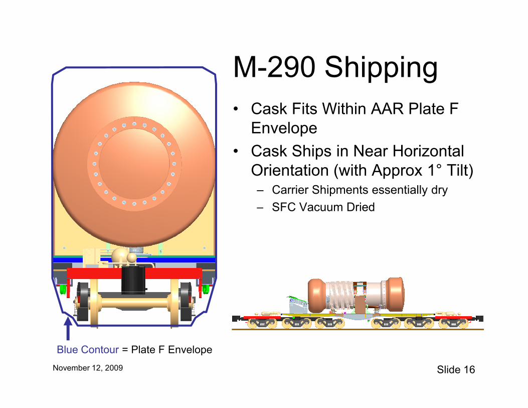
M-290 Shipping• Cask Fits Within AAR Plate F
Envelope
• Cask Ships in Near Horizontal Orientation (with Approx 1° Tilt)– Carrier Shipments essentially dry
SFC V D i d
Slide 16November 12, 2009
– SFC Vacuum Dried
Blue Contour = Plate F Envelope

M-290 Lifting & HandlingLifting Plateattaches toTop Dome
• M-290 is upended and lifted through the Top Dome
• Pivoting hardware attached to bottom dome for upending
• Handling equipment removed for shipment
Slide 17November 12, 2009
Upending Hardware attaches to Bottom Dome
The M-290 is designed so that, for normal operations, it can only be lifted with the domes attached.
Upending stand is attached to railcar

SFC Design Overview• All-welded canister• Planned for Direct Placement in Geologic Repository• Also used for NRF on-site storage of Spent Fuel
– Storage SAR per 10CFR72 (NRC reviewed Jan. 2001)• Cargoes to Include All Naval Cores
Slide 18November 12, 2009
Temporary Dry Storage at NRF

SFC Design OverviewLeak-Tightness is
assured by robust closure:
- Shear Ring with Seal Welds
- Outer Seal Plate with Seal Welds
Slide 19November 12, 2009
- Vacuum Dried & Leak Tested
- Demonstrated Via Analysis and Testing
- Ductile Type 316/316L steel construction

SFC Design Overview
• Naval Fuel Assembly: most of this spent fuel has been previously shipped
• SFC:– Loaded with spent fuel while Fully Flooded– SFC Vacuum Dried, Backfilled, Leak Tested
Slide 20November 12, 2009
, ,– Analyses will demonstrate Baskets maintain
configuration– Analyses will demonstrate Fuel Assemblies
experience no gross rearrangement
• SFC Meets Intent of ISG 18– seal welds in lieu of structural welds (reviewed by
NRC (Naval Storage SAR))

M-290 Certification Strategy
Topic 2b
Slide 21November 12, 2009
gy

M-290 SARPs
M-290 Core-Independent SARP
M-290 A1W SARP (Core-Dependent)M-290 A1G SARP (Core-Dependent)M-290 A1B SARP (Core-Dependent)
Slide 22November 12, 2009
SFC-in-M-290 SARP: Core-Independent
SFC SARPs (various) – Core-Dependent

M-290 SARPs
• The M-290 Core-Independent SARP evaluates common hardware:– Cask Body, Domes, Containment Cover, and their attachment
systems– Hardware (¼-scale) is tested in the Certification Test Program
• Test Report will be included in the Core Independent SARP
Slide 23November 12, 2009
• Test Report will be included in the Core-Independent SARP
• Core-Dependent SARPs will address specific spent fuel cargoes– Shipments from shipyard to NRF
• A1W canister• A1G and A1B internals
– Shipments from NRF to Geologic Repository• Naval Spent Fuel Canister (SFC)

M-290 SARPs
• All Impact Orientations are Being Evaluated: Top, Bottom, Oblique, Side, and Slapdown– M-290 Peak Axial Deceleration: 125g hot, 130g cold– M-290 Peak Lateral Deceleration: 250g hot, 310g
cold (at cask ends)
Slide 24November 12, 2009
cold (at cask ends)– Analyses performed using a combination of hand
calculations and explicit, dynamic finite element codes
• Static analyses use orientation-specific Dynamic Load Factors (DLF)
• FEA codes: LS-DYNA and ABAQUS

Closure Regions for Canister-Based & non-Canister-Based Configurations
Understanding the Closure region will help in understanding the Containment and Confinement Posture.
Slide 25November 12, 2009
Closure HeadRestraint PlateCanister Closure
Canister-Based Configuration non-Canister-Based Configuration

Layered, Defense-in-Depth Design
Layer Canister-Based Not Canister-Based
1 Cladding achieves Containment of Primary Fission Products
- Battle-Worthy Shock-Tested Naval Fuel Assembly
- Either previously shipped or same as previously shipped cross-country (e.g., A1G: M-140)
2 Canister Closure, combined with Restraint, achieves Confinement
- Shear Ring is identical for Canister-Based & non-Canister-Based
Closure Head achieves Confinement (operational containment boundary, but
Containment at more than one level
Slide 26November 12, 2009
y,seals not relied on for Certification)
3 Containment Cover contains releasable crud Containment Cover contains releasable crud
3a. SFC Closure achieves Containment (contains releasable crud): Shear Ring with seal welds plus Outer Seal Plate with seal welds
4 M-290 Cask and Domes: support and protect all of the above levels

M-290 Approach Relative to ISG-19
ISG-19 Guidance M-290 Approach1. Approval based on reconfigured fuel, with water inleakage – This is the primary approach that the NNPP is pursuing.
Bounding or credible reconfiguration NNPP will use either of these approaches for different M-290 cargo. A1W: 2nd approach. (Note that NNPP has extensive data for irradiated hydrided cladding material properties to support the conclusion of subcriticality.)
Reconfiguration based on actual structural & material behavior
2 Approval based on moderator exclusion
Slide 27November 12, 2009
2. Approval based on moderator exclusion - NNPP will demonstrate the following as part of its overall defense-in-depth approach. NNPP may pursue a moderator-exclusion-based approval for SFC cargo.
Demonstrate water-tight barrier subsequent to hypothetical accidents.
NNPP will demonstrate by analysis that the
M-290 maintains its (mechanical) seal.
Welded canister scale-model drop* of canister with impact limiter, with before-&-after leak testing
SFC only: welded canister: scaled testing will demonstrate SFC stays sealed. (note: seal weld vice ISG-19 structural weld)
Bolted closure scale-model drop* of cask with bolted closure & impact limiter, with before-&-after leak testing
Scale-model testing of M-290 will demonstrate that its bolted closure maintains its seal.
* ISG-19 objective: “Physical test of scaled [canister/bolted closure] to provide added assurance of moderator exclusion under accident conditions.”

Sub-criticality Assessment
• Sub-Criticality Demonstrated for:– Normal Conditions: optimum moderation of
Cask and Canister
– Post-accident: Moderation to the most
Slide 28November 12, 2009
Post accident: Moderation to the most reactive credible extent consistent with the package damaged condition
• Carrier defueling cargoes: moderated spent fuel
• SFC cargoes: flooded Cask and un-moderated cargo
• SFC cargoes: (additional defense-in-depth) flooded cask and moderated cargo
Structural Analysis Approach
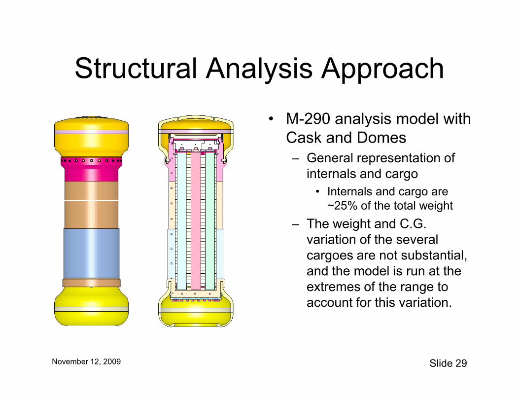
• M-290 analysis model with Cask and Domes– General representation of
internals and cargo• Internals and cargo are
Slide 29November 12, 2009
~25% of the total weight
– The weight and C.G. variation of the several cargoes are not substantial, and the model is run at the extremes of the range to account for this variation.

Drop Angle Orientations
• The cask model is evaluated for Top, Bottom, Side, and the oblique angles in
Slide 30November 12, 2009
between, including Slapdown

Acceleration Curves
• Explicit, dynamic finite element analysis (FEA) of the Cask/Dome model produces acceleration curves:Local acceleration
curves (LA##)
Slide 31November 12, 2009
– Rigid body curves, and
– Local acceleration curves (account for cask flex)
• These curves are used for “driving” the submodels.
curves (LA##) generated at the points identified

Structural Submodels
• Regions of interest that require finer FEA mesh are evaluated with
submodel of closure region
-1.00E+04
0.00E+00
1.00E+04
2.00E+04
3.00E+04
4.00E+04
5.00E+04
0.0000 0.0050 0.0100 0.0150 0.0200 0.0250 0.0300 0.0350
Slide 32November 12, 2009
submodels– Closure region
– Cargo and internals
submodel of internals and cargo
-1.00E+04
0.00E+00
1.00E+04
2.00E+04
3.00E+04
4.00E+04
5.00E+04
0.0000 0.0050 0.0100 0.0150 0.0200 0.0250 0.0300 0.0350 0.0400

Analysis Conditions
• These considerations figure into the total number of analysis models and runs– Drop Orientation
Deceleration (rigid body local acceleration)
Slide 33November 12, 2009
– Deceleration (rigid body, local acceleration)• If one is clearly more limiting, run only that.
– Temperature (hot, cold)
– Material strength• Domes: min/max variability (effect on deceleration)
• Spent fuel: irradiation effects

M-290 Certification Test Program
• ¼-scale M-290• Supplements M-290 Cask design and SARP analysis• Supports Cask certification for compliance with 10CFR71• Will execute drop tests in 2010-2011 (1st drop: Oct. 2010)
– Based on Limiting Orientations
Slide 34November 12, 2009
Based on Limiting Orientations– Seven 30 foot plus one or two 40 inch puncture drops– A1G-based and SFC-based internal configurations– Includes helium leak testing of cask and SFC– Based on previous testing experience with M-140 Shipping
Container– Supplemented by previous M-290 proof-of-principle drop tests
(following slides), which validated M-290 design as viable

¼-scale Drop Tests
• Testing performed at Sandia National Lab
• Included helium leak testing to ANSI N14.5
• 6 drops: top, top corner, and slapdown (same
M-290 Proof-of-Principle
Slide 35November 12, 2009
and slapdown (same cask used in all tests)
• Leak-tightness demonstrated for all tests
• Representative A1G and SFC Cargo Used– SFC remained leak-tight for
all drops in M-290

¼-scale Drop Tests
• Measured Deformations Agree Well with Analytical Model
Top Drop
M-290 Proof-of-Principle
Slide 36November 12, 2009
– Analytical model deformations slightly exceed measured data
Slapdown
Shaded Image = Analysis ResultRed Dots = Measurement Data
¼-scale Drop Tests
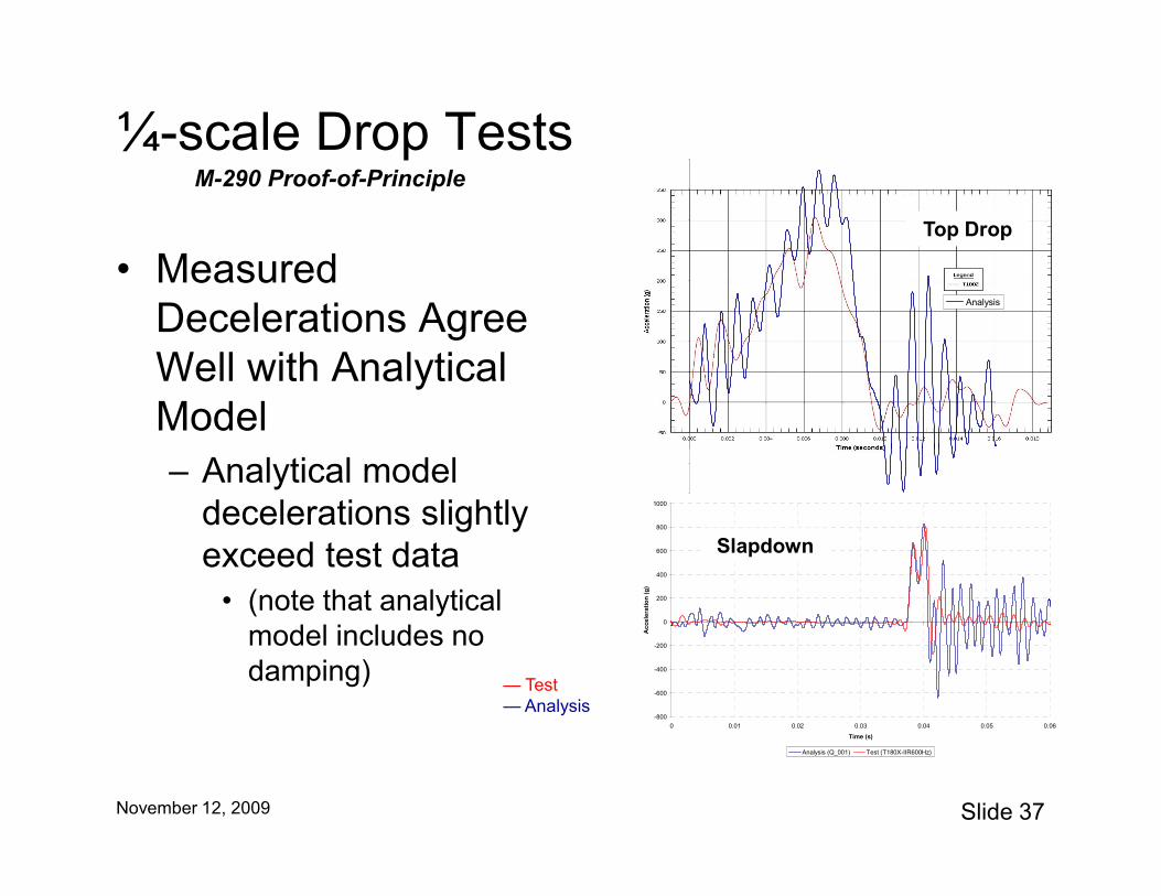
• Measured Decelerations Agree Well with Analytical Model
Analysis
Top Drop
M-290 Proof-of-Principle
Slide 37November 12, 2009
– Analytical model decelerations slightly exceed test data
• (note that analytical model includes no damping)
-800
-600
-400
-200
0
200
400
600
800
1000
0 0.01 0.02 0.03 0.04 0.05 0.06
Time (s)
Ac
cele
rati
on
(g
)
Analysis (Q_001) Test (T180X-IIR600Hz)
Slapdown
— Test— Analysis


![K attakhanov m s., T reatise X X V , B aburiyya [F . 290 b]vika/dissertation/katta/25... · K attakhanov m s., T reatise X X V , B aburiyya 1469 [F . 290 b]!"#$%& '(#$%& )*%& !+,.%](https://static.fdocuments.us/doc/165x107/607ab1cd4530501da566b174/k-attakhanov-m-s-t-reatise-x-x-v-b-aburiyya-f-290-b-vikadissertationkatta25.jpg)


