
The LNM Institute of Information Technology, Jaipur · Compression brass cable gland wherever used...
26
The LNM Institute of Information Technology, Jaipur (Deemed University) TENDER NOTICE Sealed tenders are invited for the supply, installation, testing & commissioning of Air- Conditioning machines and allied works on “turnkey basis”. You can submit your sealed offer at the following address by Speed-post/Registered Post/By-hand (but not by Courier) before 22.03.16 Technical and commercial bids shall be submitted to the undersigned before the time and date given below: Finance & Purchase Officer The LNM Institute of Information Technology, Gram – Rupa Ki Nangal, Post – Sumel, Via – Jamdoli, Jaipur- 302031 Phone: 0141 5191733, Fax: 0141 5189214 Email: [email protected] Technical bid shall include (sealed in separate envelope): signed and stamped copies of technical specifications & approved make of materials, list of past installations with contact details. Financial bid shall include (sealed in separate envelope): prices of all machines and parts as given in the attached Financial Bid (Bill of Quantity). Prices shall be FOR SITE and inclusive of all taxes. Nothing extra shall be paid for any item other than the quoted price. Last Date of Submission : March 22 nd 2016
Transcript of The LNM Institute of Information Technology, Jaipur · Compression brass cable gland wherever used...

The LNM Institute of Information Technology, Jaipur (Deemed University)
TENDER NOTICE
Sealed tenders are invited for the supply, installation, testing & commissioning of Air-Conditioning machines and allied works on “turnkey basis”. You can submit your sealed offer at the following address by Speed-post/Registered Post/By-hand (but not by Courier) before 22.03.16 Technical and commercial bids shall be submitted to the undersigned before the time and date given below:
Finance & Purchase Officer
The LNM Institute of Information Technology,
Gram – Rupa Ki Nangal, Post – Sumel,
Via – Jamdoli, Jaipur- 302031
Phone: 0141 5191733, Fax: 0141 5189214
Email: [email protected]
Technical bid shall include (sealed in separate envelope): signed and stamped copies of technical specifications & approved make of materials, list of past installations with contact details. Financial bid shall include (sealed in separate envelope): prices of all machines and parts as
given in the attached Financial Bid (Bill of Quantity). Prices shall be FOR SITE and inclusive of all taxes. Nothing extra shall be paid for any item other than the quoted price.
Last Date of Submission : March 22nd 2016
TECHNICAL SPECIFICATIONS
(ELECTRICAL WORKS)
TECHNICAL SPECIFICATIONS
FOR
EXTERNAL ELECTRICAL WORKS
SWITCH BOARDS (CUBICAL TYPE)
The switch board shall be metal clad, totally enclosed, single front, floor mounted, cubical type for use on 415 volts 3 phase, 50 cycles system with a fault level withstand of 50 K A RHS symmetrical. The switch board shall be made up of the requisite vertical sections. Which when coupled together shall form continuous dead front switch boards of dust and vermin proof construction.
All panels and cover shall be properly fitted and square with the frame. Holes in the panel shall be correctly provided and tapped into on adequate thickness of metal or provided with nuts, for convenient fixing of screws. Self threading of screw shall not be used in the fabrication of the panels. All doors shall be provided with neoprene gaskets. Each vertical panel structure shall contain a cable way alloy of adequate width with provision for suitable cable supports. The cable compartment shall have hinged door. There shall be a separate gland plate for each cable entry so that there will not be dislocation for already wired circuits when new feeders are added. The entire switch board shall be factory assembled.
The panel shall include the required number of MCB / FSU and breakers as per item, copper bus bars as per requirement and item of work with separate neutral bar & earth bars of coppers.
The units should be arranged in their formation to provide a compact switch board having a pleasing appearance. The minimum depth of switch board shall be 300mm and the height be restricted to 200mm. Steel sheet hinged lockable doors shall be duly interlocked with fuses witch unit to prevent opening of the panel when the switch is in 'ON' position. Safety interlocks shall be provided also. All the MCCB's shall be provide with vertical operation.
All indicating instruments shall be of the flush mounting industrial pattern conforming to the requirement of IS:1248, indicating lamps shall be of the neon type. Separate compartment shall be provided for accommodating instruments, indicating lamps, control contractors and fuses etc. these shall be accessible for testing and maintenance without any danger of accidental contact with line parts of the circuit breakers, unit’s bus bar and connections.
Horizontal wire way with screwed cover shall be provided at the top to take interconnecting control wiring between different vertical sections. Control wiring shall be of copper conductor and shall be color coded for easy identification of circuits. This should be of not less section than 2.5 sq mm not more than two connections shall be made off anyone terminal.
All cable shall be neatly bunched and shall be secured to wiring cradles. All outgoing cables shall be fitted with identification ferrules at each end. Circuit diagram showing the arrangement of circuits shall be pasted on the inside of panel door and covered with transparent plastic sheet. Knockout holes of appropriate size and number shall be provided with panel in conformity with the location of incoming and outgoing cables/conduits. Facility shall be provided for termination of cables from both above and below the panel. Where cables enter from below, cable eyes shall be provided for connections to main earth. The earth bar shall run within the base frame.
All steel material used in the construction of the switch board should have undergone a rigorous rust proofing process comprising alkaline degreasing, desiccating in dilute sulfuric acid and recognized Phosphating process. The steel work should then receive the coats of oxide premier before final coat of staying synthetic enamel paint of approved shade.
Engraved plastic labels shall be provided indicating the feeder details. Danger notice plate shall also be provided as per I.E. Rules. Adequate provision shall be made for escape of hot gases by providing louvers. The louvers shall be located as to direct the hot gases away from the operating personnel and shall be covered with a perforated sheet having less than 1 mm diameter perforations to prevent entry of vermin. All nuts, bolts and washers shall be cadmium plated. Each panel incomes section shall be provided with voltmeter 0-500 volts with 3-way on and off selector, switch, ammeter of appropriate range with selector switch as per the bill of material in the tender. DISTRIBUTION BOARDS
Distribution boards shall be of standard make with MCB's as per approved makes and factory assembled with latching covers flush lock. Ample clearance between the conductors of opposite pole, between conductors and sheet steel body shall be maintained in order to obviate any chance of short circuit. Removable conduits entry plates shall provided at top and bottom to facilitate drilling holes at site to suit individual requirements. The MCB's shall be mounted on a high grade rigid insulating support and connected by electrolytic copper bus bars. Each incoming MCB isolator shall be provided with solder less cable sockets for crimping. Phase separation barriers made out of are resistant materials shall be provided between the phases. Bus bars shall be color coded for phase identification.

Distribution boards shall be recessed in wall niche or if required mounted on the surface of the wall with necessary clamp bolts etc. as required at a height not exceeding 1600 mm from finished floor level. Distribution board shall be provided with proper identification name plate, danger mark etc.
All the distribution boards shall be marked 'lighting',' power' or 'Emergency' as the case may be. Each D B shall be provided with a circuit list giving details of each circuit. All the outgoing circuit wiring shall be provided with identification ferules giving the circuit number and phase.
Each distribution board shall have a separate neutral connection bar and a separate earth connection bar mounted within the board each having the same number of terminals as the total number of outgoing individual circuits from the distribution board. Suitable earth terminal shall be provided on the distribution board for bonding to earth.
Distribution boards shall be duly rust inhibited through a process of degreasing, acid picking Phosphating and spray primer. The entire board shall be rendered dust and vermin proof with necessary sealing gaskets.
MCB's shall have quick make and break non-welding silver alloy contacts, both on the manual and automatic operation. MCB's shall be of thermal magnetic type with inverse time-delay over-current tripping, having a short circuit rupturing capacity of 9KA. In case of, multiple breakers the tripping must be on all the poles and shrouded, wherever MCB isolators are specified they are without the tripping elements. Necessary adopter box of suitable size shall be provided to facilitate the wiring and nothing shall be payable on this account.
L.T. CABLE
L.T. cable shall be of aluminum/copper conductor as instructed by project engineer / Project-in-charge, FRLS type PVC insulated, PVC sheathed steel tape armored construction conforming to IS- 1554 of 1100 volts grade. The aluminum conductors shall be stranded for sizes above 16sq mm and sector shaped standard conductors shall be used for heavy sizes. As far as possible, cables shall be supplied in drums. Cables supplied shall bear manufacturer's identification marks at regular intervals.
CABLE TERMINATIONS
Cable leads shall be terminated at the equipment terminals by means of crimp type soldieries connectors as manufacture by MIS. Dowel Electro works. Crimping shall be done by hydraulically operated tools and conduction jelly shall be applied. On the conductor Insulation of the leads should be removed immediately before the crimping. Conductor

surface shall be cleaned and shall not be left open for long, prior to crimping to prevent oxidation. Control cables of single strand cables may be directly terminated on to the terminals. Straight through joint if required shall be made by rising epoxy resin cold setting compound type Tripoli of M seal brand. Compression brass cable gland wherever used shall be of current size for cable and terminations. No oversize cable glands shall be used. The gland must grips the armor of the cable firmly, so that in the event of ground movement no undue stress is transferred to the cable conductors. The gland must establish good electrical contact between cable armor, lead sheath and body of switcher. Identification ferrules indication the circuit shall be used for incoming and outgoing cables.
CABLE WORK IN UNDER GROUND
While laying underground cables care should be taken so that any underground structure such as water pipes, sewerage lines, etc. are not damaged. Any telephone or other cable coming in the way shall be properly protected as per instructions of Architect. All cable routes shall be carefully measured and cable cut to the required lengths leaving sufficient length for the final connection of the cable. All cable trenches entering sub- stations plants etc. shall be effectively sealed after installation of cables to avoid entry of water.
The L.T. cables shall be laid not less than 75 cm below ground level in a trench 35cm wide minimum .The depth of the trenches shall be uniform throughout. A bed of 17 cm dry sand shall be load before he cable is laid.
When the cable is properly straightened and laid in the trench, it should be covered all around 8mm thick layer of sand. Approved cable indicators shall be fixed at suitable distances along the route of the cable.
Unless otherwise specified the cables shall be protected by second class bricks of not less than 22.5x 10.0x7 cm or stone tiles or any other approved material placed on sides and top of the cable to form a channel throughout the length.
Spun reinforced concrete pipes shall be provided for all road crossings. The size and nature of the pipe shall be decided by Architect and shall not be less than 10cm in diameter for a single cable and not less than 20cm for more than one cable. these pipes shall be laid in the ground with 10cm thick bed of cement concrete 1:5: 1 0 and may be loose jointed. The top surface of pipe shall be at minimum depth of 90cm from the ground level when laid under the roads/ pavements.
Filling of trenches shall be done after the sand cushioning and laying of tiles are carried out to the satisfaction of a architect, where road bergs or lawns have been cut of Keri stones displaced the same shall be repaired to the satisfaction without any extra cost.

CABLE WORK
LAYING OF CABLES OVER DUCTS/ WALL/TRAYS:-
Cable ducts should be of such dimension that the cables laid in it do not touch one another .If found necessary the cable shall be fixed with clamps on the walls of the duct .Cables shall be laid on the walls/on the trays as required using suitable clamping/ fixing arrangement as required. Cables shall be neatly arranged on the trays in such manner that cross-crossing is avoided and final take off to switch gear is easily facilitated.
All cables will be identified close to their termination point by cable number as per circuit schedule. Cable numbers will be punched on 2mm thick aluminum strips and securely fastened to the cable. In case of control cables all covers shall be identified by their wire numbers by means of PVC ferrules. For trip circuit identification additional red ferrules are to be used only in the switch gear/ control panels, cables shall be supported so as to prevent appreciable sagging. In general distance between supports shall not be greater than 600mm for horizontal run and 750mm for vertical run.
TESTING OF CABLES:-
After laying and jointing work is completed, a high voltage test should be applied to all cables to ensure that they have not been damaged during or after the laying operation and that there is no fault in the jointing. For 33KV XLPE cable high pot test shall be done at site by 50KV system and nothing extra shall be payable. Cable for use on low and medium voltage system (1.1 K V grade cables) should with stand for 15 minutes a pressure of 3000 volts DC applied between conductors and also between each conductor and sheaths .In the absence of " Pressure testing facility" it is sufficient to test for one minute with a 1000 volts insulation tester In case, the test results are unsatisfactory the cost of all repairs and replacement and relaying will be made good by the contractor. Nothing shall be payable for conducting high pot test.
CABLE TRAYS:
Cable trays shall be ladder type fabricated out of mild steel/ slotted angles and flats of required width as per design. Bends shall be prefabricated the cable tray shall be primed and painted with two coats as approved by Engineer - In - Charge. Suitable provision shall be made where a tray crosses expansion joints. The width of the tray shall allow for a suitable separation between cables the design shall allow for adequate bending reduces for the sizes of cables.
The tray shall be suspended from the sophist of the concrete slab by means of approved steel hangers spaced at a distance of not more than 100cms. Suitable bushes shall be

provided where cables pass through apertures in the tray. Cable must securely fixed to the tray with fasteners .In routing, necessary barriers and spacing shall be maintained for cables of different voltages in case they lie side by side. Telephone cables shall cross the power cables only at about right angle and these two shall not run in close proximity. Full details of the tray shall be approved by the site engineer before fabrication. Earth continuity shall be maintained between each section of cable tray and each total run of tray shall be effectively bonded to the nearest earth continuity conductor. AII nuts and bolts used shall be of galvanized steel.
EARTHING
All non-current carrying metal parts of electrical installation shall be earthed as per IS:3043-1986 with latest amendments. All metal conduits, cable sheathes, switch gear, DB's, light fixtures, equipments and all other parts made of metal shall be bonded together and connected to earth electrodes. Earthling shall be in conformity with provision of rules 32, 61, 62, 67& 68 of Indian electricity rules (1956).
All earthing conductors shall be of high conductivity copper, GI and shall be protected against mechanical damage. The cross sectional area of earth conductors shall not be smaller than half that of the largest current carrying conductor. However the contractor shall use the sizes specified in the bill of quantities.
All fixtures and socket outlets, fans, switch boxes and junction boxes, etc. shall be earthen with bars copper wire as specified in the item of work. The earth wire ends shall be connected with solder-less bottle type copper lugs.
All single phase 0 B's up to 60Amps shall be earthen with 8 SWG GI wire as per item of work.
All 3 phase switch boards up to 100Amps rating shall be earthen with 2Nos. Separate and 25 x 3mm GI strip as per item of work.
All switch boards of ratings more than 100Amps and above shall be earthen with 2Nos. Distinctive separate 25 x 6mm GI strips as per item of work.
All the earth wires in switch boxes, DB's and light fixtures/fans shall be provided with green color sleeving.
Main earth bus shall be taken from the L T. Switch board to earth electrodes. The electrical resistance of earthing conductors shall be low enough to permit passage of fault current necessary to operate fuse or circuit breaker and shall not exceed 2 ohms.
A-PLATE EARTHING
The earthing electrode shall consist of GI plate (60cm x 60cm x 6mm l tinned copper plate 60cm x 60cm x 3mm) as specified in item of work. Galvanizing of the plate shall conform to relevant Indian Standard. The plate electrode shall be buried in the ground with its faces vertical and top not less than 4.5m below GL. The earth plate pipe shall be buried in the ground below the permanent moisture level but not less than 4.5m below ground level. The plate shall be filled with charcoal dust and common salt filling extending up to 15cm around it on all sides. There shall be a 20 mm dia., medium class GI pipe running from top plinth plate up to the ground level for watering pipe. The top of the pipe shall be provided with a funnel and a GI mesh screen for washing the earth. This will be housed in a masonry sump with cement plastering not less than 30cm deep. M. S . Frame heavy duty with hinged cover and locking arrangement shall be suitably provided over the sump. The earthing link from electrode onwards shall be suitably protected from mechanical injury by GI pipe. The portion of this protection pipe within the ground shall be buried at the least 30cm deep (to be increased to 60cm in case of road crossing and pavements). The portion within the building shall be recessed in walls and floors to adequate depth. In the case of plate earth electrode, the earthing load shall be securely bolted to the plate with two bolts, nuts check nuts and washers. In case of pipe earth electrode, It should be counted by means of a 'through' connection with the earth lead with electrode shall be GI brass in case of copper plate electrode.
The electrical resistance of earthing conductors shall be low enough to permit passage of fault current necessary to operate the fuse or circuit breaker and shall not exceed 2 ohms.
PIPE EARTHING
The earthing electrode shall consist of GI pipe of 40mmdia. and4.5m length B-class or as described under schedule of quantities. Galvanizing of the pipe shall conform to relevant Indian Standards. The top of the pipe shall be provided with a funnel and a GI screen for watering the earth. This will be housed in a masonry sump not less than 30cm square and 30cm deep. A heavy duty MS frame with hinged cover and locking arrangement shall be suitably provided over the sump as approved by the Engineer In Charge.
GI pipe electrode shall be cut tapered at the bottom and provided with holes of 10 mm dia., drilled not less than 7.5cm from each other. The pipe shall be buried in the group vertically with its top not less than 20cm below ground level. The earthing lead from electrode onwards shall be suitably protected from mechanical injury by GI pipe within ground and the portion within the building shall be recessed in walls and floors to adequate depth. The earthing lead shall be connected by means of a through bolt, nuts and washers and cable socket. All materials used for connecting the earth lead with the electrode shall be GI The earth pit depth shall not be less than 4.8m.

No earth pit shall be fixed within 2m of a wall or foundation. Efforts shall be made to locate them in grass lawns or near flower beds or water taps. The distance between two earthing stations shall be at the least 2m.
SF6 / VCB RMU TECHNICAL SPECIFICATION OF 11KV SF6 / VCB METAL ENCLOSED, OUTDOOR RING MAIN UNIT (RMU) (IEC standard equipment) SCOPE OF SUPPLY This specification covers design, manufacture, shop testing, inspection, packing, delivery to site, erection, testing and commissioning of 11 kV, Metal Enclosed, panel type, extensible Outdoor SF6 RING MAIN UNIT (RMU) fully type tested according to IEC 60298 standards. This RMU should be complete with all components necessary for its effective and trouble free operation along with associated equipment etc. such components should be deemed to be within the scope of supplier’s supply. The design of the switchgear should be exclusive and specific responsibility of supplier and should be comply with current good engineering practice, the relevant codes and recommendation, the project specific requirements. The RMU should be fixed type SF-6, insulated circuit breakers, with O/C & E/F relay for the protection of the transformer. It should be maintenance free equipment, having stainless steel robotically welded enclosure. STANDARDS AND REFERENCE DOCUMENTS Codes and Standards
The RING MAIN UNIT (RMU) should be designed, manufactured and tested according to the latest version of: IEC 60694: Common specifications for high-voltage switchgear and control gear standards. IEC 60298: A.C metal-enclosed switchgear and control gear for rated voltages above 1KV and up to and including 72KV and the IEC Codes herein referred. IEC 60129: Alternating current Disconnector (isolators) and earthing switches IEC 60529: Classification of degrees of protection provided by enclosures IEC 60265: High-voltage switches-Part 1: Switches for rated voltages above 1kV and less than 52 kV IEC 60056: Circuit breakers IEC 60420: High-voltage alternating current switch-fuse combinations IEC 60185: Current transformers IEC 60186: Voltage transformers IEC 60255: Electrical relays

Any other codes recognized in the country of origin of equipment might be considered provided that they fully comply with IEC standards.
The design of the switchgear should be based on safety to personnel and equipment during operation and maintenance, reliability of service, ease of maintenance, mechanical protection of equipment, interchangeability of equipment and ready addition of future loads.
Salient Technical feature of “SF-6 RMU.”
Offered 11KV SF6 / VCB INDOOR/ OUTDOOR, EXTENSIBLE, Ring Main Unit (RMU), comprising of 2 Nos. 630A Load break Switches, 1No. 630 A SF6 / VCB “T”OFF Circuit Breaker with O/C & E/F Relays. (A) Load break switch (630A)
Load break switch should have the following - Manually operated 12 KV, 630A Load Break switch and Earthing Switch
with making capacity - “Live Cable”LED Indicators thru Capacitor Voltage Dividers mounted
on the bushings. - Mechanical ON/OFF/EARTH Indication - Anti-reflex operating handle.
Cable Testing facility without disconnecting the cable terminations, cable joints and terminal protectors on the bushings Cable terminations- Cable boxes suitable for 1 X 3C x 300 sq mm XLPE Cable with right
angle Cable Termination Protectors.
(B) Circuit Breaker. (630A) Circuit Breaker should have the following: - Manually operated 630A SF6 / Vacuum circuit breaker and Ear thing
Switch with making capacity - Mechanical tripped on fault indicator - Auxiliary contacts 1NO and 1NC - Anti-reflex operating handle - “Live Cable” LED Indicators thru Capacitor Voltage Dividers mounted
on the bushings. - O/C + E/F self powered relay - Shunt Trip circuit for external trip signal - Mechanical ON/OFF/EARTH Indication - Cable boxes suitable for 1 X 3C x 300 sq mm XLPE Cable with right
angle Cable Termination / protectors / boots.

OUT DOOR RMU
1. Hermetically sealed metallic Epoxy / Stainless steel enclosure for OUT DOOR RMU application. The manufacturers shall conform the normal current ratings mentioned in GTP at 45 deg. Ambient without derating.
2. Enclosure with I.P.54 standard protection. 3. Offered RMU must be extensible. 4. Cable boxes shall be on Front / side/rear sides. 5. Three way type, with two nos. of 630 Amp isolators and 200 Amp. ”T”-off circuit
breaker. 6. RMU ENCLOSURE MUST BE SHIELDED AGAINST SOLAR IRRADIATION AND TESTED
FOR AMBIENT OF 45 / 50 DEGREE C.
The manufacturers shall confirm the normal current ratings mentioned in GTP at 50 deg. Ambient without derating. DIELECTRIC MEDIUM SF6 / VCB GAS shall be used for the dielectric medium for 11KV/22KV RMUS in accordance with IEC376. It is preferable to fit an absorption material in the tank to absorb the moisture from the SF6 / VCB gas and to regenerate the SF6 / VCB gas following arc interruption. The SF6 / VCB insulating medium shall be constantly monitored via a temperature compensating gas pressure indicator offering a simple go, no-go indication. TECHNICAL AND GUARANTEED PARTICULARS. DESIGN CRITERIA Service conditions The offered switchgear and control gear should be suitable for continuous operation under the basic service conditions indicated below. Installation should be in normal indoor conditions in accordance with IEC 60694. Ambient temperature -1deg C to +55deg C Relative humidity up to 95% Altitude of installation up to 1000m, IEC 60120 General structural and mechanical construction The offered RMU should be of the fully arc proof metal enclosed, free standing, floor mounting, flush fronted type, consisting of modules assembled into one or more units. Each unit is made of a cubicle sealed-for life with SF6 / VCB and contains all high voltage components sealed off from the environment.
The overall design of the indoor switchgear should be such that front access only is required. It should be possible to erect the switchboard against a substation wall, with HV and LV cables being terminated and accessible from the front. The units should be constructed from 3 mm thick stainless steel sheets. The design of the units should be such that no permanent or harmful distortion occurs either when being lifted by eyebolts or when moved into position by rollers. For outdoor RMUs a weather proofing process shall be carried out. Sheet metal must be grit blased / thermally sprayed and polyurethane painted with about 70 micron thicknesses, to achieve outdoor worthiness and corrosion proof. -RMU ENCLOSURE MUST BE SHIELDED AGAINST SOLAR IRRADIATION AND TESTED FOR AMBIENT OF 45 / 55 DEGREE C WITHOUT DERATING OF THE EQUIPMENT. The cubicle should be having a pressure relief device. In the rare case of an internal arc, the high pressure caused by the arc will release it, and the hot gases is allowed to be exhausted out at the bottom / top / rear of the cubicle. A controlled direction of flow of the hot gas should be achieved. The switchgear should have the minimum degree of protection (in accordance with IEC 60529) - IP 67 for the tank with high voltage components - IP 2X for the front covers of the mechanism - IP 3X for the cable connection covers - IP 54 for the outdoor enclosure.

SPECIAL CONDITIONS
SPECIAL CONDITIONS
1. All electrical work shall be carried our in compliance with specifications given hereunder in this section and in compliance with Indian Standard specifications and Indian Electricity Act and Rules in force. The works shall also conform to any special requirement of Local State Electricity Board. If any case, the above-mentioned rules, regulations etc. are not in accord, the division of the consultant Engineer-in-charge regarding rules to be followed or manner of execution of work shall be final and binding. The work shall be executed under the direct supervision of person holding a certificate of competency issued by the State Government (Chief Electrical Inspector) for the type of works involved in conformity with the best methods of modern engineering practice and to the entire satisfaction of the Consultant / Engineer-in-Charge. The contractor has to submit the test report at various stages of completion as per requirement of the client
1.1.1 Work shall be executed through licensed electrical contractor approved by the Owner I Architect I Electrical Inspect (Directorate of safety, Govt.)
1.2 These special conditions of contract shall be read in conjunction with the General Conditions of Contract, Schedule of Quantities, Technical Specifications, Drawings and other documents relating to the work and shall have preference over laid down general conditions and specifications.
1.3 Notwithstanding the sub-division of the documents into these separate sections and volumes, every part of each shall be deemed to be supplementary and complementary to every other part and shall be read with and into the contract, so far as it may be practicable to do so.
1.4 The contractors shall mobiles and employ sufficient resources to achieve the detailed schedule with in the broad frame work of the accepted methods of working and safety. The contractor shall provide everything necessary for the proper carrying out of the work, including tools, plants and other materials.
1.5 No additional payment will be made to the contractor for any multiple shift work or other incentive methods contemplated by him in his work schedules even though the time schedule is approved by the consultant /Engineer-in-Charge.
1.6 The work shall be executed as per the programmer drawn or approved by the Consultant and it shall be so arranged as at site. No claim for idle labour shall be entertained nor shall any claim on account of the delay in the completion of the building work to be tenable except extension of time secured by the contractor as stated elsewhere.
1.7 The contractor shall permit free access and afford normal facilities and usual conveniences to other agencies or departmental workman to carry out connected work or other work services under separate arrangements. The contractor will not be allowed any extra payment on this account.
1.8 All soil, filth or other matter of any offensive nature taken out of any trench, sewer drain, cesspool or other place shall not be deposited on the surface, nut shall at once at carted away by the contractor free of charge to a suitable pit or place to be provided to him.
1.9 The contractor shall provide all equipment, instrument labor and such other assistance required, by the Engineer-in-Charge for measurement of the work, materials etc.
MATERIALS
All materials, equipment's, fittings and fixtures used in electrical works shall conform to the attached list of approved make of materials.
All material shall be new, soundly and robust in construction and well finished. Surplus material after completion of work shall be taken back by the contractor and the cost shall be recovered if the advance payment has been made earlier by the client.
Unless otherwise stated in the conditions of contract, of contract, samples of all materials, fittings and fixtures to be supplies by the contractor shall be submitted to the consultant for his approval. The contractor shall not commence the work until the samples are approved, in writing from the consultant.
The contractor shall ensure that all the materials incorporated in the work are identical in all respects with the approved sample. All samples not destroyed in testing shall be returned to the contractor after completion of contract. No payment shall be made for samples destroyed in testing.
CLARIFICATIONS OF DISCREPANCIES
4.1 In case of any discrepancy between specifications and drawings etc. or disputes in respect, the interpretation and decision of the Engineer/ project-in-Charge shall be final and binding.

MISCELLANEOUS
5.1 After completion of the work the whole installation shall be tested by the contractor in the presence of the Engineer/ Project-in-charge. The tests shall comply the following I.E.E. Regulations and shall be submitted along with the final bill.
a) The result of the insulation test shall comply with the I.E.E. Regulations 1101 to 11 08A and 1008 bas may be applicable.
b) Test shall be carried out to ascertain that all the non-linked SP switches have been connected to the phase conductor.
c) The continuity test of the earthling system shall comply with I.E.E. Regulations 1108 to 11109 to the latest addition.
If the results of the above tests does not comply with the I.E.E. Regulations, the contractor shall be bound to rectify the faults so that the required results are obtained. The contractor shall be responsible to provide all the necessary testing instruments, such as megger, insulation tester, earth tester, multi meter, AVO meter etc. for carrying out the above tests. 10% of the installation cost will be deducted from the bill if the IR and earth resistance tests not carried out in presence of Engineer-in- Charge.
5.3 The work will not be considered as complete and taken over by the Employer till all the components of the work after being completed at site in all respects have been inspected / tested by the Engineer-in-Charge to his entire satisfaction and a completion certificate issued by the Owner’s Representative/Project Engineer/Project-in-Charge to this effect.
5.4 At the completion of the work and before insurance of certificate of virtual completion, the contractor shall submit 3 set of as built drawings with one reproducible of each drawing to Consultant layout drawings drawn at approved scale indicating the complete wiring / cabling / earthling system as installed.
5.5 The contractor will submit a detailed schedule of program of work, on demand of Owner’s Representative/Project Engineer/Project-in-Charge.
WORK AND WORKMANSHIP
6.1 The work shall be of the highest standard, both as regard its design and workmanship. Modern tools and first class, latest techniques shall be employed for its execution.
6.2 Any damage done to the building during the execution of work shall be responsibility of the contractor and it shall be made good by him, at his cost, to the entire satisfaction of the Owner’s Representative/Project Engineer/Project-in-Charge.
6.3 All electrical work shall be executed by skilled electricians under the direct supervision of whole time, fully qualified licensed electrical engineers and supervisors. The contractor shall produce requisite evidence regarding the qualification of the engineer, supervisors and other workers.
6.4 The contractor shall possess all the relevant and valid licensed as per the regulations of the Indian Electricity Rules and the Local Electrical Inspector's requirements.
6.5 The work shall have to be coordinated with the building work and other allied jobs/trades to the entire satisfaction of Engineer-in-Charge/Consultant.
CERTIFICATE OF INSPECTION
7.1 Complete scheme drawing for equipment's/earthling/cable layout/schematic drawing and other details as per requirements shall be prepared by the contractor and got approved by Owner’s Representative/Project Engineer/Project-in-Charge,before commencement of work. Nothing shall be payable to contractor on this account.
7.2 The contractor shall be responsible for getting the installation inspected and approved by the Electrical Inspector and other, local electric supply company, if required.
7.3 The contractor shall obtain and deliver to Owner’s Representative/Project Engineer/Project-in-Charge the certificate of final inspection and approval of the local electrical authorities concerned. The inspection fees etc. shall be borne by the contractor.
7.4 In case of any defects are pointed out by the CEElectricity Authority Inspector, the contractor shall remove these defects at his own cost and arrange for re-inspection or inspection by the electrical inspector, till such time the installation is finally approved and the required certificate is issued. The contractor shall bear all expenses and deposit the necessary fees for subsequent inspections by the CEA.
7.5 Owner’s Representative/Project Engineer/Project-in-Charge shall have full powers to get the material or workmanship etc inspected and tested by an independent agency, at the contractor's expenses in order to ascertain their soundness and adequacy.

7.6 The contractor shall be responsible for obtaining all necessary approvals for entire scheme from State Electrical Board before commencement of the work. All coordination with SEB shall be responsibility of contractor till commissioning and getting electricity in the complex and finally handing over the installation.
7.7 The contractor shall possess State Electrical Contractor's license and all the relevant and valid other licenses as per the regulations of the Indian Electrical Inspector's requirements.
7.8 Any amount to be deposited with the State Electrical Board shall be deposited by the contractor after observing necessary formalities required and take all follow up action for the same. However, the amount so deposited by the contractor will be reimbursed to the contractor on production of necessary and adequate documentary proof/records.
7.9 Working drawing for all system shall be prepared by the contractor & got approved before starting of the work. (H.T. Panel I transformer IL T Panel & Sub Panel I Bus duct and Rising main)
8.0 Shop drawing for all system shall be prepared by the contractor & got approved before starting of the work. (Electrical I Telephone I Paging I T. V I Fire alarm system

Approved Makes

LIST OF APPROVED MAKES OF MATERIALS
1. HEAVY DUTY UPVC PIPE AKG
2. CONDUIT ACCESSORIES. AKG
3. COPPER STRANDED CONDUCTOR PVC INDULATED CABLE 660 V
FINOLEXI RR CABLE
4. DISTRIBUTION BOARDS MCBS. AND ELCBS
MDS(LEGRAND)
5. MOULDED SWITCH AND SOCKET PLATES.
MK (WRAP AROUND PLUS SERIES)
6. LIGHT FIXTURES LUMINAIRES PHILIPS
7. METAL CLAD SOCKET OUTLETS MDS(LEGRAND)
8. EXHAUST FAN CG I BAJAJ
9. TELEPHONE CABLE FINOLEX / RR CABLE 10. SOLDERLESS LUGS I FERRULES LAPP I DOWELL
11. CABLE GLANDS LAPP I COMET
12. L.T. SWITCH BOARD L&T/SCHNEIDER
13. L T. CABLE POLYCAB/HAVELLS 14. TV CABLE POLYCAB/HAVELLS
15. LAN CABLE POLYCAB/HAVELLS
16. MCCB L&T / SCHNEIDER
17. DATA / VOICE Outlet MK (WRAP AROUND PLUS)
18. 11000 VOLTS CABLE LOINTS RAYCHEM / ANY EQUIVALENT / CABLE GLANDS I CABLE LUGS I DOWELLS I
19. METERING ARRANGEMENT L & T I CONZERV / SECURE
20. INDICATING LIGHTS, SELECTOR SWITCHES PUSH BUTTONS, ETC
L &T / CONZERV
21. PROTECTION RELAYS GE POWER CONTROLS I AVKSEGC / CSPC
22. RMU CROMPTON GREAVES
23. HT CABLES POLYCAB
24. HT TERMINATION KITS RPG RAYCHEM NOTE: Above makes of equipment are approved subject to their meeting the specifications.
The contractor however shall seek approval of specific make from Engineer-in-Charge before commencing the work. The decision of Engineer-in-Charge shall be final & binding on the contractor in their respect.
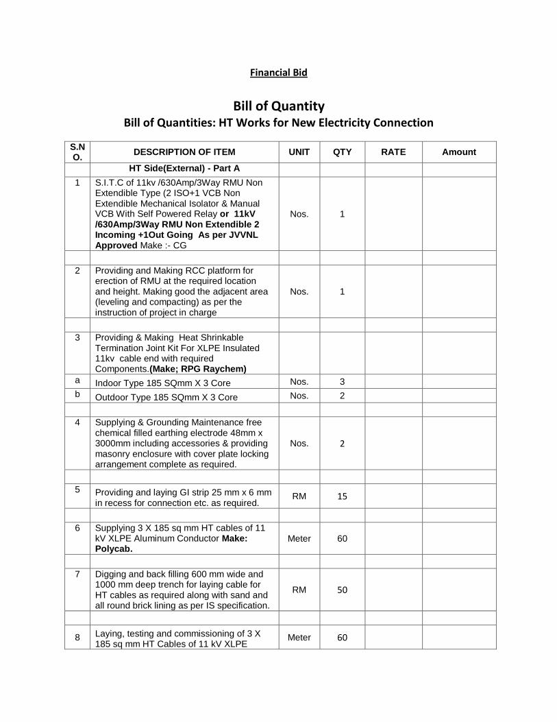
Financial Bid
Bill of Quantity
Bill of Quantities: HT Works for New Electricity Connection
S.NO.
DESCRIPTION OF ITEM UNIT QTY RATE Amount
HT Side(External) - Part A
1 S.I.T.C of 11kv /630Amp/3Way RMU Non Extendible Type (2 ISO+1 VCB Non Extendible Mechanical Isolator & Manual VCB With Self Powered Relay or 11kV /630Amp/3Way RMU Non Extendible 2 Incoming +1Out Going As per JVVNL Approved Make :- CG
Nos. 1
2 Providing and Making RCC platform for erection of RMU at the required location and height. Making good the adjacent area (leveling and compacting) as per the instruction of project in charge
Nos. 1
3 Providing & Making Heat Shrinkable Termination Joint Kit For XLPE Insulated 11kv cable end with required Components.(Make; RPG Raychem)
a Indoor Type 185 SQmm X 3 Core Nos. 3
b Outdoor Type 185 SQmm X 3 Core Nos. 2
4 Supplying & Grounding Maintenance free chemical filled earthing electrode 48mm x 3000mm including accessories & providing masonry enclosure with cover plate locking arrangement complete as required.
Nos. 2
5 Providing and laying GI strip 25 mm x 6 mm
in recess for connection etc. as required. RM 15
6 Supplying 3 X 185 sq mm HT cables of 11 kV XLPE Aluminum Conductor Make: Polycab.
Meter 60
7 Digging and back filling 600 mm wide and 1000 mm deep trench for laying cable for HT cables as required along with sand and all round brick lining as per IS specification.
RM 50
8 Laying, testing and commissioning of 3 X 185 sq mm HT Cables of 11 kV XLPE
Meter 60
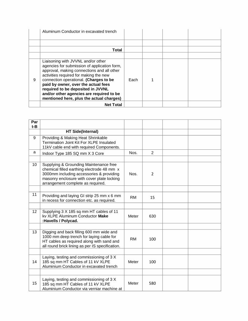
Aluminum Conductor in excavated trench
Total
9
Liaisoning with JVVNL and/or other agencies for submission of application form, approval, making connections and all other activities required for making the new connection operational. (Charges to be paid by owner, over the actual fees required to be deposited in JVVNL and/or other agencies are required to be mentioned here, plus the actual charges)
Each 1
Net Total
Part-B
HT Side(Internal)
9 Providing & Making Heat Shrinkable Termination Joint Kit For XLPE Insulated 11kV cable end with required Components.
a Indoor Type 185 SQ mm X 3 Core Nos. 2
10 Supplying & Grounding Maintenance free chemical filled earthing electrode 48 mm x 3000mm including accessories & providing masonry enclosure with cover plate locking arrangement complete as required.
Nos. 2
11 Providing and laying GI strip 25 mm x 6 mm
in recess for connection etc. as required. RM 15
12 Supplying 3 X 185 sq mm HT cables of 11
kv XLPE Aluminum Conductor Make :Havells / Polycad.
Meter 630
13 Digging and back filling 600 mm wide and 1000 mm deep trench for laying cable for HT cables as required along with sand and all round brick lining as per IS specification.
RM 100
14 Laying, testing and commissioning of 3 X 185 sq mm HT Cables of 11 kV XLPE Aluminium Conductor in excavated trench
Meter 100
15 Laying, testing and commissioning of 3 X 185 sq mm HT Cables of 11 kV XLPE Aluminium Conductor via verniar machine at
Meter 580
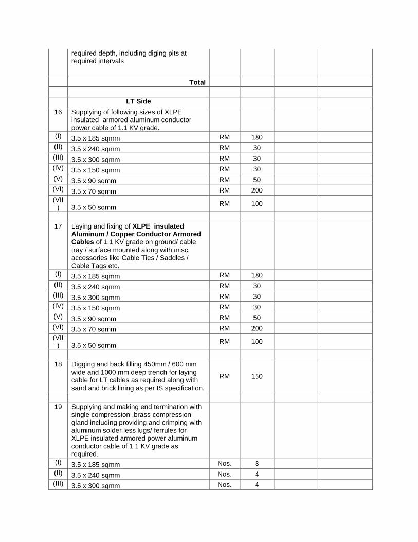
required depth, including diging pits at required intervals
Total
LT Side
16 Supplying of following sizes of XLPE insulated armored aluminum conductor power cable of 1.1 KV grade.
(I) 3.5 x 185 sqmm RM 180
(II) 3.5 x 240 sqmm RM 30
(III) 3.5 x 300 sqmm RM 30
(IV) 3.5 x 150 sqmm RM 30
(V) 3.5 x 90 sqmm RM 50
(VI) 3.5 x 70 sqmm RM 200
(VII) 3.5 x 50 sqmm
RM 100
17 Laying and fixing of XLPE insulated
Aluminum / Copper Conductor Armored Cables of 1.1 KV grade on ground/ cable tray / surface mounted along with misc. accessories like Cable Ties / Saddles / Cable Tags etc.
(I) 3.5 x 185 sqmm RM 180
(II) 3.5 x 240 sqmm RM 30
(III) 3.5 x 300 sqmm RM 30
(IV) 3.5 x 150 sqmm RM 30
(V) 3.5 x 90 sqmm RM 50
(VI) 3.5 x 70 sqmm RM 200
(VII) 3.5 x 50 sqmm
RM 100
18 Digging and back filling 450mm / 600 mm
wide and 1000 mm deep trench for laying cable for LT cables as required along with sand and brick lining as per IS specification.
RM 150
19 Supplying and making end termination with
single compression ,brass compression gland including providing and crimping with aluminum solder less lugs/ ferrules for XLPE insulated armored power aluminum conductor cable of 1.1 KV grade as required.
(I) 3.5 x 185 sqmm Nos. 8 (II) 3.5 x 240 sqmm Nos. 4 (III) 3.5 x 300 sqmm Nos. 4
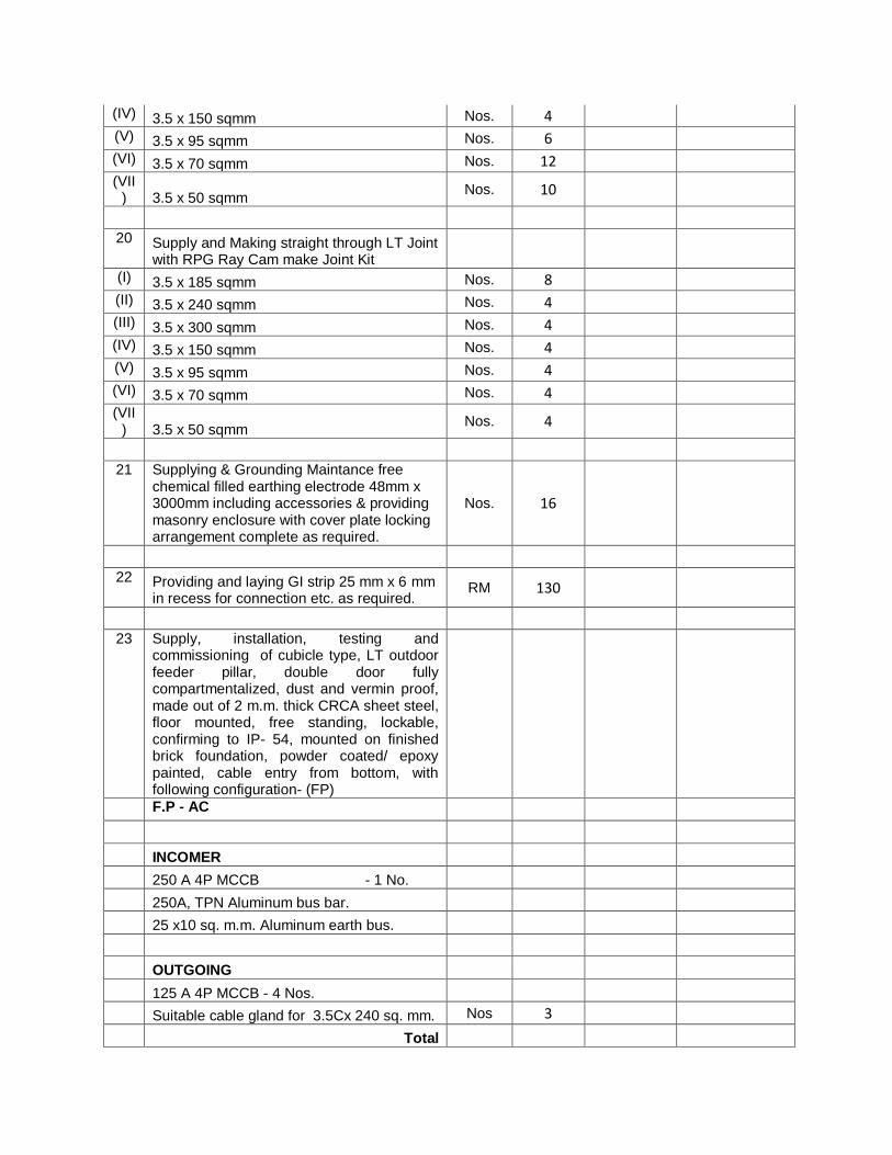
(IV) 3.5 x 150 sqmm Nos. 4 (V) 3.5 x 95 sqmm Nos. 6 (VI) 3.5 x 70 sqmm Nos. 12 (VII
) 3.5 x 50 sqmm Nos. 10
20 Supply and Making straight through LT Joint
with RPG Ray Cam make Joint Kit
(I) 3.5 x 185 sqmm Nos. 8 (II) 3.5 x 240 sqmm Nos. 4 (III) 3.5 x 300 sqmm Nos. 4 (IV) 3.5 x 150 sqmm Nos. 4 (V) 3.5 x 95 sqmm Nos. 4 (VI) 3.5 x 70 sqmm Nos. 4 (VII
) 3.5 x 50 sqmm Nos. 4
21 Supplying & Grounding Maintance free
chemical filled earthing electrode 48mm x 3000mm including accessories & providing masonry enclosure with cover plate locking arrangement complete as required.
Nos. 16
22 Providing and laying GI strip 25 mm x 6 mm
in recess for connection etc. as required. RM 130
23 Supply, installation, testing and
commissioning of cubicle type, LT outdoor feeder pillar, double door fully compartmentalized, dust and vermin proof, made out of 2 m.m. thick CRCA sheet steel, floor mounted, free standing, lockable, confirming to IP- 54, mounted on finished brick foundation, powder coated/ epoxy painted, cable entry from bottom, with following configuration- (FP)
F.P - AC INCOMER 250 A 4P MCCB - 1 No. 250A, TPN Aluminum bus bar.
25 x10 sq. m.m. Aluminum earth bus.
OUTGOING
125 A 4P MCCB - 4 Nos.
Suitable cable gland for 3.5Cx 240 sq. mm. Nos 3
Total

Net Total
Grand Total
Warranty:
Standard warranty as given by the manufacturer on the machines shall be clearly mentioned in the technical bid.
Warranty on the installation and other accessories including electric panel shall be of minimum of 01 year.


![StructuredGround Grounding Auxiliary Cable Brackets and ... · Grounding Busbar] (SBB/TGB) or other suitable grounding infrastructure. Cable pathway sections shall be bonded together](https://static.fdocuments.us/doc/165x107/5eb5dc8594c7ea1dad77aeb8/structuredground-grounding-auxiliary-cable-brackets-and-grounding-busbar-sbbtgb.jpg)


