
The Linac Modulator - Advanced Photon Source · 2. The Linac Modulator. Introduction. Klystron. The...
19
1 The Linac Modulator 1. Introduction 2. Block Diagram 3. Charging PFN Capacitors 4. Dumping the PFN 5. Monitoring PFN Voltage 6. The Summing Box 7. Pulsing 8. Forming the Pulse 9. PFN Impedance 10. Secondary Pulse Shape 11. End of Line Clipper 12. Auxiliary Power Supplies 13. Modulator Control
Transcript of The Linac Modulator - Advanced Photon Source · 2. The Linac Modulator. Introduction. Klystron. The...

1
The Linac Modulator
1.
Introduction
2.
Block Diagram
3.
Charging PFN Capacitors
4.
Dumping the PFN
5.
Monitoring PFN Voltage
6.
The Summing Box
7.
Pulsing
8.
Forming the Pulse
9.
PFN Impedance
10.
Secondary Pulse Shape
11.
End of Line Clipper
12.
Auxiliary Power Supplies
13.
Modulator Control
2
The Linac Modulator. Introduction
Klystron
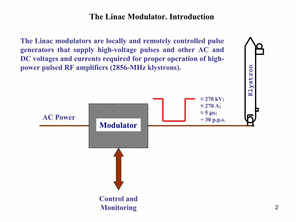
The Linac modulators are locally and remotely controlled pulse generators that supply high-voltage pulses and other AC and DC voltages and currents required for proper operation of high-
power pulsed RF amplifiers (2856-MHz klystrons).
≈
270 kV; ≈
270 A; ≈
5 μs; = 30 p.p.s.AC Power
Control and Monitoring
Modulator
3
The Linac Modulator. Block Diagram
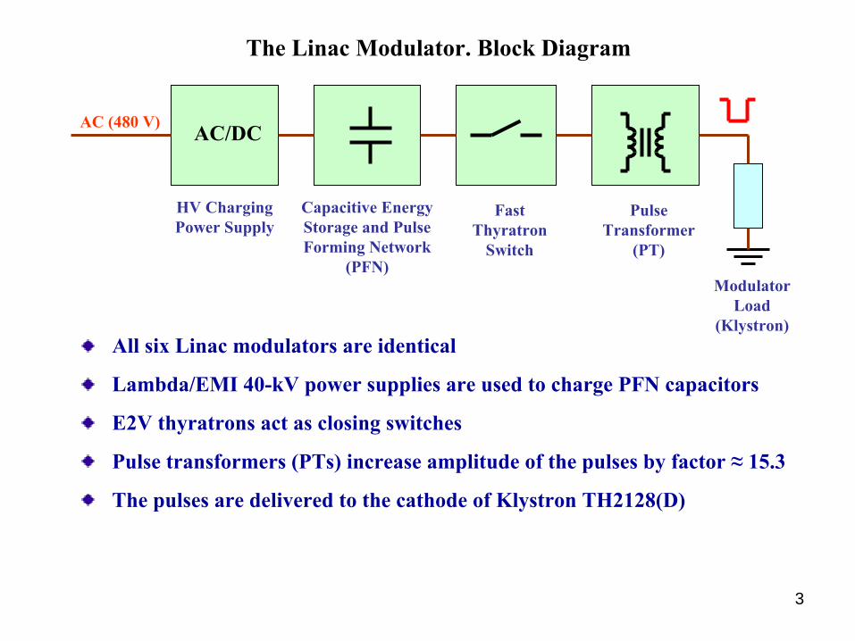
All six Linac modulators are identical
Lambda/EMI 40-kV power supplies are used to charge PFN capacitors
E2V thyratrons act as closing switches
Pulse transformers (PTs) increase amplitude of the pulses by factor ≈
15.3
The pulses are delivered to the cathode of Klystron TH2128(D)
AC/DC
HV Charging Power Supply
Capacitive Energy Storage and Pulse Forming Network
(PFN)
Fast Thyratron
Switch
Pulse Transformer
(PT)
Modulator Load
(Klystron)
AC (480 V)
4
The Linac Modulator. Charging PFN Capacitors
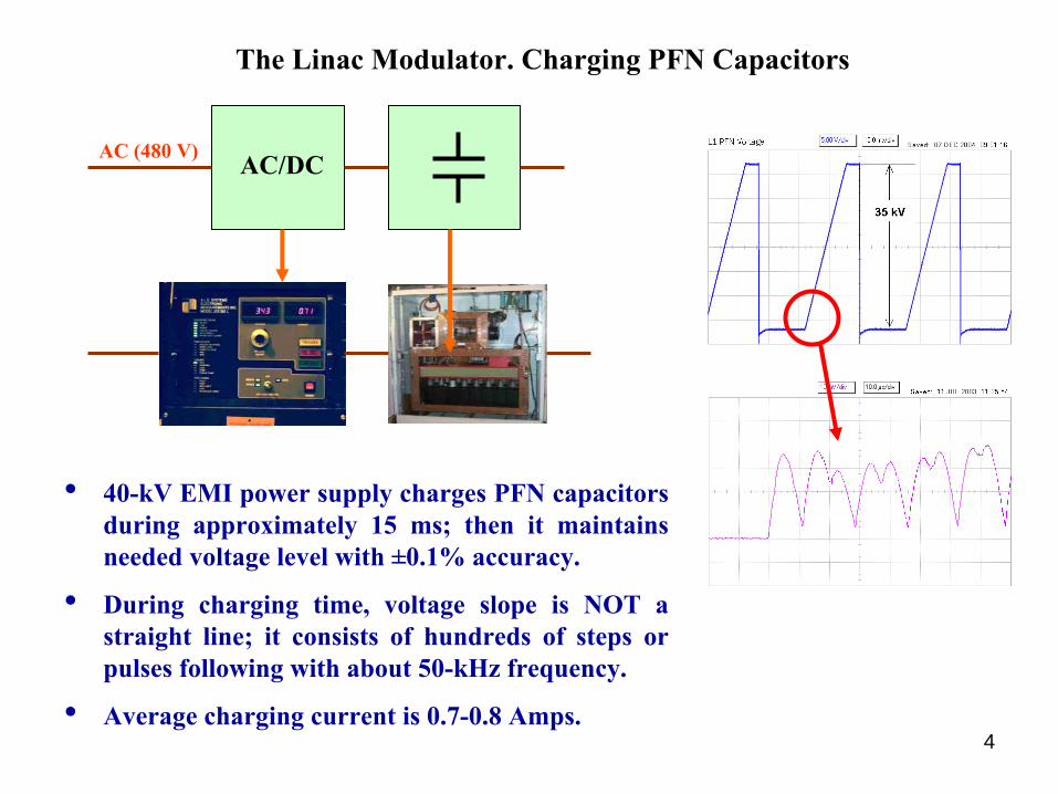
AC/DCAC (480 V)
• 40-kV EMI power supply charges PFN capacitors during approximately 15 ms; then it maintains needed voltage level with ±0.1% accuracy.
• During charging time, voltage slope is NOT a straight line; it consists of hundreds of steps or pulses following with about 50-kHz frequency.
• Average charging current is 0.7-0.8 Amps.
10/21/2008 Alex Cours 5
The Linac Modulator. Dumping the PFN
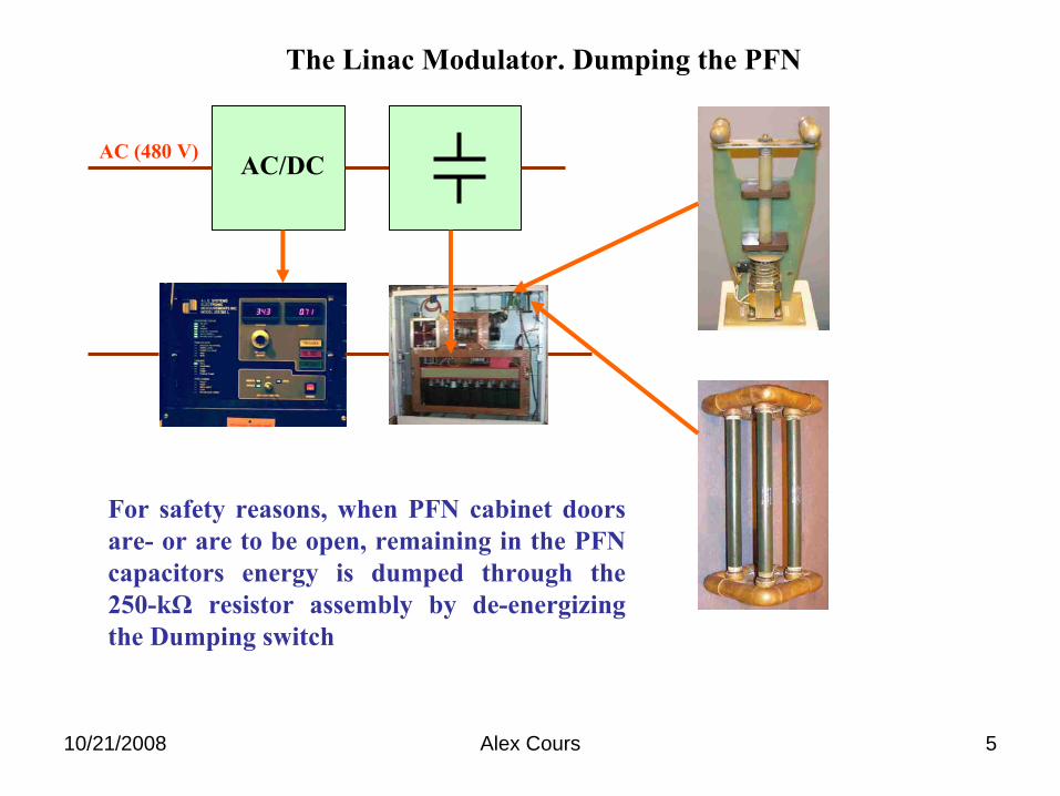
AC/DCAC (480 V)
For safety reasons, when PFN cabinet doors are-
or are to be open, remaining in the PFN capacitors energy is dumped through the 250-kΩ
resistor assembly by de-energizing the Dumping switch

6
The Linac Modulator. Monitoring PFN Voltage
AC/DCAC (480 V)
PFN Voltage is monitored by means of two Ross Voltage dividers (VD) filled with SF6 isolating gas. Signal from one VD is sent to the modulator control system and used for read back purposes
The second VD is used only for local monitoring through the BNC connector located on the side wall of the PFN cabinet.

7
The Linac Modulator. Summing Box (SB)
AC (480 V)SB
• The Summing Box (SB) consists of a HV diode assembly and four resistors connected in parallel with total resistance of 50 Ω
• The SB protects EMI HV power supply against possible PFN voltage reversals, spikes, etc.
AC/DC
8
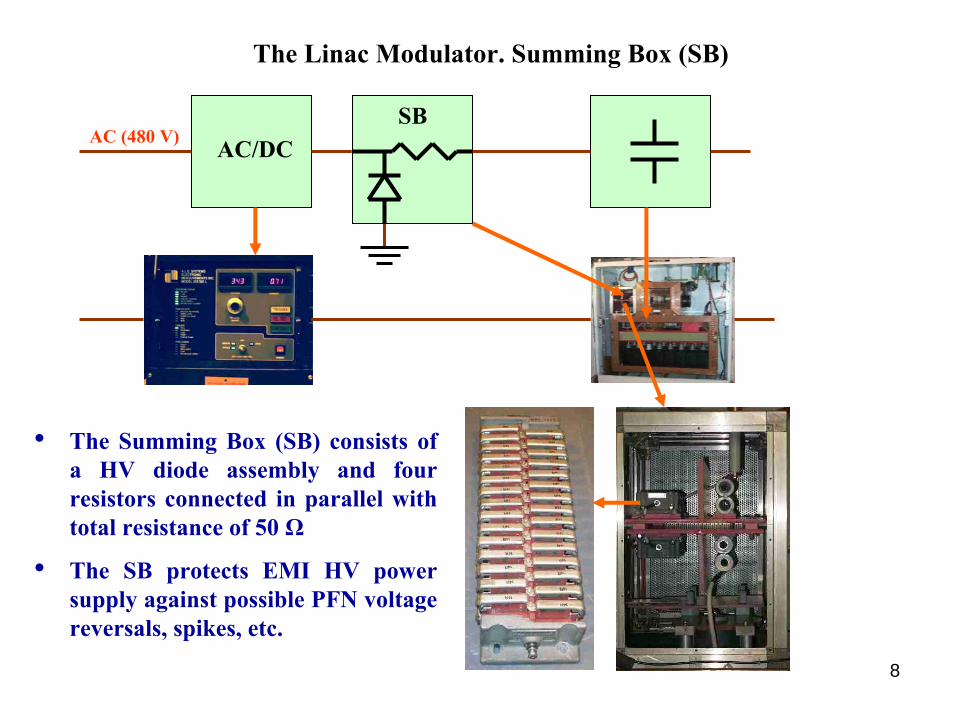
The Linac Modulator. Summing Box (SB)
AC/DCAC (480 V)SB
• The Summing Box (SB) consists of a HV diode assembly and four resistors connected in parallel with total resistance of 50 Ω
• The SB protects EMI HV power supply against possible PFN voltage reversals, spikes, etc.
9
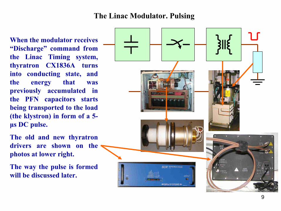
The Linac Modulator. Pulsing
When the modulator receives “Discharge”
command from the Linac Timing system, thyratron CX1836A turns into conducting state, and the energy that was
previously accumulated in the PFN capacitors starts being transported to the load (the klystron) in form of a 5-
μs DC pulse.
The old and new thyratron drivers are shown on the photos at lower right.
The way the pulse is formed will be discussed later.
10
C R
SW
1 101
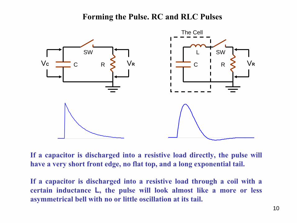
Forming the Pulse. RC and RLC Pulses
VR C R
SWL
The Cell
VRVC
If a capacitor is discharged into a resistive load directly, the
pulse will have a very short front edge, no flat top, and a long exponential tail.
1 101
If a capacitor is discharged into a resistive load through a coil with a certain inductance
L, the pulse will look almost like a more or less asymmetrical bell with no or little oscillation at its tail.

11
1
N = 1
1
N = 1 2
1
N = 1 2 4
1
N = 1 2 4 8
R
SW
C
L
Cell 1
C
L
C
L
C
L
From a Single Cell to the Pulse Forming Network (PFN)
C
L
Cell 8
Initial overshooting and oscillation are inherent in this type of PFN.
They may be more or less successfully compensated by adjusting capacitance and/or inductance of certain cells.
As the number of identical cells in the PFN grows, the pulse becomes wider and more square.
12
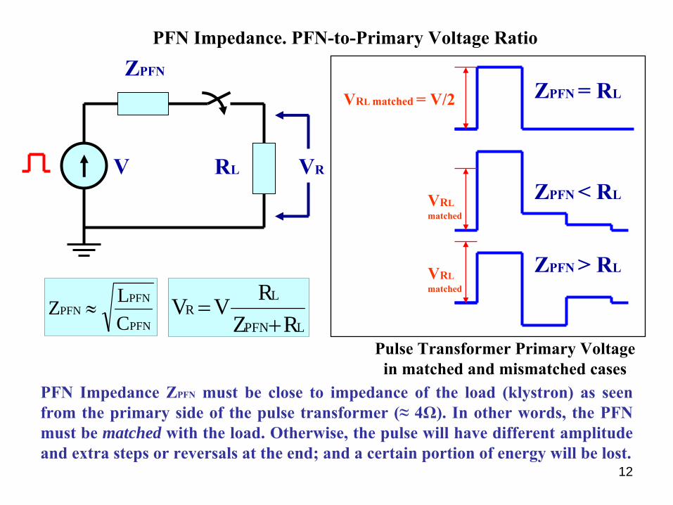
PFN Impedance. PFN-to-Primary Voltage Ratio
V
ZPFN
RL VR
LPFN
LR
RZRVV+
=PFN
PFNPFN
CLZ ≈
PFN Impedance ZPFN
must be close to impedance of the load (klystron) as seen from the primary side of the pulse transformer (≈
4Ω). In other words, the PFN must be matched with the load. Otherwise, the pulse will have different amplitude and extra steps or reversals at the end; and a certain portion of energy will be lost.
ZPFN = RLVRL matched = V/2
ZPFN < RLVRL
matched
ZPFN > RLVRL
matched
Pulse Transformer Primary Voltage in matched and mismatched cases
13
0 1200 120
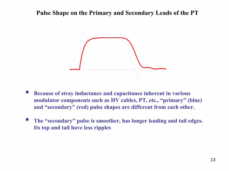
Pulse Shape on the Primary and Secondary Leads of the PT
Because of stray inductance and capacitance inherent in various modulator components such as HV cables, PT, etc., “primary” (blue) and “secondary” (red) pulse shapes are different from each other.
The “secondary” pulse is smoother, has longer leading and tail edges. Its top and tail have less ripples
14
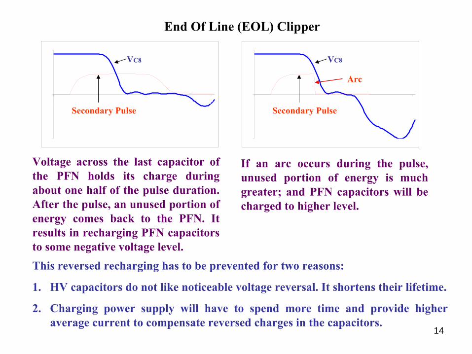
End Of Line (EOL) Clipper
Voltage across the last capacitor of the PFN holds its charge during about one half of the pulse duration. After the pulse, an unused portion of energy comes back to the PFN. It results in recharging PFN capacitors to some negative voltage level.
-1
0
1
1 111
Secondary Pulse
VC8
-1
0
1
1 111
Secondary Pulse
VC8
Arc
If an arc occurs during the pulse, unused portion of energy is much
greater; and PFN capacitors will be charged to higher level.
This reversed recharging has to be prevented for two reasons:
1.
HV capacitors do not like noticeable voltage reversal. It shortens their lifetime.
2.
Charging power supply will have to spend more time and provide higher average current to compensate reversed charges in the capacitors.
15
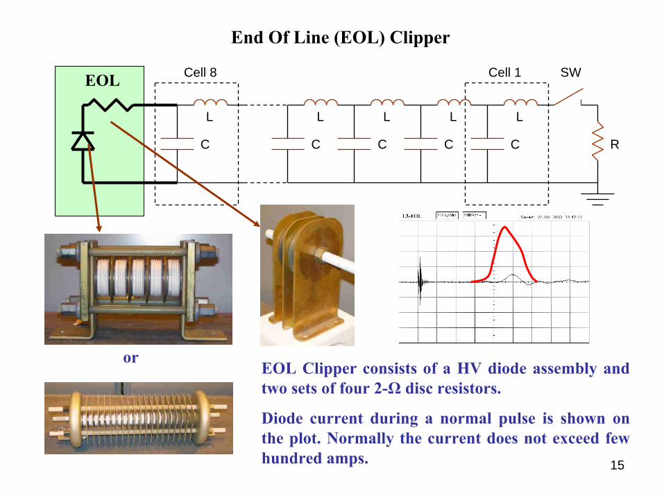
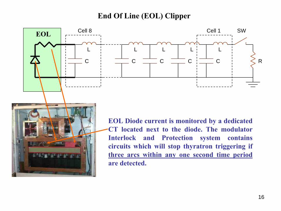
End Of Line (EOL) Clipper
EOL Clipper consists of a HV diode assembly and two sets of four 2-Ω
disc resistors.
Diode current during a normal pulse is shown on the plot. Normally the current does not exceed few hundred amps.
R
SW
C
L
Cell 1
C
L
C
L
C
L
C
L
Cell 8EOL
or
16
End Of Line (EOL) Clipper
EOL Diode current is monitored by a dedicated CT located next to the diode. The modulator Interlock and Protection system contains circuits which will stop thyratron triggering if three arcs within any one second time period
are detected.
R
SW
C
L
Cell 1
C
L
C
L
C
L
C
L
Cell 8EOL
17
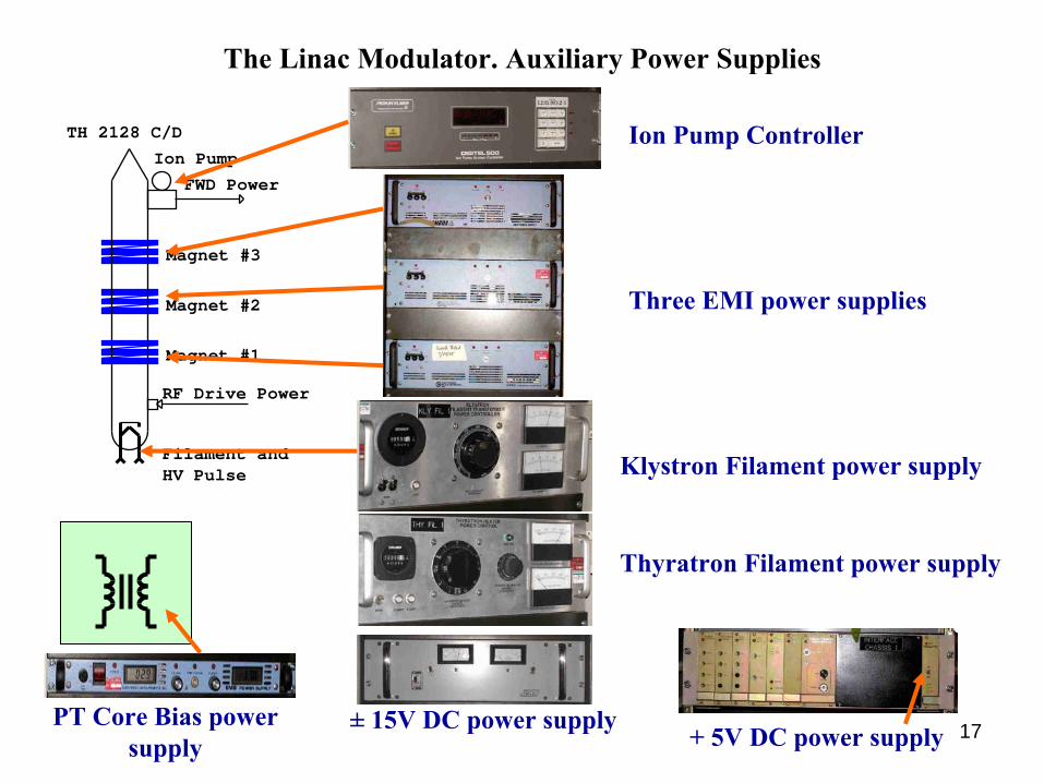
The Linac Modulator. Auxiliary Power Supplies
FWD Power
Ion Pump
Magnet #2
TH 2128 C/D
RF Drive Power
Magnet #1
Magnet #3
Filament andHV Pulse
Ion Pump Controller
Three EMI power supplies
Klystron Filament power supply
±
15V DC
power supply+ 5V DC
power supplyPT Core Bias
power supply
Thyratron Filament power supply

18
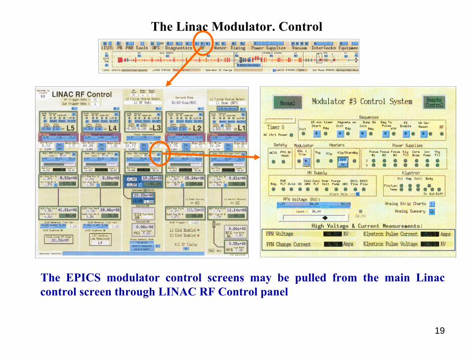
The Linac Modulator. Control
• The modulators have Local and Remote control modes
• Local control and communication with EPICS is performed by the Allen-Bradley controller
• All input and output signals are filtered in the SFC chassis
• The touch-screen monitor makes it easy to operate the modulator, to change settings, voltage and current limits, etc.
19
The Linac Modulator. Control
The EPICS modulator control screens may be pulled from the main Linac control screen through LINAC RF Control panel