![Artificial Photosynthesis: Beyond Mimicking Nature · 2017. 12. 4. · Artificial Photosynthesis: Beyond Mimicking Nature. Holger Dau,* [a] Etsuko Fujita,* [b] and Licheng Sun* [c,](https://static.fdocuments.us/doc/165x107/60fe452775a71d1de4329da9/artificial-photosynthesis-beyond-mimicking-nature-2017-12-4-artificial-photosynthesis.jpg)
The latest state-of-the-art on artificial photosynthesis latest state-of-the-art on artificial...
18
The latest state-of-the-art on artificial photosynthesis Ibram Ganesh Centre for Photoelectrochemical Cells, International Advanced Research Centre for Powder Metallurgy and New Materials (ARCI), Hyderabad - 500 005, A.P., (INDIA) E-mail: [email protected] Abstract : Conversion of carbon dioxide into value added chemical fuels (methanol and ethanol) using re- newable energy (sunlight or electricity derived from sun- light) is of great importance from the point of view of addressing the CO 2 associated global warming, energy crisis (depletion of fossil fuels) and energy storing prob- lems to a great extent. This is process is popularly known as artificial photosynthesis. The importance of electro- chemical reduction of CO 2 and the underlying reaction mechanisms, and the latest developments in electro- chemical CO 2 reduction process, and the CO 2 specia- tion are presented and summarized in this article. Fur- ther, this manuscript discusses how the electrochemical reduction process is superior over stoichiometric, ther- mochemical, photoelectrochemical and photocatalytic processes as far as artificial photosynthesis is concerned. Global Scientific Inc. Keywords : Carbon dioxide; Speciation; Electro- chemical cells; Artificial photosynthesis; Global warm- ing; Energy crisis. THE PRIOR ART Recently, the conversion of carbon dioxide into value added chemicals using exclusively solar energy, which is popularly known as artificial photosynthesis, has received a great deal of attention from the scientific community as it deals with the CO 2 associated global warming prob- lem [1-3] energy crisis (i.e., depletion of fossil fuels) [4-6] , and storing energy (electricity or sunlight) in a most de- sirable form of liquid fuels with sufficiently high energy density [7] . Recently, the Intergovernmental Panel on Cli- mate Change (IPCC) has concluded that the fossil fuel burning and deforestation are responsible for increased CO 2 concentrations in atmosphere. The atmospheric anthropogenic CO 2 concentrations have risen by ~30% from pre-industrial (prior to 1750) levels of 280 ppm to 400 ppm today. The present CO 2 levels in atmosphere are higher than at any time during the last 650000 years for which the reliable data was extracted from ice cores [1- 3,8,9] . The CO 2 associated greenhouse effect was first noted by Joseph Fourier in 1824 and was further sub- stantiated quantitatively later on by Svante Arrhenius in 1896. The greenhouse gases warm the planet s atmo- sphere and surface by absorption and reemission of the infrared radiation of solar light. The civilization and in- dustrialization have not only brought technology, modern life, and convenience to the human beings but also pollu- tion and emissions from factories, vehicles, and chemical plants. Several national governments have signed and ratified the Kyoto Protocol of the United Nations Frame- work Convention on Climate Change aiming at reducing CO 2 gas emissions [1-3] . Recently, the International En- ergy Agency (IEA)-World Energy Outlook (WEO) re- vealed that, based on policies being practiced at the Review ISSN(Print) : 2320 1967 ISSN(Online) : 2320 1975 ChemXpress 3(4), 131-148, (2014)
Transcript of The latest state-of-the-art on artificial photosynthesis latest state-of-the-art on artificial...

The latest state-of-the-art on artificial photosynthesis
Ibram Ganesh
Centre for Photoelectrochemical Cells, International Advanced Research Centre for PowderMetallurgy and New Materials (ARCI), Hyderabad - 500 005, A.P., (INDIA)
E-mail: [email protected]
Abstract : Conversion of carbon dioxide into valueadded chemical fuels (methanol and ethanol) using re-newable energy (sunlight or electricity derived from sun-light) is of great importance from the point of view ofaddressing the CO
2 associated global warming, energy
crisis (depletion of fossil fuels) and energy storing prob-lems to a great extent. This is process is popularly knownas artificial photosynthesis. The importance of electro-chemical reduction of CO
2 and the underlying reaction
mechanisms, and the latest developments in electro-chemical CO
2 reduction process, and the CO
2 specia-
tion are presented and summarized in this article. Fur-ther, this manuscript discusses how the electrochemicalreduction process is superior over stoichiometric, ther-mochemical, photoelectrochemical and photocatalyticprocesses as far as artificial photosynthesis is concerned.Global Scientific Inc.
Keywords : Carbon dioxide; Speciation; Electro-chemical cells; Artificial photosynthesis; Global warm-ing; Energy crisis.
THE PRIOR ART
Recently, the conversion of carbon dioxide into valueadded chemicals using exclusively solar energy, which ispopularly known as artificial photosynthesis, has receiveda great deal of attention from the scientific community asit deals with the CO
2 associated global warming prob-
lem[1-3] energy crisis (i.e., depletion of fossil fuels)[4-6],and storing energy (electricity or sunlight) in a most de-sirable form of liquid fuels with sufficiently high energydensity[7]. Recently, the Intergovernmental Panel on Cli-mate Change (IPCC) has concluded that the fossil fuelburning and deforestation are responsible for increasedCO
2 concentrations in atmosphere. The atmospheric
anthropogenic CO2 concentrations have risen by ~30%
from pre-industrial (prior to 1750) levels of 280 ppm to400 ppm today. The present CO
2 levels in atmosphere
are higher than at any time during the last 650000 yearsfor which the reliable data was extracted from ice cores[1-
3,8,9]. The CO2 associated greenhouse effect was first
noted by Joseph Fourier in 1824 and was further sub-stantiated quantitatively later on by Svante Arrhenius in1896. The greenhouse gases warm the planet�s atmo-
sphere and surface by absorption and reemission of theinfrared radiation of solar light. The civilization and in-dustrialization have not only brought technology, modernlife, and convenience to the human beings but also pollu-tion and emissions from factories, vehicles, and chemicalplants. Several national governments have signed andratified the Kyoto Protocol of the United Nations Frame-work Convention on Climate Change aiming at reducingCO
2 gas emissions[1-3]. Recently, the International En-
ergy Agency (IEA)-World Energy Outlook (WEO) re-vealed that, based on policies being practiced at the
Review
ISSN(Print) : 2320 �1967ISSN(Online) : 2320 �1975
ChemXpress 3(4), 131-148, (2014)
id272578 pdfMachine by Broadgun Software - a great PDF writer! - a great PDF creator! - http://www.pdfmachine.com http://www.broadgun.com
.132
ReviewChemXpress 3(4), 2014
moment, by 2030 CO2 emissions will attain 63% from
today�s level, which is almost 90% higher than those of
1990[10]. Hence, to avoid further increase over the nextfew decades, improved actions than those of currentlypracticed should be taken, which include the develop-ment and employment of technologies to cut down CO
2
emissions[10]. One of such options is to capture the CO2
generated at major outlets (mainly at thermal powerplants), where each tonne of coal is burned to releaseabout 4 tonnes of CO
2, and prevent it from entering into
atmosphere by suitably capturing it and then storing insafe places. Further, this captured CO
2 can also be con-
verted into several value added and fuel chemicals[4]. Atpresent, the readily available technology to tackle withCO
2 associated global warming problem is CO
2 seques-
tration process[10]. This process also called as carboncapture and storage (CCS). On the other hand, the car-bon capture and utilization (CCU) process has been con-sidered to be an economically valuable option in com-parison to CCS process. Besides economic benefits, thesocio-political benefits also come in terms of a positiveimage for companies adopting policies of utilizing CO
2
formed from fossil fuels[3,7,11].The use of CO
2 as a building block for the synthesis
of chemicals can in fact contribute to a sustainable chemi-cal industry, and as a consequent reduce CO
2 emissions
into the atmosphere[11]. Further, CO2 can also be used
as a fluid in several applications. At present, all over theworld, there are increased research efforts to developeffective methods that utilize CO
2 as a feed stock[3,7,11].
Many industrial methods have been developed to havean encouraging influence on atmospheric CO
2 so that
the captured CO2 is need not have to be buried or vent
into an open atmosphere. Bulk chemicals at presentbeing produced from CO
2 are urea, salicylic acid, and
polycarbonate-based plastics[4,11]. CO2 is also a sol-
vent, for example, supercritical CO2 (the state existing
at 31°C and 72.8 bars pressure) tender several advan-tages in terms of stereo-chemical control, product puri-fication, and environmental issues for synthesizing cer-tain fine chemicals and pharmaceutical compounds. Otheropportunities for using CO
2 include enhanced oil and
gas recovery, enhanced agricultural production, andponds of genetically modified algae so that biodiesel canbe produced from power-plant CO
2[11]. All these meth-
ods can reduce CO2 emissions by at least 3.7 gigatons
per year (approximately 10% of total present annualCO
2 emissions), which, in fact, can reduce the use of
fossil fuels. Further reductions in CO2 emissions could
be possible if these technologies are expanded far widely.Since, total anthropogenic CO
2 emission is ~25 gigatons
per year, the CCS process is definitely a major readilyavailable solution to mitigate CO
2 related global warm-
ing problem at the moment[10].On the other hand, today, the majority of the world�s
primary energy requirement is met from fossil fuels. Powerplants use fossil fuels (coal, oil or natural gas) to produceelectrical energy. As per today�s consumption rate, the
available coal reserves will last for another 130 years,natural gas for 60 years, and oil for 42 years[3,7]. As shownin Figure 1, Hubbert�s curve shows that in next 40 years
the recoverable oil becomes significantly low and sug-gests finding an alternative energy economy in the next20-year timeframe on an urgent basis[12]. It is importantto realize the reliable alternative energy resources, be-fore the oil resources are completely exhausted. Oil andnatural gas are the starting materials for several impor-tant chemicals that are today used in every day-to-daylife of the society. Hence, we cannot afford to use suchimportant limited oil, natural gas and coal resources onlyto meet just energy needs instead of several other impor-tant chemical needs of the future human generations. Fur-ther, these resources are not only to use for just few de-cades of the future but for the continued industrial appli-cations of next several centuries. In addition to these, thecurrent fossil fuel consumption rate, their particular geo-graphic distribution, and the political control over thempose problems for the nations which are fully dependanton fossil fuels. The rapidly growing population and in-dustrialization are also further demanding the increasedenergy requirement day-after-day[3,7].
Out of today�s total energy consumption, about
43% is provided by oil and derived liquid fuels whichinclude gasoline, diesel, jet fuels, gasoil, etc.[3,7]. Onlyabout 17% energy requirement is met by the electric-ity. It is hard to depend only on electricity as the ac-tual energy density of electricity storing batteries istoo low for many energy-intensive applications as theircapacity for storing energy per kilogram of weight orfor the unit volume is only about 1% in comparison togasoline�s energy density (Figure 2)[3,7]. Even if there

133
ReviewChemXpress 3(4), 2014
Figure 1 : This graph shows the classic Hubbert curve, indicating that world oil resources are on track to critically depletewithin 40 years. While this figure is hotly debated, what is clear is that oil has a host of useful industrial applications and toirreversibly burn oil jeopardizes the future. The vertical scale is in arbitrary relative units, but to get an idea of scale, worldproduction averaged at about 80 million barrels per day in 2008 (adapted from[12]).
Figure 2 : Energy density per weight vs. per volume in a series of liquid and gaseous fuels (from fossil sources, or renewablesuch as ethanol and DMF), H
2 (liquid, gas, compressed at 700 bar, and stored in advanced nano-material) and electrical energy
(Li ion batteries, conventional and advanced). NG: natural gas; DMF: dimethyl furan; LPG: liquefied petroleum gas (adaptedfrom[7]).
is a breakthrough in the research of energy storage inbatteries, these batteries cannot meet the requirementof many of the existing applications. Further, batteriesalso have certain limitations with respect to their cost,lifetime, time of recharge, etc.. It has been estimatedthat even if all the vehicles run with electricity in thefuture, the demand for electricity would increase byonly <1% extra[3,7]. Besides this, at the moment, bat-
teries cannot be used to run certain heavy vehiclessuch as, planes, buses, trucks, etc., as they need anon-board energy feeding with high energy density andeasy to fill fuels (liquids)[3,7]. Liquid fuels possess about100 times higher energy density (~50 MJ kg1) in com-parison to many of the available energy storage meth-ods (Figure 2). Hence, carbon-neutral, sustainable andeasy to scale-up fuel storage methods are required to

.134
ReviewChemXpress 3(4), 2014
be developed as alternatives to the fossil fuels.
ENERGY DENSITY COMPARISON OFVARIOUS FUEL CHEMICALS
The important resources of renewable energy arebiomass, solar, wind, tides and hydro-based systems.Except, biomass all others produce electricity. The pro-duction of liquid fuels from biomass has been identifiedto be quite laborious, and probably much research is stillneeded to find out a more economic and easier way[3,7].The both nuclear and biomass (non-fossil energy alter-natives) cannot supply the today�s total energy demand
that is met from fossil fuels. Furthermore, other than liq-uid fuels, even if any fuel is produced from renewableenergy resources like sunlight, that will disturb the presentenergy supply infrastructure leading to substantial conse-quences to the global economy. In the recent past, it wasthought that H
2 could replace the fossil fuels, but it could
not do so. At this moment, the main source of the most ofcommercial H
2 is still fossil fuels (mainly natural gas) and
for generating a unit of heat from H2, more CO
2 is gener-
ated than directly burning those fossil fuels. At present,H
2 produced following electrolysis methods is expansive
and it cannot be compared with the cost of H2 produced
from fossil fuels. As on today, the self-sufficiency in en-ergy is each and every country�s primary objective. In
fact, most of the following strategies for achieving thisgoal are either environmentally unacceptable and are notfeasible except those depend on fossil fuel based resourcessuch as natural gas[3,7]. As the conventional nuclear powerplants need uranium, which is limited and has always as-sociated with the problems of radiation leakage due tonatural calamities, etc., the solar energy is considered tobe the only potent non-fossil fuel renewable energy re-source. It is estimated that in a two weeks� time, the
surface of the earth receives the energy that is equal tothe total energy that is present in the entire world�s fossil
fuel resources (1016 kW)[13]. The mean solar irradianceat normal incidence outside the atmosphere is 1360 W/m2 and the total annual incidence of solar energy in Indiaalone is about 107 kW and for the southern region, thedaily average is about 0.4 kW/m2. In every hour, theearth receives solar energy that is equal to the entire worldpeople�s energy requirement in a year. Further, solar en-
ergy is clean, non-polluting, inexhaustible and carbon-
free, hence no question of climatic problems such as glo-bal warming[13].
In year 2004, the world�s energy requirement was
about 18 TW and it is expected to reach 28 TW in theyear 2030. One of the energy agencies predicted that ifthe solar irradiance of 1% of the Earth�s surface is con-
verted into storable energy with 10% efficiency, it wouldprovide a resource base of 105 TW that is equal to theseveral times of the estimated world energy requirementin the year 2050[7]. Whereas, the amount of energy thatcould be extracted in the same year 2050 from wind,tides, biomass, and geothermal would be only 2�4 TW,
2�3 TW, 5�7 TW, and 3�6 TW, respectively. Further-
more, energy needs to be supplied continuously day andnight without any interruption. Even though, solar lightenergy is enough; it is not available in the nights and oncloudy days. Hence, to supply solar energy continuouslyto the society, a proper method is required to store it in asuitable form[7]. However, the most of the solar energystorage methods developed so far are associated withlow energy densities. The energy density by mass of com-pressed air (300 atm.), batteries, flywheels, super-ca-pacitors, H
2O pumped 100 meters uphill are estimated
to be ~0.5 MJ kg1, ~0.1�0.5 MJ kg1, ~0.5 MJ kg1,~0.01 MJ kg1, and ~0.001 MJ kg1, respectively[7].Although several technologies including photovoltaic cells,Peltier (or Seebeck) modules, Fresnel lenses, concen-trated solar radiation, solar thermal energy, etc., havealready been developed for converting sunlight into elec-tricity, there is a discontinuity between solar irradiationand power consumption during the year and in terms ofgeographical distribution[7]. The same is true even for windand tide based energy resources. Therefore, it is requiredto realize a suitable method to store and transport thesolar energy in the suitable chemical form. Using tech-nologies available today, solar energy can be stored inthe form of hydrogen by splitting water into hydrogenand oxygen using electricity that is produced from solarenergy (eq. 1)[7]. Although, methods like bio-routes (thatuse cyano-bacteria or green algae), high temperature ther-mochemical routes (that use concentrated solar radia-tion), photoelectrochemical water splitting or photo-elec-trolysis routes, etc., produce H
2 at atmospheric pres-
sure, eventually this H2 needs to be compressed in a pres-
sure cylinder for using it in any of its intended applica-tions.

135
ReviewChemXpress 3(4), 2014
2H2O + h (light) + semiconductor 2H
2 + O
2(1)
Recently, several advantages and disadvantages as-sociated with various hydrogen production routes havebeen reviewed in the literature[14]. It has been estimatedthat about 40% of the produced H
2 value is required to
spend to compress it into a pressure cylinder beforeuse it in any of its applications[14]. Among various meth-ods developed so far for producing H
2 gas from water,
the photovoltaics based technology has been identifiedto be the best. Figure 2 illustrates the energy densitiesof various materials such as, liquid fuels (from fossil orrenewable sources), H
2 (gas, liquid, compressed or in
storage materials), electrical energy (in conventional ornew generation Li-batteries), etc.[7]. In fact, the practi-cal applications require high energy densities per weightand per volume. In the case of light weight H
2 gas, en-
ergy density per volume is the main criterion. It can alsobe clearly seen from Figure 2 that the energy densitiesof H
2 and electrical storage are far low in compared to
those of liquid fuels based on fossil or renewable (bio-mass) sources. Furthermore, H
2 gas usage requires large
costs for a new energy infrastructure as it cannot bedirectly employed in the present existing energy infra-structure including the automobile vehicles, thus not al-lowing a smooth transition from fossil fuel based energyvectors to the renewable and/or solar energy basedenergy vectors. This demands that the production offuels in the liquid form (even if it is carbon-based) ispreferred, because it can be employed directly in placeof fossil fuels, which are presently being used to meetthe energy requirements of the society beings[7]. Fur-ther, liquid fuels can be preserved for the future needstoo with suitable additives[3,7].
The challenges for converting CO2 into value added
chemicals including methanol are great, but the potentialrewards are also enormous. The conversion of CO
2 into
methanol using energy that has not come from fossil fuelshas been suggested to be one of the best ways to storethe energy and solve both global warming and energycrisis problems to a considerable extent[7]. Furthermore,methanol could be employed smoothly into the existingenergy distribution infrastructure today without makingany major changes to it. The additional advantages inproducing methanol from CO
2 include i) high energy den-
sity by volume and by weight; ii) no need high pressureto store methanol at room temperature like H
2, iii) safe to
handle, and shows limited risks in its distribution (non-technical) use; iv) no need to modify the internal com-bustion engines of the vehicles to use methanol; and v)no impact on the environment during production and us-age, and methanol could be a primary feedstock for manyof the organic compounds, and is a vital intermediate forseveral bulk chemicals used in humans life such as sili-cone, paint, and plastics[5,11]. Furthermore, methanol is agreen fuel and has almost half of the energy density incomparison to mostly used fuel gasoline.
At present, the most of the commercial methanol isproduced from synthetic gas (also called as syngas(CO+H
2)) on a quite large scale in industrial plants in a
several millions tons per year capacity. Besides this, theprocesses like, selective oxidation of methane, catalyticgas phase oxidation of methane, liquid phase oxidationof methane, mono-halogenation of methane, microbialand photochemical conversion of methane, etc., are alsobeing employed to produce methanol[5,11]. Nevertheless,production of methanol from CO
2 using solar energy to
drive the reaction is highly attractive as it saves the natu-ral fossil fuel resources. Nature converts CO
2 into
bioenergy via natural photosynthesis using exclusivelysolar energy. In this process, somewhat less than 1% ofthe solar energy is converted into bioenergy in the formof plant materials, which when accumulated and trans-formed over geologic ages yielded fossil fuels[15]. Thus,artificial photosynthesis has a tremendous potential and itis a scientific challenge, and upon successful develop-ment of it, the market would be gigantic. Owing to CO
2�s
extremely stable chemical nature, converting it back to auseful value added chemical, which is an endothermicreaction, on the same scale and with the same rate cur-rently that is being produced is out of today�s scientific
and technological ability. However, a close study of theexisting information on this subject hints that the success-ful development of artificial photosynthesis (i.e., conver-sion of CO
2 into value added chemicals used only re-
newable energy) is no longer an unrealistic dream[11,16-
18]. Furthermore, this process could be developed quiteefficiently in comparison to the natural photosynthesis.For example, there are certain endothermic reactionswhich are being practiced in thermochemical routes toproduce syngas, H
2, and methanol over certain metal
oxide catalysts. A considerably great amount of effortshave already made to convert CO
2 into several industri-
.136
ReviewChemXpress 3(4), 2014
ally important chemicals following a great variety of meth-ods in which different forms of energy was utilized toperform the endothermic CO
2 reduction reactions into
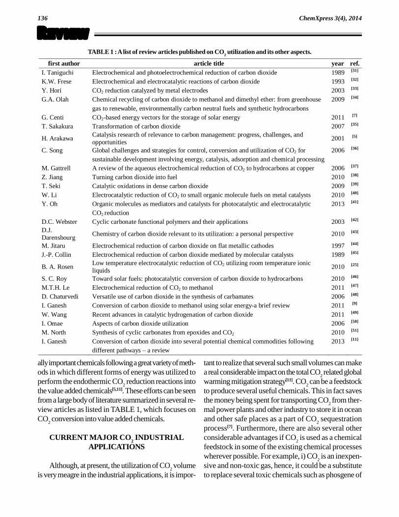
the value added chemicals[5,11]. These efforts can be seenfrom a large body of literature summarized in several re-view articles as listed in TABLE 1, which focuses onCO
2 conversion into value added chemicals.
CURRENT MAJOR CO2 INDUSTRIALAPPLICATIONS
Although, at present, the utilization of CO2 volume
is very meagre in the industrial applications, it is impor-
tant to realize that several such small volumes can makea real considerable impact on the total CO
2 related global
warming mitigation strategy[11]. CO2 can be a feedstock
to produce several useful chemicals. This in fact savesthe money being spent for transporting CO
2 from ther-
mal power plants and other industry to store it in oceanand other safe places as a part of CO
2 sequestration
process[7]. Furthermore, there are also several otherconsiderable advantages if CO
2 is used as a chemical
feedstock in some of the existing chemical processeswherever possible. For example, i) CO
2 is an inexpen-
sive and non-toxic gas, hence, it could be a substituteto replace several toxic chemicals such as phosgene of
TABLE 1 : A list of review articles published on CO2 utilization and its other aspects.
first author article title year ref. I. Taniguchi Electrochemical and photoelectrochemical reduction of carbon dioxide 1989 [31]
K.W. Frese Electrochemical and electrocatalytic reactions of carbon dioxide 1993 [32]
Y. Hori CO2 reduction catalyzed by metal electrodes 2003 [33]
G.A. Olah Chemical recycling of carbon dioxide to methanol and dimethyl ether: from greenhouse 2009 [34]
gas to renewable, environmentally carbon neutral fuels and synthetic hydrocarbons
G. Centi CO2-based energy vectors for the storage of solar energy 2011 [7]
T. Sakakura Transformation of carbon dioxide 2007 [35]
H. Arakawa Catalysis research of relevance to carbon management: progress, challenges, and opportunities
2001 [5]
C. Song Global challenges and strategies for control, conversion and utilization of CO2 for 2006 [36]
sustainable development involving energy, catalysis, adsorption and chemical processing
M. Gattrell A review of the aqueous electrochemical reduction of CO2 to hydrocarbons at copper 2006 [37]
Z. Jiang Turning carbon dioxide into fuel 2010 [38]
T. Seki Catalytic oxidations in dense carbon dioxide 2009 [39]
W. Li Electrocatalytic reduction of CO2 to small organic molecule fuels on metal catalysts 2010 [40]
Y. Oh Organic molecules as mediators and catalysts for photocatalytic and electrocatalytic 2013 [41]
CO2 reduction
D.C. Webster Cyclic carbonate functional polymers and their applications 2003 [42]
D.J. Darensbourg
Chemistry of carbon dioxide relevant to its utilization: a personal perspective 2010 [43]
M. Jitaru Electrochemical reduction of carbon dioxide on flat metallic cathodes 1997 [44]
J.-P. Collin Electrochemical reduction of carbon dioxide mediated by molecular catalysts 1989 [45]
B. A. Rosen Low temperature electrocatalytic reduction of CO2 utilizing room temperature ionic liquids
2010 [25]
S. C. Roy Toward solar fuels: photocatalytic conversion of carbon dioxide to hydrocarbons 2010 [46]
M.T.H. Le Electrochemical reduction of CO2 to methanol 2011 [47]
D. Chaturvedi Versatile use of carbon dioxide in the synthesis of carbamates 2006 [48]
I. Ganesh Conversion of carbon dioxide to methanol using solar energy-a brief review 2011 [9]
W. Wang Recent advances in catalytic hydrogenation of carbon dioxide 2011 [49]
I. Omae Aspects of carbon dioxide utilization 2006 [50]
M. North Synthesis of cyclic carbonates from epoxides and CO2 2010 [51]
I. Ganesh Conversion of carbon dioxide into several potential chemical commodities following 2013 [11]
different pathways � a review

137
ReviewChemXpress 3(4), 2014
isocyanates, ii) CO2 is a renewable feedstock unlike oil
or coal, iii) production of chemicals from CO2 can lead
to a all new industrial productivity, and iv) new routesto existing chemical intermediates and products couldbe economical than current methods[11]. Thus, the re-search on CO
2 conversion and utilization could be a
proactive approach to the sustainable industrial andenergy development[11]. Hence, transformation of CO
2
into more useful organic substances has been a promis-ing long term objective.
Usually, most of the CO2 producing plants are con-
siderably far from the sites used for CO2 sequestration
or CCS process[7]. In certain areas like Europe, trans-portation of CO
2 in pipelines to storage sites is difficult
and it will increase the cost of CCS process by at least15-20%, which is considered to be unacceptable. TheDepartment of Energy (DOE), USA estimated thattransportation of CO
2 in tankers on road is not accept-
able if distance is more than 100 km[7]. In such cases,carbon dioxide capturing and utilization (CCU) is themore beneficial option to CCS. In the total CCS pro-cess, about 35-40% is the transportation and storagecosts. It is estimated that it would be between 35 and50 �/ton for early commercial phase (after year 2020)
and between 60 and 90 �/ton during demonstration
phase, when transportation of CO2 is made by pipe-
lines for distances not over 200-300 km. If the trans-portation of CO
2 is by road (for example in certain
European countries), this cost would further increase.In such cases, CCU is much more beneficial to CCSoption. The cost of methanol in Europe is about 225-240 �/ton. This cost would further increase by about
15% (about 20-30 �/ton) if methanol is produced from
a mixture of CO2 and H
2 instead of from syngas fol-
lowing the existing industrial thermochemical routes. ForCCS process, an average cost is >20-30 �/ton. These
cost values suggest that conversion of the waste CO2
gas into methanol from a mixture of CO2 and H
2 is ben-
eficial to CCS process as the value of formed methanolwould be become a bonus in the former case. If re-newable energy (such as, solar light, wind, hydro, etc.,)is utilized for this reaction, the benefits would furtherincrease. These benefits imply that CCU could be aconsiderably better option than the CCS process beingpracticed at present[7].
If the chemical activation of the inert CO2 is achieved
with only the required thermodynamic energy input with-out much of extra kinetic energy (i.e., over-potential)requirement, there could be a boost for large scale in-dustrial applications of CO
2 as a chemical feedstock[4].
At present, the major chemicals being produced fromCO
2 are urea, salicylic acid, inorganic carbonates, eth-
ylene/propylene carbonates, and polycarbonates[11].Further, it is also used as an additive to CO in the pro-duction of methanol from syngas[3]. The production ofsodium carbonate (calcined soda) by the Solvay methodalso consumes considerable volumes of CO
2. At
present, the annual production of sodium carbonate isabout 30 million tons in entire industry. In the salicylicacid synthesis also, reasonably high amount of CO
2 is
consumed. Furthermore, CO2 is also employed in the
carboxylation of phenol under pressure (Kolbe-Schmittreaction). The co-oligomerization of unsaturated hydro-carbons and CO
2 results in the formation of various
synthetic intermediates including acids, esters, lactonesand pyrones[11]. The reaction of alkynes with CO
2 (to
form 2-pyrones catalyzed by 3d metal complexes) isone of the few examples of a homogeneous catalyticreaction, which leads to the formation of C�C bond on
CO2 insertion. The variation of alkyne substituents could
result into a wide range of 2-pyrones[11]. It is knownthat the widespread use of CO
2 as a C1 feedstock needs
a higher thermodynamic energy input (>1.5 V), hence,these processes will not be economical if fossil fuels areused as a energy aid. This indicates the need of solarenergy and judicious usage of catalysts for activatingCO
2. Microalgae use solar energy to activate CO
2[15].
In the laboratory, a great variety of catalysts and meth-ods have been employed to activate CO
2 to react with
and form several value added chemicals[15].
THERMOCHEMICAL CO2 REDUCTION
Methanol can be prepared from CO2 by catalytic
hydrogenation (eq. 2) and thus obtained methanol couldbe transformed into dimethyl ether via dehydration (eq.3). These two reactions can also be performed togetherin a single-step. In the catalytic hydrogenation of CO
2
to methanol, the first step is believed to be the reversewater-gas shift (RWGS) reaction (eq. 4). In the con-ventional process, methanol is formed from syngas (eq.5) over copper-zinc-oxide-based catalysts under ex-

.138
ReviewChemXpress 3(4), 2014
treme reaction conditions (125-525C under 2-12 MPapressure). About 40 Mtons of methanol per year is beingproduced every year following the latter route[4]. In thisprocess, about 3% CO
2 is supplied together with syngas
to enhance the reaction rate. Since, RWGS is a revers-ible reaction; a same catalyst can be employed to carryout water-gas shift (WGS) and RWGS reactions. Thebest catalyst noted for these reactions has been a multi-component Cu/ZnO/ZrO
2/Al
2O
3/SiO
2 catalyst[4]. Since,
all these reactions are same equilibrium reactions, theyoccur almost at the same temperature and on the samecatalyst.CO
2 + 3H
2 CH
3OH + H
2O (2)
2CH3OH CH
3OCH
3 + H
2O (3)
CO+3H2+H
2O CO
2 + 4H
2 (water gas shift reaction) (4)
(2n + 1)H2 + nCO CnH
2n+2
(e.g., CH4, CH
3OH) + nH
2O (5)
When methanol was synthesized from CO2/H
2 mix-
ture (eq. 2) instead of from syngas (eq. 5), the notedproductivity was about 3 to 10 times lower. The waterformed in this reaction as a side-product was found toinhibit the reaction rate. It has been suggested that ifwater formed during this reaction is continuously re-moved by catalytic distillation or by the use of inorganicH
2O permselective membranes, the yield is expected
to increase[11]. The possible membranes for this pro-cess could be hydrophilic nano-pore zeolite (NaA) filmdeposited on a ceramic tubular support. This membraneis used at present for pervaporation of water-ethanolsolutions. Apart from low yields, in direct methanol syn-thesis process from CO
2, almost one third of H
2 is con-
sumed in the formation of water as a side-product.Hence, synthesis of methanol from syngas is really prof-itable. Nevertheless, considerable research efforts arestill being made with a main aim of developing highlyefficient catalysts for direct methanol synthesis from CO
2
for industrial applications[11]. For this reaction, Cu hasbeen found to be most active so far. In a study, theeffect of metal oxide support on 5 wt.% Cu catalystwas investigated and developed several kinds of excel-lent Cu-ZnO based catalysts that include Cu-ZnO-Al
2O
3-Cr
2O
3, Cu-ZnO-TiO
2, Cu-ZnO-Ga
2O
3 and Cu-
ZnO-ZrO2-Al
2O
3-Ga
2O
3[4]. Surprisingly, addition of
small amount of CO to the H2/CO
2 feed has also sig-
nificantly increased the direct methanol formation from
CO2 and H
2. Among various catalyst systems studied
so far for this reaction, the copper-zinc oxides dopedwith ZrO
2, Ga
2O
3, and SiO
2 have been found to be
best[4]. It has been identified that methanol is formed ona metallic Cu surface of these catalysts, and the activityof these catalysts was found to be directly proportionalto the surface area of this active metallic Cu. In a study,it was found that the catalytic activity of methanol syn-thesis was found to be independent of the CuO surfacearea[4]. Yet in another study, Cu+ sites were found to bethe active sites in this reaction. When compared with apure oxidized Cu (100), a mixture of metallic Cu (100)plus oxidized Cu (100) exhibited an order of magni-tude higher activity for this reaction[4]. The Cu(I) sitesformed out of the oxidation of Cu have been found tostabilize carbonate, formate, and methoxide reactionintermediates during methanol formation. These obser-vations were further substantiated by near-infrared-vis-ible absorption study of Cu+-O-Zn matrix[4].
From the above discussion, it can be understoodthat the activity of direct formation of methanol by thecatalytic hydrogenation of CO
2 is not only influenced
by active catalytic sites but also by the support mate-rial. For the first time, Cu supported on CuO/ZnO with30/70 weight ratio produced a methanol yield of3.63×105 kg per square meter of the catalyst per hourat 250C under a pressure of 75 atm., whereas, pureCu produced a yield of less than 108 kg per squaremeter of the catalyst per hour[4]. Since, ZnO is a wurtziten-type semiconductor, besides oxygen vacancies, it alsocontains an electron pair which are believed to serve asan active sites for methanol formation. According to atheory, the electron pair in Zn+ creates cation and anionlattice vacancies, which are responsible for improvedadsorption and transformation of CO
2 as well as the
enhancement of Cu dispersion on the catalyst support.The formate intermediate was found to adsorb at theinterface between Cu and ZnO or Cu-O-Zn. By em-ploying the mixtures of Cu/SiO
2 + ZnO/SiO
2 as cata-
lysts for this reaction, it was found that ZnO actuallycreates Cu-Zn active sites and the morphology of Cudoes not change during the reaction. Further, ZnO isbelieved to stabilize many active sites by absorbing theimpurities presenting in the synthetic gas stream as evena small amount of sulphur could poison the Cu catalystif ZnO is not there as a support[11].

139
ReviewChemXpress 3(4), 2014
In addition to the catalyst composition, the reactionconditions were also found to influence the reactionactivity, product yields and catalyst life. As both cata-lytic hydrogenations of CO and CO
2 into methanol are
exothermic reactions, methanol conversion was foundto be increased upon increasing the reaction pressureand decreasing the reaction temperature (as per LeChartelier�s principle). Since, the equilibrium constant
decreases with increase in temperature, a low tempera-ture condition is preferred for methanol formation[11].On the other hand, increasing reaction temperature couldincrease the reaction rates for CO and CO
2 hydroge-
nations. Nevertheless, methanol formation has beenfound to be sensitive to optimal temperature ranges overdifferent catalysts. Higher reaction temperatures couldalso rapidly reduce the activity and shorten the catalystlifetime by promoting the sintering process and agglom-eration of Cu on the catalyst surface. Catalysts alsotend to undergo deactivation faster at high pressuresagain by the enhanced sintering process. A search forideal catalyst system that is very active under low pres-sures and low temperatures with long life time is stillgoing on[4,11].
The most advanced method for the production ofmethanol from CO
2 is being followed by a leading Japa-
nese chemical company, Mitsui Chemicals Inc.[7]. Thiscompany is producing H
2 from water using renewable
solar energy and then reducing CO2 into methanol us-
ing thus produced H2. Carbon Recycling International
(CRI) Inc., also developed a process for convertingCO
2 into methanol with the help of Nobel Laureate
George A. Olah[7]. This company is located in Icelandand it has a capacity to produce around 2 million litersof methanol per year. The H
2 for this reaction also pro-
duced by electrolysis using energy produced from re-newable sources mainly geothermal, hydro, and wind.
Although the Sabatier and F-T processes are still
being practiced today, the electrochemical reduction ofCO
2 appears to a better process than those of histori-
cal thermo-chemical processes[14,19]. In contrast to thesethermo-chemical processes, which are normally oper-ated in extreme reaction conditions such as high pres-sures (>75 bar pressure) and high temperatures(>250C), the electrochemical processes are normallyperformed under ambient conditions. Since, either H
2
or aqueous electrolyte is the source of the H+ in aque-ous-electrolyte based electrochemical reduction of CO
2
to liquid fuels, there are no side products other thanwater that could harm the environment. The other ad-vantages of electrochemical processes are the betterchemical efficiency and higher physical yield of prod-ucts compared with the amount of side-productsformed. By employing suitable electrode and catalyticsystems, Faradaic efficiencies could be increased to agreat extent in electrochemical cells. A reaction withhigh Faradaic efficiency means lower over-potential(energy) requirement to complete the reaction. The ef-ficiencies of electrochemical CO
2 reduction products
can be further improved by additional understanding ofunderlying mechanisms in this process.
CO2 SPECIATION
The dissolved CO2 in aqueous electrolyte exists in
three to four different forms or species that include CO2
gas (CO2(g)
), liquid (solvated) CO2 (CO
2(liq)), carbonic
acid (H2CO
3), bicarbonate (HCO
3) and carbonate
(CO32), whose concentrations vary with aqueous elec-
trolyte pH[20,21]. As it is very difficult to distinguish CO2(liq)
and H2CO
3, they are usually considered as one. At
25C, about 90 cm3 of CO2 dissolves in 100 mL water
(Cl/C
g = 0.8) (eq. 6 and Scheme 1). The formation of
H2CO
3 takes place by the nucleophilic addition of H
2O
to CO2. As carbon atom in the CO
2 molecule pos-
CO O
O
HH
C
O
O
OCO O
+
O
HH
+ +
HH
C
O
O
O
H
H
=
carbonic acid
Scheme 1 : Formation of carbonic acid from water solvated CO2 molecule.

.140
ReviewChemXpress 3(4), 2014
sesses slightly positive charge, and as oxygen atomspossess slightly negative charge due to the prevalentdifferences in electro-negativity of these two atoms, alone pair of electrons of oxygen atom of water mol-ecule nucleophilically attacks the carbon atom in theCO
2 molecule leading to the formation of carbonic acid
after a few rearrangements of electrons and protons(Scheme 1)[20,21].CO
2(gas) CO
2(aq), [CO
2(aq)] = K
H P
2CO ,
pKH = 1.464 (P in atm.) (6)
The reaction of converting CO2 into carbonic acid
is a simple dissolution process, which is governed byHenry�s law. This latter law states that the CO
2 concen-
tration in the solution is proportional to the partial pres-sure of CO
2 in the gas phase that is in contact with the
solution phase (eq. 7), where 2CO is the partial pres-
sure of the gas in the bulk atmosphere (Pa), K is aconstant, and 2COX is the equilibrium mole fraction ofCO
2 solute in liquid phase. According to Carrol and
Mather, a form of Henry�s law can be used for model-
ling the solubility of CO2 in water for pressures up to
about 100 MPa (Figure 3)[20-22].
2CO2CO XK (7)
The solubility of CO2 is also a temperature depen-
dent parameter as can be seen from the date of TABLE2[23]. Normally, the dissolution of CO
2 decreases with
increasing temperature of the solution. Equilibrium isestablished between the dissolved CO
2 and H
2CO
3 (eq.
8). This reaction is kinetically slow as its equilibrium con-stant (K
r) is only about 1.7 103. At equilibrium, only a
small fraction (ca. 0.2-1%) of the dissolved CO2 is actu-
ally converted to H2CO
3. Most of the CO
2 remains as
solvated molecular CO2[20,21]. TABLE 3 lists the equilib-
rium constants for CO2 dissolution and acid dissociation
constants (pKa values) at 25C and zero ionic strength(I = 0)[20,21,23]. The variation of pKa values with tem-perature is shown in TABLE 4[23]. H
2CO
3 is a weak acid
that dissociates in two steps (eqs. 9 & 10). As the rate ofhydration of dissolved CO
2 (eq. 8) is slow (about 0.1
second), it is possible to separate this step from the muchfaster (106 sec) dissociation of H
2CO
3 into H+ and
HCO3(eq. 9). If any cations are present in the electro-
lyte, these carbonate anions will react with them to forminsoluble carbonates. For example, sea water containsCa2+ and Mg2+, which lead to the formation of limestone(CaCO
3) and MgCO
3 upon reactions with CO
2. The
Figure 3 : Henry�s constant for CO2 in water (adapted from[22]).

141
ReviewChemXpress 3(4), 2014
Ka1
= ]COH[
]HCO][OH[
32
33
( ]COHCO[
]HCO][OH[
322
33
liq2
33
]CO[
]HCO][OH[
) (13)
Ka2
= ]HCO[
]CO][OH[
3
2
33
(14)
CT =
2a1a
2
32
3
KK
]CO[]OH[
+ 2a
2
33
K
]CO][OH[
+ [CO3
2] (15)
[CO3
2]
2a1a
23
2a
3
KK
]OH[
K
]OH[1 (16)
[CO3
2] = 2a1a31a
23
T2a1a
KK]OH[K]OH[
CKK
(17)
[HCO3] =
2a1a31a2
3
T31a
KK]OH[K]OH[
C]OH[K
(18)
[H2CO
3] =
2a1a31a2
3
23T
KK]OH[K]OH[
]OH[C
(19)
tration of dissolved CO2 in the electrolyte can be 25.077
mM/L (= 0.00045 55.18) that is equal to 1.510 1022 (25.077 Avogadro number, 6.023 1023) CO
2
total species (H2CO
3 + HCO
3 + CO
32)[20,21].
The distribution of different CO2 species in aque-
ous electrolyte as a function of electrolyte pH under 1bar CO
2 pressure below 40C and ionic strength of
zero (I = 0) can be derived using two acid dissociationconstants of carbonic acid (K
a1 = 4.97 107 and K
a2
= 6.03 1011), which can be generated from theircorresponding pKa values (pK
a1 = 6.304 and pK
a2 =
10.220)[20,21]. The basic equations required to calcu-late the distribution of CO
2 species can be derived
from the equilibrium reactions of carbonic acid disso-ciation (eqs. 11 & 12), which can be reorganized asshown in eqs. 13 & 14[20,21]. If the total initial concen-tration of carbonic acid is assumed as C
T (= [H
2CO
3]
+ [HCO3] + [CO
32]), then the concentrations of
[H2CO
3], [H
2CO
3] and [CO
32] can be calculated
using eq. 15 to 19.
TABLE 2 : Solubility of CO2 at a partial pressure for CO
2 of
1 bar[23].
Temperature (C) 0 10 20 30 40 50 80 100
Solubility 1.8 1.3 0.88 0.65 0.52 0.43 0.29 0.26
(cm3 CO2/g of water)
TABLE 3 : Equilibrium constants for CO2[23].
Log of equilibrium constant 25C, I = 0
[CO2] = KH P2CO 1.464
[HCO3][H+] = Ka1 [CO2] 6.363
[CO32][H+] = Ka2 [HCO3
] 10.329
[OH-][H+] = Kw 13.997
TABLE 4 : Selected values of equilibrium constants extrapo-lated to I = 0[23].
Temperature (C)
pKH (mol/kg atm)
pKa1
(mol/kg) pKa2
(mol/kg) pKW
(mol/kg) pKSO
(mol/kg)
30 1.521 6.336 10.290 13.83 8.53
35 1.572 6.317 10.250 13.68 8.58
37 1.591 6.312 10.238 13.62 8.60
40 1.620 6.304 10.220 13.53 8.63
45 1.659 6.295 10.195 13.39 8.69
CO2(g) CO2(liq)
+H2O
H2CO3
+H2OHCO3
+ H3O+
+H2O
CO32
+ H3O++ Ca2+
CaCO3
Scheme 2 : Reactions of different forms of CO2.
formation of these deposits usually drives reaction equi-libriums more towards right resulting in acidification ofthe water (eqs. 11 & 12). The three reaction steps canbe grouped together as shown in Scheme 2[20,21,23].CO
2(liq) + H
2O
(l) H
2CO
3(liq) (K
r= 1.7 103) (8)
[CO2(aq)
] H+ + HCO3 ([H+][HCO
3] = K
a1[CO
2(aq)])
(pKa1
= 6.363 at 25C & I = 0) (9)
HCO3 H+ + CO
32 ([H+][CO
32] = K
a2[HCO
3])
(pKa2
= 10.329 at 25C & I = 0) (10)
Ca2+ + CO32 CaCO
3 (S = 4.96 109;
S = solubility constant) (11)
Mg2+ + CO32 MgCO
3 (S = 6.82 106) (12)
If one considers the room temperature is below40C (for example in Hyderabad, India), at this tem-perature, the Henry coefficient for CO
2 in water is about
220 MPa/mole fraction[20,21]. At 1 bar pressure of CO2
over the aqueous electrolyte, the mole fraction of CO2
in water would be about 0.00045 (= 0.1 MPa/220MPa/mole fraction). Since, at 40C, the molar densityof water is about 55.18 (= 992.2/18.02), the concen-

.142
ReviewChemXpress 3(4), 2014
The distribution curves obtained upon plotting the val-ues of [H
2CO
3], [HCO
3] and [CO
32] vs. solution pH
values through 0 to 14 are shown in Figure 4[20-22]. AbovepH 10 and below pH 4, the solutions contain mainly CO
32
and H2CO
3/CO
2, respectively. Near pH 7, all three spe-
cies HCO3, CO
22 and H
2CO
3 present in the solution.
Depending upon the experimental procedures (and timescales), the above equilibria may lead to substantial changesin the CO
2 partial pressure above a solution and in the
concentration(s) of dissolved species. For example, instoichiometric (neutralization) reactions, either solvatedor molecular CO
2 gas reacts with monoethanolamine
during separation of CO2 from the exhaust flue gas of
thermal power plants when it is passed through an aque-ous solution of monoethanolamine (80 vol.%) (eq. 20) or
with epoxides in copolymerization reactions[11]. However,in electrochemical CO
2 reduction reaction, any one of the
three CO2 species (H
2CO
3, HCO
3 or CO
32) can un-
dergo reduction depending on the solution pH leading.As reduction of already negatively charged HCO
3 and
CO32 ions is normally difficult, the electrochemical CO
2
reduction experiments are preferentially conducted in elec-trolytes with pH d�6 so that the neutral carbonic acid
[H2CO
3] species undergo reduction relatively easily.
However, at this pH, CO2 reduction reaction competes
with hydrogen evolution reaction (HER). Since, abovepH 2, the concentration of CO
2 species is always much
higher than that of H+ concentration (Figure 5), a suitableCO
2 reduction catalyst should enhance the CO
2 reduc-
tion reaction over HER[19-21].
Figure 5 : Variation of H+ and CO2 species concentration as a function of solution pH (adapted from[23]).
Figure 4 : CO2 speciation vs. solution pH (adapted from[23]).

143
ReviewChemXpress 3(4), 2014
CO2 + HOCH
2CH
2NH
2 HOCH
2CH
2NH
2+CO
2
(Zwitterion) (20)
ELECTROCHEMICAL CO2 REDUCTION
The CO2 electro-catalytic reduction reactions are re-
versible when compared with anodic reactions that nor-mally occur in fuel cells. CO
2 reduction reactions store
electrical energy in the form of chemical energy in chemi-cal bonds of the formed fuel chemicals[11]. In thermody-namics, the Gibbs free energy of CO
2 reduction is al-
ways positive at medium and high pH range, hence, thetheoretical potentials are negative[19]. Thus, CO
2 reduc-
tion requires electrical energy input. In kinetics, the elec-trochemical reduction of CO
2 require over-potentials
>1.0 V to get reasonable amounts of reduced products.In an aqueous electrolyte, the H
2O also undergoes re-
duction and releases H2 is a major by-product[14]. Thus,
water reduction is in always competition CO2 reduction
reactions in electrochemical cells. Certain metals such asHg which possesses high H
2 overvoltage (over-poten-
tial) can suppress HER, but lead to the formation of onlyformate ions (HCOO) again at very high over-poten-tials. Involvement of appropriate catalytic systems canpromote the reaction rates, and directs the selective path-ways, hence, with minimum excess energy requirements
to facilitate the formation of desired CO2 reduction prod-
ucts. Furthermore, the free-energy change for CO2 re-
duction is a function of electrode and the electrolyte pH(TABLE 5)[19]. Figure 6 summarizes the data presentedin TABLE 5 in a graphic form[24]. As can be seen thereactivity of CO
2 reduction is very low, however, the
equilibrium potentials of CO2 reduction reactions are not
very negative when compared with HER in aqueous elec-trolyte solutions under standard conditions (eqs. 21-28).The water oxidation reaction that occurs at anode sur-face in electrochemical cells is shown in eq. 29. The pri-mary reactions that occur on the surface of electrode inan aqueous solution at 25°C, vs. standard hydrogen elec-
trode (SHE or normal hydrogen electrode, NHE) are asfollows[24]. The single electron reduction of CO
2 to CO
2
(eq. 30) occurs at 1.90 V. This step has also been con-sidered to be a rate determining step (RDS) in the CO
2
reduction processes. According to Nernst equation, the
TABLE 5 : Half-reactions of CO2 in aqueous electrochemi-
cal cells[24].
pH Half-reaction E (V)
H+/H2; E (V)
0 CO2(g) + 2H+ + 2e = CO(g) + H2O 0.12 0.00
7 HCO3 + 3H+ + 2e = CO(g) + 2H2O 0.48 0.41
9 HCO3 + 3H+ + 2e = CO(g) + 2H2O 0.66 0.53
11 CO32 + 4H+ + 2e = CO(g) + 2H2O 0.87 0.65
Figure 6 : E values (vs. normal hydrogen electrode, NHE) for two electron reduction of H2O and CO
2 as a function of pH and
dominant forms of reactants and products. The following standard state conventions are used: H2O, liquid; H
2 and CO, gas (i.e.,
1 atm. pressure); CO2, HCO
2H, HCO
2, HCO
3, and CO
32, aqueous (i.e., 1 M) (adapted from[24]).

.144
ReviewChemXpress 3(4), 2014
theoretical equilibrium potentials decrease with increas-ing solution pH[24].CO
2 + H
2O + 2e HCOO + OH
(Eo = 0.43 V vs. SHE) (21)
CO2 + H
2O + 2e CO + 2OH
(Eo = 0.53 V vs. SHE) (22)
CO2 + 6H
2O + 8e CH
4 + 8OH
(Eo = 0.25 V vs. SHE) (23)
2CO2 + 8H
2O + 12e C
2H
4 + 12OH
(Eo = 0.34 V vs. SHE) (24)
CO2 + 6H+ + 6e CH
3OH + H
2O
(Eo = 0.38 V vs. SHE) (25)
2CO2 + 9H
2O + 12e C
2H
5OH + 12 OH
(Eo = 0.33 V vs. SHE) (26)
3CO2 + 13H
2O + 18e C
3H
7OH + 18OH
(Eo = 0.32 V vs. SHE) (27)
2H2O + 2e 2OH + H
2 (E
o = 0.41 V vs. SHE) (28)
3H2O 1.5O
2 + 6H+ + 6e (E
o = 1.23 V vs. SHE) (29)
CO2 + e- CO
2 (�1.90 V vs. SHE) (30)
Considering their low equilibrium potentials, thermo-dynamically, the CO
2 reduction products of methane and
ethylene (eqs. 23 & 24) should form at less cathodicpotentials than HER (eq. 28), however, kinetically thisdoes not occur. This suggests that the former reactionsneed additional high over-potential energies when com-pared with HER. Similarly, the electrochemical reduc-tion of CO
2 to methanol and methane also require high
electrode over-potentials, which make these processesuneconomical as the amount of energy consumed duringthese products formation is much larger than the energystored in them. Two-electron reduction reactions thatoccur at pH 7 and 25C vs. SHE are shown in eqs. 31& 32. Both H
2O and CO
2 reductions are very difficult
via. one-electron processes, since the one-electron re-duction products, H atom and CO
2 (formate radical),
are extremely energetic species[24]. By using pulse-radi-olytic methods, Schwarz and Dodson have determinedE for CO
2/CO
2 couple to be 1.9 V vs. NHE in wa-
ter, and the intrinsic barrier for this one-electron reduc-tion was estimated to be ca. 0.6 V. The CO
2/CO
22
potential has been estimated to be about 1.2 V vs.NHE[24]. One-electron reduction potentials at pH 7 and25C vs. NHE are also shown in eqs. 33 & 34. In theH
2O/H
2 reaction, certain metal hydride complexes pro-
vide catalytic routes. In the CO2/CO or HCO
2 reac-
tion, catalysis by metal complexes involve coordinationof CO
2 or its insertion of CO
2 into a metal hydride bond
to yield formate species by consuming a minimum over-potential (or kinetic) energy.2 H
2O
(l) + 2 e H
2(g) + 2OH
(aq)
(E = 0.41 V vs. SHE) (31)
CO2(l)
+ H2O
(l) + 2 e HCO
2
(g) + 2OH
(aq)
(E = 0.31 V vs. SHE) (32)
H+ V7.2
H
V03.0H (33)
CO2
V9.1CO
2
V2.1CO
22 (34)
Despite studying electrochemical reduction ofCO
2 for more than a century, neither a electrode ma-
terial nor a catalytic system is identified or developedfor exclusive reduction of CO
2 into liquid fuels with-
out allowing HER[11]. In electrochemical CO2 reduc-
tion process, theoretically, water undergoes oxida-tion at anode and releases electrons, protons and mo-lecular oxygen. These protons and electrons are con-sumed in CO
2 reactions or in HER at cathode. In
these reactions, the product formation is a combina-tion of the reduction reaction at the cathode and theoxidation reaction at the anode[19]. The large thermo-dynamic and kinetic energy requirements associatedwith electrochemical CO
2 reduction reactions demand
use of certain efficient catalytic systems to suppressHER and to speed up utilization of all generated pro-tons and electrons at anode only in CO
2 reduction
reactions at cathode. In general, the electrochemicalprocesses developed so far either have poor ther-modynamic efficiency (i.e., high over-potential), lowcurrent efficiency, low selectivity and slow kinetics,or poor stability[19].
INFLUENCE OF IONIC LIQUIDS INELECTROCHEMICAL CO2 REDUCTION
REACTIONS
Recently, the department of energy (DOE), USAhas concluded that the major obstacle that is prevent-ing efficient conversion of CO
2 into several energy-bear-
ing products is the lack of efficient catalytic systems[25,26].Hence, DOE has called for research that investigatessystems to reduce the over-potentials associated with

145
ReviewChemXpress 3(4), 2014
Figure 7 : Hypothesis for how and ionic liquid or amine could lower the over-potential for the CO2 reduction (adapted
from[25]).
Figure 8 : Comparison of over-potential and Faradaic efficiency values (adapted from[25]).

.146
ReviewChemXpress 3(4), 2014
CO2 conversion while maintaining high current efficien-
cies[25,26]. The large over-potentials has been identifiedto be due to the formation of a high energy one electronreduced intermediate CO
2 with a standard redox po-
tential of 1.9 V vs. SHE during electrochemical CO2
reduction process. In a study, a room temperature ionicliquid (RTIL) comprising 1-ethyl-3-methylimidazoliumtetrafluoroborate (EMIM-BF
4) (eq. 35) was employed
to reduce the over-potential associated with the forma-tion of CO
2 intermediate that forms during reduction
of CO2 into value added chemicals in a electrochemical
cell[25]. In this case, first, EMIM-BF4 RTIL converts
CO2 into CO
2 intermediate, which is then catalyzed
over a transition metal cathode to form useful productsmainly CO. In this process, CO was formed at 250mV vs. SHE compared to 800 mV in the absence ofEMIM-BF
4 RTIL. These results indicate that CO
2 con-
version to CO can occur without the large energy lossassociated with a high over-potential.
N N
FB FFF
+(35)
Like strong acids (H2SO
4, HNO
3, HCl, etc.),
RTILs also completely dissociate into ions and are notdiluted by any bulk solvent. Further, because of theirpoor vapour pressures at room temperature unlike ac-ids such as HCl, RTILs are thermally and electricallyquite stable. RTILs consists a bulky organic cation (e.g.,imidazole) and an organic/inorganic anion (e.g.,tratrafluoroborate, hexafluorophosphate). Further, ow-ing to their poor coordinating nature, they are highlypolar solvents without coordinating strongly to solutes.Due to their low volatile nature, RTILs are environ-mentally friendly unlike certain organic solvents, whichpossess significant vapor pressures. Furthre, RTILs donot need any supporting electrolyte in electrochemicalreactions as they themselves can act like supportingelectrolytes and bear up to 3-6 V charge[25].
Interestingly, owing to their ionic characteristics,RTILs stabilize the intermediate CO
2 in situ during CO
2
reduction reaction by columbic complexation. This sta-bilization considerably lowers the electrode potentialrequired for CO
2 reduction. The activation energy (over-
potential) needed to form the EMIM+-CO2 intermedi-
ate has been found to be lower than the one required toform CO
2 in the absence of stabilization by RTIL. Fig-
ure 7 shows the reduction in over-potential due to in-volvement of RTIL[25]. In the presence of EMIM+-BF
4
, CO2 reduction starts at as low as 250 mV vs. SHE
and this RTIL has reduced about 80% of over-poten-tial required for CO
2 reduction. Figure 8 shows the
calculated Faradaic efficiency of a RTIL involved pro-cess with other processes reported in the literature forCO
2 reduction over a period of 10 years[25]. As CO
2
cannot survive in basic solution, neutral to slightly acidicmedia is employed for electro-chemical reduction ofCO
2. The HER is a strong function of solution pH, and
the equilibrium potential decreases with increase of pH.Under slightly acidic conditions, HER is thermodynami-cally more preferred reaction over reduction of CO
2[19].
In aqueous medium, CO2 undergoes reduction to vari-
ous products and releases hydroxide ions (eqs. 21-27).Due to the release of hydroxide ions during CO
2 re-
duction reactions, the pH near to the surface of the elec-trode is different from the equilibrium value as the rateof neutralization between the hydroxide anion and CO
2
is considerably slow in aqueous solution under ambientconditions[27]. For this reason, electrolytes such asKHCO
3 or K
2HPO
4 are normally employed to facili-
tate CO2 reduction reactions smoothly as these sup-
porting electrolytes supply anions with buffering action,there by nullify the effect of pH change at the electrodesurface due to the release of hydroxide ions (eqs. 36 &37)[25]. The supporting electrolytes such as, KCl,NaClO
4, K
2SO
4, etc., do not have the ability to re-
lease protons, hence to exhibit buffer action to nullifythe effect of pH change by the formed hydroxide ionsduring CO
2 reduction reactions. It can be inferred from
these results that EMIM-BF4 has several useful char-
acteristics for reducing CO2 at relatively less negative
potentials and low temperatures in non-aqueous me-dium such as acetonitrile[25].OH + HCO3 H
2O + CO
32 (36)
OH + HPO4
2 H2O + PO
43 (37)
In a recent study, an electro-catalytic system wasreported to reduce CO
2 to CO at over-potentials be-
low 0.2 V[28]. This system relies on an ionic liquid elec-trolyte to lower the energy of the (CO
2) intermediate,
most likely by complexation, and thereby lower the ini-tial reduction barrier. The silver cathode then catalyzesthe formation of CO at 1.5 V, just slightly above the

147
ReviewChemXpress 3(4), 2014
minimum (i.e., thermodynamically predicted equilibrium)voltage of 1.33 V. This system continued producing COfor at least 7 hours at Faradaic efficiencies greater than96%[28]. Yet in very latest study, an inexpensive bis-muth-carbon monoxide evolving catalyst (Bi-CMEC)was reported for reducing CO
2 to CO in conjunction
with ionic liquids with appreciable current density atover-potentials below 0.2 V[29]. This catalyst is selec-tive for CO production operating with a Faradaic effi-ciency of approximately 95%. This activity is on farwith those historically observed over expensive silverand gold cathodes[29].
In a very recent study, CO2 was reduced at lower
over-potentials on Cu electrodes resulted from the re-duction of thick Cu
2O films[30]. These Cu electrodes re-
duced CO2 at 0.5 V less over-potentials than that of
pure polycrystalline Cu does to form CO at a higher ratethan H
2O reduction at current densities > 1 mA/cm2 and
over-potentials of <0.4 V. This is a higher level of activitythan all previously reported metal electrodes evaluatedunder comparable conditions. Further, these electrodeswere found to be stable for several hours, whereas, thepolycrystalline Cu electrode exhibited deactivation within1 hour time under identical conditions[30].
CONCLUSIONS
Conversion of carbon dioxide into chemical fuels likemethanol and ethanol using renewable energy such assunlight can i) greatly contribute to solve the CO
2 associ-
ated global warming problem, ii) become a renewableand sustainable way of energy generation, and iii) be-comes one of the best ways of storing energy for futuregenerations. From the above discussions, it can be con-cluded at present there is no catalytic system that canefficiently reduce CO
2 in electrochemical cells with de-
sired speed, stability and selectivity towards any particu-lar product. Understanding the CO
2 speciation and un-
derlying mechanisms in the electrochemical CO2 reduc-
tion in ionic liquids would greatly help in designing effec-tive electrochemical systems and catalysts to convertwaste stream CO
2 into value added chemical fuels.
ACKNOWLEDGMENT
Author wishes to specially acknowledge all the
researchers whose work is described in this generalscience review for their valuable contributions. Thanksare also due to Dr. G. Sundararajan, Director, ARCI,for his kind encouragement and permission to publishthis review article. Authors also wishes to thank, theSERC-DST (Government of India) for the awardedIUSSTF fellowship (IUSSTF Fellowship/2012/IbramGanesh/7-2012; dated: 14th March 2012).
REFERENCES
[1] A.B.Robinson, N.E.Robinson, A.Soon; Journal ofAmerican Physicians and Surgeons, 12, 79-90(2007).
[2] J.Gale; Geologica Belgica, 7(3-4), (2004).[3] G.Centi, S.Perathoner; Catalysis Today, 148(3-4),
191 (2009).[4] B.M.Reddy, G.Thrimurthulu; Chem.Ind.Dig., 22, 54-
58, 61-67 (2009).[5] H.Arakawa, M.Aresta, J.N.Armor, M.A.Barteau,
E.J.Beckman, A.T.Bell, J.E.Bercaw, C.Creutz,E.Dinjus, D.A.Dixon et al; Chem.Rev., 101(4), 953-996 (2001).
[6] B.M.Reddy, D.N.Durgasri, T.V.Kumar; Chem.Ind.Dig., 25, 118-124 (2012).
[7] G.Centi, S.Perathoner; Greenhouse Gas Sci.Technol., 1, 21 (2011).
[8] I.Ganesh; Current Science, 101(6), 731-733(2011).
[9] I.Ganesh; Mater Sci.Appl., 2, 1407-1415 (2011).[10] M.Gupta, I.Coyle, K.Thambimuthu; CO
2 capture
technologies and opportunities in Canada. 1st Ca-nadian CC&S Technology Roadmap Workshop, 18September (2003).
[11] I.Ganesh; Materials Science Forum, PhotocatalyticMaterials & Surfaces for Environmental Cleanup,3(3), 1-82 (2013).
[12] D.Abbott; Keeping the Energy Debate Clean: HowDo We Supply the World�s Energy Needs? Pro-
ceedings of the IEEE, 98(1), 42-66 (2010).[13] A.Aruchamy, G.Aravamudan, G.V.S.Rao; Bull
Mater.Sci., 4, 483-426 (1982).[14] T.Bak, J.Nowotny, M.Rekas, C.C.Sorrell; Int.J.
Hydrogen Energy, 27, 991-1022 (2002).[15] J.Barber; Philos.Transact.A Math.Phys.Eng.Sci.,
365(1853), 1007-1023 (2007).[16] I.Ganesh, A.K.Gupta, P.P.Kumar, P.S.Chandra
Sekhar, K.Radha, G.Padmanabham, G.Sundararajan;Materials Chemistry and Physics, 135(1), 220-234(2012).

.148
ReviewChemXpress 3(4), 2014
[17] I.Ganesh, A.K.Gupta, P.P.Kumar, P.S.C.Sekhar,K.Radha, G.Padmanabham, G.Sundararajan; Scien-tific World Journal, (2012).
[18] I.Ganesh, P.P.Kumar, A.K.Gupta, P.S.C.Sekhar,K.Radha, G.Padmanabham, G.Sundararajan;Process.Appl.Ceram., 6, 21-36 (2012).
[19] G.Seshadri, C.Lin, A.B.Bocarsly; Journal of Elec-troanalytical Chemistry, 372(1-2), 145-150 (1994).
[20] S.C.Kohn, R.A.Brooker, R.Dupree; Geochimica etCosmochimica Acta, 55(12), 3879-3884 (1991).
[21] P.Stelmachowski, S.Sirotin, P.Bazin, F.Mauge,A.Travert; Physical Chemistry Chemical Physics,15(23), 9335-9342 (2013).
[22] J.Carroll, A.Mather; Journal of Solution Chemistry,21(7), 607-621 (1992).
[23] J.N.Butler, D.R.Cogley; �Ionic Equilibrium: Solu-
bility and PH Calculations�. John Wiley & Sons,
Apr 13, 1998 - Science 1998, Ionic Equilibrium: Solu-bility and PH Calculations, 559 (1998).
[24] F.R.Keene, C.Creutz, N.Sutin; Coord.Chem.Rev.,64, 247-260 (1985).
[25] B.A.Rosen; Low temperature electrocatalytic re-duction of CO
2 utilizing room temperature ionic liq-
uids. thesis submitted to in partial fulfillment of therequirements for the degree of Master of Sciencein Chemical Engineering in the Graduate College ofthe University of Illinois at Urbana-Champaign,Urbana, Illinois, USA, (2010).
[26] A.T.Bell; Basic Research Needs: Catalysis forEnergy. Report from the US Department of En-ergy, Basic Energy Sciences Workshop, 2007, 69.
[27] B.R.W.Pinset, L.Pearson, F.J.W.Roughton; Trans.Faraday Soc., 52, 1512 (1956).
[28] B.A.Rosen, A.Salehi-Khojin, M.R.Thorson, W.Zhu,D.T.Whipple, P.J.A.Kenis, R.I.Masel; Science,334(6056), 643-644 (2011).
[29] J.L.DiMeglio, J.Rosenthal; Journal of the Ameri-can Chemical Society, 135(24), 8798-8801 (2013).
[30] C.W.Li, M.W.Kanan; Journal of the AmericanChemical Society, 134(17), 7231-7234 (2012).
[31] I.Taniguchi; Electrochemical and photoelectro-chemical reduction of carbon dioxide, inJ.O.MBockris, R.E.White, B.E.Conway, (Eds);�Modern Aspects of Electrochemistry�, Plenum
Press, New York, 20, 327 (1989).[32] K.W.F.Jr.; �Electrochemical and Electrocatalytic
Reactions of Carbon Dioxide�, B.P.Sullivan, K.Krist,
H.E.Guard, (Eds); Elsevier, Amsterdam, 145(1993).
[33] Y.Hori; CO2 reduction catalyzed by metal elec-
trodes, Chapter 48, in: W.Vielstich, H.A.Gasteiger,A.Lamm, (Eds); Handbook of Fuel Cells, Wiley,West Sussex, England, 2, 720-733 (2003).
[34] G.A.Olah, A.Goeppert, G.K.S.Prakash; J.Org.Chem., 74, 487-498 (2009).
[35] T.Sakakura, J.-C.Choi, H.Yasuda; Chem.Rev.,107(6), 2365 (2007).
[36] C.Song; Catal Today, 115, 2-32 (2006).[37] M.Gattrell, N.Gupta, A.Co; J.Electroanal.Chem.,
594, 1-19 (2006).[38] Z.Jiang, T.Xiao, V.L.Kuznetsov, P.P.Edwards;
Phil.Trans.R.Soc., 368(A), 3343 (2010).[39] T.Seki, A.Baiker; Chem.Rev., 109(6), 2409-2454
(2009).[40] W.Li; Electrocatalytic Reduction of CO
2 to Small
Organic Molecule Fuels on Metal Catalysts. BookChapter 5, In �Advances in CO
2 Conversion and
Utilization�, Y.Hu, (Ed); ACS Symposium Series,
American Chemical Society, Washington, DC,(2010).
[41] Y.Oh, X.Hu; Chemical Society Reviews, (2013).[42] D.C.Webster; Progress in Organic Coatings, 47(1),
77-86 (2003).[43] D.J.Darensbourg; Inorganic Chemistry, 49(23),
10765 (2010).[44] M.Jitaru, D.A.Lowy, M.Toma, B.C.Toma,
L.Oniciu; Journal of Applied Electrochemistry,27(8), 875-889 (1997).
[45] J.-P.Collin, J.-P.Sauvage; Coordination ChemistryReviews, 93, 245 (1989).
[46] S.C.Roy, O.K.Varghese, M.Paulose, C.A.Grimes;ACS Nano, 4, 1259-1278 (2010).
[47] M.T.H.Le; Electrochemical reduction of CO2 to
methanol A thesis submitted to the Graduate Fac-ulty of the Louisiana State University and Agricul-tural and Mechanical College In partial fulfillmentof the Requirements for the degree of Master ofScience in Chemical Engineering in The Depart-ment of Chemical Engineering Louisiana State Uni-versity, Baton Rouge, LA 70803, USA, (2011).
[48] D.Chaturvedi, S.Ray; Monatsh Chem., 137, 127-145 (2006).
[49] W.Wang, S.Wang, X.Ma, J.Gong; Chemical Soci-ety Reviews, 40(7), 3703-3727 (2011).
[50] I.Omae; Catalysis Today, 115(1-4), 33-52 (2006).[51] M.North, R.Pasquale, C.Young; Green Chem., 12,
1514-1539 (2010).