The Kentec Driver - North Building Technologies Driver Manual.pdf · Hochiki Base Module ... The...
84
The Kentec Driver The Kentec driver connects to the Kentec Syncro range of fire detection panels. Available for Commander and ObSys. This document relates to Kentec driver version 1.4 Please read the Commander Manual or ObSys Manual alongside this document, available from www.northbt.com
Transcript of The Kentec Driver - North Building Technologies Driver Manual.pdf · Hochiki Base Module ... The...

The Kentec Driver The Kentec driver connects to the Kentec Syncro range of fire detection panels. Available for Commander and ObSys.
This document relates to Kentec driver version 1.4
Please read the Commander Manual or ObSys Manual alongside this document, available from www.northbt.com

The Kentec Driver 2
Contents
Compatibility with the Kentec System ........................................................................................ 4 Equipment ........................................................................................................................................ 4 Values ................................................................................................................................................ 4 Prerequisites ..................................................................................................................................... 4
Driver Operation ........................................................................................................................... 5 Events from the panel ...................................................................................................................... 5 Alarms ............................................................................................................................................... 5 Reading from the Kentec System ..................................................................................................... 5 Commands to the Kentec System .................................................................................................... 5 Heartbeats ........................................................................................................................................ 5
Using the Driver ............................................................................................................................ 6 Making the Cable .............................................................................................................................. 6 Starting the Interface ....................................................................................................................... 6 Setting up the Driver ......................................................................................................................... 6 Checking Communications .............................................................................................................. 6
Alarms ........................................................................................................................................... 7 Format ............................................................................................................................................... 7 Examples ........................................................................................................................................... 7 Point Field ......................................................................................................................................... 7 Condition Field ................................................................................................................................. 8 Priority Field ..................................................................................................................................... 8
Object Specifications .................................................................................................................... 9 Example Object Reference ............................................................................................................... 9 Device Top-Level Objects ................................................................................................................. 9 Kentec Driver Setup ........................................................................................................................ 10 Kentec Driver Filter Events ............................................................................................................. 11 Kentec System ................................................................................................................................ 12 Zone and Summary Information .................................................................................................... 13 Repeater Panel ............................................................................................................................... 14 Kentec One-Loop Panel .................................................................................................................. 15 Kentec Two-Loop Panel ................................................................................................................. 16 Kentec Four-Loop Panel ................................................................................................................. 17 Zone ................................................................................................................................................ 18 Information ..................................................................................................................................... 19 Time ................................................................................................................................................ 20 Commands ...................................................................................................................................... 21 Loop ................................................................................................................................................ 22 S90 Shop Monitor Unit .................................................................................................................... 24 XP Loop Sounder ............................................................................................................................ 25 S90 3 Channel Output ..................................................................................................................... 26 S90 Ionisation Unit ......................................................................................................................... 27 S90 Zone Monitor Unit .................................................................................................................... 28 S90 Photoelectric Unit .................................................................................................................... 29 S90 Heat Sensor .............................................................................................................................. 30 S90 Call Point .................................................................................................................................. 31 S90 1 Channel Output Unit ............................................................................................................. 32 S90 Control Unit Monitor ................................................................................................................ 33 S90 Call Point Monitor .................................................................................................................... 34 S90 Sounder CCT Controller ........................................................................................................... 35 S90 Switch Monitor Unit ................................................................................................................. 36 S90 Sounder Control Unit ............................................................................................................... 37

The Kentec Driver 3
XP 3 Channel Input Output Unit ..................................................................................................... 38 XP Ionisation Unit ........................................................................................................................... 39 XP Zone Monitor Units .................................................................................................................... 40 XP Photoelectric Unit ..................................................................................................................... 41 XP Heat Sensor Unit ........................................................................................................................ 42 XP Switch Monitor Unit ................................................................................................................... 43 XP Intelligent Beam Unit ................................................................................................................ 44 XP High Temperature Sensor ......................................................................................................... 45 XP Flame Detector .......................................................................................................................... 46 XP Multi Photo Unit......................................................................................................................... 47 XP Call Point .................................................................................................................................... 48 XP Output Unit ................................................................................................................................ 49 D Ionisation Unit ............................................................................................................................. 50 D Photoelectric Unit ....................................................................................................................... 51 D Heat Sensor Unit ......................................................................................................................... 52 D Gaseous Fire Sensor .................................................................................................................... 53 XP Switch Monitor Plus ................................................................................................................... 54 D SBB Base Sounder ....................................................................................................................... 55 D Multi Photo Unit .......................................................................................................................... 56 D Dual Sensor .................................................................................................................................. 57 D Call Point ..................................................................................................................................... 58 XP Radio Sensor .............................................................................................................................. 59 XP Beam .......................................................................................................................................... 60 XP Mini Switch Monitor ................................................................................................................... 61 XP Mini Switch Interrupt ................................................................................................................. 62 Hochiki Call Point ........................................................................................................................... 63 Hochiki Base Module ...................................................................................................................... 64 Hochiki Base Master ....................................................................................................................... 65 Hochiki Mini Zone ........................................................................................................................... 66 Hochiki Loops Controller ................................................................................................................ 67 Hochiki Switch Module ................................................................................................................... 68 Hochiki Loop Beacon ...................................................................................................................... 69 Hochiki ADR Remote IND ................................................................................................................ 70 Hochiki Loop Sounder .................................................................................................................... 71 Hochiki Bell Module ........................................................................................................................ 72 Hochiki Multi IO Unit ....................................................................................................................... 73 Hochiki Output Module .................................................................................................................. 74 Hochiki Single IO Module ............................................................................................................... 75 Hochiki POM Output Module .......................................................................................................... 76 Hochiki Photoelectric ..................................................................................................................... 77 Hochiki Heat Sensor ....................................................................................................................... 78 Hochiki Heat Sensor ACB ................................................................................................................ 79 Hochiki Ionisation Unit ................................................................................................................... 80 Hochiki Multi Sensor ....................................................................................................................... 81 I/O Board ......................................................................................................................................... 82 Sub-address .................................................................................................................................... 83
Driver Versions ............................................................................................................................ 84

The Kentec Driver 4
Compatibility with the Kentec System The Kentec driver allows North to interface with a Kentec Syncro fire detection system.
The driver connects to a Kentec fire control panel (Fig. 1), and can communicate with a network of up to 64 panels.
Equipment Kentec Electronics fire control panels compatible with the driver include:
• Syncro series • Syncro AS series
Both Apollo and Hochiki loop devices are supported.
Values Depending on the series of fire control panel, the driver can typically access the following values:
• Panel information • Reset panel • Sounders • Evacuate
• Time • System state • Panel state • Loop state
• Loop device state • Sub-address state • Zone state
States for fire, pre-alarm, fault, and isolation conditions are available.
Fire control panels can send alarms to the Kentec driver.
Prerequisites The Kentec panel should be fitted with software version 5.80 or later.
In order for the Syncro panel to send heartbeats and some cleared events, the connected panel should have the ‘Graphics System’ option enabled. Enable this option using the Kentec Loop Explorer software; from the Panel Data tab.
Kentec recommend that a panel printer should not be used at the same time as the driver. The printer can be disabled from the panel options menu.
On a PC, an optical RS232 isolator should be used. Without an isolator, the panel may indicate an earth fault condition. Alternatively, earth faults can be disabled from the panel.
Fig. 1 North to Kentec panel
RS232
Kentec panel
North device

The Kentec Driver 5
Driver Operation
Events from the panel The driver connects to a Kentec Syncro fire control panel, and listens for change-of-state events. These events are processed by the driver to maintain a database of active alarm states in the fire system.
On starting the interface, the driver synchronises its database with the Kentec system by requesting the current active alarms. You can also force a re-synchronisation at any time by using the Resync Interface object (RST).
The driver monitors communication to the panel. If communications are lost, then the fault is reported. Once regained, the driver re-synchronises its database with the panel and operation resumes.
Alarms When an event is received from the Kentec panel, the driver sends this as a North-format alarm to the device’s alarm processing.
Reading from the Kentec System On reading an object from the Kentec System, the driver typically responds with the state from its database.
The panel may not send isolation events for sub-devices or, when a zone is isolated, for devices. So when reading a loop device or sub-device object that includes the isolation state, and the database has no active events for this object, the driver will request its isolation state from the panel.
Commands to the Kentec System Commands can be sent to a Kentec panel. These can be to: silence or reset active events on the system; or isolate a zone, loop device or sub-device.
Heartbeats When the connected Kentec panel has ‘Graphics System’ enabled, heartbeat messages to check communication are sent to the driver. The driver object Panel Sending Heartbeats (HB) reports if these are detected.
The Graphics System option may also enable sending of additional cleared events. We are unsure what cleared events are sent, so it is recommended this option is enabled.

The Kentec Driver 6
Using the Driver On ObSys and Commander, the Kentec driver is pre-installed. On all of these North devices, you can use the driver to create an interface to Kentec. Once started, you will need to set up the driver before it can communicate with the Kentec system.
Making the Cable Using the RS232 cable specification (Fig. 2), connect the North device COM port to the Kentec Syncro panel PC port. Connector types at each end of the cable are shown.
The maximum RS232 cable length is 15m.
Cables are available from North, order code CABLE/KENTEC.
Starting the Interface To start an interface using the Kentec driver, follow these steps:
Start Engineering your North device using ObSys
Navigate to Configuration, Interfaces, and set an unused Interface to ‘Kentec’ to start the particular interface
Navigate to the top-level of your North device and re-scan it
The driver setup object (Mc), labelled Kentec Setup, should now be available. If this object is not available, check an interface licence is available and the driver is installed.
Setting up the Driver To set up the driver, follow these steps:
Navigate to the Kentec Setup object (Mc). For example, if you started interface 1 with the driver earlier, then the object reference will be ‘M1’
Set COM Port (RS.COM) to select the serial port number on the North device the Syncro panel is connected to.
Checking Communications The Kentec Setup object contains Comms Online (DS) and Panel Sending Heartbeats (HB) objects. These will change accordingly when communications to the panel is established, and when the panel starts sending heartbeat messages.
North DB9 Female
Kentec 10-way IDC
2 73 55 1
Fig 2 North to Kentec cable

The Kentec Driver 7
Alarms When the Kentec system reports an event to the driver, the driver sends a North-format alarm to the device’s alarm processing.
Format North-format alarms contain six text fields. The Kentec driver places the following information into these fields:
System --- copied from System Label object (DL) within driver setup
Point --- see Point Field section below
Condition --- see Condition Field section below
Priority --- see Priority Field section below
Date & Time --- from connected panel or North device. Selected by the Alarm text object (AT) within driver setup.
Examples System Point Condition Priority Date TimeKentec System Panel 1 Loop 1 Dev 2 Zone 5 Isolated Device 2 19/03/13 14:29:48Kentec System Panel 1 Loop 1 Dev 2 Zone 5 Isolated Device Cleared 2 19/03/13 14:35:12Kentec System Panel 12 Loop 1 Dev 12 Zone
12 Internal Fault 3 19/03/12 14:26:26
Kentec System Panel 2 Zone 2 Monitored Output Fault 3 19/03/12 14:26:26Kentec System Panel 2 Loop 1 Dev 1 Zone 16 Fire 1 10/03/13 13:06:59Kentec System Panel 2 Reset 3 10/03/13 13:07:35Kentec System Panel 2 Loop 1 Dev 1 Zone 16 Fire Cleared 1 10/03/13 13:07:35Kentec System Panel 1 Loop 1 Dev 3.14 Input Activated 3 06/02/13 10:12:43Kentec System Panel 1 Loop 1 Dev 3.14 Input Activated Cleared 3 06/02/13 10:16:19Kentec System Panel 1 Buzzer Silenced 4 06/02/13 10:16:19
Point Field Selected by the Alarm Text object (AT) within driver setup.
If the panel/loop/device reference is selected, the format can be:
System
Panel a
Panel a Loop b
Panel a Loop b Dev c.c Zone d
System Zone d
Otherwise, this field contains:
panel label + device location from the panel (when available).

The Kentec Driver 8
Condition Field The following alarm conditions can be sent by the driver. When the panel clears an alarm, then ‘Cleared’ is appended to the field.
Alarms Re-sounding Alarms Silenced All Sounders Isolated Aux 24V Fuse Fault Battery Disconnected Battery Voltage High Battery Voltage Low Buzzer Isolated Buzzer Silenced C&E Isolated Calibration Error Calibration Failed Cause/Effect Active Charger Fault Communications Lost Communications RegainedDay/Night Isolation Detector Removed Device Battery Low Device Data Fault Device External InterferenceDevice Initialising Device Isolator Open Device Missing Device Tamper Fault Double Address Earth Fault Earth Fault Isolated
Fire Drill ActiveGeneral IsolationHeat Element FaultI/O Module Not FittedIncorrect Loop ProtocolInput ActivatedInput Closed CircuitInput Open CircuitInternal FaultIsolated DeviceIsolated Immediate OutputIsolated LoopIsolated ZoneLoop Closed CircuitLoop Not FittedLoop Open CircuitLoop Wiring FaultMains FailMaintenance FaultModem FaultModule PSU FaultMonitored Output FaultNetwork Comms FaultNetwork Comms TimeoutNetwork Open/Closed CircuitOEM Device MismatchOptical & Heat Element FaultOptical Element Fault
Output 1 Closed CircuitOutput 1 Open CircuitOutput 2 Closed CircuitOutput 2 Open CircuitOutput Closed Output Open Panel Input Isolated Panel Output IsolatedPower Fail Pre-Alarm Printer Fault Printer Isolated RAM Fault Reset ROM Fault Self Test Fail Slave Closed Circuit Slave Line 1 Fault Slave Line 2 Fault Slave Open Circuit System Initialising Test Mode Unexpected Device Unexpected I/O ModuleUnexpected Loop Unknown Device Wrong Device Type
Priority Field The priority number depends on the event type from the panel:
1 --- fire and evacuate events
2 --- pre-alarm, security, isolation, and technical events
3 --- alert, fault, test, and cause & effect events
4 --- status events

The Kentec Driver 9
Object Specifications Once an interface is started, one or more extra objects become available within the top-level object of the device. As with all North objects, each of these extra objects may contain sub-objects, (and each of these may contain sub-objects, and so on) - the whole object structure being a multi-layer hierarchy. It is possible to navigate around the objects using the ObSys Engineering Software.
Each object is specified below, along with its sub-objects.
Example Object Reference An example of a reference to an object in the same device: the Kentec System (S1) contains Panel 1 (P1), which contains Loop 2 (L2), which has Device 22 (D22), which contains an alarm state (C). Therefore, the complete object reference will be ‘S1.P1.L2.D22.C’.
An example of a reference to an object in a different device: the IP network object (IP) contains Default Commander object (CDIP), which contains the object above (S1.P1.L2.D22.C) --- therefore the complete object reference is ‘IP.CDIP.S1.P1.L2.D22.C’.
Device Top-Level Objects When an interface is started using the Kentec driver, the objects below become available within the top-level object of the device. For example, if Interface 1 is started, then the object with references ‘M1’ and ‘S1’ become available.
Description Reference TypeKentec Setup Set up the Kentec driver, started on interface c (c is the interface number)
Mc Fixed Container:On the Commander platform this will be [CDM v20\Kentec v14] On the ObSys platforms this will be [OSM v20\Kentec v14]
Kentec System Access Kentec system connected to interface c (c is the interface number)
Sc Variable Container:[Kentec v14]

The Kentec Driver 10
Kentec Driver Setup Object Type: [OSM v20\Kentec v14] Object Type: [CDM v20\Kentec v14]
The Kentec driver contains the following objects:
Description Reference TypeCOM Port
RS.COM Obj\Num: 1…8; Adjustable
System Label Label displayed when scanning the system
DL Obj\Text: 20 Chars; Adjustable
Comms Online Indicates whether communication is established with the panel
DS Obj\NoYes
Panel Sending Heartbeats Indicates whether heartbeat signals are being received from the Kentec panel
HB Obj\NoYesIf ‘No’ indicated, check panel configuration (see Prerequisites section)
Alarm Text & Date Selects source of the alarm message condition and date fields
AT Obj\Enum: 0…3; AdjustableSee note 1
Event Storage Available Each event from the system must be remembered by the driver. If no storage is available for a new event, the driver will not be able to remember it.
SC Obj\Num: 0…800
Resync Interface Clears the internal database and re-establishes communication with the Kentec system
RST Obj\NoYes; Adjustable
Interface Initialized Indicates if the driver has finished requesting the configuration of all panels
IS Obj\NoYes
Filter Events Stop the driver listening for particular event types or panels. This provides more event storage for other event types
FE Fixed Container:On the Commander platform this will be [CDM v20\Kentec v14\Filter] On the ObSys platforms this will be [OSM v20\Kentec v14\Filter]
Notes 1 The Alarm Text & Date object selects the source of the alarm message condition and date/time fields.
Condition text can either be in a fixed format containing the panel/loop/device reference, or contain the location text from the Syncro panel. Refer to the Alarms section for more information. Value Condition Text Source Date/Time Source0 Panel/Loop/Device reference Panel1 Panel/Loop/Device reference Interface (from North device)2 Use label from panel Panel3 Use label from panel Interface (from North device)
For cleared events, the time is always from the North device.

The Kentec Driver 11
Kentec Driver Filter Events Object Type: [OSM v20\Kentec v14\Filter] Object Type: [CDM v20\Kentec v14\Filter]
Each event from the Kentec system must be remembered by the driver. On a large system with more than 800 active events at any one time, use this object to select which event types are ignored by the driver --- isolation, fault, etc.
If more event storage is required, use multiple interface connections to the system, with each Kentec driver configured to store events for a particular range of panels.
Description Reference TypeIgnore Isolation events Enable to ignore isolation events from the system. This provides more event storage for other event conditions
I.C1 Obj\NoYes; Adjustable
Ignore Fault events Enable to ignore fault events from the system
I.C2 Obj\NoYes; Adjustable
Ignore Pre-Alarm events Enable to ignore pre-alarm events from the system
I.C3 Obj\NoYes; Adjustable
Ignore Fire events Enable to ignore fire events from the system
I.C4 Obj\NoYes; Adjustable
Store events from panel (start) Lowest address of network interface panel to store events from
PS Obj\Num: 0…64; Adjustable
Store events from panel (end) Highest address of network interface panel to store events from
PE Obj\Num: 1…64; Adjustable

The Kentec Driver 12
Kentec System Object Type: [Kentec v14]
The Kentec system is a network of Kentec fire detection panels. It contains objects to view the status of the whole system (P) and objects to access information from each connected panel (Px).
The Kentec network will contain one or more panels.
Description Reference TypeZone & System Summary
P Fixed container:[Kentec v14\System]
Panel Label Panel Label is the name of panel x. x can be in the range 1…64
Px Fixed container, can be one of the following types:Repeater panel [Kentec v14\Panel0] One loop panel [Kentec v14\Panel1] Two loop panel [Kentec v14\Panel2] Four loop panel [Kentec v14\Panel4] Note: an eight loop panel is presented as two panels with four loops

The Kentec Driver 13
Zone and Summary Information Object Type: [Kentec v14\System]
The Kentec Zone and System Summary object contains the zones and network-wide status for the Kentec system.
Description Reference TypeSystem Alarm State C Obj\ENum: 0…4;
Where: 0=Ok, 1=Isolated, 2=Fault, 3=Pre-Alarm, 4=Fire System OK C0 Obj\NoYesIsolations C1 Obj\NoYesIn Fault C2 Obj\NoYesIn Pre-Alarm C3 Obj\NoYesIn Fire C4 Obj\NoYesZone x The zone number, x, is in the range 0…500
Zx Fixed container:[Kentec v14\Zone]

The Kentec Driver 14
Repeater Panel Object Type: [Kentec v14\Panel0]
A Kentec Syncro repeater panel contains the following objects:
Description Reference TypePanel Label L Obj\Text: 15 chars.Information Panel-specific information
I Fixed container:[Kentec v14\Info]
Time The panel’s own time and occupancy periods
T Fixed container:[Kentec v14\Time]
Commands Contains objects for setting the panel into evacuate, silencing or enabling sounders and resetting the panel.
A Fixed container:[Kentec v14\Actions]
Panel Alarm State C Obj\ENum: 0…4; Where: 0=Ok, 1=Isolated, 2=Fault, 3=Pre-Alarm, 4=Fire
Panel OK C0 Obj\NoYesIsolations C1 Obj\NoYesFaults C2 Obj\NoYesPre-Alarm C3 Obj\NoYesFire C4 Obj\NoYes
The Kentec Driver 15
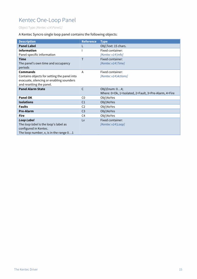
Kentec One-Loop Panel Object Type: [Kentec v14\Panel1]
A Kentec Syncro single loop panel contains the following objects:
Description Reference TypePanel Label L Obj\Text: 15 chars.Information Panel-specific information
I Fixed container:[Kentec v14\Info]
Time The panel’s own time and occupancy periods
T Fixed container:[Kentec v14\Time]
Commands Contains objects for setting the panel into evacuate, silencing or enabling sounders and resetting the panel.
A Fixed container:[Kentec v14\Actions]
Panel Alarm State C Obj\Enum: 0…4;Where: 0=Ok, 1=Isolated, 2=Fault, 3=Pre-Alarm, 4=Fire
Panel OK C0 Obj\NoYesIsolations C1 Obj\NoYesFaults C2 Obj\NoYesPre-Alarm C3 Obj\NoYesFire C4 Obj\NoYesLoop Label The loop label is the loop’s label as configured in Kentec. The loop number, x, is in the range 0…1
Lx Fixed container:[Kentec v14\Loop]

The Kentec Driver 16
Kentec Two-Loop Panel Object Type: [Kentec v14\Panel2]
A Kentec Syncro two loop Panel contains the following objects:
Description Reference TypePanel Label L Obj\Text: 15 chars.Information Panel-specific information
I Fixed container:[Kentec v14\Info]
Time The panel’s own time and occupancy periods
T Fixed container:[Kentec v14\Time]
Commands Contains objects for setting the panel into evacuate, silencing or enabling sounders and resetting the panel.
A Fixed container:[Kentec v14\Actions]
Panel Alarm State C Obj\Enum: 0…4;Where: 0=Ok, 1=Isolated, 2=Fault, 3=Pre-Alarm, 4=Fire
Panel OK C0 Obj\NoYesIsolations C1 Obj\NoYesFaults C2 Obj\NoYesPre-Alarm C3 Obj\NoYesFire C4 Obj\NoYesLoop Label The loop label is the loop’s label as configured in Kentec. The loop number, x, is in the range 0…2
Lx Fixed container:[Kentec v14\Loop]

The Kentec Driver 17
Kentec Four-Loop Panel Object Type: [Kentec v14\Panel4]
A Kentec Syncro four loop panel contains the following objects:
Description Reference TypePanel Label L Obj\Text: 15 chars.Information Panel-specific information
I Fixed container:[Kentec v14\Info]
Time The panel’s own time and occupancy periods
T Fixed container:[Kentec v14\Time]
Commands Contains objects for setting the panel into evacuate, silencing or enabling sounders and resetting the panel.
A Fixed container:[Kentec v14\Actions]
Panel Alarm State C Obj\Enum: 0…4;Where: 0=Ok, 1=Isolated, 2=Fault, 3=Pre-Alarm, 4=Fire
Panel OK C0 Obj\NoYesIsolations C1 Obj\NoYesFaults C2 Obj\NoYesPre-Alarm C3 Obj\NoYesFire C4 Obj\NoYesLoop Label The loop label is the loop’s label as configured in Kentec. The loop number, x, is in the range 0…4.
Lx Fixed container:[Kentec v14\Loop]

The Kentec Driver 18
Zone Object Type: [Kentec v14\Zone]
A Kentec zone contains the following objects:
Description Reference TypeZone Alarm State C Obj\Enum: 0…4;
Where: 0=Ok, 1=Isolated, 2=Fault, 3=Pre-Alarm, 4=Fire. Adjustable: 0=Deisolate, 1=Isolate
Zone OK C0 Obj\NoYesZone Devices Isolated Indicates whether devices in this zone are isolated. Can be written to in order to isolate or de-isolate a zone
C1 Obj\NoYes; Adjustable
Zone Devices in Fault C2 Obj\NoYesZone Devices in Pre-Alarm C3 Obj\NoYesZone Devices in Fire C4 Obj\NoYes

The Kentec Driver 19
Information Object Type: [Kentec v14\Info]
The panel information object contains the following objects:
Description Reference TypePanel Label
L Obj\Text: 15 chars.
Supplier Label SL Obj\TextSoftware Version The software version of the Kentec panel
SV Obj\Text

The Kentec Driver 20
Time Object Type: [Kentec v14\Time]
The Kentec time object contains the following objects:
Description Reference TypeSet Panel Date & Time TIME Obj\DateTime; Adjustable only Sunday Occupation D1 Obj\Times; 1 PeriodMonday Occupation D2 Obj\Times; 1 PeriodTuesday Occupation D3 Obj\Times; 1 PeriodWednesday Occupation D4 Obj\Times; 1 PeriodThursday Occupation D5 Obj\Times; 1 PeriodFriday Occupation D6 Obj\Times; 1 PeriodSaturday Occupation D7 Obj\Times; 1 Period

The Kentec Driver 21
Commands Object Type: [Kentec v14\Actions]
The Kentec panel commands object contains the following objects:
Description Reference TypeReset Panel Performs a reset on the panel
R Obj\NoYes; Adjustable only
Sounders Disables or enables sounders
S Obj\NoYes; Adjustable
Evacuate Sets the panel into evacuation mode
E Obj\NoYes; Adjustable only

The Kentec Driver 22
Loop Object Type: [Kentec v14\Loop]
A Kentec panel loop contains the following objects. Loop 0 is used to reference on-panel I/O.
Description Reference TypeLabel When the panel is configured with a loop offset, this indicates the actual loop number
L Obj\Text
Loop Alarm State C Obj\Enum: 0…4; Where: 0=Ok, 1=Isolated, 2=Fault, 3=Pre-Alarm, 4=Fire
Loop OK C0 Obj\NoYesLoop Devices Isolated C1 Obj\NoYesLoop Devices in Fault C2 Obj\NoYesLoop Devices in Pre-Alarm C3 Obj\NoYesLoop Devices in Fire C4 Obj\NoYesDevice x The device address, x, is in the range 0…254. Hochiki devices are in the range 0…126, with addressable bases using device+127. Apollo devices in the range 0…125, with addressable bases using device+126. Loop 0 devices are on-panel I/O boards, with device (board) numbers in the range 1…32
Dx Variable container, can be one of the following:Apollo devices S90 Shop Monitor Unit [Kentec v14\Apollo\0] XP Loop Sounder [Kentec v14\Apollo\1] S90 3 Channel Output [Kentec v14\Apollo\2] S90 Ionisation Unit [Kentec v14\Apollo\3] S90 Zone Monitor Unit [Kentec v14\Apollo\4] S90 Photoelectric Unit [Kentec v14\Apollo\5] S90 Heat Sensor [Kentec v14\Apollo\6] S90 Call Point [Kentec v14\Apollo\7] S90 1 Channel Output Unit [Kentec v14\Apollo\34] S90 Control Unit Monitor [Kentec v14\Apollo\36] S90 Call Point Monitor [Kentec v14\Apollo\39] S90 Sounder CCT Module [Kentec v14\Apollo\65] S90 Switch Monitor Unit [Kentec v14\Apollo\66] S90 Sounder Control Unit [Kentec v14\Apollo\129] XP 3 Channel Input Output Unit [Kentec v14\Apollo\130] XP Ionisation Unit [Kentec v14\Apollo\131] XP Zone Monitor Units [Kentec v14\Apollo\132] XP Photoelectric Unit [Kentec v14\Apollo\133] XP Heat Sensor Unit [Kentec v14\Apollo\134] XP Switch Monitor Unit [Kentec v14\Apollo\140] XP Intelligent Beam Unit [Kentec v14\Apollo\141] XP High Temperature Sensor [Kentec v14\Apollo\142] XP Flame Detector [Kentec v14\Apollo\149] XP Multi Photo Unit [Kentec v14\Apollo\157] XP Call Point [Kentec v14\Apollo\159] XP Output Unit [Kentec v14\Apollo\162] D Ionisation Unit [Kentec v14\Apollo\163] D Photoelectric Unit [Kentec v14\Apollo\165] D Heat Sensor Unit [Kentec v14\Apollo\166] D Gaseous Fire Sensor [Kentec v14\Apollo\171] XP Switch Monitor Plus [Kentec v14\Apollo\172] D SBB Base Sounder [Kentec v14\Apollo\177] D Multi Photo Unit [Kentec v14\Apollo\181] D Dual Sensor [Kentec v14\Apollo\189] D Call Point [Kentec v14\Apollo\191] XP Radio Sensor [Kentec v14\Apollo\196] D Gaseous Fire Sensor [Kentec v14\Apollo\197] D Gaseous Fire Sensor [Kentec v14\Apollo\204] D Gaseous Fire Sensor [Kentec v14\Apollo\223]

The Kentec Driver 23
Description Reference TypeHochiki DevicesCall Point [Kentec v14\Hochiki\0] Base Module [Kentec v14\Hochiki\18] Base Master [Kentec v14\Hochiki\20] Mini Zone [Kentec v14\Hochiki\21] Loops Controller [Kentec v14\Hochiki\25] Switch Module [Kentec v14\Hochiki\57] Loop Beacon [Kentec v14\Hochiki\65] ADR Remote IND [Kentec v14\Hochiki\66] Loop Sounder [Kentec v14\Hochiki\94] Bell Module [Kentec v14\Hochiki\120] Multi IO Module [Kentec v14\Hochiki\122] Output Module [Kentec v14\Hochiki\124] Single IO Module [Kentec v14\Hochiki\125] POM Output Module [Kentec v14\Hochiki\126] Photoelectric [Kentec v14\Hochiki\136] Heat Sensor [Kentec v14\Hochiki\152] Heat Sensor ACB [Kentec v14\Hochiki\153] Ionisation Unit [Kentec v14\Hochiki\168] Multi Sensor [Kentec v14\Hochiki\216] Loop 0 Devices I/O Board [Kentec v14\IOBoard]

The Kentec Driver 24
S90 Shop Monitor Unit Object Type: [Kentec v14\Apollo\0]
The Apollo S90 Shop Monitor Unit contains the following objects:
Description Reference TypeDevice Alarm State C Obj\Enum: 0…4;
Where: 0=Ok, 1=Isolated, 2=Fault, 3=Pre-Alarm, 4=Fire. Adjustable: 0=Deisolate, 1=Isolate
Device OK
C0 Obj\NoYes
Device Isolated Indicates if this device or sub-addresses are isolated. Can be written to in order to isolate or de-isolate the device
C1 Obj\NoYes; Adjustable
Device in Fault
C2 Obj\NoYes
Device in Pre-Alarm Can also cover technical and security alarms where applicable
C3 Obj\NoYes
Device in Fire
C4 Obj\NoYes
Sub-address x The sub-address number, x, is in the range 1…3
Sx Fixed Container:[Kentec v14\SubAddr]

The Kentec Driver 25
XP Loop Sounder Object Type: [Kentec v14\Apollo\1]
The Apollo XP Loop Sounder contains the following objects:
Description Reference TypeDevice Alarm State C Obj\Enum: 0…4;
Where: 0=Ok, 1=Isolated, 2=Fault, 3=Pre-Alarm, 4=Fire. Adjustable: 0=Deisolate, 1=Isolate
Device OK
C0 Obj\NoYes
Device Isolated Indicates whether this device is isolated. Can be written to in order to isolate or de-isolate the device
C1 Obj\NoYes; Adjustable
Device in Fault
C2 Obj\NoYes
Device in Pre-Alarm Can also cover technical and security alarms where applicable
C3 Obj\NoYes
Device in Fire
C4 Obj\NoYes

The Kentec Driver 26
S90 3 Channel Output Object Type: [Kentec v14\Apollo\2]
The Apollo S90 3 Channel Output contains the following objects:
Description Reference TypeDevice Alarm State C Obj\Enum: 0…4;
Where: 0=Ok, 1=Isolated, 2=Fault, 3=Pre-Alarm, 4=Fire. Adjustable: 0=Deisolate, 1=Isolate
Device OK
C0 Obj\NoYes
Device Isolated Indicates if this device or sub-addresses are isolated. Can be written to in order to isolate or de-isolate the device
C1 Obj\NoYes; Adjustable
Device in Fault
C2 Obj\NoYes
Device in Pre-Alarm Can also cover technical and security alarms where applicable
C3 Obj\NoYes
Device in Fire
C4 Obj\NoYes
Sub-address x The sub-address number, x, is in the range 1…6
Sx Fixed Container:[Kentec v14\SubAddr]

The Kentec Driver 27
S90 Ionisation Unit Object Type: [Kentec v14\Apollo\3]
The Apollo S90 Ionisation Unit contains the following objects:
Description Reference TypeDevice Alarm State C Obj\Enum: 0…4;
Where: 0=Ok, 1=Isolated, 2=Fault, 3=Pre-Alarm, 4=Fire. Adjustable: 0=Deisolate, 1=Isolate
Device OK
C0 Obj\NoYes
Device Isolated Indicates whether this device is isolated. Can be written to in order to isolate or de-isolate the device
C1 Obj\NoYes; Adjustable
Device in Fault
C2 Obj\NoYes
Device in Pre-Alarm Can also cover technical and security alarms where applicable
C3 Obj\NoYes
Device in Fire
C4 Obj\NoYes
The Kentec Driver 28
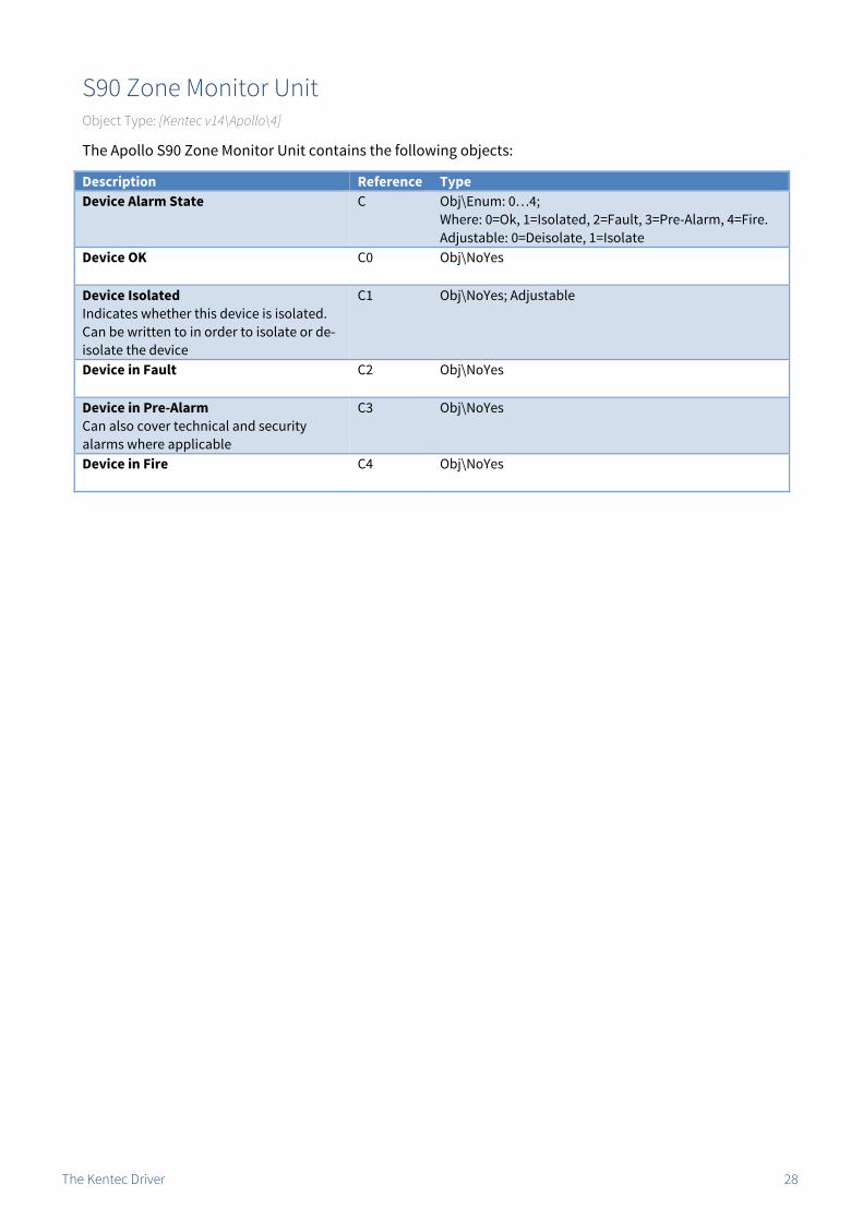
S90 Zone Monitor Unit Object Type: [Kentec v14\Apollo\4]
The Apollo S90 Zone Monitor Unit contains the following objects:
Description Reference TypeDevice Alarm State C Obj\Enum: 0…4;
Where: 0=Ok, 1=Isolated, 2=Fault, 3=Pre-Alarm, 4=Fire. Adjustable: 0=Deisolate, 1=Isolate
Device OK
C0 Obj\NoYes
Device Isolated Indicates whether this device is isolated. Can be written to in order to isolate or de-isolate the device
C1 Obj\NoYes; Adjustable
Device in Fault
C2 Obj\NoYes
Device in Pre-Alarm Can also cover technical and security alarms where applicable
C3 Obj\NoYes
Device in Fire
C4 Obj\NoYes

The Kentec Driver 29
S90 Photoelectric Unit Object Type: [Kentec v14\Apollo\5]
The Apollo S90 Photoelectric Unit contains the following objects:
Description Reference TypeDevice Alarm State C Obj\Enum: 0…4;
Where: 0=Ok, 1=Isolated, 2=Fault, 3=Pre-Alarm, 4=Fire. Adjustable: 0=Deisolate, 1=Isolate
Device OK
C0 Obj\NoYes
Device Isolated Indicates whether this device is isolated. Can be written to in order to isolate or de-isolate the device
C1 Obj\NoYes; Adjustable
Device in Fault
C2 Obj\NoYes
Device in Pre-Alarm Can also cover technical and security alarms where applicable
C3 Obj\NoYes
Device in Fire
C4 Obj\NoYes

The Kentec Driver 30
S90 Heat Sensor Object Type: [Kentec v14\Apollo\6]
The Apollo S90 Heat Sensor contains the following objects:
Description Reference TypeDevice Alarm State C Obj\Enum: 0…4;
Where: 0=Ok, 1=Isolated, 2=Fault, 3=Pre-Alarm, 4=Fire. Adjustable: 0=Deisolate, 1=Isolate
Device OK
C0 Obj\NoYes
Device Isolated Indicates whether this device is isolated. Can be written to in order to isolate or de-isolate the device
C1 Obj\NoYes; Adjustable
Device in Fault
C2 Obj\NoYes
Device in Pre-Alarm Can also cover technical and security alarms where applicable
C3 Obj\NoYes
Device in Fire
C4 Obj\NoYes

The Kentec Driver 31
S90 Call Point Object Type: [Kentec v14\Apollo\7]
The Apollo S90 Call Point contains the following objects:
Description Reference TypeDevice Alarm State C Obj\Enum: 0…4;
Where: 0=Ok, 1=Isolated, 2=Fault, 3=Pre-Alarm, 4=Fire. Adjustable: 0=Deisolate, 1=Isolate
Device OK
C0 Obj\NoYes
Device Isolated Indicates whether this device is isolated. Can be written to in order to isolate or de-isolate the device
C1 Obj\NoYes; Adjustable
Device in Fault
C2 Obj\NoYes
Device in Pre-Alarm Can also cover technical and security alarms where applicable
C3 Obj\NoYes
Device in Fire
C4 Obj\NoYes
The Kentec Driver 32
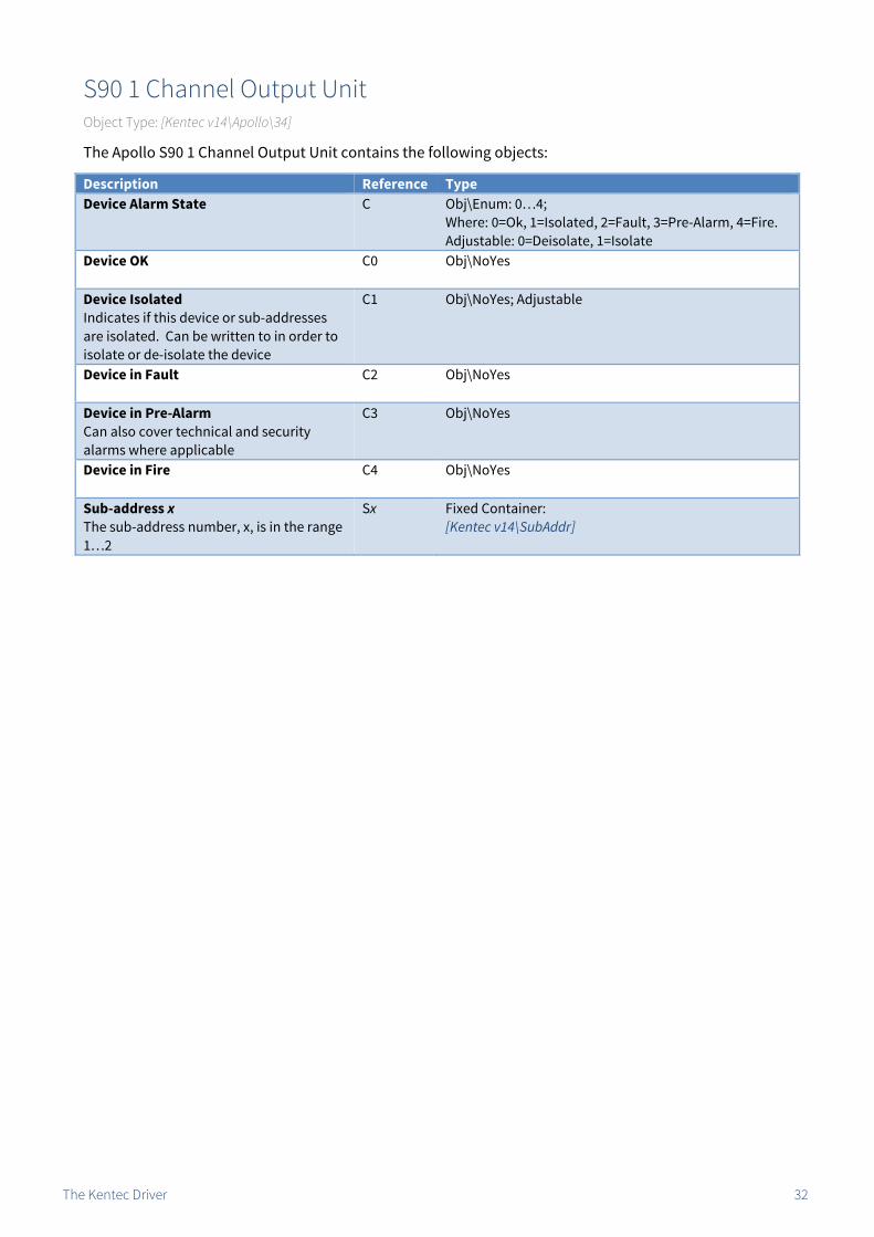
S90 1 Channel Output Unit Object Type: [Kentec v14\Apollo\34]
The Apollo S90 1 Channel Output Unit contains the following objects:
Description Reference TypeDevice Alarm State C Obj\Enum: 0…4;
Where: 0=Ok, 1=Isolated, 2=Fault, 3=Pre-Alarm, 4=Fire. Adjustable: 0=Deisolate, 1=Isolate
Device OK
C0 Obj\NoYes
Device Isolated Indicates if this device or sub-addresses are isolated. Can be written to in order to isolate or de-isolate the device
C1 Obj\NoYes; Adjustable
Device in Fault
C2 Obj\NoYes
Device in Pre-Alarm Can also cover technical and security alarms where applicable
C3 Obj\NoYes
Device in Fire
C4 Obj\NoYes
Sub-address x The sub-address number, x, is in the range 1…2
Sx Fixed Container:[Kentec v14\SubAddr]

The Kentec Driver 33
S90 Control Unit Monitor Object Type: [Kentec v14\Apollo\36]
The Apollo S90 Control Unit Monitor contains the following objects:
Description Reference TypeDevice Alarm State C Obj\Enum: 0…4;
Where: 0=Ok, 1=Isolated, 2=Fault, 3=Pre-Alarm, 4=Fire. Adjustable: 0=Deisolate, 1=Isolate
Device OK
C0 Obj\NoYes
Device Isolated Indicates whether this device is isolated. Can be written to in order to isolate or de-isolate the device
C1 Obj\NoYes; Adjustable
Device in Fault
C2 Obj\NoYes
Device in Pre-Alarm Can also cover technical and security alarms where applicable
C3 Obj\NoYes
Device in Fire
C4 Obj\NoYes

The Kentec Driver 34
S90 Call Point Monitor Object Type: [Kentec v14\Apollo\39]
The Apollo S90 Call Point Monitor contains the following objects:
Description Reference TypeDevice Alarm State C Obj\Enum: 0…4;
Where: 0=Ok, 1=Isolated, 2=Fault, 3=Pre-Alarm, 4=Fire. Adjustable: 0=Deisolate, 1=Isolate
Device OK
C0 Obj\NoYes
Device Isolated Indicates whether this device is isolated. Can be written to in order to isolate or de-isolate the device
C1 Obj\NoYes; Adjustable
Device in Fault
C2 Obj\NoYes
Device in Pre-Alarm Can also cover technical and security alarms where applicable
C3 Obj\NoYes
Device in Fire
C4 Obj\NoYes

The Kentec Driver 35
S90 Sounder CCT Controller Object Type: [Kentec v14\Apollo\65]
The Apollo S90 Sounder CCT Controller contains the following objects:
Description Reference TypeDevice Alarm State C Obj\Enum: 0…4;
Where: 0=Ok, 1=Isolated, 2=Fault, 3=Pre-Alarm, 4=Fire. Adjustable: 0=Deisolate, 1=Isolate
Device OK
C0 Obj\NoYes
Device Isolated Indicates whether this device is isolated. Can be written to in order to isolate or de-isolate the device
C1 Obj\NoYes; Adjustable
Device in Fault
C2 Obj\NoYes
Device in Pre-Alarm Can also cover technical and security alarms where applicable
C3 Obj\NoYes
Device in Fire
C4 Obj\NoYes

The Kentec Driver 36
S90 Switch Monitor Unit Object Type: [Kentec v14\Apollo\66]
The Apollo S90 Switch Monitor Unit contains the following objects:
Description Reference TypeDevice Alarm State C Obj\Enum: 0…4;
Where: 0=Ok, 1=Isolated, 2=Fault, 3=Pre-Alarm, 4=Fire. Adjustable: 0=Deisolate, 1=Isolate
Device OK
C0 Obj\NoYes
Device Isolated Indicates if this device or sub-address is isolated. Can be written to in order to isolate or de-isolate the device
C1 Obj\NoYes; Adjustable
Device in Fault
C2 Obj\NoYes
Device in Pre-Alarm Can also cover technical and security alarms where applicable
C3 Obj\NoYes
Device in Fire
C4 Obj\NoYes
Sub-address 1
S1 Fixed Container:[Kentec v14\SubAddr]

The Kentec Driver 37
S90 Sounder Control Unit Object Type: [Kentec v14\Apollo\129]
The Apollo S90 Sounder Control Unit contains the following objects:
Description Reference TypeDevice Alarm State C Obj\Enum: 0…4;
Where: 0=Ok, 1=Isolated, 2=Fault, 3=Pre-Alarm, 4=Fire. Adjustable: 0=Deisolate, 1=Isolate
Device OK
C0 Obj\NoYes
Device Isolated Indicates whether this device is isolated. Can be written to in order to isolate or de-isolate the device
C1 Obj\NoYes; Adjustable
Device in Fault
C2 Obj\NoYes
Device in Pre-Alarm Can also cover technical and security alarms where applicable
C3 Obj\NoYes
Device in Fire
C4 Obj\NoYes

The Kentec Driver 38
XP 3 Channel Input Output Unit Object Type: [Kentec v14\Apollo\130]
The Apollo XP 3 Channel Input Output Unit contains the following objects:
Description Reference TypeDevice Alarm State C Obj\Enum: 0…4;
Where: 0=Ok, 1=Isolated, 2=Fault, 3=Pre-Alarm, 4=Fire. Adjustable: 0=Deisolate, 1=Isolate
Device OK
C0 Obj\NoYes
Device Isolated Indicates whether this device is isolated. Can be written to in order to isolate or de-isolate the device
C1 Obj\NoYes; Adjustable
Device in Fault
C2 Obj\NoYes
Device in Pre-Alarm Can also cover technical and security alarms where applicable
C3 Obj\NoYes
Device in Fire
C4 Obj\NoYes

The Kentec Driver 39
XP Ionisation Unit Object Type: [Kentec v14\Apollo\131]
The Apollo XP Ionisation Unit contains the following objects:
Description Reference TypeDevice Alarm State C Obj\Enum: 0…4;
Where: 0=Ok, 1=Isolated, 2=Fault, 3=Pre-Alarm, 4=Fire. Adjustable: 0=Deisolate, 1=Isolate
Device OK
C0 Obj\NoYes
Device Isolated Indicates whether this device is isolated. Can be written to in order to isolate or de-isolate the device
C1 Obj\NoYes; Adjustable
Device in Fault
C2 Obj\NoYes
Device in Pre-Alarm Can also cover technical and security alarms where applicable
C3 Obj\NoYes
Device in Fire
C4 Obj\NoYes

The Kentec Driver 40
XP Zone Monitor Units Object Type: [Kentec v14\Apollo\132]
The Apollo XP Zone Monitor Unit contains the following objects:
Description Reference TypeDevice Alarm State C Obj\Enum: 0…4;
Where: 0=Ok, 1=Isolated, 2=Fault, 3=Pre-Alarm, 4=Fire. Adjustable: 0=Deisolate, 1=Isolate
Device OK
C0 Obj\NoYes
Device Isolated Indicates whether this device is isolated. Can be written to in order to isolate or de-isolate the device
C1 Obj\NoYes; Adjustable
Device in Fault
C2 Obj\NoYes
Device in Pre-Alarm Can also cover technical and security alarms where applicable
C3 Obj\NoYes
Device in Fire
C4 Obj\NoYes

The Kentec Driver 41
XP Photoelectric Unit Object Type: [Kentec v14\Apollo\133]
The Apollo XP Photoelectric Unit contains the following objects:
Description Reference TypeDevice Alarm State C Obj\Enum: 0…4;
Where: 0=Ok, 1=Isolated, 2=Fault, 3=Pre-Alarm, 4=Fire. Adjustable: 0=Deisolate, 1=Isolate
Device OK
C0 Obj\NoYes
Device Isolated Indicates whether this device is isolated. Can be written to in order to isolate or de-isolate the device
C1 Obj\NoYes; Adjustable
Device in Fault
C2 Obj\NoYes
Device in Pre-Alarm Can also cover technical and security alarms where applicable
C3 Obj\NoYes
Device in Fire
C4 Obj\NoYes

The Kentec Driver 42
XP Heat Sensor Unit Object Type: [Kentec v14\Apollo\134]
The Apollo XP Heat Sensor Unit contains the following objects:
Description Reference TypeDevice Alarm State C Obj\Enum: 0…4;
Where: 0=Ok, 1=Isolated, 2=Fault, 3=Pre-Alarm, 4=Fire. Adjustable: 0=Deisolate, 1=Isolate
Device OK
C0 Obj\NoYes
Device Isolated Indicates whether this device is isolated. Can be written to in order to isolate or de-isolate the device
C1 Obj\NoYes; Adjustable
Device in Fault
C2 Obj\NoYes
Device in Pre-Alarm Can also cover technical and security alarms where applicable
C3 Obj\NoYes
Device in Fire
C4 Obj\NoYes

The Kentec Driver 43
XP Switch Monitor Unit Object Type: [Kentec v14\Apollo\140]
The Apollo XP Switch Monitor Unit contains the following objects:
Description Reference TypeDevice Alarm State C Obj\Enum: 0…4;
Where: 0=Ok, 1=Isolated, 2=Fault, 3=Pre-Alarm, 4=Fire. Adjustable: 0=Deisolate, 1=Isolate
Device OK
C0 Obj\NoYes
Device Isolated Indicates if this device or sub-address is isolated. Can be written to in order to isolate or de-isolate the device
C1 Obj\NoYes; Adjustable
Device in Fault
C2 Obj\NoYes
Device in Pre-Alarm Can also cover technical and security alarms where applicable
C3 Obj\NoYes
Device in Fire
C4 Obj\NoYes
Sub-address 1
S1 Fixed Container:[Kentec v14\SubAddr]

The Kentec Driver 44
XP Intelligent Beam Unit Object Type: [Kentec v14\Apollo\141]
The Apollo XP Intelligent Beam contains the following objects:
Description Reference TypeDevice Alarm State C Obj\Enum: 0…4;
Where: 0=Ok, 1=Isolated, 2=Fault, 3=Pre-Alarm, 4=Fire. Adjustable: 0=Deisolate, 1=Isolate
Device OK
C0 Obj\NoYes
Device Isolated Indicates whether this device is isolated. Can be written to in order to isolate or de-isolate the device
C1 Obj\NoYes; Adjustable
Device in Fault
C2 Obj\NoYes
Device in Pre-Alarm Can also cover technical and security alarms where applicable
C3 Obj\NoYes
Device in Fire
C4 Obj\NoYes

The Kentec Driver 45
XP High Temperature Sensor Object Type: [Kentec v14\Apollo\142]
The Apollo XP High Temperature Sensor contains the following objects:
Description Reference TypeDevice Alarm State C Obj\Enum: 0…4;
Where: 0=Ok, 1=Isolated, 2=Fault, 3=Pre-Alarm, 4=Fire. Adjustable: 0=Deisolate, 1=Isolate
Device OK
C0 Obj\NoYes
Device Isolated Indicates whether this device is isolated. Can be written to in order to isolate or de-isolate the device
C1 Obj\NoYes; Adjustable
Device in Fault
C2 Obj\NoYes
Device in Pre-Alarm Can also cover technical and security alarms where applicable
C3 Obj\NoYes
Device in Fire
C4 Obj\NoYes

The Kentec Driver 46
XP Flame Detector Object Type: [Kentec v14\Apollo\149]
The Apollo XP Flame Detector contains the following objects:
Description Reference TypeDevice Alarm State C Obj\Enum: 0…4;
Where: 0=Ok, 1=Isolated, 2=Fault, 3=Pre-Alarm, 4=Fire. Adjustable: 0=Deisolate, 1=Isolate
Device OK
C0 Obj\NoYes
Device Isolated Indicates whether this device is isolated. Can be written to in order to isolate or de-isolate the device
C1 Obj\NoYes; Adjustable
Device in Fault
C2 Obj\NoYes
Device in Pre-Alarm Can also cover technical and security alarms where applicable
C3 Obj\NoYes
Device in Fire
C4 Obj\NoYes

The Kentec Driver 47
XP Multi Photo Unit Object Type: [Kentec v14\Apollo\157]
The Apollo XP Multi Photo Unit contains the following objects:
Description Reference TypeDevice Alarm State C Obj\Enum: 0…4;
Where: 0=Ok, 1=Isolated, 2=Fault, 3=Pre-Alarm, 4=Fire. Adjustable: 0=Deisolate, 1=Isolate
Device OK
C0 Obj\NoYes
Device Isolated Indicates whether this device is isolated. Can be written to in order to isolate or de-isolate the device
C1 Obj\NoYes; Adjustable
Device in Fault
C2 Obj\NoYes
Device in Pre-Alarm Can also cover technical and security alarms where applicable
C3 Obj\NoYes
Device in Fire
C4 Obj\NoYes

The Kentec Driver 48
XP Call Point Object Type: [Kentec v14\Apollo\159]
The Apollo XP Call Point contains the following objects:
Description Reference TypeDevice Alarm State C Obj\Enum: 0…4;
Where: 0=Ok, 1=Isolated, 2=Fault, 3=Pre-Alarm, 4=Fire. Adjustable: 0=Deisolate, 1=Isolate
Device OK
C0 Obj\NoYes
Device Isolated Indicates whether this device is isolated. Can be written to in order to isolate or de-isolate the device
C1 Obj\NoYes; Adjustable
Device in Fault
C2 Obj\NoYes
Device in Pre-Alarm Can also cover technical and security alarms where applicable
C3 Obj\NoYes
Device in Fire
C4 Obj\NoYes

The Kentec Driver 49
XP Output Unit Object Type: [Kentec v14\Apollo\162]
The Apollo XP Output Unit contains the following objects:
Description Reference TypeDevice Alarm State C Obj\Enum: 0…4;
Where: 0=Ok, 1=Isolated, 2=Fault, 3=Pre-Alarm, 4=Fire. Adjustable: 0=Deisolate, 1=Isolate
Device OK
C0 Obj\NoYes
Device Isolated Indicates if this device or sub-address is isolated. Can be written to in order to isolate or de-isolate the device
C1 Obj\NoYes; Adjustable
Device in Fault
C2 Obj\NoYes
Device in Pre-Alarm Can also cover technical and security alarms where applicable
C3 Obj\NoYes
Device in Fire
C4 Obj\NoYes
Sub-address 1
S1 Fixed Container:[Kentec v14\SubAddr]

The Kentec Driver 50
D Ionisation Unit Object Type: [Kentec v14\Apollo\163]
The Apollo D Ionisation Unit contains the following objects:
Description Reference TypeDevice Alarm State C Obj\Enum: 0…4;
Where: 0=Ok, 1=Isolated, 2=Fault, 3=Pre-Alarm, 4=Fire. Adjustable: 0=Deisolate, 1=Isolate
Device OK
C0 Obj\NoYes
Device Isolated Indicates whether this device is isolated. Can be written to in order to isolate or de-isolate the device
C1 Obj\NoYes; Adjustable
Device in Fault
C2 Obj\NoYes
Device in Pre-Alarm Can also cover technical and security alarms where applicable
C3 Obj\NoYes
Device in Fire
C4 Obj\NoYes

The Kentec Driver 51
D Photoelectric Unit Object Type: [Kentec v14\Apollo\165]
The Apollo D Photoelectric Unit contains the following objects:
Description Reference TypeDevice Alarm State C Obj\Enum: 0…4;
Where: 0=Ok, 1=Isolated, 2=Fault, 3=Pre-Alarm, 4=Fire. Adjustable: 0=Deisolate, 1=Isolate
Device OK
C0 Obj\NoYes
Device Isolated Indicates whether this device is isolated. Can be written to in order to isolate or de-isolate the device
C1 Obj\NoYes; Adjustable
Device in Fault
C2 Obj\NoYes
Device in Pre-Alarm Can also cover technical and security alarms where applicable
C3 Obj\NoYes
Device in Fire
C4 Obj\NoYes

The Kentec Driver 52
D Heat Sensor Unit Object Type: [Kentec v14\Apollo\166]
The Apollo D Heat Sensor Unit contains the following objects:
Description Reference TypeDevice Alarm State C Obj\Enum: 0…4;
Where: 0=Ok, 1=Isolated, 2=Fault, 3=Pre-Alarm, 4=Fire. Adjustable: 0=Deisolate, 1=Isolate
Device OK
C0 Obj\NoYes
Device Isolated Indicates whether this device is isolated. Can be written to in order to isolate or de-isolate the device
C1 Obj\NoYes; Adjustable
Device in Fault
C2 Obj\NoYes
Device in Pre-Alarm Can also cover technical and security alarms where applicable
C3 Obj\NoYes
Device in Fire
C4 Obj\NoYes

The Kentec Driver 53
D Gaseous Fire Sensor Object Type: [Kentec v14\Apollo\171]
The Apollo D Gaseous Fire Sensor contains the following objects:
Description Reference TypeDevice Alarm State C Obj\Enum: 0…4;
Where: 0=Ok, 1=Isolated, 2=Fault, 3=Pre-Alarm, 4=Fire. Adjustable: 0=Deisolate, 1=Isolate
Device OK
C0 Obj\NoYes
Device Isolated Indicates whether this device is isolated. Can be written to in order to isolate or de-isolate the device
C1 Obj\NoYes; Adjustable
Device in Fault
C2 Obj\NoYes
Device in Pre-Alarm Can also cover technical and security alarms where applicable
C3 Obj\NoYes
Device in Fire
C4 Obj\NoYes

The Kentec Driver 54
XP Switch Monitor Plus Object Type: [Kentec v14\Apollo\172]
The Apollo XP Switch Monitor Plus contains the following objects:
Description Reference TypeDevice Alarm State C Obj\Enum: 0…4;
Where: 0=Ok, 1=Isolated, 2=Fault, 3=Pre-Alarm, 4=Fire. Adjustable: 0=Deisolate, 1=Isolate
Device OK
C0 Obj\NoYes
Device Isolated Indicates if this device or sub-addresses are isolated. Can be written to in order to isolate or de-isolate the device
C1 Obj\NoYes; Adjustable
Device in Fault
C2 Obj\NoYes
Device in Pre-Alarm Can also cover technical and security alarms where applicable
C3 Obj\NoYes
Device in Fire
C4 Obj\NoYes
Sub-address 1
S1 Fixed Container:[Kentec v14\SubAddr]
Sub-address 2
S2 Fixed Container:[Kentec v14\SubAddr]

The Kentec Driver 55
D SBB Base Sounder Object Type: [Kentec v14\Apollo\177]
The D SBB Base Sounder contains the following objects:
Description Reference TypeDevice Alarm State C Obj\Enum: 0…4;
Where: 0=Ok, 1=Isolated, 2=Fault, 3=Pre-Alarm, 4=Fire. Adjustable: 0=Deisolate, 1=Isolate
Device OK
C0 Obj\NoYes
Device Isolated Indicates if this device or sub-address is isolated. Can be written to in order to isolate or de-isolate the device
C1 Obj\NoYes; Adjustable
Device in Fault
C2 Obj\NoYes
Device in Pre-Alarm Can also cover technical and security alarms where applicable
C3 Obj\NoYes
Device in Fire
C4 Obj\NoYes
Sub-address 1
S1 Fixed Container:[Kentec v14\SubAddr]

The Kentec Driver 56
D Multi Photo Unit Object Type: [Kentec v14\Apollo\181]
The Multi Photo Unit contains the following objects:
Description Reference TypeDevice Alarm State C Obj\Enum: 0…4;
Where: 0=Ok, 1=Isolated, 2=Fault, 3=Pre-Alarm, 4=Fire. Adjustable: 0=Deisolate, 1=Isolate
Device OK
C0 Obj\NoYes
Device Isolated Indicates whether this device is isolated. Can be written to in order to isolate or de-isolate the device
C1 Obj\NoYes; Adjustable
Device in Fault
C2 Obj\NoYes
Device in Pre-Alarm Can also cover technical and security alarms where applicable
C3 Obj\NoYes
Device in Fire
C4 Obj\NoYes
The Kentec Driver 57
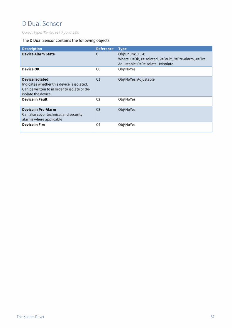
D Dual Sensor Object Type: [Kentec v14\Apollo\189]
The D Dual Sensor contains the following objects:
Description Reference TypeDevice Alarm State C Obj\Enum: 0…4;
Where: 0=Ok, 1=Isolated, 2=Fault, 3=Pre-Alarm, 4=Fire. Adjustable: 0=Deisolate, 1=Isolate
Device OK
C0 Obj\NoYes
Device Isolated Indicates whether this device is isolated. Can be written to in order to isolate or de-isolate the device
C1 Obj\NoYes; Adjustable
Device in Fault
C2 Obj\NoYes
Device in Pre-Alarm Can also cover technical and security alarms where applicable
C3 Obj\NoYes
Device in Fire
C4 Obj\NoYes

The Kentec Driver 58
D Call Point Object Type: [Kentec v14\Apollo\191]
The D Call Point contains the following objects:
Description Reference TypeDevice Alarm State C Obj\Enum: 0…4;
Where: 0=Ok, 1=Isolated, 2=Fault, 3=Pre-Alarm, 4=Fire. Adjustable: 0=Deisolate, 1=Isolate
Device OK
C0 Obj\NoYes
Device Isolated Indicates whether this device is isolated. Can be written to in order to isolate or de-isolate the device
C1 Obj\NoYes; Adjustable
Device in Fault
C2 Obj\NoYes
Device in Pre-Alarm Can also cover technical and security alarms where applicable
C3 Obj\NoYes
Device in Fire
C4 Obj\NoYes

The Kentec Driver 59
XP Radio Sensor Object Type: [Kentec v14\Apollo\196]
The Apollo XP Radio Sensor contains the following objects:
Description Reference TypeDevice Alarm State C Obj\Enum: 0…4;
Where: 0=Ok, 1=Isolated, 2=Fault, 3=Pre-Alarm, 4=Fire. Adjustable: 0=Deisolate, 1=Isolate
Device OK
C0 Obj\NoYes
Device Isolated Indicates whether this device is isolated. Can be written to in order to isolate or de-isolate the device
C1 Obj\NoYes; Adjustable
Device in Fault
C2 Obj\NoYes
Device in Pre-Alarm Can also cover technical and security alarms where applicable
C3 Obj\NoYes
Device in Fire
C4 Obj\NoYes

The Kentec Driver 60
XP Beam Object Type: [Kentec v14\Apollo\197]
The Apollo XP Beam contains the following objects:
Description Reference TypeDevice Alarm State C Obj\Enum: 0…4;
Where: 0=Ok, 1=Isolated, 2=Fault, 3=Pre-Alarm, 4=Fire. Adjustable: 0=Deisolate, 1=Isolate
Device OK
C0 Obj\NoYes
Device Isolated Indicates whether this device is isolated. Can be written to in order to isolate or de-isolate the device
C1 Obj\NoYes; Adjustable
Device in Fault
C2 Obj\NoYes
Device in Pre-Alarm Can also cover technical and security alarms where applicable
C3 Obj\NoYes
Device in Fire
C4 Obj\NoYes

The Kentec Driver 61
XP Mini Switch Monitor Object Type: [Kentec v14\Apollo\204]
The Apollo XP Mini Switch Monitor contains the following objects:
Description Reference TypeDevice Alarm State C Obj\Enum: 0…4;
Where: 0=Ok, 1=Isolated, 2=Fault, 3=Pre-Alarm, 4=Fire. Adjustable: 0=Deisolate, 1=Isolate
Device OK
C0 Obj\NoYes
Device Isolated Indicates if this device or sub-address is isolated. Can be written to in order to isolate or de-isolate the device
C1 Obj\NoYes; Adjustable
Device in Fault
C2 Obj\NoYes
Device in Pre-Alarm Can also cover technical and security alarms where applicable
C3 Obj\NoYes
Device in Fire
C4 Obj\NoYes
Sub-address 1
S1 Fixed Container:[Kentec v14\SubAddr]

The Kentec Driver 62
XP Mini Switch Interrupt Object Type: [Kentec v14\Apollo\223]
The Apollo XP Mini Switch Interrupt contains the following objects:
Description Reference TypeDevice Alarm State C Obj\Enum: 0…4;
Where: 0=Ok, 1=Isolated, 2=Fault, 3=Pre-Alarm, 4=Fire. Adjustable: 0=Deisolate, 1=Isolate
Device OK
C0 Obj\NoYes
Device Isolated Indicates if this device or sub-address is isolated. Can be written to in order to isolate or de-isolate the device
C1 Obj\NoYes; Adjustable
Device in Fault
C2 Obj\NoYes
Device in Pre-Alarm Can also cover technical and security alarms where applicable
C3 Obj\NoYes
Device in Fire
C4 Obj\NoYes
Sub Address 1
S1 Fixed Container:[Kentec v14\SubAddr]

The Kentec Driver 63
Hochiki Call Point Object Type: [Kentec v14\Hochiki\0]
The Hochiki Call Point contains the following objects:
Description Reference TypeDevice Alarm State C Obj\Enum: 0…4;
Where: 0=Ok, 1=Isolated, 2=Fault, 3=Pre-Alarm, 4=Fire. Adjustable: 0=Deisolate, 1=Isolate
Device OK
C0 Obj\NoYes
Device Isolated Indicates whether this device is isolated. Can be written to in order to isolate or de-isolate the device
C1 Obj\NoYes; Adjustable
Device in Fault
C2 Obj\NoYes
Device in Pre-Alarm Can also cover technical and security alarms where applicable
C3 Obj\NoYes
Device in Fire
C4 Obj\NoYes

The Kentec Driver 64
Hochiki Base Module Object Type: [Kentec v14\Hochiki\18]
The Hochiki Base Module contains the following objects:
Description Reference TypeDevice Alarm State C Obj\Enum: 0…4;
Where: 0=Ok, 1=Isolated, 2=Fault, 3=Pre-Alarm, 4=Fire. Adjustable: 0=Deisolate, 1=Isolate
Device OK
C0 Obj\NoYes
Device Isolated Indicates whether this device is isolated. Can be written to in order to isolate or de-isolate the device
C1 Obj\NoYes; Adjustable
Device in Fault
C2 Obj\NoYes
Device in Pre-Alarm Can also cover technical and security alarms where applicable
C3 Obj\NoYes
Device in Fire
C4 Obj\NoYes

The Kentec Driver 65
Hochiki Base Master Object Type: [Kentec v14\Hochiki\20]
The Hochiki Base Master contains the following objects:
Description Reference TypeDevice Alarm State C Obj\Enum: 0…4;
Where: 0=Ok, 1=Isolated, 2=Fault, 3=Pre-Alarm, 4=Fire. Adjustable: 0=Deisolate, 1=Isolate
Device OK
C0 Obj\NoYes
Device Isolated Indicates whether this device is isolated. Can be written to in order to isolate or de-isolate the device
C1 Obj\NoYes; Adjustable
Device in Fault
C2 Obj\NoYes
Device in Pre-Alarm Can also cover technical and security alarms where applicable
C3 Obj\NoYes

The Kentec Driver 66
Hochiki Mini Zone Object Type: [Kentec v14\Hochiki\21]
The Hochiki Base Module contains the following objects:
Description Reference TypeDevice Alarm State C Obj\Enum: 0…4;
Where: 0=Ok, 1=Isolated, 2=Fault, 3=Pre-Alarm, 4=Fire. Adjustable: 0=Deisolate, 1=Isolate
Device OK
C0 Obj\NoYes
Device Isolated Indicates whether this device is isolated. Can be written to in order to isolate or de-isolate the device
C1 Obj\NoYes; Adjustable
Device in Fault
C2 Obj\NoYes
Device in Pre-Alarm Can also cover technical and security alarms where applicable
C3 Obj\NoYes
Device in Fire
C4 Obj\NoYes

The Kentec Driver 67
Hochiki Loops Controller Object Type: [Kentec v14\Hochiki\25]
The Hochiki Loops Controller contains the following objects:
Description Reference TypeDevice Alarm State C Obj\Enum: 0…4;
Where: 0=Ok, 1=Isolated, 2=Fault, 3=Pre-Alarm, 4=Fire. Adjustable: 0=Deisolate, 1=Isolate
Device OK
C0 Obj\NoYes
Device Isolated Indicates whether this device is isolated. Can be written to in order to isolate or de-isolate the device
C1 Obj\NoYes; Adjustable
Device in Fault
C2 Obj\NoYes
Device in Pre-Alarm Can also cover technical and security alarms where applicable
C3 Obj\NoYes
Device in Fire
C4 Obj\NoYes

The Kentec Driver 68
Hochiki Switch Module Object Type: [Kentec v14\Hochiki\57]
The Hochiki Switch Module contains the following objects:
Description Reference TypeDevice Alarm State C Obj\Enum: 0…4;
Where: 0=Ok, 1=Isolated, 2=Fault, 3=Pre-Alarm, 4=Fire. Adjustable: 0=Deisolate, 1=Isolate
Device OK
C0 Obj\NoYes
Device Isolated Indicates if this device or sub-addresses are isolated. Can be written to in order to isolate or de-isolate the device
C1 Obj\NoYes; Adjustable
Device in Fault
C2 Obj\NoYes
Device in Pre-Alarm Can also cover technical and security alarms where applicable
C3 Obj\NoYes
Device in Fire
C4 Obj\NoYes
Sub-address x x is in the range 1..2
Sx Fixed Container:[Kentec v14\SubAddr]

The Kentec Driver 69
Hochiki Loop Beacon Object Type: [Kentec v14\Hochiki\65]
The Hochiki Loop Beacon contains the following objects:
Description Reference TypeDevice Alarm State C Obj\Enum: 0…4;
Where: 0=Ok, 1=Isolated, 2=Fault, 3=Pre-Alarm, 4=Fire. Adjustable: 0=Deisolate, 1=Isolate
Device OK
C0 Obj\NoYes
Device Isolated Indicates whether this device is isolated. Can be written to in order to isolate or de-isolate the device
C1 Obj\NoYes; Adjustable
Device in Fault
C2 Obj\NoYes
Device in Pre-Alarm Can also cover technical and security alarms where applicable
C3 Obj\NoYes
Device in Fire
C4 Obj\NoYes

The Kentec Driver 70
Hochiki ADR Remote IND Object Type: [Kentec v14\Hochiki\66]
The Hochiki ADR Remote IND contains the following objects:
Description Reference TypeDevice Alarm State C Obj\Enum: 0…4;
Where: 0=Ok, 1=Isolated, 2=Fault, 3=Pre-Alarm, 4=Fire. Adjustable: 0=Deisolate, 1=Isolate
Device OK
C0 Obj\NoYes
Device Isolated Indicates whether this device is isolated. Can be written to in order to isolate or de-isolate the device
C1 Obj\NoYes; Adjustable
Device in Fault
C2 Obj\NoYes
Device in Pre-Alarm Can also cover technical and security alarms where applicable
C3 Obj\NoYes
Device in Fire
C4 Obj\NoYes

The Kentec Driver 71
Hochiki Loop Sounder Object Type: [Kentec v14\Hochiki\94]
The Hochiki Loop Sounder contains the following objects:
Description Reference TypeDevice Alarm State C Obj\Enum: 0…4;
Where: 0=Ok, 1=Isolated, 2=Fault, 3=Pre-Alarm, 4=Fire. Adjustable: 0=Deisolate, 1=Isolate
Device OK
C0 Obj\NoYes
Device Isolated Indicates whether this device is isolated. Can be written to in order to isolate or de-isolate the device
C1 Obj\NoYes; Adjustable
Device in Fault
C2 Obj\NoYes
Device in Pre-Alarm Can also cover technical and security alarms where applicable
C3 Obj\NoYes
Device in Fire
C4 Obj\NoYes
The Kentec Driver 72
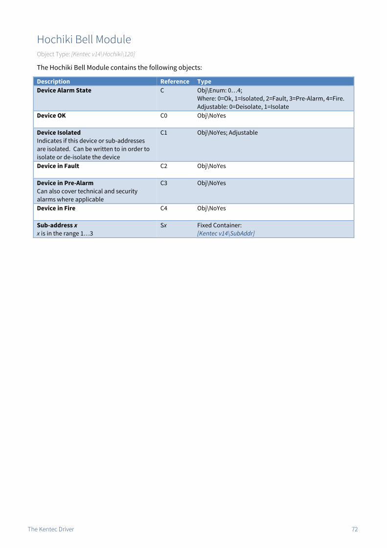
Hochiki Bell Module Object Type: [Kentec v14\Hochiki\120]
The Hochiki Bell Module contains the following objects:
Description Reference TypeDevice Alarm State C Obj\Enum: 0…4;
Where: 0=Ok, 1=Isolated, 2=Fault, 3=Pre-Alarm, 4=Fire. Adjustable: 0=Deisolate, 1=Isolate
Device OK
C0 Obj\NoYes
Device Isolated Indicates if this device or sub-addresses are isolated. Can be written to in order to isolate or de-isolate the device
C1 Obj\NoYes; Adjustable
Device in Fault
C2 Obj\NoYes
Device in Pre-Alarm Can also cover technical and security alarms where applicable
C3 Obj\NoYes
Device in Fire
C4 Obj\NoYes
Sub-address x x is in the range 1…3
Sx Fixed Container:[Kentec v14\SubAddr]

The Kentec Driver 73
Hochiki Multi IO Unit Object Type: [Kentec v14\Hochiki\122]
The Hochiki Multi IO Unit contains the following objects:
Description Reference TypeDevice Alarm State C Obj\Enum: 0…4;
Where: 0=Ok, 1=Isolated, 2=Fault, 3=Pre-Alarm, 4=Fire. Adjustable: 0=Deisolate, 1=Isolate
Device OK
C0 Obj\NoYes
Device Isolated Indicates if this device or sub-addresses are isolated. Can be written to in order to isolate or de-isolate the device
C1 Obj\NoYes; Adjustable
Device in Fault
C2 Obj\NoYes
Device in Pre-Alarm Can also cover technical and security alarms where applicable
C3 Obj\NoYes
Device in Fire
C4 Obj\NoYes
Sub-address x x is in the range 1…8
Sx Fixed Container:[Kentec v14\SubAddr]

The Kentec Driver 74
Hochiki Output Module Object Type: [Kentec v14\Hochiki\124]
The Hochiki Output Module contains the following objects:
Description Reference TypeDevice Alarm State C Obj\Enum: 0…4;
Where: 0=Ok, 1=Isolated, 2=Fault, 3=Pre-Alarm, 4=Fire. Adjustable: 0=Deisolate, 1=Isolate
Device OK
C0 Obj\NoYes
Device Isolated Indicates if this device or sub-addresses are isolated. Can be written to in order to isolate or de-isolate the device
C1 Obj\NoYes; Adjustable
Device in Fault
C2 Obj\NoYes
Device in Pre-Alarm Can also cover technical and security alarms where applicable
C3 Obj\NoYes
Device in Fire
C4 Obj\NoYes
Sub-address x x is in the range 1…3
Sx Fixed Container:[Kentec v14\SubAddr]

The Kentec Driver 75
Hochiki Single IO Module Object Type: [Kentec v14\Hochiki\125]
The Hochiki Single IO Module contains the following objects:
Description Reference TypeDevice Alarm State C Obj\Enum: 0…4;
Where: 0=Ok, 1=Isolated, 2=Fault, 3=Pre-Alarm, 4=Fire. Adjustable: 0=Deisolate, 1=Isolate
Device OK
C0 Obj\NoYes
Device Isolated Indicates if this device or sub-addresses are isolated. Can be written to in order to isolate or de-isolate the device
C1 Obj\NoYes; Adjustable
Device in Fault
C2 Obj\NoYes
Device in Pre-Alarm Can also cover technical and security alarms where applicable
C3 Obj\NoYes
Device in Fire
C4 Obj\NoYes
Sub-address x x is in the range 1…2
Sx Fixed Container:[Kentec v14\SubAddr]

The Kentec Driver 76
Hochiki POM Output Module Object Type: [Kentec v14\Hochiki\126]
The Hochiki POM Module contains the following objects:
Description Reference TypeDevice Alarm State C Obj\Enum: 0…4;
Where: 0=Ok, 1=Isolated, 2=Fault, 3=Pre-Alarm, 4=Fire. Adjustable: 0=Deisolate, 1=Isolate
Device OK
C0 Obj\NoYes
Device Isolated Indicates if this device or sub-addresses are isolated. Can be written to in order to isolate or de-isolate the device
C1 Obj\NoYes; Adjustable
Device in Fault
C2 Obj\NoYes
Device in Pre-Alarm Can also cover technical and security alarms where applicable
C3 Obj\NoYes
Device in Fire
C4 Obj\NoYes
Sub-address x x is in the range 1…3
Sx Fixed Container:[Kentec v14\SubAddr]

The Kentec Driver 77
Hochiki Photoelectric Object Type: [Kentec v14\Hochiki\136]
The Hochiki Photoelectric Sensor contains the following objects:
Description Reference TypeDevice Alarm State C Obj\Enum: 0…4;
Where: 0=Ok, 1=Isolated, 2=Fault, 3=Pre-Alarm, 4=Fire. Adjustable: 0=Deisolate, 1=Isolate
Device OK
C0 Obj\NoYes
Device Isolated Indicates whether this device is isolated. Can be written to in order to isolate or de-isolate the device
C1 Obj\NoYes; Adjustable
Device in Fault
C2 Obj\NoYes
Device in Pre-Alarm Can also cover technical and security alarms where applicable
C3 Obj\NoYes
Device in Fire
C4 Obj\NoYes

The Kentec Driver 78
Hochiki Heat Sensor Object Type: [Kentec v14\Hochiki\152]
The Hochiki Heat Sensor contains the following objects:
Description Reference TypeDevice Alarm State C Obj\Enum: 0…4;
Where: 0=Ok, 1=Isolated, 2=Fault, 3=Pre-Alarm, 4=Fire. Adjustable: 0=Deisolate, 1=Isolate
Device OK
C0 Obj\NoYes
Device Isolated Indicates whether this device is isolated. Can be written to in order to isolate or de-isolate the device
C1 Obj\NoYes; Adjustable
Device in Fault
C2 Obj\NoYes
Device in Pre-Alarm Can also cover technical and security alarms where applicable
C3 Obj\NoYes
Device in Fire
C4 Obj\NoYes

The Kentec Driver 79
Hochiki Heat Sensor ACB Object Type: [Kentec v14\Hochiki\153]
The Hochiki Heat Sensor ACB contains the following objects:
Description Reference TypeDevice Alarm State C Obj\Enum: 0…4;
Where: 0=Ok, 1=Isolated, 2=Fault, 3=Pre-Alarm, 4=Fire. Adjustable: 0=Deisolate, 1=Isolate
Device OK
C0 Obj\NoYes
Device Isolated Indicates whether this device is isolated. Can be written to in order to isolate or de-isolate the device
C1 Obj\NoYes; Adjustable
Device in Fault
C2 Obj\NoYes
Device in Pre-Alarm Can also cover technical and security alarms where applicable
C3 Obj\NoYes
Device in Fire
C4 Obj\NoYes

The Kentec Driver 80
Hochiki Ionisation Unit Object Type: [Kentec v14\Hochiki\168]
The Hochiki Ionisation Unit contains the following objects:
Description Reference TypeDevice Alarm State C Obj\Enum: 0…4;
Where: 0=Ok, 1=Isolated, 2=Fault, 3=Pre-Alarm, 4=Fire. Adjustable: 0=Deisolate, 1=Isolate
Device OK
C0 Obj\NoYes
Device Isolated Indicates whether this device is isolated. Can be written to in order to isolate or de-isolate the device
C1 Obj\NoYes; Adjustable
Device in Fault
C2 Obj\NoYes
Device in Pre-Alarm Can also cover technical and security alarms where applicable
C3 Obj\NoYes
Device in Fire
C4 Obj\NoYes

The Kentec Driver 81
Hochiki Multi Sensor Object Type: [Kentec v14\Hochiki\216]
The Hochiki Multi Sensor contains the following objects:
Description Reference TypeDevice Alarm State C Obj\Enum: 0…4;
Where: 0=Ok, 1=Isolated, 2=Fault, 3=Pre-Alarm, 4=Fire. Adjustable: 0=Deisolate, 1=Isolate
Device OK
C0 Obj\NoYes
Device Isolated Indicates whether this device is isolated. Can be written to in order to isolate or de-isolate the device
C1 Obj\NoYes; Adjustable
Device in Fault
C2 Obj\NoYes
Device in Pre-Alarm Can also cover technical and security alarms where applicable
C3 Obj\NoYes
Device in Fire
C4 Obj\NoYes

The Kentec Driver 82
I/O Board Object Type: [Kentec v14\IOBoard]
An on-panel I/O board contains up to 16 input channels, referenced using the sub-address.
Description Reference TypeDevice Alarm State C Obj\Enum: 0…4;
Where: 0=Ok, 1=Isolated, 2=Fault, 3=Pre-Alarm, 4=Fire. Adjustable: 0=Deisolate, 1=Isolate
Device OK
C0 Obj\NoYes
Device Isolated Indicates if this device or sub-addresses are isolated. Can be written to in order to isolate or de-isolate the device
C1 Obj\NoYes; Adjustable
Device in Fault
C2 Obj\NoYes
Device in Pre-Alarm Can also cover technical and security alarms where applicable
C3 Obj\NoYes
Device in Fire
C4 Obj\NoYes
Sub-address x The sub-address or input channel number, x, is in the range 1…16
Sx Fixed Container:[Kentec v14\SubAddr]

The Kentec Driver 83
Sub-address Object Type: [Kentec v14\SubAddr]
A Kentec sub-address contains the following objects:
Description Reference TypeAlarm State C Obj\Enum: 0…4;
Where: 0=Ok, 1=Isolated, 2=Fault, 3=Pre-Alarm, 4=Fire. Adjustable: 0=Deisolate, 1=Isolate
Sub-address OK
C0 Obj\NoYes
Sub-address Isolated Indicates whether this sub-address is isolated. Can be written to in order to isolate or de-isolate
C1 Obj\NoYes; Adjustable
Sub-address in Fault
C2 Obj\NoYes
Sub-address in Pre-Alarm Can also cover technical and security alarms where applicable
C3 Obj\NoYes
Sub-address in Fire
C4 Obj\NoYes

The Kentec Driver 84
Driver Versions Version Build Date Details 1.0 16/6/2007 Driver released 1.1 9/10/2008 Added new state objects C, F1.2 1/7/2010 Implemented new protocol commands and register for events.
Now support device isolations Now support Input Activated events
1.2 13/2/2013 Improved initializationNow support loop offset panel configurations
1.3 17/2/2014 New driver object MA, to speed up initialization.Now support panel I/O boards
1.3 03/12/2014 Request device isolation from panel to provide updated status if zone is isolated.Improved detection of panel initializing after watchdog reset. Set TIME object to update panel current time. Read not available. Previously this object accessed occupancy last change timestamp.
1.4 22/02/2018 Added driver objects to filter events based on a panel range (replacing maximum address object). Added driver objects to filter events based on type --- ignore isolations, etc. Modified system .C objects to be adjustable setting isolation where applicable.
This document is subject to change without notice and does not represent any commitment by North Building Technologies Ltd.
ObSys and Commander are trademarks of North Building Technologies Ltd. All other trademarks are property of their respective owners.
© Copyright 2018 North Building Technologies Limited.
Author: GS Checked by: JF
Document issued 21/03/2018.
Next Steps… If you require help, contact support on 01273 694422 or visit www.northbt.com/support
North Building Technologies Ltd +44 (0) 1273 694422 [email protected] www.northbt.com