The Journal Radio · the comfort of the goose that lays the golden eggs that prompted S. N. Shure,...
56
MAY, 1932 IN THIS ISSUE CHICAGO AND RADIO IN MAY THE APPLICATION OF PERMEABILITY TUNING TO BROADCAST RECEIVERS By R. H. Langley RADIO DISSEMINATION OF THE NATIONAL STANDARD OF FREQUENCY By J. H. Dellinger and E. L. Hall FURTHER DESCRIPTION, AND CHARACTERISTICS OF THE WUNDERLICH RADIO TUBE By Frederick E. Terman LOUDSPEAKERS WITH INDEPENDENT CONTROL ADDED TO RADIO RECEIVERS By W. L. Parsons TWELFTH YEAR OF SERVICE The Journal of the Radio and Allied Industries www.americanradiohistory.com
Transcript of The Journal Radio · the comfort of the goose that lays the golden eggs that prompted S. N. Shure,...

MAY, 1932
IN THIS ISSUE
CHICAGO AND RADIO IN MAY
THE APPLICATION OF PERMEABILITY TUNING TO
BROADCAST RECEIVERS
By R. H. Langley
RADIO DISSEMINATION OF THE NATIONAL STANDARD OF FREQUENCY
By J. H. Dellinger and E. L. Hall
FURTHER DESCRIPTION, AND CHARACTERISTICS OF
THE WUNDERLICH RADIO TUBE
By Frederick E. Terman
LOUDSPEAKERS WITH INDEPENDENT CONTROL ADDED TO RADIO RECEIVERS
By W. L. Parsons
TWELFTH YEAR OF SERVICE The Journal of the Radio and Allied Industries
www.americanradiohistory.com

UNITARY STRUCTURE Note the extreme rigidity of these tubes. The Unitary Structure principle of inter- locking the elements main- tains the precise inter- relation of parts through interdependence. Each rugged element is securely clamped at the top and bot- tom and the complete as- sembly isasturdvunit- in- suring constant uniformity.
assures matched tubes . . . enduring unii'ormit . . . long- lived perl'ormnnre
Seldom have new products offered such a decided improvement over existing devices. The uniformity, per- formance and unique construction of Arcturus transmitting tubes establish a new basis for considering operation cost per hour.
The exclusive "unitary structure' principle employed in these tubes - the same as used in the well -known Arcturus Blue receiving tubes -as- sures unvarying uniformity even under most rigorous conditions. "Unitary structure" also insures matched tubes, so necessary for critical operation. These tubes are interchangeable with other makes whose last two digits are similar.
Write for technical data bulletins on the Arcturus Types E703 -A, E711, E711 -E, E745 (50 -watt tubes) and E766 and E772 (mercury vapor rectifiers).
Arcturus Radio Tube Co., Newark, N. J.
*IICTURU$ Qua/[ Y/lf-17/LfT/1_
%ruhtí`ti0 n y, G2eceiTrirg auL 9ndcr,,ttria,L 2Liel.
www.americanradiohistory.com

MAY, 1932 Page I
IT BETT MAKE MORE
QUICKLY
INEXPENSIVELY
D V R
Is distribution sound? Does the adver- tising hit the market? How about overhead? How about the product itself?
Any radio manufacturer at this conven- tion who asks himself these questions must come, sooner or later, to a consid- eration of the materials he uses. Which explains in part, at least, why Durez is being put to hun- dreds of new uses -not only in the radio industry, but in almost every other line of business!
A better product, at low cost
Durez frequently enables a manu- facturer to make his product better, more quickly, and at less cost than he has made it before. A powdery, dust -like substance, Durez molds
under terrific pressure to take almost any required shape, pattern or design.
That finished product is tough, hard, durable. It needs no laborious finishing or polishing. It seldom chips or cracks. It has
high tensile and dielectric strength. Its surface is naturally as smooth and beautiful as burnished ebony. Studs and inserts can be imbedded in the one molding operation. In- tricate designs, trade -marks, insig- nias are accurately reproduced.
People who "do it with Durez" The list of Durez users in the radio and electric fields alone reads like a Who's Who of business. Stewart Warner, Delco, Turner Timer, Wagner Motor, Ford,
Westinghouse, Telechron, USL Battery -these are only a handful of hun- dreds of nationally known concerns who find Durez ideally suited to their needs. Remler Radio products, shown in the illus- tration, show how versatile this perfect molding compound really is.
This is a good time to check up on the way Durez fits into the plan of progressive manufacturers. Write now for free book- let. General Plastics, Inc., qq Walck Rd., N. Tonawanda, N. Y. Also New York, Chicago, San Francisco, Los Angeles.
UREZ THE PERFECT MOLDING COMPOUND
www.americanradiohistory.com

RADIO LiNGINJEE_RINS
Western Editor ULMER G. TURNER DONALD MCNICOL
MEMBER
UDIT
UREAU OP
IRCULATII
Editor Managing Editor F. WALEN
Vol. XII MAY, 1932 Number 5
EDITORIAL
Contents PAGE
4
A CHRONOLOGICAL HISTORY OF ELECTRICAL COM- MUNICATION- TELEGRAPH. TELEPHONE AND RADIO 6
CHICAGO AND RADIO IN MAY 13
RADIO TEST METHODS AND EQUIPMENT - By William F. Diehl 15
SOURCES OF LIGHT FOR TELEVISION .. By A. Ernest Lyle 16
THE APPLICATION OF PERMEABILITY TUNING TO
BROADCAST RECEIVERS By R. H. Langley 17
RADIO DISSEMINATION OF THE NATIONAL STANDARD
OF FREQUENCY ... By J. H. Dellinger and E. L. Hall 23
FURTHER DESCRIPTION, AND CHARACTERISTICS OF THE
WUNDERLICH RADIO TUBE .. By Frederick E. Terman 25
LOUDSPEAKERS WITH INDEPENDENT CONTROL ADDED
TO RADIO RECEIVERS By W. L. Parsons.. 29
FREQUENCY CONTROL MONITOR FOR BROADCAST STATIONS 30
PROGRESS IN RADIO TUBES 31
Departments NEWS OF THE INDUSTRY
NEW DEVELOPMENTS OF THE MONTH . .
INDEX TO ADVERTISERS
34
38
50
J
HELP FOR BROADCAST STATIONS
IT WAS not only kindly consideration for
the comfort of the goose that lays the golden
eggs that prompted S. N. Shure, of Shure
Brothers, Chicago, to launch a drive in the
interest of radio advertised products. Mr. Shure
has recognized the relationship between suc-
cess for broadcast stations and success for everyone engaged in radio manufacturing.
The idea is that if every person directly or indirectly earning his and her living from
radio sources would upon occasion sound the
tocsin for and purchase products the manufac-
turers of which sponsor and pay for radio pro-
grams, there would follow a buying response
that would rebound to the advantage of radio.
Gains in sales by radio advertisers would
strengthen the positions of broadcast stations
supported by advertising revenue.
Here is a contribution to the radio industry
which can be made by thousands of men and
women without increasing individual or family
expenses. It costs no more to purchase radio
advertised products than products advertised
by mailed circulars or other means.
BRYAN S. DAVIS President
JAS. A. WALKER Secretary
Published Monthly by
Bryan Davis Publishing Co.,
19 East 47th Street
New York City Chicago Office -333 N. Michigan Ave. -Charles H. Farrell, Mgr. St. Louis Office -505 Star Building -F. J. Wright OOP. t Kansas City Office-306 Coca Cola Building -L W. Mitchell San Francisco Office-155 Sansome St. -R. J. Birch
Entered as second class matter August 26, 1931, at the Post Office at New York, N. Y. under Act of March 3, 1879. Yearly subscription rate $2.00 in United States. Ií.00 m Canada
and foreign countries.
Inc. SANFORD R. COWAN Advertising Manager
J. E. NIELSEN Circulation Manager
Los Angeles Office-846 S. Broadway -R. J. Birch New Zealand -Tearo Book Depot -Wellington. Melbourne, Australia -McGill's Agency.
2
www.americanradiohistory.com

a
MAY, 1932 Page 3
TAKING THE BRAKES OFF THE AUDIO SYSTEM
DUE principally to the increase in power of broadcasting transmitters, radio en-
gineers since 1927 have concentrated their attention on the radio -frequency system of the radio set.
Now, with the introduction of the type 46 Dual -Grid Power -Output Amplifier and its companion, the type 82 Mercury -Vapor Rectifier, set designers can "open up" on the audio system and provide a strong, new appeal to the set buyer in the form of grati- fyingly greater realism.
The large reserve power available through the use of the 46 and 82 is an efficient pre- ventative of "blasting ", rattling, and dis- tortion- bugaboos of sets whose power tubes were subject to overload. While the maxi -
RCA RADIOTRON CO.,
mum available power may seldom be needed, the fact that it is available will make for better all -round performance. An 8- cylinder engine provides more horsepower than a light car ordinarily needs, but the car's average performance is better for the fact that such power is in reserve.
It should be borne in mind that even a barely perceptible increase in volume re- quires a very large increase in power sup- plied to the loud speaker.
Radiotrons 46 and 82, together with companion types 56, 57, and 58 of the new Super- phonic Series, enable set manufacturers to "step on the gas" with strikingly new receiv- ers having an instantaneous attrciction for the buying public.
INC. HARRISON, N. J. A Radio Corporation of America Subsidiary
RCA Radiotrons THE HEART OF YOUR RADIO
www.americanradiohistory.com

Editorial IIUIIIIWIIIIIIIIII I I 1IIIII1fUl111111CIP111111 II III411111MJ, II II I .I ..i. IIiIIIbiI.Illlllllll Illlllllllllülllill,Llülllllillllllllllllll
MAY, 1932
AT Ottawa, Canada, a par - BROADCASTING liamentary committee
has been holding hearings with the hope of bringing to
the surface constructive ideas which might guide the government in formulating a national radio broadcasting policy.
The makeup of the Canadian House of Com- mons possibly includes some few members whose habits of thought have made it natural for them to lean toward paternalism in govern- ment. Fortunately, the majority of the mem- bers, of both political faiths, is made up of men who have learned that what the government engages to pay out in expense must be collected from the taxpayers.
At one of these hearings a representative of the All- Canadian Congress of Labor is said to have advocated the establishment of a pow- erful chain of broadcasting stations by the gov- ernment.
If we may judge by the sanity exercised by Canadian legislators in handling liquor control, whereby millions of dollars are saved the tax- payers annually, and at the same time law ob- servance is maintained, it seems unlikely that the parliament will saddle the entire cost of broadcast stations directly upon the taxpayers.
The entering wedge of government owner- ship of broadcast stations would no doubt open the way for government ownership of automo- bile factories and harvesting machinery estab- lishments, and so on toward Communism.
If this should come to pass it would not be difficult to imagine certain of the pioneers who started Canada toward nationhood becoming restless in their graves.
IN CANADA
DR. KENNELLY RECEIVES INSTITUTE PRIZE
. AT the Pittsburgh conven-
tion of the Institute of Radio Engineers, in April, Dr. A. E. Kennelly, of Har-
vard University, was awarded the Institute's Gold Medal, which each year goes to an engi- neer who has contributed largely to radio science.
The first book on the subject of wireless telegraphy was published in 1898. The seventh book, written by Dr. Kennelly, was published in 1906. This work was sent forth
4
to the students of that early day as "a simple treatise," and yet it was perhaps the first sound treatment of electromagnetic radiation.
In the intervening twenty -six years Dr. Ken- nelly has made many contributions of a mathe- matical nature which enabled other engineers to explore and to unfold. Dr. Kennelly was the first to advance a logical explanation of the mechanism of wave transmission over dis- tances which involved the curvature of the earth. His announcement on this subject, dated March 15, 1902 (three months after Marconi's first trans -Atlantic tests) suggested the action of an upper reflecting layer in furthering the progress of waves sent out from a signaling station. This announcement preceded by three months the independent observation made by Oliver Heaviside, which carried the sanie sig- nificance.
The award of the Institute's gold medal to Dr. Kennelly will have the approval of engi- neers and physicists all over the world who have benefited from his writings and his teach- ing.
I T is illuminating to read FREE the recorded arguments RADIO of those who criticize the
present means of support for radio broadcast programs. For years past tax- payers have, ostrich like, allowed themselves to be "kidded" bankrupt by those who dealt in free education, free libraries, free concerts, free art galleries, free highways, etc. What an awakening there is in this year 1932 when tax- payers throughout the land have for the first time in decades time to analyze what the tax bill covers!
It is an old saw that "critics never have to make good." If anyone can work out a scheme of financial support for present day broadcast- ing, other than that now practiced, which will not mean added governmental expense and con- sequent added taxation, there is a present op- portunity for him to become world famous.
0&,ajc_/ ijlMCat Editor
www.americanradiohistory.com

MAY, 1932 Page 5
S eli-tapping Screw economies
da not depend on volume production
AMPLEX
BALDER GRAY
PHILMORE
PIERCE AIRO
TELERADIO
HALSON TROY
Unit Savings are the same for one or a thousand sets
To obtain the substantial assembly economies and other advantages which Self- tapping Screws bring to radio manu-
facture, it is not necessary to have a volume production like that of Philco, Zenith, Stromberg- Carlson, Crosley and otherlargeconcerns.The percentage of economy on a single unit per day is the same as on a thousand sets per day.
Listed in the illustration above are eight of the many
radio manufacturers with comparatively small production volume who make better and cheaper assemblies with
these unique Screws. Philmore Radio, for instance, states: - "Adoption of Self- tapping Screws for fastening units
Type "Z" Hardened Self- tapping Sheet Metal Screws For joining and making fastenings to sheet metal up to six gauge; also aluminum, die castings, Bakelite, etc. Simply turn Screw into drilled, pierced or molded hole. It formsa thread in the material as it is turned in. Can be removed and replaced.
and dial panels to chassis, speeded -up our production and reduced costs by eliminating tapping and unhandy
nuts and bolts. Also the Screws made possible an im-
provement in design" Offering all those advantages, Self- tapping Screws also make stronger fastenings - fastenings that do not jar loose in transit.
No special equipment or skill required You need no special equipment or skill to use Self- tapping Screws. Find out what they will save you. Our Assembly
Engineers will tell you, if you attach a description of one
or more assemblies when you mail the coupon below.
Type "U" Hardened Metallic Drive Screws
This type of Self- tapping Screw is used for making perma- nent fastenings to iron, brass and aluminum castings, steel, Bakelite, Durez, etc. Just hammer the Screw into a drilled or molded hole. It forms a thread In the material as it is driven
PARKE R-KALON cHardened Self-tapping Screws
N.a.. ia.;.....1 .M L. «...P...
PAT. IN U. 5. AND FOREIGN COUNTRIES
- - Application to well known radios. Scientists Explain Fastening Security - >
PARKER -KALON CORPORATION, Dept. L, 190 -198 Varick Street, New York, N. Y.
Send free booklets on Security and Uses of Self- tapping Screws in radio assemblies.
Tell me whether I can successfully use them for fastenings described on attached sheet.
Name and Company -
Address-
www.americanradiohistory.com

Page 6 RADIO ENGINEERING
A chronological history of electrical communication
-telegraph, telephone and radio
This history was begun in the January, 1932, issue of RADIO ENGINEERING, and will be continued in successive monthly issues through- out the year. The history is authoritative and will record all important dates, discoveries, in- ventions, necrology and statistics, with numer- ous contemporary chronological tie -in references to events in associated scientific developments. The entries will be carried along to our times.
Part V 1850 (189) A submarine telegraph line is laid across the
English channel, but due to failing insulation was operated only a short time.
(190) During this year considerable improvement is made in telegraph line construction methods. The House lines built between New York and Buffalo and between Buffalo and Cincinnati are the most sub- stantial lines thus far built.
(191) Judge Samuel L. Selden, of Rochester, N. Y., secures the agency for the extension of House sys- tem lines throughout the United States.
(192) Charles T. Chester, in America, develops a stand- ard telegraph battery, employing dilute sulphuric acid only.
(193) A Bain telegraph line is built by Henry D. Rogers between New York and Washington, the main office at 29 Wall St., New York. A New York and Boston Bain line, called the Merchants Line opened under the presidency of Marshall Lefferts.
(194) Anson Stager employs a common battery to feed a number of individual telegraph circuits. Previ- ously each line had its own battery.
(195) W. M. Swain elected president of the Magnetic Telegraph Company, operating the line between New York and Washington. (Remained president until 1858.)
(196) Prof. Nollet, of Brussels, Belgium, plans large magneto machines for electric lighting purposes.
(197) Bakewell, of London, invents a facsimile hand- writing telegraph.
(198) C. S. Bulkley, in America, invents an automatic telegraph repeater.
(199) William Sturgeon dies. (Born in England 1783.) 1851 (200) After the failure of previous attempts to maintain
cables, and aerial wires across the Hudson river, Simeon Borden, civil engineer, erects a pole -sup- ported line between Washington Heights, N. Y., and the Palisades, N. J., for the Magnetic Tele- graph Company.
(201) Dumont, in England, procures a patent (February) for a central office telegraph switching system.
(202) Farrar, in England, writes: "If current power could be varied by some slight variation of a vibrator, to be affected by the atmosphere as the tympanus of the ear is, the supposition is that the sounds of the voice might be reproduced."
(203) Henry S. Potter elected president of the New York and Mississippi Valley Printing Telegraph
,Company (April 2), the immediate predecessor of the Western Union Telegraph Company. Mr. Potter was the first president of the Western Union Company, holding that position until July 30, 1856.
(204) Hans Christian Oersted dies. (Born Denmark, 1777.)
(205) Aurora borealis electrical disturbances interfere with telegraph line operation throughout the New England states.
(200) Heinrich Rubinkorff, in Germany, constructs his first induction coil.
(207) During this year there were over fifty different telegraph companies doing business in the United States.
(208) The telegraph is first used for train -order move- ment of railway trains (on the Erie Railroad).
(209) A Bain telegraph line is constructed between New York and Buffalo by Henry V. O'Reilly. Mar- shall Lefferts served as president of the company. This line was extended also between Portland, Maine and Boston, Mass., and between Boston and Montreal. John W. Wilkins, an English tele- graph electrician, inventor of a sensitive relay, is engaged by O'Reilly.
(210) A cable containing four copper wires, insulated gutta -percha and surrounded by tarred hemp and protectéd by ten galvanized iron wires wound spirally about it, laid across the English Channel by a company of British and French capitalists. Opened for service on November 13. The cable weighed seven tons to the mile and was twenty - five miles long. This, the first successful subma- rine cable, remained in service many years.
1852 (211) Farmer and Channing apply the telegraph to fire - alarm signaling purposes in Boston, Mass.
(212) Aurora borealis disturbances (February 19) inter- fere with telegraph line operation in the North- eastern states. -
(213) Latimer Clark, in England, confirms theories pre- viously suggested by Ronalds and Faraday in regard to retardation of signals in long cables, as a result of electrostatic capacity.
(214) Referring to the proposal to connect Europe and America by telegraph cable, Alexander Jones, in his book on "The Electric Telegraph," published in New York, this year, says on page 6: "All idea of connecting Europe with America by lines di- rectly extending across the Atlantic is utterly impracticable and absurd."
1853 (215) Moses G. Farmer, of Framington, Mass., experi- ments with a system of duplex telegraphy.
(216) Professor Buff, of the University of Giessen, pub- lishes a paper dealing with the electrical proper- ties of flames. He concludes that gaseous bodies which have been rendered conductive by heating are capable of exciting other conductors, solid as well as gaseous, electrically. Insulated electrodes of platinum were inclosed in a glass container and the exterior of the container subjected to the heat of a spirit lamp. When the heat was most intense an exterior battery circuit connected to the elec- trodes, through a galvanometer, indicated the passage of current.
(217) Arago dies. (Born in France, 1786.) (218) Gintl, of Vienna, Austria; also Siemens and Halske,
in Germany, bring out systems of duplex telegra- phy. Neither of these systems was successful on long lines.
(219) The first telegraph convention is held, in Wash- ington, D. C. (March 5).
(220) The House telegraph system is placed in operation on 1,200 miles of line in Cuba.
(221) The Erie Railroad Company has 497 miles of tele- graph line in operation, with fifty -two offices. Sixty -five telegraph operators are employed by the company.
(222) During the year six submarine cables are laid, connecting England with Ireland, Scotland and the Continent. The longest cable laid is 100 nauti- cal miles in length. The cable between England and Ireland has six conductors.
(To be continued)
www.americanradiohistory.com

MAY, 1932 Page 7
V "RADIO HEADQUARTERS"
Broadcast Station IVEAF -50 kilouvatt,
Transmitting Radiotrons
that surpass even RCA Victor's previous high standards
At this time we especially invite the profes- sion to inspect the new Transmitting Radio- trons. These new tubes have established feats of performance of which RCA Victor has good cause to be proud.
The new Transmitting Radiotrons are products that the technical man might ex- pect to come from radio's foremost engi- neering organization.
TRANSMITTING RADIOTRON SALES ENGINEERING PRODUCTS DIVISION
RCA Victor Co., Inc. A Radio Corporation of America Subsidiary
Camden, N. J.
www.americanradiohistory.com

Page 8
\ panel mounting
fur panel mounting
No. 20 Series, with switch
No. 70 Series, with switch
No. 80 Series Single Unit, with switch
RADIO ENGINEERING
Announcing No.11 the new, long- lived, low- contact resistance snap switch with positive kick -off ..
OF primary interest to set manufacturers is the announcement of our new snap
switch. This is now available in two forms, No. 11, a separate S. P. S. T. switch for panel mounting, or Type "T," in combination with our complete line of positive- wiping- contact volume controls.
In either type this new switch has an ex- tremely low and a remarkably uniform con- tact resistance. It possesses exceptionally long life, as proved by our extensive breakdown tests. Because of its positive kick -off the open- ing or closing of the circuit is doubly assured.
The operating torque of No. 11 is the lowest of any commercial switch now offered the set manufacturer. In addition to its low torque this new switch operates with the smallest knob movement of any switch on the market, making available the maximum length of resistance element for controlling volume or tone.
Other features of this switch that you will be quick to appreciate are its "cold" cam, which is double bearing and cannot bind or wabble in operation; the wide separation of all live parts from the cam; electrostatic shield, that effectively prevents hum pickup by the volume control from live parts of the switch; heavy silver -plated terminals, insuring low contact resistance and ease of soldering; and approval by Underwriters' Laboratories for 3 A, 125 v., 1.5 A, 250 v., ac. or dc. We can supply these switches with or without leads.
We invite inquiries from interested manufacturers regarding this new switch, either for panel mount- ing or in association with our complete line of wire wound or carbon element volume and tone controls. Write us fully regarding your needs and allow us to submit samples made to your specifications.
No. 80 Series Single Unit, without switch
No. SO Series, Type H, with switch
No. 2 -80 Series lauden Unit, without switch
CHICAGO TELEPHONE SUPPLY CO. HERBERT H. FROST, Inc. e SALES DIVISION
ELKHART, INDIANA
www.americanradiohistory.com

THE FUTURE OF A
GIANT INDUSTRY As the towering heights of Radio City become a reality they will foreshadow the radio industry of the future.
To the public this project will symbolize a great ir- dustry. To the radio engineer it will symbolize a new era built around the electronic theory.
The part that copper plays in this development cannot be over-emphasized.
Among the most vital components of every radio system . broadcasting, receiving, television or communication ... are the wires that conduct and the coils which transform the electrical energy.
Inca magnet wire and coils have demonstrated in many critical applications their fitness for radio's most exacting needs.
QA MANUFACTURING DIVISION of Phelps Dodge Copper Products Corp., Fort Wayne, Ind.
Eastern Office: Western Office: 40 Wall St., New York. N. Y. 2375 E. 27th Sc., Los Angeles, fylif.
www.americanradiohistory.com

Assured Performance
The Type 60 Frequency Monitor em- braces features not found in any simi- lar unit. Exhaustive tests have shown conclusively that its performance greatly exceeds the requirements of General Order 116.
Precision Maximum frequency error is the drift over one week. Monitor may be checked against Station WWV (Bureau of Standards, Washington, D. C.) and, if necessary, easily corrected.
Universal The International Type 60 Unit, with- out change, will check ANY U. S. fre- quency.
Accuracy Frequency adherence, plus or minus 5 cycles at 1,000 kc. Frequency variation from one cycle in ten seconds to 100 cycles per second may be observed.
Stability The quartz crystal is clamped, thus eliminating frequency changes due to vibration.
A. C. Operated Immediate Delivery
e 1
A
0
Type 60 Universal Frequency Monitor with
Type lob Frequency dieter
F$'rite for Bulletin 17, which contains price list, and describes this apparatus
in detail.
3jnlrruattunal 1ruabraMltng i,Equtpmfitl Chu.
3112 West 51st St. Chicago, Illinois
www.americanradiohistory.com

MAY, 1932 Page I I
EVERY day more manufacturers are realizing the fact that
faulty lock washers are the great- est cause of poor performance. They have found out that loose connections hinder sales- increase serv- ice costs and discourage valuable cus- tomer good will.
That's why Shakeproof is winning its place on a steadily increasing number of products. This positive locking principle defeats vibration because its twisted teeth bite into both the nut and work surface, forming a solid contact and an absolutely
U. S. Patente 1.419,564 1,601.122 1.691,954 1,782,261
Othent. pener diicna
Foreign Patents.
tight lock. In fact, as vibration increases the teeth bite in deeper and only applied force can release their hold.
Take advantage of this profit saving lock washer and give your product the pro- tection it deserves. You can prove the worth of Shakeproof by a trial in your own shop. Free testing samples will be gladly sent on request -mail coupontoday.
SHAKEPROOF LocF¿,WasherCompany
(Division of Illinois Tool Works) 2509 North Keeler Avenue, Chicago, Illinois
Type 12. Internal For Type 11. External Type 15. Countersunk
S. A. E. and Standard For Standard Bolts For all Countersunk Machine Screws and Nuts Screws
Type 20 Locking Terminals
For Radio and Electrical Work
Shakeproof representatives are located in the following cities: New York City Philadelphia Boston Pittsburgh Schenectady Cleveland Detroit Toledo Cincinnati Birmingham, Ala. Dallas, Texas Milwaukee Los Angeles Seattle San Francisco Toronto, Ontario. Canada
"It's the Twisted Teeth that LOCK"
COUPON Gentlemen: We want to test your Shakeproof Lock Washers. Kindly send us samples as indicated.
Type _ Size
Type Size
Firm Name
Address
City State
By. Titk
www.americanradiohistory.com

Page 12 RADIO ENGINEERING
15 Textolite laminated parts were used in this timing device
OTHER PRODUCTS: Textolite molded Cetec cold -molded
EASTERN FABRICATOR
General Fabricating Co. 37 East 18th Street
New York City
WESTERN FABRICATOR
Electrical Insulating Corp. 308 Washington Street
Chicago, III,
F'.XTOLITE laminated, a. General Electric product, manu- I factured in sheets, tubes, and rods, was chosen for the fabrica-
tion of these parts because of its dependable uniformity, high dielectric and mechanical strength, and the ease with which it can be fabricated.
An increasing number of manufacturers in the electrical, radio, and electronic fields are using Textolite laminated -it assures positive, dependable operation of their products.
Investigate Textolite laminated. By adapting it to your product, you may be able to effect great savings for your company.
Ask for a copy of GEA -1458. Simply address General Electric Company, Plastics Department, Meriden, Conn.
831-15
GENERAL ELECTRIC
www.americanradiohistory.com
RADIO FMUINEERINU Production, Administration, Engineering, Servicing
MAY, 1932 , , , , , , , , , , , , , , , , , , , , , , , , , , . , , , , , , , , , , , , , , , , , , , , , , , , , , , , , , , , , , 1 , , , , , . , , , , , , , , , , , , , , , , , , , , , , , , , , , , , , , , , , , , n11111111111111111 , , , , . , , , , , , , m , , . , , , , , . , . , , , , , 1 , , , . 1111 , , , , , , , , , , , , , , , , , , , , , , , , , , , , , , , 1 , , , , , , , , , , , , , , , , 1 , , , , , , , , , , , , , , , , , , , , , . , , , , , , , , , , , , , 1 , , , , 1 , , , , , , , , 1 , , . , , , , , w , , .. , , , , , , , . , , , , , , , , 11111111111111111111111111111111111111111111 , , , , , , , , , , 1111111 , , , , , , , , , , , , , , , , , , , , . , , , , , , , , , , , , , , , , , , . , , , . , , , , , , ,
Chicago and radio in May
REASONS why every radio dealer and jobber should attend the eighth annual RMA convention and trade show at Chicago dur-
ing "radio week," beginning May 23, are detailed in a statement issued by President J. Clarke Coit of the RMA.
"No live radio distributor or dealer can afford to miss the annual RMA trade show in Chicago, May 23 -26," said President Coit. "Virtually every prominent manufacturer will display and to the trade only the newest radio and electrical products and lines for the forthcoming year. The contacts at this annual industry gathering are invalu- able to those who attend in Chicago. Never before were so many difficult and important problems pressing upon the industry. The problems of distribu- tion are especially complex and rapidly changing. The closest contacts with not only the newest radio and electrical
N. P. BLOOM Third Vice- President. RMA
products, but the newest and changing channels of distribution are essential. The opportunities of those who attend at Chicago during radio week are ob- vious.
"No individual who expects to profit in the selling, engineering or manufac- turing of radio can afford to miss be- ing present at Chicago during the week of May 23. Practically every one of any importance in these branches of the trade will be there during "radio week." The opportunity offered to view new merchandise, styles and trends, to become posted on manufacturing and technical developments, to make per- sonal contacts, to secure the opinion of all those vitally interested in radio is invaluable. At Chicago it will be pos- sible for an entire selling or buying organization to make business contacts, secure information and in a few days do what would otherwise take many months and at much greater expense.
"There will be a cordial welcome for everyone interested in radio at Chicago and the business contacts possible there. May 23 -26, are incalculable."
Final plans for the big annual radio gathering at Chicago and for vigorous opposition in the Senate against the proposed radio sales tax have been macle by the RMA board of directors. J. Clarke Coit, of Chicago, president of the Association, presided at the meeting at Hot Springs, Va., on April 8, which required special RMA cars for directors from the east and west. In addition to the industry gathering at Chicago in May and the sales tax. closer relations with jobbers and dealers, policies in connection with public radio shows, en- gineering developments and others, were considered. Nominations of new RMA officers to be elected at the May mem- bership meetings in Chicago were ap- proved by the Board. N. P. Bloom, of Louisville, Ky., third vice -president of the RMA, is chairman of the nomi- nating committee.
13
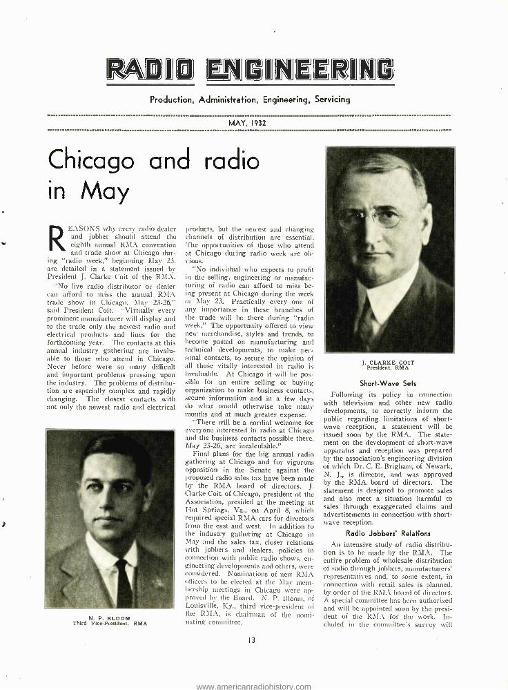
J. CLARKE COLT President. RMA
Short -Wave Sets
Following its policy in connection with television and other new radio developments, to correctly inform the public regarding limitations of short- wave reception, a statement will be issued soon by the RMA. The state- ment on the development of short -wave apparatus and reception was prepared by the association's engineering division of which Dr. C. E. Brigham, of Newark, N. J., is director, and was approved by the RMA board of directors. The statement is designed to promote sales and also meet a situation harmful to sales through exaggerated claims and advertisements in connection with short- wave reception.
Radio Jobbers' Relations
An intensive study of radio distribu- tion is to be made by the RMA. The entire problem of wholesale distribution of radio through jobbers, manufacturers' representatives and, to some extent, in connection with retail sales is planned, by order of the RMA board of directors. A special committee has been authorized and will be appointed soon by the presi- dent of the RMA for the work. In- cluded in the committee's survey will
www.americanradiohistory.com

Page 14
be the problem of trades organizations with the intent of the entire inquiry to increase cooperation between dis- tributors and manufacturers and the RMA.
Public Shows
The value of public radio shows to manufacturers will be considered by a special committee of the RMA to deter- mine the association's future policy in connection with public shows. For about two years the RMA refrained from sponsoring or endorsing any pub- lic shows or radio exhibitions other than its own well -established annual trade show, from which the public is excluded and to which only the trade is admitted. The committee to study the public show question, especially prob- lems relating to the New York and Chicago public shows held in past years, will be appointed soon.
School Promotion Manual
Manuscript and photographs for the manual being prepared by the RMA in cooperation with the U. S. Office of Education, Department of the Interior, to promote installations of radio and sound equipment in schools, have been assembled. The special RMA commit- tee engaged on the sales promotion project, headed by A. C. Kleckner, of Racine, Wisconsin, plans to complete and issue the manual late in May or soon thereafter. Many RMA manufac- turers of radio and sound apparatus have contributed valuable engineering assistance and data for inclusion in the school installation manual which is expected to develop wide equipment of schools and result in sales. The manual is especially designed to assist and ad- vise school authorities and others in
B. G. ERSKINE Chairman. Show Committee.
the use of radio in education and will be an authoritative and official manual for educators. The manual is to be distributed not only by the RMA and manufacturers, but also as an official document of the Government with the approval of the Office of Education, U. S. Department of the Interior.
E. V. HUGHES Director. RMA
Left: ARTHUR MOSS
Director. RMA
Right: W. I. BARKLEY
Director. RMA
RADIO ENGINEERING
Railroad Rate Reductions Sustained
Greatly reduced railroad rates on re- ceiving sets which were secured nearly two years ago by the RMA and attacked by interests of Omaha. Nebraska, have been sustained by the Interstate Com- merce Commission at Washington, ac- cording to advice to the RMA traffic bureau. The action of the Federal Commission dismissing complaints against the new rates is another im- portant victory for the RMA and its traffic bureau. The ruling permits the reduced rates on receiving sets to re- main in effect and they save set manu- facturers about ten per cent on ship- ments. A total saving last year was estimated at $ 1.500,000.
Automotive and Aeronautic Radio
To promote and stimulate automotive radio and cooperative engineering work in its development, the Society of Auto- motive Engineers has been invited by the RMA to form a joint committee for engineering studies in connection with automotive radio. The National Automobile Chamber of Commerce also has been consulted in the matter which was suggested by Dr. C. E. Brigham, chief of the RMA engineering division, and Virgil M. Graham, chairman of the RMA standards committee.
Work in the development of aero- nautic radio also has been done by the RMA liaison committee with the De- partment of Commerce organizations on aeronautic radio.
Radio Standards
Under the direction of Virgil M. Graham, of Rochester, N. Y., chairman of the RMA standards committee, many important standards for radio manufac-
www.americanradiohistory.com

MAY, 1932
ture have been considered at committee meetings and by letter ballot with re- sults distributed to RMA members. The RMA was invited to representation in the Acoustical Society of America and the appointment was accepted by Director Brigham of the engineering division. Much work also has been
done by the section committee on radio of the American Standards Association.
In addition to the important work of standardizing radio manufacture more effectually, service, safety and other problems have been considered by other engineering divisions. A meeting of the service section was held February
11 at New York by E. M. Hartley, of Camden, N. J., chairman.
Important standardizations on correct dial markings for short -wave, long - wave and all -wave receivers were made at a meeting of the engineering com- mittee on receivers March 24. A. Crossley, of South Haven, Mich., is
chairman of this committee, which also made standard recommendations for a
new six -pin tube socket to fit the new six -prong tubes recently released by tube manufacturers.
A meeting of the vacuum tube com- mittee, of which Roger M. Wise, of Emporium, Pa., is chairman, was held
Radio test methods and
THE paper deals with the test engineering division of the RCA- Victor Company, Inc., where radio activities of several manu-
facturing plants were centralized. The problems of this type of organization to control adequately the quality of, not only broadcast receivers and combina- tion instruments, but also sound equip- ment, direction finders, special receivers, and miscellaneous instruments are dis- cussed. Special emphasis is given to descriptions of the particular methods and apparatus used in this control of quality.
The quality control of manufactured products by inspection groups and test -' ing devices is not new to modern in- dustry. In the larger manufacturing plants, consideration has been given to the particular setup for handling this inspection, and the equipment employed and methods resorted to are frequently changed to meet the high standards re- quired by the industry.
Certain industries depend on visual inspection and simple mechanical checks. others on elaborate chemical analyses, and some on electrical measurements. in our plant, however, use is made of all such tests in the control of raw material, component parts, and the fin- ished product. By utilizing laboratory methods and equipment modified to meet production requirements, we are able today to effect accurate control in the factory to a higher degree than was even known to the laboratory in the earlier days.
The more exacting requirements de- manded of radio merchandise today, makes it impossible to resort to the old - fashioned method of simple listening
fA paper presented at the I. R. E. convention, Pittsburgh, Pa., April 8. 1932.
'RC.9 (Victor Company, Camden, N. J.
By \\ . i. F. DIEHL*
tests by skilled operators. Furthermore, it is important not only to know the performance of the product as shipped, but to have assurance that materials and component parts purchased from outside suppliers are according to specifications, which if met, will assure us that con- tinued service under various operating conditions will not materially affect this performance.
Equipment used in different labora- tories must be standardized and values used in the test specifications must be
determined by standard equipment from which secondary standards can be made; thereby, insuring consistent results.
The principal test equipment and
Page 15
April 6 at Pittsburgh during the spring convention of the Institute of Radio En- gineers. At Pittsburgh also the RMA standards committee on component parts, of which D. S. W. Kelly, of Mil- waukee, Wisc., is chairman, held a
meeting. Many of the new and valuable en-
gineering standards have been distrib- uted to RMA members by Chairman Graham of the standards and engineer- ing information section. Every effort is being made to maintain the RMA manual of standards and make it more useful and up - to - date for RMA members.
equipment t
methods of test which will be discussed and described, are as follows:
1. Chassis and final overall sensitiv- ity.
2. Hum. 3. Selectivity and i -f. alignment. 4. Continuity. 5. Method of checking gang capac-
itors. 6. Inductance of iron core reactors. 7. Test on electrolytic capacitors. 8. Filter capacitor life test equip-
ment. 9. Automatic power transformer test. 10. Hum analysis. 11. Flux density test on speakers. 12. Visual testing.
TEST ENGINEERING DIVISION
MATERIALS TEST AND APPROVAL
I LAB. APPROVAL Material and Ass'd Pt. Prior to Purchase from Outside Vendor A. Chemical Lab. B. Physical Lab. C. Elec. Lab. D. Life Test Lab.
2 LAB. CHECK Raw Material Ass'd Pt.
3 SPECIAL LAB. TEST
4 INSPECTION Raw material Assembled Pt. at Rec. Depot
5 INSPECTION Special Raw Material and Ass'd Part at Centralized Mfg. Point
TEST METHODS AND
EQUIPMENT
I PROD. TEST EQUIP.
A. Eng. Contact and Specification B. Dev. & Design
2 CALIBRATION AND MAINTE- NANCE
3 LAB. TUBE CHECKING
I I.AB. STANDARDS A. Dev. and De- sign I ab. Equip. B. Maintenance. Pri. Std. Meter Cal. and Repair C. Factory Std. D. Sr/eel Prob- lems.
QUALITY CONTROL
1 BROADCAST INSTRUMENTS A. Component Pts. B. Chassis Prelim. Tests
C. Final Tests
2 SOUND EQUIP- MENT
3 SPECIAL APPA- RATUS AND LAB. INSRUM EN TS
PRODUCT ANALYSIS
I DAILY SAMPLE CHECK A. Trends B. Consumer Reaction C. Defects D. Official Prod. and Shipping Re- lease
www.americanradiohistory.com

Page 16
Sources of light for television
By A. ERNEST LYLE*
LIGHT sources as utilized in tele- vision reception are of two main types, the first a "flat plate" lamp in which the glow discharge is
uniformly distributed over a cathode one or two inches square and the second a crater or "point source" lamp in which the glow, while greatly intensified, is restricted in size to a small area usually between 10 and 50 thousandths of an inch in diameter.
The "flat plate" type lamp finds its employment principally in conjunction with simple Nipkow scanning discs of the punched or drilled, hole type. Be- cause of the poor efficiency of such scan- ning systems, approximately only 1/4200 or less of the light available being viewed at any given instant, it is of ut- most importance that the lamp used in conjunction with such a disc be of as high an efficiency as is compatible with a reasonable life expectancy.
New Flat Plate Lamp
There has recently been developed a novel type of "flat plate" lamp having among its advantages an extremely high efficiency, a greatly improved frequency response, and an increased useful life.
This "wall electrode" television lamp achieves its high efficiency from the formation of an intense glow discharge by positive ion bombardment of a spe- cially treated, flat cathode. The glow is restricted to the front portion of the cathode in order that the entire energy applied to the tube may be utilized as useful light. Operating at 20 ma. the light output is in excess of 4 C.P.
Modern television, which, after all, is merely the resolving of a picture, and its recombination from numerous com- ponent parts, requires a wide frequency band. To obtain the detail which alone makes a television picture recognizable and comparable with other pictures, a band of from 30 to 50 kilocycles must be employed. During the early stages of development work it was found that the
'Chief Engineer, Cable Radio Tube Corpu.
Descriptions of modern type, flat plate and crater lamps for television uses.
average commercially available tele- vision lamp responded very poorly to the higher frequencies. This, seemingly, was due to the negative charge which accumulated during operation upon the glass envelope and acted as a third elec- trode-a negatively charged grid -tend- ing to increase the de- ionization time of the gas with the result that the lamp suf- fered greatly from frequency restric- tion, often failing to respond to most of the high frequency signal component.
From this study resulted the "wall electrode" type of television glow lamp in which the anode is in the form of a metallic coating on the inside of the lamp envelope itself. In this way the effect of the negative charge on the wall is avoided.
This type of construction offers other important advantages both from the standpoint of efficiency and increased life. During manufacture the metals vaporized to form the wall electrode, exerting a powerful getter action insur- ing an exceedingly pure gas content. Similarly, during life this large exposed getter area, continually activated by the gas discharge, greatly retards one ma- jor cause of tube failure -gas contami- nation -and thus increases the expected tube life.
The characteristics of the wall elec- trode television lamp are as follows :
Cathode surface 1 inch by 1 inch Ignition voltage 130- 140-v. d -c. Operating voltage 120 -150 -v. d -c. Maximum d -c. operating current....20 ma. Recommended d -c. operating cur-
rent 10 -15 ma. Ignition current (approx.) 5 ma. Extinguishing current (approx.) 2 ma. D -c. resistance at 20 ma. (ap-
prox.) 6,500 ohms Dynamic impedance at 20 ma. (ap-
prox.) 1,000 ohms A -c. power necessary for complete modu-
lation of light values at: 10 ma. operating current..... 35 milliwatts 20 ma. operating current.....175 milliwatts
The Crater Lamp e
Another widely employed television lamp is the so- called crater or point source type used generally in conjunc- tion with television projecting apparatus such as lens discs, mirror wheels and other optical scanning arrangements.
The requirements for a light source of the crater type differ considerably from those of the flat plate type. In the
RADIO ENGINEERING
crater lamp the light must be of an ex- tremely high intensity and restricted to a small area, generally within 0.0001 to 0.0025 square inch, in order that it may be sharply focussed as a tiny intense spot on the screen.
The gas discharge must be of a type susceptible to rapid modulation with- out undue lag and because of the amount of heat generated in a constricted space, special provisions for heat radiation must be incorporated.
Recently a crater lamp having these characteristics was developed and is now finding a wide application. This lamp is of a particularly rugged construction and has its light beam propagated in a direction parallel to the main tube axis. Its angle of radiation is extremely nar- row, in order that all generated light may be utilized, even with a small diam- eter lens. It is so designed mechanically that it may readily be employed with lenses of focal length as short as one - half inch.
Light Output
The intrinsic brilliancy is of a high order. A unique design and a specially developed coating process, incorporating the use of radio -active elements, not only assures improved performance and lowered ignition voltage, but also that a large percentage of the total radiation falls within the visible portion of the spectrum. The light output averages about 0.75 candle power per square mm. of light emitting surface.
The glow discharge in this crater lamp is concentrated in a small canal which compresses the Faraday dark space to an infinitesimal thickness and results in the discharge persisting in a semi -unstable condition, thus lending it- self well to modulation at high fre- quencies.
The operating impedance of gas dis- charge lamps of the crater type is ex- tremely low and as the frequency range to be accommodated is wide, extending to approximately 50 kc., the difficulty of obtaining an impedance match be- tween the output tube and the crater lamp is very great, so great, in fact, that it generally is not even attempted.
Thus the problem of crater lamp mod - ulation generally resolves itself simply into one of obtaining a sufficiently large peak current swing from the output tube. For complete modulation of light values the peak a -c. current must be of sufficient magnitude to approach the value of the d -c. operating current.
Particular study has been made to design a rugged tube electrically as well as mechanically. The crater lamp here described, while rated at 25 ma. d -c., operating current, will safely permit considerable overloads for short periods.
(Concluded on page 24)
www.americanradiohistory.com

MAY 1932 Page 17
The application of permeability tuning to broadcast receivers'
By R. H. LANGLEY*
THE chief difficulty with condenser tuning is that it is inherently in- capable of producing uniform per- formance. By the use of compound
couplings it is possible to secure reason- ably uniform gain, but no arrangement so far proposed will give uniform selec- tivity and fidelity except at the expense of a large decrease in the efficiency of each circuit. It was realized as early as 1922 that inductance tuning offered de- cided advantages in the solution of this problem.
Inductance tuning is a general term for any method in which the total effec- tive inductance in the circuit is varied. The variometer, which enjoyed a con- siderable vogue in 1922 -1924, was a de- vice for securing this variation. The reason it did not succeed was because its resistance varied with frequency in exactly the same way as the resistance of the fixed inductance of the condenser tuned systems, and it was therefore equally incapable of producing uniform performance.
There have been other suggestions for varying the inductance. One pro- posed to decrease the inductance by introducing a copper shield. The eddy currents in this shield effectively de- creased the inductance, but they simul- taneously increased the losses and, therefore, the effective resistance, at a rate even greater than in the variome- ter. Here again there was no possibility of securing uniform performance over the range.
The problem, however, is not to pro- duce a variation of inductance, but to produce a simultaneous and proportion- al variation of inductance and resistance. The recognition of this fact has come only recently. This is the result se- cured in the new tuning method which
tPresented before Radio Club of America, .!larch 9. 1932.
"Consulting Engineer.
Description of a new method of providing vari- able inductance tuning for
radio receivers.
we are examining tonight. It is called "permeability tuning" first to distinguish it from other methods of inductance variation, and second, because this term is adequately descriptive of its mechan- ism.
With permeability tuning. it is not only possible to secure uniform per- formance over the broadcast range, or any other range, on all three counts, with a degree of mechanical and electri- cal simplicity quite beyond anything so far suggested, but other new and valua- ble results can be secured.
It now becomes necessary to direct attention to a fact which has been too much neglected in the study of the problem of selectivity. The channels on which broadcasting, as well as all other radio services are carried out are equally spaced in frequency. The pub- lished mathematical investigations deal exclusively with per cent frequency dif- ference, which has no practical inter- pretation in terms of actual receiver performance. Even the current state- ment of selectivity in terms of band- width has no physical meaning as an indication of the signals that will be successfully rejected. What we desire to know is not the width of an inverted resonance curve, but just what signal strength, for signals on the channels immediately above and below resonance,
Fig. 1. Selectivity of five types of
radio receivers.
can be tolerated without producing audi- ble interference.
The situation with respect to selec- tivity can be summarized in a diagram, as is shown in Fig. 1.
This diagram represents the perform- ance of five different types of receivers. The horizontal scale in all four graphs is frequency, and the divisions are the actual channels of broadcasting. Graph A is for a tuned radio- frequency re- ceiver in which straight -line capacity condensers are used. The spacing of the channels on the dial of such a re- ceiver will be as shown, that is. very badly crowded toward the high fre- quency end. The black curves on this graph represent the apparent width, on the dial, of three signals of equal strength at three different frequencies. Note that, although the actual selectivity of the receiver is much worse at the high frequency end, the apparent selec- tivity is much better at the high fre- quency end. It shows how completely one fault masked another. It makes clear the fact that the straight line ca- pacity condenser, because it crowded the high frequency channels, completely covered up the glaring fault of the system in which it was used.
Let us now put straight- line -fre- quency condensers into this receiver. The channels will now be equally spaced on the dial, as in graph B, but the broad tuning at the high frequency end will be strikingly obvious, as indicated by the width of the band covered by the high frequency signal. Such a receiver would meet definite sales resistance be- cause of the lack of apparent selectivity, although the actual selectivity would be the sanie as in type A, thousands of which were successfully sold. Thus we see the reason the straight -line fre- ceiver condenser, otherwise an entirely logical and desirable improvement, was so slow to find its way into broadcast receivers.
If, by some method not yet suggested,
A° 700 800 000 .A3. 1100 1700 i I 1 1 1 1 I 1 1 1 1 II 1 I 1J 1111111111u111u11luuluyluululllu .
B,---- ,---- --'- lun 1lullllllnllllllllllllllullllhllllllul II11IIllllllllllllllllllllll Il lllllllullll ll
uuluuluuluulnnluulwllunluulun IIIIIIIIIIIIIIIIIIIIIIIIIIII
IIIn1111111111I111111n1I111IIIlI1IIII1111u111111u11II1uIlIllllllllnlllllllllllllllllllull 600 700 800 900 1000 1100 1200 1300 1400 13012
www.americanradiohistory.com

Page 18 RADIO ENGINEERING
.É =K Q'(K''L)` K ñ Q' R (L)
K.+ 4.*( a k"- 1i b(
k ir"
g w2R 4=2.73
R h L 7.43 R 7.43 (9)
=2.T3r
(2)
(3)
(4)
Fig. 2. Selectivity equations.
we could arrange so that the actual per cent selectivity, the selectivity of the mathematical treatments, were constant over the frequency range, we should have the situation shown in graph C. Still the apparent selectivity would be noticeably worse at the high frequency end, and so would be the actual selec- tivity, so far as ability to reject unde- sired signals is concerned.
Graph D may be taken as represent- ing a superheterodyne receiver, or a properly designed receiver of the per meability -tuned type. In either case the actual channel selectivity is constant over the range. In the superheterodyne, there would be some slight deviation, depending upon the amount of con- denser- tuned -radio- frequency amplifica- tion employed. In the permeability- tuned receiver there would be substan- tially no deviation, and, incidentally, it would not be necessary to employ spe- cial mechanical arrangements to secure the equal spacing of the channels on the dial. There can, of course, be no question that the performance of graph D is superior to A, B or C, and that it is the ideal result.
To understand why permeability tun- ing can accomplish this result, with less tubes and fewer tuned circuits than a superheterodyne, it is necessary to examine the mathematics of the situa- tion.
The usual expression for selectivity is given in equation (1), Fig. 2. This states the ratio of the voltages devel- oped across the tuned circuit by a reso- nant signal and a non -resonant signal, in terms of K which is the ratio of the two frequencies, and Q which is the ratio of the inductive reactance at reso- nance to the resistance. Q has been called the figure of merit of the circuit. Note that both K and Q vary with fre- quency.
In order to determine the conditions for constant selectivity, we use small letters to represent quantities at the low frequency end of the range, and large letters for the high frequency end, and we write equation (2) directly from equation (1). Upon simplification this yields equation (3) which gives, im-
plicitly, the ratio which the values of
Q, one at the low frequency end, and
one at the high frequency end, must have for constant selectivity.
Numerical substitution in equation (3) for the broadcast case, and for the actual 10 kc. separation for the broad- cast signals, justifies the writing of equation (4) with the assurance that it is correct, at least to a very close or- der of approximation. Equation (4) gives the important conclusion that for constant selectivity the ratio of induct- ance to resistance must remain constant.
In normal condenser tuned circuits, and in inductance tuned circuits of the variometer types, the resistance in- creases approximately as the square of the frequency. Thus Q (equals omega L over R) decreases as the frequency is increased. If R could be made di- rectly proportional to frequency, then Q would be constant, but even then the selectivity would not be constant, be- cause K, the ratio of the frequencies, is also changing. Selectivity, in terms of actual ability to reject signals on undesired channels, can only be con- stant over the range when the ratio of inductance to resistance does not change.
In condenser tuned circuits, the in- ductance is held constant and the re- sistance increases as the square of the frequency. Such a circuit, therefore, cannot have constant selectivity, except by the expedient of artificially increas- ing the resistance at the low frequency end. A good tuned circuit has a resist- ance of about 4 ohms at 550 kc. and 30 ohms at 1,500 kc. If we can con- trive to keep the resistance up to 30 ohms throughout the range, then we can have constant selectivity over the range, and it will be just as broad as 550 kc. as it now is at 1.500.
In inductance tuning, the inductance must change inversely as the square of the frequency. For constant selectivity, the resistance must also change in- versely as the square of the frequency. This is expressed in equation (5) which states that the resistance and the induct- ance are to be approximately eight times as large at the low frequency end of the range as they are at the high frequency end.
How can we design a variometer, for use in an inductance tuned circuit, such that the inductance and the resistance will increase together, and their ratio
Porcelain 2150 x 1012
Glass 990 x 1012
Bakelite 36 x 1012
Polydoroff iron 50 Carbon (filament) 004 Nichrome . 000 109 Steel 000 045 6 Iron (pure) 000 008 85 Copper 000 001 589
Fig. 3. Comparative resistivity in ohms per centimenter cube.
remain constant? By a very simple ex- pedient. We will design our circuit at the high frequency end, at 1,500 kc., to have whatever properties we desire to get, high gain and a high order of se- lectivity. We will use a relatively small inductance and a relatively large fixed condenser. Naturally both of these will have to he designed so as to have low losses.
Variable Inductance
We will then tune this combination down to 550 kc. by gradually inserting an iron core into the inductance. This will increase both its inductance and its resistance, and we may expect that they will increase together, since both depend upon the amount of iron which is actually inserted in the magnetic field. It will, of course, take a very special form of iron. No form that we have known in the past can be brought any- where near a tuned radio -frequency cir- cuit without increasing its apparent re- sistance out of all proportion to the gain in inductance.
Before we examine the material and the core, let us see what some of the other consequences of this method of tuning are going to be. We are not in- creasing the inductance of the coil it- self. What we are doing is to increase the permeability of the surrounding me- dium. We are actually inserting a new factor in the equation for the frequency of the system. This factor is the ef- fective permeability of the space around the coil. This is the reason for calling the system permeability tuning.
We should assume. from the nature of the method, that if we have two coils of different inductances, but of the same physical dimensions, and if we insert two identical cores into them, the per- centage change in inductance would be the same. If we tune these two coils, with different fixed condensers to the same frequency, then as the cores are inserted they should remain in step with each other.
This result can easily be secured, and it has tremendous consequences. It means that for the first time we have a method of tuning the antenna circuit of a broadcast receiver, and keeping it exactly aligned with the other tuned circuits. .It means that we can thus secure a gain ahead of the first grid, due to resonance in the antenna circuit, which gives a very noticeable and valu- able decrease in the amount of subse- quent amplification necessary. But the most important result, so far as the user is concerned, is the marked im- provement in the signal -to -noise ratio. This, more than any other feature of the performance of a permeability -tuned receiver, is its outstanding advantage over other present types.
www.americanradiohistory.com

MAY, 1932
Another result, not quite so obvious, perhaps, is that the frequency to which the system is tuned at any time is al- most exactly proportional to the dis- tance to which the core has been re- moved from the coil. By a slight cor- rection in the shape of the core the rela- tion may be made exact, and this gives, without additional mechanical gear, a uniform or "straight -line- frequency" distribution of the channels on the in- dicator. Thus the result so difficult to secure with condenser tuning is easily and naturally accomplished in the per- meability method.
Since the resistance and the induct- ance increase at the same rate, an os- cillator can be built in which the out- put is very nearly constant. And, by the use of a series inductance, not af- fected by the core, such an oscillator can be kept at any desired absolute frequency difference from other tuned circuits on the same uni- control system. Such an oscillator would have wide use- fulness in superheterodyne receivers.
If it is desired to build a receiver having two or three ranges, each as wide as the present broadcast range, this can be accomplished by using as many taps on the fixed condensers in each tuned circuit. These taps can be selected by a gang switch without ap- preciable increase in losses, and the ar- rangement is mechanically convenient and simple. The ranges in such a re- ceiver will not have quite the same per- formance, but the difference can be minimized by proper choice of the in- ductance and the capacity steps. Here, therefore, is a new and simple answer to the problem of an "all- wave" receiver for European service, or for any other service requiring an extremely wide range.
In a condenser tuned system there is a certain minimum capacity, represent- ed by the maximum spacing obtainable between the rotor and the stator, and by the various capacities which exist in the circuits. This minimum capacity determines the value of inductance to be used, since the two together must produce resonance at 1,500 kc. The maximum value of the condenser is thus also determined, since this value taken with the same value of inductance must tune to 550 kc.
With permeability tuning, there is no such limitation. The inductance may have any value desirable to produce the required performance. Whatever the value of the inductance may be, it will be increased approximately eight times by the insertion of the core. Whatever the resonant frequency of coil and con- denser may be, it will be decreased to approximately one -third this value, when the core goes into the coil. Thus we really have a new, an independent variable. It is not the inductance of
the coil itself that we are varying: it is the effective permeability of the me- dium surrounding the coil.
When the research to find a form of iron that could be successfully used at radio frequencies was first undertaken, it was appreciated that the task was no small one. In fact, quite a group of scientists had said that it could not be done, and this same statement was re- peated after the work was well under way. The core material that we have today is no chance discovery. It is the result of a carefully planned and ade- quately financed research.
Core Material
Iron sulphate is reduced by hydrogen to a metallic powder. The sulphate is rhombic in crystalline form, the iron cubic. In passing from rhombic to cubic the material must go through atomic or at least molecular dimensions. By proper control of the process it is pos- sible to obtain the powdered iron in any desired degree of fineness. Iron dust
Fig. 4
Characteristics curves.
1nnnnunuunnuummw,:c.mu
Page 19
so fine that it will float in the air can be produced. The particle size which has been chosen for this use is 10 microns, approximately 0.00039 inch. The powder is, of course, of very high purity.
Before this powder is allowed to come into contact with air, the individual par- ticles are insulated. This requires an entirely new insulator, especially devel- oped for the purpose. None of the ex- isting insulating materials was suited to the work. The film surrounding each particle is approximately one micron thick. This amount of insulation is ade- quate for the minute voltages gener- ated in the particles by the magnetic field. Current is therefore effectively prevented from flowing between parti- cles. The eddy current loss is therefore limited to the energy that can be dis- sipated within the particles, and this loss, in particles of the size mentioned, is low enough to permit successful use at the frequencies used in broadcasting.
This insulated iron powder is now molded with bakelite in much the same
P/E
.a6
.0/4
.o/
ooa
6
/00 ,e00 o00 .roo soo I
27eirceem rr](lloc.yeÌes. A 7
t25
Roo
/75
/50
/as
/00
7S
6o- AT
0
8
l-6 SnTnv,oídp! Cr.,(
t .4 . e Prr7eollc c
- Of /0 .Ì gTK, u ñen ry s
I / e ¿¡SrdP ft. coTO' \ 0
a y p ti
F c9 PZT
s G Ú 6 %
!ri,%/i'J,
,: .
;
; 4+. , ` ..56- , 1 . ,5"L.
R 8 .
* y
I
6, IE- --- , C h
I
Liggill 00 boo Boo /000 /z00 //00
Frepurncy in locyeles.
www.americanradiohistory.com

Page 20 RADIO ENGINEERING
7 s
ùilluillhINIVIIIIIUIÍI.
r4
way that any other dry powdered filler, such as wood flour, would be molded. The molds are made of steel, as usual. Any desired form that is capable of molding in any material can be molded in this new iron, but the usual forms are circular in section, and the molds are therefore simple and inexpensive.
This new molded magnetic material is 92% iron by weight. But the remain- ing 8 %, which is insulating material, so completely changes the electrical and magnetic behavior that it is really incor- rect to still call it iron. At present we are referring to it as "Polydoroff iron" or as "Polyiron" which has the advan- tage of suggesting the minute subdi- vision of the iron. Eventually we shall have to have an entirely new name.
Permeability, in general, is the ratio between a magnetizing force and the flux which it produces in the material under consideration. But when alternat- ing currents are involved, even at com- mercial frequencies, a more precise and complicated definition must be used. The presence of direct as well as alternating current still further complicates the mat- ter. There is an extensive literature on this subject alone. As we approach the frequencies used in radio, all the usual definitions and methods of measurement cease to have any rational meaning. We are left, therefore, with no alternative except to state the permeability of the new material in terms of its effect upon the inductance of an air -core radio fre- quency coil into which it is inserted. On this basis, the permeability of Poly - iron is about 8, which is adequate for the use we are describing, but I must caution that this figure is not to be compared with the direct current per- meability of commercial sheet steels.
Hysteresis loss in magnetic materials at commercial frequencies, is propor- tional to the area of the hysteresis loop, and increases with frequency. But as we approach the frequencies used in ra- dio, the area of the loop becomes dis- appearingly small, and the loss from this cause becomes negligible. What- ever effect the introduction of an iron core in a radio- frequency coil may have upon its effective resistance, is due, therefore, to the eddy- current loss. This loss may be reduced by shortening the paths which the induced currents can
ouummnnummmmuommnnon
Fig. 5. Overall dimensions of
tuning unit.
iinnuunino w m unw u unow m, 1u i
take, and by decreasing the resistance of these paths. This result is secured by lamination, which was carried to its practical limit in the one mil steel of the Alexanderson high frequency alter- nator. Beyond this, we may resort to powdered material, with the particles insulated, and this has been carried to the limit in Polyiron.
The extent to which the attempt to insulate the particles has been success- ful is indicated by the measured re- sistivity of the material. Here is per- haps the most unique property of Poly - iron. It measures 50 ohms per centi- meter cube, and, as you will see from the tabulation in Fig. 3, lies intermedi- ate between insulators and conductors. No known material, whether ferric or not, lies within several orders of mag- nitude of this value. Polyiron has over five million times the resistivity of or- dinary pure iron.
The losses in this new material are extremely low, but they increase with frequency. The core loss, in ergs. per cycle, increases at a rate somewhat be- low the second power of the frequency, as shown in the upper curve of Fig. 4. The effective radio -frequency resistance of the core, however, increases almost as the fourth power of the frequency. How, then, can we make the high fre- quency resistance of the complete tuned circuit decrease with frequency, as it must if the performance is to remain constant? To answer this, I have only to remind you that the core is with- drawn to increase the frequency, so that as the frequency is increased, there is less and less of the iron present in the field.
The tuned circuit consists of a coil, wound on the usual bakelite form, a Polyiron core arranged so that it can slide into the coil, and a fixed condenser, usually of mica, with an adjustable blade, to secure initial resonance. with the core all the way out, at 1,500 kc. The condenser is mounted on a suitable ceramic base, and the coil and condenser on its base are mounted inside a cylin- drical shield of aluminum or copper. The condenser is connected across the coil. There is no electrical connection to the core, but it is usually insulated from the grounded frame of the net, to prevent capacity effects. As shown
in Fig. 5, the overall dimensions of the complete tuned circuit, with the core all the way out, are only 2 inches diameter by 3YI inches long, a total volume of less than 12 cubic inches.
Note that there will be no leads to variable condensers at some distance. Also note that there is no primary on this coil, that it is not a transformer. There are only three leads from such a tuned circuit, one to a grid or plate, one to a B or C voltage supply, and one ground or to a coupling condenser. The circuit is therefore simple, and the shielding simple and inexpensive. The circuits may be placed as close together as desired, so long as the cans do not touch.
The internal member of the core is an easy fit inside the coil form. The inside diameter of the outside member of the core is made sufficiently large so that there is no possibility of its touch- ing the winding. The total movement of the core is 1% inches. The winding is preferably of Litzendraht. In the usual condenser -tuned circuit this wire does not have sufficient advantage to justify its use, but in the very much smaller inductances used in the per- meability -tuned system, the stranded conductor gives a worthwhile decrease in the resistance at 1,500 kc., the fre- quency for which the coil is designed. The preferred wire has 10 strands of No. 41, which is a size standard with the wire manufacturers.
In Fig. 6 is shown the first perme- ability -tuned receiver employing the new core material. It had three radio stages, and four tuned circuits, with detector, output tube and rectifier, six tubes in all. The tuned circuits were assembled as a unit, and mounted under the chassis pan in such a way that the coil terminals came directly under the socket terminals making the leads ex- tremely short. You will notice, at the bottom, the bridle which carries the four cores and the screws by which the positions of the cores were adjusted. This bridle slid back and forth on guide plates, one at either side, and was driven by a linkage at each end of a shaft run-
Fig. 6. First model of permeability tuned receiver.
www.americanradiohistory.com

MAY, 1932
PERMEABILITY TUNED 5 CIRCUIT 6 TUBE RECEIVER
ALTERNATE INTERSTAGE SELECTOR OSCILLATOR
ning across the back of the unit. The sensitivity of this receiver was better than 1 microvolt, and it would success- fully reject a signal 10 times as strong as the desired signal on the adjacent channels.
Practical Application
The development since this first re- ceiver was produced has been chiefly in two directions : first, to produce a more effective and less expensive mech- anism and, second, to determine the form of circuit best adapted to take full advantage of the unique properties of the new system and the high amplifying capabilities of the later screen grid tubes. As a result of this work, the lat- est chasses are quite different, both me- chanically and electrically, and they are correspondingly better in performance, lower in cost, and more completely adapted to quantity production in a mod- ern factory. Because of the inherent savings of space which result from the method, no attempt has been made to crowd the new designs into the small- est possible compass. There is, there- fore, ample room for easy wiring and assembly, and yet the complete chassis is smaller and lighter than any of the current condenser tuned chasses of equivalent performance.
The circuit development has led to the adoption of a condenser coupled ar- rangement with both plate and grid cir- cuits tuned, as is shown in Fig. 7. The antenna circuit, which directly feeds the grid of the first tube is also tuned so that we have five tuned' circuits, but only two radio- frequency amplifier tubes. The antenna circuit is made to
0vnnnoiumWwmimaHimiTH
Fig. 7. Condenser coupling of plate and grid circuits.
T11111
follow the other tuned circuits exactly by initial adjustment of the series an- tenna condenser and gives a gain on the first grid of from 18 to 22. The value of this preliminary tuning, before any amplification takes place, reducing the value' of interfering signals and induc- tive disturbances before they reach the first grid cannot be over- estimated. That this produces a marked improvement in performance is apparent the moment the receiver is tuned to the first'signal.
In all the tuned circuits the induct- ance value, measured without the core, is 65 microhenrys, and the capacitance is 160 mmfd., which is approximately three times the minimum capacitance, effective at 1,500 kc., in condenser tuned systems. The coupling condensers are .02 mfd. Other constants of the radio
Page 21
amplifier and the complete audio am- plifier are normal.
The symbol used here to indicate vari- able permeability has simplicity if noth- ing else to recommend it, and it has been found to be not easily confused with other features usual in radio dia- grams.
At the lower left is shown an alter- nate arrangement for the tuned circuits between the tubes which more nearly corresponds to the forms that have been used with condenser tuning, but, per- haps for that very reason, is not quite so constant in performance over the range. There is also shown, at the bottom right, the circuit for an oscillator, which will have very nearly constant output.
The five tuned circuits are assembled into a mechanical unit illustrated in Fig. 8 actually smaller than the usual five -gang condenser. The cores are mounted on a rigid bridle, actuated by a short rack and a cooperating pinion on the knob shaft. Any reasonable mo- tion reduction can thus be easily se- cured, and this without complicating the very simple indicator, which can be adapted to either "full- vision" or the more usual type of dial, and is auto- matically "straight -line- frequency."
In the view at the lower right, some of the shield cans have been removed to show the coils and cores, and the insulating bases that support the mica condensers. The three top wires, with clips, connect to the grids of the two radio tubes and the detector. the black wire to the antenna terminal, and the four remaining wires to the two plates, and to the B supply. The coils are mounted directly on the back plate, not on the porcelain, in such a way that they may be adjusted to give the initial correct position with respect to the cores which are rigidly mounted on the bridle.
Since both the inductance and the capacitance are capable of adjustment,
Fig. 8. Assembly of tuning units.
www.americanradiohistory.com

Page 22 RADIO ENGINEERING
tMr^r5i 7":eT41,.,1.;,
the inductance by the relative position of the core and coil, and the capacitance by the small adjustable leaf on the fixed condenser, the receiver is aligned after it has been completely assembled. There is no step equivalent to the necessity, in condenser -tuned systems, of aligning the gang unit before it is assembled on the set. The only source of variation is the moulded cores, and these are made in the same mould, under the same tem- perature and pressure, from a weighed quantity of material from a large and thoroughly mixed batch. Careful checks have shown that the degree of repro- ducibility is very high, and that the maximum error in a five gang unit will be less than one -half of one per cent. There is the further advantage that the maximum error occurs at 550 kc. where the stations have the greatest per cent separation. The method of alignment produces exact agreement at two points in the range. With the cores all the way out, the circuits are definitely tuned to a 1500 kc. signal, by adjustment of the condensers. The cores are then ad- vanced to a mid position, and exact re- sonance to a 1000 kc. signal is secured by adjustment of the position of the coils with respect to the cores.
The overall alignment is thus actually better than can be secured by the prior calibration of variable condensers and
i Iu I I II I I',' I I v! I! I A ll l l I I:I G. U I I I I I IIII
Fig. 9. Completed chassis.
' 9' I I191I A I I! I I I I I I II I I I I I I I I I I I III II II I
coils in the usual system, and nothing short of actual tinkering will change it after it has once been established. The effect of changes in temperature is nil, and there are no parts sufficiently deli- cate to be displaced due to jars received in shipment. Slight differences between the inductance values of the coils are of no consequence, provided the coils are geometrically alike, and this is secured by using moulded forms.
Another form of unit, shown at the center, Fig. 8, is directly adjusted by a screw passing through the bridle. This type may be more adaptable in some ap- plications. There is also shown, at the left, a three core unit intended for pos- sible use as a pretuner in superhetero- dynes.
In the completed chassis shown in Fig. 9, the units have been so arranged as to bring the three controls out at the center, so that adaptation to any cabinet design would be easy. Other ar- rangements, to suit particular cabinet designs can of course be made. Because there is no variable condenser gang, and because each tuned circuit is complete in itself, the wiring under the chassis pan is very much simplified. The re- ceiver shown is only an "engineering model" and still requires the attention of the factory or production engineers to eliminate those little difficulties of as-
sembly and wiring which make such a large difference in the speed of pro- duction and in the cost. Being almost completely hand made, it does not pre- sent the finished appearance of a factory product.
It is a matter of some difficulty to give anything amounting to an accurate cost comparison. The cores themselves will cost no more than the variable con- densers which they replace. Beyond this there are a number of direct and indirect savings. The coils, for example, have a very much smaller secondary winding, and no primary. Nor have they any compensating windings. They are smaller in diameter, and so are the shield cans. Thus the space now occu- pied by the variable condenser gang is completely saved, and the space required for the coils greatly reduced. The high frequency wiring is materially simplified and shortened. Since the tuning and coupling condensers are mounted inside the shield cans, which are magnetically closed by the cores, the shielding is also greatly simplified. Compared to the superheterodynes, the oscillator and its tuned circuit and coupling means are saved. Even if the cores had to be sold at a slight advance over the cost of the variable condenser sections, there would still be a considerable saving.
One factor deserves to be emphasized. Receivers built in accordance with the new method will be strikingly new and different, both in appearance and in per- formance. The dealer first, and the public later, will be conscious of this difference. And they will conclude that a worthwhile new contribution has been made to the art of radio reception. This is the factor which more than any other recommends permeability tuning to the sales managers and the executive heads of the industry.
To the inventor, Mr. Polydoroff, and to Mr. Victor S. Johnson, who sup- ported him, goes the credit for having successfully completed an important and courageous research addressed to the problem of radio reception.
New Canadian Station Ground was broken in April in Sandwich, Ontario for the transmitter house for radio station
CKWO, which will be the first radio station on the Ontario western side of the border and will start broadcasting May 31st. The towers, which will be 200 feet high and 500 feet apart, will be the highest in the Dominion.
The station will broadcast the best of Canadian programs, as well as features of international interest through its hookup with the Columbia Broadcasting System.
Studios will occupy the twelfth floor of the Guaranty Trust Building in Windsor, with sup- plementary studios in Detroit.
The Border Cities Star, one of the acknowledged leaders in Canadian newspaperdom, will use the station to broadcast news. The station is owned by Essex Broadcasters, Limited, the directors of which are: Malcolm G. Campbell, president of Kelsey Wheel Company; W. B. Perley, president of Canadian Steel Company; A. F. Healy, president, and C. W. McDiarmid, vice -president, The Guaranty Trust Company, and W. F. Morgan- Deane, retired industrialist.
www.americanradiohistory.com

MAY, 1932
Radio dissemination of the national standard of frequency'
By J. H. DELLINGER and E. L. HALL`
THE fundamental standard in radio communications is that of fre- quency. In order that the maxi- mum number of radio messages
or programs may be transmitted simul- taneously, it is necessary that the fre- quencies of the radio waves which carry them be maintained very accur- ately. If the frequency varies, the message or program will interfere with others carried on adjacent frequencies. Therefore accurately maintaining fre- quency is a basic requirement of all radio operation.
Means must be provided to insure that all stations operate accurately on the same frequency basis. Fortunately, the standard of frequency has the unique property that it can be made widely available by means of radio transmission. Radio waves of which the frequency is carefully controlled and accurately known furnish a standard of frequency which is simultaneously avail- able everywhere that the waves can be received.
To meet this need, the Bureau of Standards has provided a standard fre- quency service regularly for the past nine years. It has transmitted special waves from its own station, on an- nounced frequencies which have been carefully maintained in terms of the national primary standard of frequency kept by the Bureau. The transmissions are at scheduled times announced and published in advance. Their accuracy has at all times been more than ade- quate for the needs of radio service. These needs have become more and more rigorous, and the accuracy of the Bureau's standards and of the transmis- sions has progressively increased. The technique of the transmissions has also improved; the waves actually trans- mitted are held constant to the same ac- curacy as that of the primary standard itself, upon which the transmissions are based. The accuracy is better than a part in 5 million, and is being steadily improved.
It is the goal of the Bureau to make these transmissions with adequate power and on suitable frequencies to
to paper presented at the I. R. E. Convention, APO 8. 1932. Pittsburgh, Penna. *Bureau of Standards, Wasrington, D. C.
provide reliable frequency standards at all times everywhere in the United States. The nature of radio wave trans- mission is such that when this is achieved, a fair service of the same kind will be rendered throughout a large part of the world ; and it may be possible eventually to make the service actually reliable and available through- out the whole world. During the pres- ent year the transmissions are made every Tuesday for two hours in the afternoon and two hours in the even- ing. Arrangements have been made to extend this so as to provide the same service every day instead of only one day a week. It is expected that this extended service will be on the air be- fore the end of the year. The program contemplates eventually making the ser- vice continuous all day every day. If this goal is achieved a frequency ser- vice will then be available at all times and places.
A New Transmiffer
At the present time the transmissions are carried on with a transmitter of one -kilowatt power. In the new trans- mitter about to be installed this will be increased to 30 kilowatts, which should be adequate. The principal transmis- sions are on a frequency of 5,000 kilo- cycles per second. They have been re- ceived and utilized satisfactorily, prac- tically everywhere in the United States, including the west coast, Alaska, and Canal Zone. They have also been meas- ured in Italy and England. The fre- quency mentioned is a satisfactory one for night use. It is expected to use 15,000 as well as 5,000 kilocycles for the daytime transmissions. Other fre- quencies, such as 10,000, 20,000, and 25,000 may be used if found necessary to cover greater distances reliably. Be- sides the carrier frequencies mentioned, it is expected to have the transmitted waves carry one or more modulation frequencies. The frequencies tentative- ly in view are 10,000 cycles per second and 60 cycles per second. The former will have a variety of uses for radio and physical purposes. The use of a 60- cycle modulation is discussed further herein.
Page 23
The physical equipment for transmit- ting the standard frequencies and insur- ing their accuracy is in two major parts, a transmitting station and a monitoring station. The transmitting station is at Beltsville. Md., 12 miles northeast of the main radio laboratory of the Bureau of Standards in Washington, D. C. The monitoring station is in the Bureau's main radio laboratory.
The transmitting set is essentially a harmonic amplifier, successive stages multiplying the frequency up from an input frequency of 200 kilocycles. Sym- metrical doublet antennas are used. The input frequency is taken directly from the primary frequency standard of the Bureau; i.e., the national standard of frequency. This is done in either of two ways. The primary frequency standard consists of a group of seven piezo oscillators of special design; five of these piezo oscillators are maintained at the main Bureau laboratory, but two of them are at the transmitting station. All of them are intercompared regular- ly, and the absolute frequency is meas- ured daily ; their means constitutes the primary standard. The transmitter fre- quency can be controlled by any one of them. When one of the piezo oscil- lators at the transmitting station is used, its frequency (200 kc.) is applied directly to the transmitter input. When one of those at the main Bureau laboratory is used, its frequency is demultiplied to 10 kc. this frequency is carried over a wire line to the transmitting station, and there multiplied up to 200 kc. and applied to the transmitter input. This method of line control has been made practicable by the development of a quartz plate filter to eliminate line noise.
The transmitter was designed particu- larly for constancy of frequency. Meas- urements made continuously at the monitoring station during every trans- mission show that this has been gratify- ingly achieved. With the temporary 1- kilowatt transmitter, in use up to the present, the frequency is held steady throughout the whole of each transmis- sion better than a part in ten million; it is furthermore held accurately on the stated frequency within that amount.
The measurements at the monitoring station (12 miles from the transmitting station) have been showing a character- istic difference between afternoon and evening transmissions. The frequency . of the received waves at this distance is quite constant during the evening trans- missions, but shows variations of one or two parts in ten million during the af- ternoon transmissions. At this fre- quency (5000 kc.) and time of day (2 to 4 p.m.) and distance (12 miles), the received waves evidently consist in con- siderable part of waves returned from the upper atmosphere which vary slight- ly in frequency because of Doppler effect
www.americanradiohistory.com

Page 24 RADIO ENGINEERING
in the ionized upper atmosphere. The received waves are regularly ob-
served by personnel of the army, the navy, the Department of Commerce radio division, and airways division, as well as operators of non -government transmitting stations and radio labora- tories. One of the results of the mass of data thus accumulated is its con- tribution to our knowledge of radio transmission phenomena. We now have data on the reception of 5000 kilocycles at all distances up to 3000 miles, after- noon and night, for more than a year. This will aid greatly in the planning of future transmission schedules. The 5000 kilocycles now used covers the whole United States reasonably well in the evening transmissions, but gives service over only about. 600 miles in the afternoon. The latter situation will doubtless be improved when the power is increased to 30 kilowatts, but as already stated the use of a higher fre- quency, probably 15,000 kc., is expected to provide wholly satisfactory day serv- ice. The regular availability of the transmissions for reception measure- ments, with a view to increasing the knowledge of wave transmission phe- nomena, is one of the valuable features of the service.
One of the uses of the transmissions is the maintenance of the frequency standards of the radio supervisors of the radio division, Department of Com- merce, all on the same frequency basis. All of the offices of that service regu- larly observe the standard frequency transmissions, and set their standards to agree with them. Thus the radio enforcement service of the country is placed directly on the national fre- quency basis.
Wide Use
The standard frequency transmissions are used for the calibration of fre- quency standards by radio laboratories, manufacturers, and transmitting sta- tions. Their use by transmitting sta- tions will doubtless increase, thus get- ting the radio stations of the country more and more on a single frequency basis and minimizing radio station in- terference. At present this is done by periodic checking of the station fre- quency standard. In time, when the standard frequency service becomes continuous, direct control of the fre- quency of many stations will be possible. Even under present conditions, the available service is a substantial aid in the approximate synchronization of broadcast stations, elimination of hetero- dyne interference, and extension of service area.
The accuracy of the standard fre- quency transmissions is so good that they serve adequately every purpose of time- difference or time -rate standards as well as frequency standards. They
are specially convenient for this purpose because they give a standard which is available from instant to instant in- stead of available only by integrating processes over long intervals (as in the case of time- signals). If it is found useful. a special signal can be put on the standard frequency transmission at prearranged times to indicate a specific summation of a number of cycles, thus facilitating the use of the transmissions as time- duration signals. Jewelers and persons engaged in physical measure- ments, geodetic, seismological, and sim- ilar work, can by the use of simple receiving equipment, receive the sig- nals and utilize them, by means of chronographs, etc., for whatever time - rate or time- duration purposes they de- sire. The accuracy is far superior to that obtainable with chronographs checked by time signals.
Another purpose served by the trans- missions is the furnishing of a con- venient means of intercomparison of the principal frequency standards and clocks of the world.
Mention has been made of the plan to have the transmitted waves carry certain modulation frequencies. Ten- tatively, 10,000 and 60 cycles per sec- ond are in view. If some other fre- quency would be useful, as for example for a television synchronizing frequency. it may be added. The 10,000 -cycle modulation frequency may be useful as a basis for radio broadcast station standards.
The 60 -cycle modulation frequency has two possible applications to electric power company operations. Electric clocks are now operated from power supply systems in which special means are provided at the power station to correct the frequency from time to time so that the departures (of the order of one -half per cent) of frequency from minute to minute shall integrate to zero and keep the time correct over long periods. The means of introducing the correction from time to time would be facilitated by the availability of the highly accurate 60 -cycle frequency pro- vided by our transmissions. The other possible application may be the utiliza- tion of the frequency as a master con- trol which would determine the rate of a steadily operating control device in turn amplified and serving as a speed regulator of primary power plants. It is not yet known whether this applica- tion can be worked out in practice, but it would be very valuable in the inter- connecting of power plants in a net- work. There would be much greater smoothness of operation when sudden shifts of load take place between power plants if all were of identically the same frequency.
In conclusion, the standard frequency transmissions of the Bureau of Stand- ards have a growing value in the per-
fecting of radio technique, they furnish a reliable and accurate basis of deter- mining time rates and intervals, and may be of service in power station op- eration. The accuracy required is al- ready assured. The reliability and availability of the service is being con- stantly improved. Good progress is be- ing made toward the ultimate goal of making the service available at all times and places.
Acknowledgment
The authors desire to acknowledge the assistance rendered in the development of this project by the many organiza- tions that have cooperated ,in making me; surements, and to the Chesapeake and Potomac Telephone Company, which furnished an experimental line for distant control experiments. Their colleagues in the Bureau of Standards who have been responsible for the suc- cess of this work are : L. Mickey and A. D. Martin, development of the trans- mitting station ; V. E. Heaton and E. G. Lapham, development of standard piezo oscillators and monitoring meth- ods; C. G. Mcllwraith, A. H. Hodge, and W. D. George. primary standard and line control.
SOURCES OF LIGHT FOR TELEVISION
(Concluded from page 16)
Its expected life at 25 ma. d -c. operat- ing current is in excess of 300 hours and at 15 ma. is in excess of 500 hours.
Any coupling arrangement may be used provided that the recommended current ratings are not exceeded.
The characteristics of the Speed cra- ter lamp are as follows:
Cathode spot sizes 015, .020, .030, .040 Ignition voltage (ay.) ...170 -200 volts d-c. Operating voltage (ay.) 130 volts d -c. Extinguishing current (approx.) 3 ma. Maximum operating current 30 ma. Recommended operating current..20 -25 ma. D -c. resistance at 25 ma. (ap-
prox.) 5 000 ohms A -c. current necessary for complete modu-
lation approximately 5 ma. less than d -c. operating current.
CKWO, WINDSOR, CANADA
The twin towers for radio station CKWO, the Windsor station which will be operated by Essex Broadcasters Ltd., were completed in May. These towers are the highest in Canada, rising 200 feet, and are spaced 500 feet apart.
The first part of the construction work on the station, which in addition to broadcasting the finest Canadian pro- grams will carry features of interna- tional interest through a hookup with the Columbia Broadcasting System, is completed on schedule and work is progressinv with the building, which will be 53 feet across the front and 40 feet deep.
www.americanradiohistory.com

MAY, 1932
Further description, and characteristics
of the
Wunderlich radio tube BY FREDERICK E. TERMAN, SC. D.*
HE Wunderlich tube can he thought of as a triode to which
a. there has been added a second grid that is wound between the
meshes of the usual grid. This tube has been developed for grid leak power detection purposes, and gives full -wave grid rectification in a balanced circuit in which negligible radio -frequency current flows in the plate circuit.
The fundamental circuit for obtain- ing rectification is shown in Fig. la,
amplified in the plate cil-cuit by ordin- ary amplifier action, considering the Wunderlich tube to be a triode in which the grid is formed by the two grids connected in parallel.
When the circuit of Fig. 1 is em- ployed there will be negligible radio - frequency energy flowing in the plate circuit. This is because the radio -fre- quency voltages applied to the two grids are of equal magnitude but op- posite phase, and hence neutralize each
other so far as any effect on the plate current is concerned. This balanced input feature has two very important advantages. In the first place, it approxi- mately doubles the avail- able output voltage by eliminating all possibility of simultaneous plate and grid rectification', and in the second place, it makes unnecessary t h e usual radio- frequency filter in the plate circuit of the detector.
Tests show that the rectified grid current in the Wunder - lich tube is largely independent of the plate potential. This, coupled with the fact that the balanced input circuit pre- vents plate rectification, makes it pos- sible to consider the rectifying and am- plifying functions of the tube quite in- dependently of each other. The analy- sis of the operation of the tube hence involves two distinct and independent steps which are: first, the determination of voltage which the rec- tifying action in the input circuit develops across the grid leak and condenser. and second, the determina- tion of the amplification which this voltage under- goes when applied to the two grids in parallel.
When the grid leak and grid condenser are proper-
Fig. la
and consists in applying for the radio signal between the two grids with a center tap made to the cathode through the grid leak and grid condenser com- bination. Drawing this input circuit separately as is done in Fig. lb shows it to be exactly the same as the full - wave center tapped rectifier circuit commonly employed in B supply sys- tems, with the grid -leak condenser com- bination representing the load imped- ance to which the rectifier current is delivered. The voltage which the rec- tified current develops across the leak - condenser combination is applied to the two grids in the same phase, and so is
'Professor of Communication Engineering, Stanford University.
,For a discussion of the undesirable effects of simultaneous grid and plate rectification in grid - leak power detectors, see F. E. Term an and N. R. Morgan "Some Properties of Grid Leak lower Detection," Proc. I. R. E., vol. 18, p. 2160, Dec.. 1930.
Page 25
ly proportioned the voltage developed across them by the rectified grid cur- rent is almost exactly proportional to amplitude of the radio- frequency sig- nal, and hence is a faithful reproduc- tion of the modulation envelope. The voltage across the leak- condenser com- bination consists of a d -c. component proportional to the carrier amplitude. and an alternating component that varies with the signal modulated upon the carrier. The d -c. component places a negative bias upon the grids, and is of the correct polarity for automatic volume control purposes. The alternat- ing modulation voltage is superimposed on this bias, and is amplified by ordin- ary amplifier action (considering the two grids to be connected in parallel) to produce the detector output.
The d -c. and a -c. voltages developed across the leak condenser combination as a result of the rectification process can be most conveniently expressed in terms of the efficiency of rectification B. The d -c. bias voltage which the rectification applies to the grids of the detecter and which is also available for automatic volume control purposes is then BEI, where Ea is the crest ampli- tude of the carrier voltage, and B is the ratio of d -c. voltage developed across the grid leak by the signal to the crest amplitude of the carrier wave. Likewise the audio or modulation volt- age developed across the leak is B'mE where m is the degree of modulation and B' is the efficiency with which the modulation of the carrier is rectified.
The're are two principal ways of de- termining the efficiency of rectification. The first consists in applying a known carrier voltage modulated a known degree to the grids, and measuring the resulting d -c. and modulation frequen- cy voltages developed across the grid leak. This method has the advantage of obtaining. results under actual work- ing conditions, but at the same time requires a rather extensive experi- mental setup and careful technique if good accuracy is to be obtained. A simpler method of determining detec- tor efficiency with an accuracy satis- factory for all ordinary design purposes is shown in Fig. 2. Here an unmodu- lated voltage of any convenient fre- quency, such as 60 cycles, and of known amplitude, is applied to the detector input and the change in d -c. plate
/ GRIDS CONTROL
b E
Fig lb
www.americanradiohistory.com

Page 26
CONDENSER HAVING LOW REACTANCE COMPARED WITH LEAK RESISTANCE
far D.C. VOLTAGE
Fig. 2
current noted. The input voltage is then removed, and a d -c. voltage ap- plied to the two grids and adjusted until the d -c. plate current is the same as when the alternating voltage is present. The ratio of d -c. voltage to crest a -c. alternating voltage is the efficiency of rectification B that should be used in calculating the d -c. bias which is placed on the grids by the carrier, while the slope of the curve giving the required d -c. voltage plotted as a function of crest a -c. gives the efficiency of recti- fication B' used in determining the modulation frequency voltage developed across the grid leak resistance. The re- sults given by the two methods of mea- surement are in very close agreement when the proportions of grid leak re- sistance and grid condenser capacity are those required to give distortionless rectification.
Values df rectification efficiency under typical operating conditions are shown in Figs. 3 and 4. The efficiency B giving the relation between d -c. voltage developed across the grid leak and the carrier amplitude is seen to rise rapidly toward 90 per cent or more at signal voltages in the order of several volts, and then to drop slowly with further increases in carrier amplitude, particu-
100
90
80
z Ú
70
rc W LL 60
CO
50 u z W 40
1V,, 30
2
larly when the plate volt- age is low. The effi- ciency is noticeably higher for the high re- sistance leak, and for the higher plate voltage. In making estimates of d -c. bias developed across the leak by the carrier wave, reasonably accurate re- sults can be obtained by assuming B to be of the order of 80 to 90 per cent when the signal be- tween grid and center
tap is a few volts, and about 60 to 75
per cent when the carrier is in excess of ten volts.
The efficiency of rectification B' that gives the ratio of modulation voltage developed across the grid leak to the
modulation voltage con- tained in the signal en- velope is of the same order of magnitude as B for small carrier waves, but becomes somewhat less as the carrier wave becomes large, as the grid leak resistance is lowered, and as the plate voltage becomes less. In general, the value of B' that holds for the Wunderlich tube will range from a maximum of about 90 per cent at small signals to above 40 per cent at the very 10
larget signals, with val- ues in the neighborhood of 50 per cent existing over the most probable operating range.
The detector output should be a faithful reproduction of the modulation envelope of the radio -frequency signal,
and in so far as this is not the case, distortion results. This distortion can be divided into two distinct types. The first of these is distortion in- troduced by the rectifi- cation process, as a re- sult of which the alter- nating voltage developed across the leak- condenser combination fails-to be a true replica of the modu- lation envelope. The second is amplified dis- tortion, and is present
100
90
60
ú70 u a ¿ 60
50
i Ú
40
h 30
20
RADIO ENGINEERING
ess may cause a distorted voltage to be developed across the grid leak as a result of : (1) improper grid leak grid condenser proportions, and (2) varia- tion of rectification efficiency with sig- nal amplitude. Improper leak and con- denser proportions makes it impossible for the voltage developed across the leak -condenser combination to follow the variations in the modulation en- velope of the signal at high audio fre- quencies when the degree of modula- tion is high, and thus introduces a dis- crimination against the higher fre- quencies that is also accompanied by an excessive second harmonic distortion. Variation of rectification efficiency with signal amplitude is always present to the extent that the relation between d -c. voltage developed across the grid leak to the amplitude of an unmodu-
f s ./e,
<
E..I A% i,40 25, 3 OHMS
15 p a2
11 ? \ o 2 4 6 8 10 12 14 16 18 20 22 24
CARRIER WAVE ON ONE SIDE OF CENTER TAP (CREST VALUE)
EP
Ra(?5 150
MEG
,,_ .'` 23é Á R
ohM
: f? 92
8
Rg
< 23gO0p
OHMS
0 2 4 6 8 10 12 14 16 16 20 22 24 CARRIER WAVE ON ONE SIDE OF CENTER TAP (CREST VALUE)
Fig. 3
when the amplified out- put of the detector is not an exact reproduction of the voltage which the leak- condenser combina- tion applies to the grids.
The rectification proc.
Fig. 4
lated signal, fails to be linear over the range of signal amplitudes represented by the variations in amplitude covered during the modulation cycle. This type of distortion is greatest when the de- gree of modulation is high, and when the carrier amplitude is small.
The grid leak resistance and grid condenser capacity for use with the Wunderlich detector should be chosen with regard to distortion, rectification efficiency, input resistance to radio fre- quencies, and the radio -frequency input circuit to the tube. The first and most important requirement is that the volt- age across the leak condenser combina- tion be able to follow the variations in the modulation envelopes of the signal. It is shown in the article previously referred to that this consideration will be satisfied if the ratio of X/R satisfies the following equation :
X na (1)
R V 1 -m2 where X is the reactance of the effective grid condenser capacity of the tube to
www.americanradiohistory.com
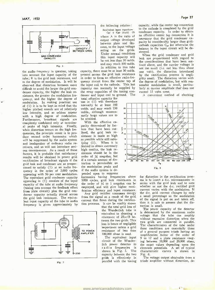
MAY, 1932
I
I -Cqf
I 1-i T ,, __,._, ___,,,,...,r J , ' -iC9f CAPACITY )
/ , BETWEEN GRIDS
l GRID CONDENSER
CAPACITY
Fig. 5
the audio frequency in question, taking into account the input capacity of the tube; R is the grid leak resistance, and m the degree of modulation. It will be observed that distortion becomes more difficult to avoid the larger the grid con- denser capacity, the higher the leak re- sistance, the greater the modulation fre- quency, and the higher the degree of modulation. In making practical use of (1) it is to be kept in mind that the higher pitched sounds are of relatively low intensity, and so seldom appear with a high degree of modulation. Furthermore, broadcast signals are completely modulated only at occasion- al peaks of high intensity. Finally, when distortion occurs on the high fre- quencies, the principle result is to pro- duce second order harmonics which will be suppressed by the audio system and loudspeaker of ordinary radio re- ceivers, and so will not introduce seri- ous consequences. As a result of these factors, it is probable that satisfactory results will be obtained in power grid rectification of broadcast signals if the grid leak and condenser are so propor- tioned to satisfy (1) at an audio fre- quency in the order of 3,000 cycles appearing with 50 per cent modulation. The equivalent grid condenser capacity appearing in (1) consists of the input capacity of the tube at audio frequency (taking into account the feedback effect from plate circuit) plus the grid con- denser capacity actually placed across the grid leak resistance. The equiva- lent input capacity of the tube to audio frequency is given approximately by
Fig. 7
the following relation: Equivalent input capacity=
Cgi + Cgp (1+A) (2)
where A is the ratio of output voltage developed between plate and fila- ment, to the input voltage acting on the grids. Under normal conditions this input capacity will be not less than 50 uufds. and may reach 100 uufds. In addition to this tube
capacity, there must be at least 50 uufds. present across the grid leak resistance in order to form an effective radio -fre- quency circuit from the center tap of the input coil to the cathode. This last capacity can normally be supplied by the stray capacities of the tuning con- denser and input coil to ground. The total effective capacity for use in (1) will therefore normally be at least 100 uufds. and may reach 150 uufds., although unneces- sarily large values are to be avoided.
With the effective ca- pacity determined by fac- tors that have been out- lined, the grid leak re- sistance is made as high as possible while still satis- fying (1). When it is desired to obtain extremely high quality, the leak re- sistance should be in the order of / megohm, but if a certain amount of dis- tortion is permissible on the modulation peaks and if the audio system is de- pended upon to suppress harmonics having frequencies above 5000 cycles, grid leak resistances in the order of / to 1 megohm can be employed, and will give higher recti- fication efficiency and input resistance.
Any grid rectifier consumes energy from the signal as a result of the grid current that flows during the rectifica- tion processs. It can be readily shown
that the total grid loss of the Wunderlich tube is equivalent to shunting a resistance of 2Ree /B be- tween the two grids. This loss is hence of negligible importance unless a grid
TO POWER resistance of less than AMPLIFIER 100,000 ohms is used.
The equivalent input circuit of the Wunder - lich power detector to r a d i o frequencies is shown in Fig. 5. The capacity between the two grids is effectively in parallel with the tuning
20
18
le
14
12
= 10
6
4
2
o
Page 27
capacity, while the center tap connection to the cathode is completed by the grid condenser capacity. In order to obtain an effective center tap connection it is necessary that the grid condenser ca- pacity be considerably larger than grid - cathode capacities Co for otherwise the balance in the input circuit will be de- stroyed:
When the grid condenser and grid leak are proportioned with regard to the considerations that have been out- lined above, and the carrier voltage is not too small ( i.e. not less than about one volt), the distortion introduced by the rectification process is negli- gibly small. The distortion varies with the degree of modulation, but with rea- sonable modulation is small, particu- larly at carrier amplitude that- does not exceed 15 volts crest.
A convenient method of checking
I -_ e
_ -. 4.
% qy
it A
',4P, %''. k
,0
.. _ -.E,.'v, i I \I ,.
:,..,M z
.//1rIII r1 '"
. / /%, i0 --DANC G'-wR.... S° ' ° i
140 160 1e0 200 220 ̀
240 20 40 60 eo oo 120
Ee
Fig. 6
for distortion in the rectification proc- ess is to insert a d -c. microammeter in series with the grid leak and to note whether or not the d -c. rectified grid current varies with the modulation. If the d-c. grid current changes by only a small percentage as the modulation of the signal is put on and taken off, then it is safe to assume that the dis- tortion is small.
The power capacity of the detector is determined by the maximum audio voltage that the tube can amplify without excessive distortion when the two grids are connected in parallel. The characteristics of the tube under these conditions are essentially those of a general purpose triode having an amplification factor of the order of 9 to 12 and a plate resistance rang- ing between 10,000 and 20,000 ohms, the exact values depending upon the electrode potentials. A set of typical characteristic curves is shown in Fig. 6.
The voltage output obtainable from a triode amplifier without distortion, de-
www.americanradiohistory.com
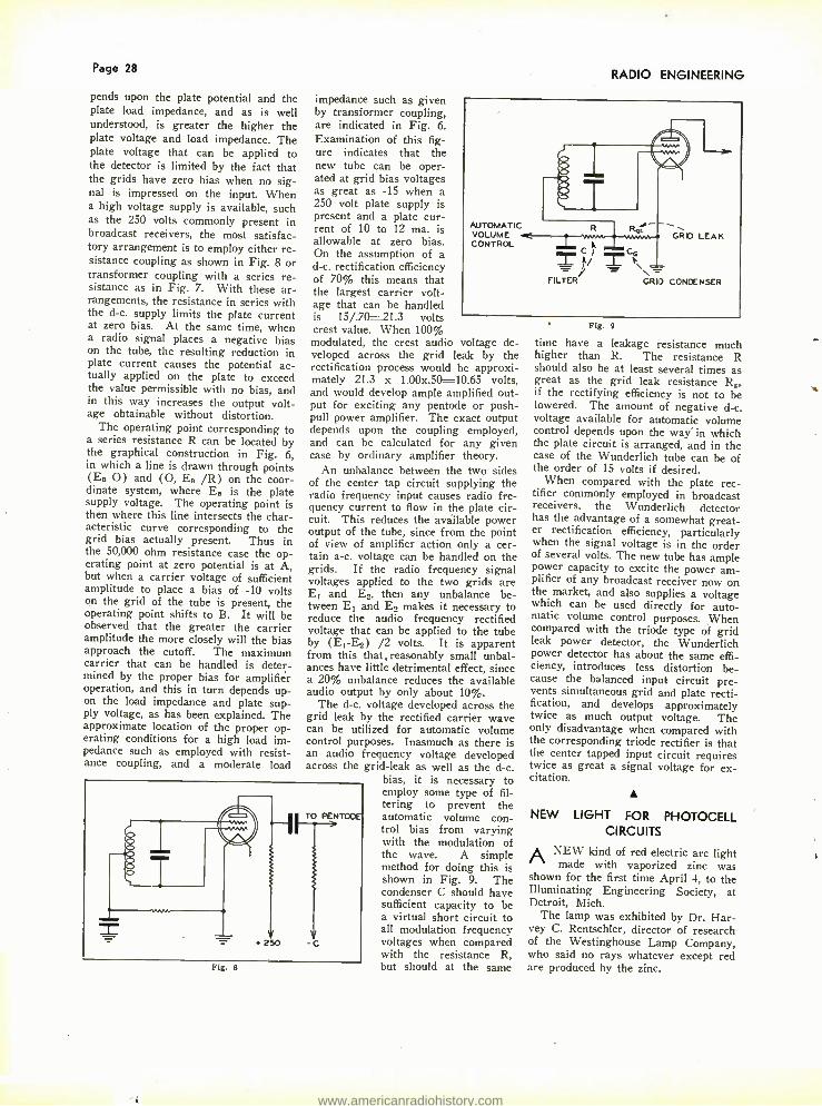
Page 28
pends upon the plate potential and the plate load impedance, and as is well understood, is greater the higher the plate voltage and load impedance. The plate voltage that can be applied to the detector is limited by the fact that the grids have zero bias when no sig- nal is impressed on the input. When a high voltage supply is available, such as the 250 volts commonly present in broadcast receivers, the most satisfac- tory arrangement is to employ either re- sistance coupling as shown in Fig. 8 or transformer coupling with a series re- sistance as in Fig. 7. With these ar- rangements, the resistance in series with the d -c. supply limits the plate current at zero bias. At the same time, when a radio signal places a negative bias on the tube, the resulting reduction in plate current causes the potential ac- tually applied on the plate to exceed the value permissible with no bias, and in this way increases the output volt- age obtainable without distortion.
The operating point corresponding to a series resistance R can be located by the graphical construction in Fig. 6, in which a line is drawn through points (EH O) and (O, E. /R) on the coor- dinate system, where E. is the plate supply voltage. The operating point is then where this line intersects the char- acteristic curve corresponding to the grid bias actually present. Thus in the 50,000 ohm resistance case the op- erating point at zero potential is at A, but when a carrier voltage of sufficient amplitude to place a bias of -10 volts on the grid of the tube is present, the operating point shifts to B. It will be observed that the greater the carrier amplitude the more closely will the bias approach the cutoff. The maximum carrier that can be handled is deter- mined by the proper bias for amplifier operation, and this in turn depends up- on the load impedance and plate sup- ply voltage, as has been explained. The approximate location of the proper op- erating conditions for a high load im- pedance such as employed with resist- ance coupling, and a moderate load
impedance such as given by transformer coupling, are indicated in Fig. 6. Examination of this fig- ure indicates that the new tube can be oper- ated at grid bias voltages as great as -15 when a 250 volt plate supply is present and a plate cur- rent of 10 to 12 ma. is allowable at zero bias. On the assumption of a d -c. rectification efficiency of 70% this means that the largest carrier volt- age that can be handled is 15/.70 =21.3 volts crest value. When 100% modulated, the crest audio voltage de- veloped across the grid leak by the rectification process would be approxi- mately 21.3 x 1.00x.50 =10.65 volts, and would develop ample amplified out- put for exciting any pentode or push - pull power amplifier. The exact output depends upon the coupling employed, and can he calculated for any given case by ordinary amplifier theory.
An unbalance between the two sides of the center tap circuit supplying the radio frequency input causes radio fre- quency current to flow in the plate cir- cuit. This reduces the available power output of the tube, since from the point of view of amplifier action only a cer- tain a -c. voltage can be handled on the grids. If the radio frequency signal voltages applied to the two grids are E1 and E:, then any unbalance be- tween E1 and E., makes it necessary to reduce the audio frequency rectified voltage that can be applied to the tube by (E1 -E2) /2 volts. It is apparent from this that.reasonably small unbal- ances have little detrimental effect, since a 20% unbalance reduces the available audio output by only about 10 %.
The d -c. voltage developed across the grid leak by the rectified carrier wave can be utilized for automatic volume control purposes. Inasmuch as there is an audio frequency voltage developed across the grid -leak as well as the d -c.
bias, it is necessary to employ some type of fil- tering to prevent the automatic volume con- trol bias from varying with the modulation of the wave. A simple method for doing this is shown in Fig. 9. The condenser C should have sufficient capacity to be a virtual short circuit to all modulation frequency voltages when compared with the resistance R, but should at the same
RADIO ENGINEERING
+ 250
TO PENTODE
Fig. 8
Fig. 9
time have a leakage resistance much higher than R. The resistance R should also be at least several times as great as the grid leak resistance R,. if the rectifying efficiency is not to be lowered. The amount of negative d -c. voltage available for automatic volume control depends upon the way' in which the plate circuit is arranged, and in the case of the Wunderlich tube can be of the order of 15 volts if desired.
When compared with the plate rec- tifier commonly employed in broadcast receivers, the Wunderlich detector has the advantage of a somewhat great- er rectification efficiency, particularly when the signal voltage is in the order of several volts. The new tube has ample power capacity to excite the power am- plifier of any broadcast receiver now on the market, and also supplies a voltage which can be used directly for auto- matic volume control purposes. When compared with the triode type of grid leak power detector, the Wunderlich power detector has about the same effi- ciency, introduces less distortion be- cause the balanced input circuit pre- vents simultaneous grid and plate recti- fication, and develops approximately twice as much output voltage. The only disadvantage when compared with the corresponding triode rectifier is that the center tapped input circuit requires twice as great a signal voltage for ex- citation.
NEW LIGHT FOR PHOTOCELL CIRCUITS
A NEW kind of red electric arc light made with vaporized zinc was
shown for the first time April 4, to the Illuminating Engineering Society, at Detroit, Mich.
The lamp was exhibited by Dr. Har- vey C. Rentschler, director of research of the Westinghouse Lamp Company, who said no rays whatever except red are produced by the zinc.
www.americanradiohistory.com

MAY, 1932 Page 29
Loudspeakers with independent control added to radio receivers
By W. L. PARSONS*
THE addition of extra speakers to radio sets opens further profitable business to the serviceman and dealer. Any good radio set having
adequate output stages of amplification will successfully operate one or more additional speakers. Very satisfactory results can be obtained by the selection of good speakers and the proper volume control with a close observance to im- pedance matching that is possible with- out the aid of special equipment.
Home owners will always be inter- ested in separate speakers in the recrea- tion room, the den, possibly the bed- room or kitchen.
Restaurants, ice cream parlors, lodge rooms. schools and other public places
'are all potential customers for one or more additional speakers, or for com- plete sound installations. To make such installations practical, and faithful in reproduction, locate a volume control with each speaker that will adjust its volume from maximum to minimum without affecting the volume of the speaker in the set or other speakers on the same amplifier.
It is well to consider the various types of output push pull, parallel and single -45, -50 and pentode tubes. The output impedance of these various sys- tems is as follows: -45, -50 tubes in push pull 8,000 ohms. Parallel 2,000 ohms. Single 4,000 ohms. Pentodes in push pull 14,000 ohms parallel 3,500 ohms, single 7,000 ohms.
The method of connecting additional speakers is illustrated in Fig. 1 which shows connection for push -pull tubes. Fig. 2 shows connections for parallel or single tubes and Fig. 3 for multiple connection of speakers. Multiple con- nection of speakers is recommended for
*Engineer, Central Radio Laboratories.
NJI(A N
sfr
SINGLE OR Be PARALLEL OUTPUT
Fig. 1. Push -pull circuit for two loudspeakers.
output systems of push -pull or parallel power tubes. More than one additional speaker is not recommended on single power tube sets.
Magnetic speakers similar to the Western Electric 540 AW and 560 AW having an impedance of 10,000 ohms at 1,000 cycles are excellent for use as additional speakers. The L pad No. 74- 544, 10,000 ohms is recommended for multiple installations. or the L pad 96- 003 for single or group control unit,
Fig. 2. Parallel or single tube circuit for two loudspeakers.
from amplifiers using 250 tubes in par- allel or push -pull.
The arrangement of multiple speak- ers should have a total impedance equal to or greater, but never less than the output impedance of the amplifier. For example, if two magnetics are paral- leled, the total impedance will be half of the impedance of one or 5,000 ohms ;
if the speakers are connected in series the impedance is doubled or 20,000 ohms. See Fig. 3 for connection whose total impedance is 10,000 ohms. If two speakers are desired on an output sys- tem it is better to connect them in series rather than in parallel as the parallel impedance would only be 5,000 ohms and cause a loss in power and a cutoff of the high frequencies. The use of not more than 12 magnetics on push - pull or parallel -50, 8 magnetics for push -pull -45 or pentodes, and one magnetic on single -45 or pentode is recommended. The above recommenda- tions do not apply to public address am- plifiers where special output transform- ers provide accurate matching of im- pedance values.
Dynamic speakers are usually rated by the manufacturer as having trans- formers to match tubes in push -pull or
IA
iv PUSH PULL OUTPUT
Fig. 3. Multiple connection of loudspeakers.
single -45, -50, or pentodes, It is only necessary to consider a dynamic, with a transformer for push -pull or single -45 or -50 tubes, as proper connec- tions either in series or parallel can be made to match the output systems. If only one speaker is to be added to a push -pull pentode system then it is necessary to obtain a speaker with a transformer for push -pull pentodes.
However, if more than one is to be added a series connection of two dyna- mics with transformers for push -pull -45 or -50 tubes will have an im- pedance of 16,000 ohms and will oper- ate satisfactorily.
An L pad for dynamic speakers, trans- former for push -pull -45 or -50 in multiple or single is No. 96 -003, 10,000 ohms. The No. 96 -004, 15,000 ohms, is for use on a dynamic with pentode push -pull transformer.
It must be remembered that we are not considering the use of a regular radio set as a centralized public -address system. Successful operation can only be obtained by religiously adhering to recommended methods. As long as the impedance of the load exceeds or equals the output impedance, and good con- trols and speakers are used, satisfactory performance will be assured. Many live opportunities lie waiting in this field and properly exploited, will prove profit- able.
Although it is not indicated in the diagrams, the insertion of condensers in series with the high potential leads to the speaker lines is advisable. These condensers should be 2mfd. capacity 300 volts d -c. of the paper and foil type. The use of condensers in these positions prevents the high d -c. plate potential from being applied to the speaker line, and in the case of a short circuit in the external connections from injuring the radio power supply. In the push -pull circuit a condenser in the lead from each plate is necessary.
ALLOYS FOR MAGNETIC CORES The alloy, particularly the iron- nickel-
cobalt type, is quenched in water, when molten, and subsequently pulverized. If desired, additions of embrittling ma- terials, ex. iron oxide or iron sulfide, may be added. -International Standard Electric Corp. Apps. (United States) January 31. 1929. Appl. (Germany) September 8, 1929. Issued October 27, 1931.
www.americanradiohistory.com

Page 30 RADIO ENGINEERING
Frequency control monitor for broadcast stations
I the Federal Radio Commission's General Or- der der No. 116, compelling broadcasters to remain with-
in 50 cycles of their assigned wave- lengths, to go into effect June 22, a de- vice has been perfected by which sta- tions can maintain a constant check on their frequencies and consequently cor- rect their transmitters the instant it becomes necessary. The device is a "frequency monitoring" unit, designed for the Western Electric Company by Bell Telephone Laboratories.
The monitoring unit is small and compact, measuring only 12/ by 13% by 17 inches. Up to the present, more elaborate equipment has been needed to test the frequencies of transmitters. Most stations have been having periodic tests made by laboratories where such equipment is available. Now the Radio Commission order will not only com- pel strict adherence to assigned fre- quencies, but also require that stations themselves have a method of checking their frequencies.
The monitoring unit can be connected into any stage of the transmitter or used entirely apart from it by means of an antenna. This flexibility is made possible by the fact that the input may
THE operator of Station WUCG, the radio station in United Air Lines' hangar at the Chicago mu- nicipal airport, is a busy man.
A tri- motored Boeing air liner with passengers and mail had just taken off for San Francisco and the operator sent the dispatch.
While he listened, the message was repeated in sequence by operators at Iowa City, Des Moines, Omaha, Lin- coln and North Platte, airports along the plane's route. The operator at Chey- enne, the last station in that division of the California -bound plane, heard the message and sent an "O. K., it's clear," skipping back from station to station, to the Chicago headphones.
The relayed message and its answer on this 1,000 -mile span takes only one
come from either a modulated or un- modulated source without affecting the accuracy of the device.
The impulses from the transmitter are introduced into the monitoring unit, passed through a stage of amplification and into a detector tube. The unit con- tains a quartz crystal oscillator which oscillates at the assigned carrier fre- quency. The output from this oscilla- tor is also passed through a stage of amplification and fed into the same de- tector. The output of the detector con- tains the beat note or difference fre- quency. This difference frequency is registered on a visual indicator kept un-
:=oSoa'ä CYCLES
.o. 700 OSCILLATOR MO. ET1*
v1CWY TUBE
der observation by the station's tech- nician.
A self- restoring button mounted on the front of the panel permits a small temporary displacement of the fre- quency of the monitoring oscillator. From this the operator sees on the same indicator whether the deviation shown is high or low with respect to that of the monitoring equipment.
Complete power supply for the vac- uum tubes and crystal heater is includ- ed in the unit. The unit is entirely a -c. operated and the power source may be either the 110 or 220 volt, 50 to 60 cycle a -c. supply. The only power connection necessary to set the unit in operation is by cord and plug to the commercial power source.
In addition to being used directly on the transmitter under test, the monitor- ing unit may be connected to ordinary radio receiving sets, except those of the superheterodyne type. This makes it possible for a station executive, for ex- ample, to keep his transmitter under ob- servation by attaching the unit to a radio receiver in his home or office.
O.Of3. 90.271A Y.{UUY TUBE v.cuw. TUSE
,a.ael v.CYW TUBE
ill Irt MA-r MEI Mill
i
WANED! MO.EI tiCuu ;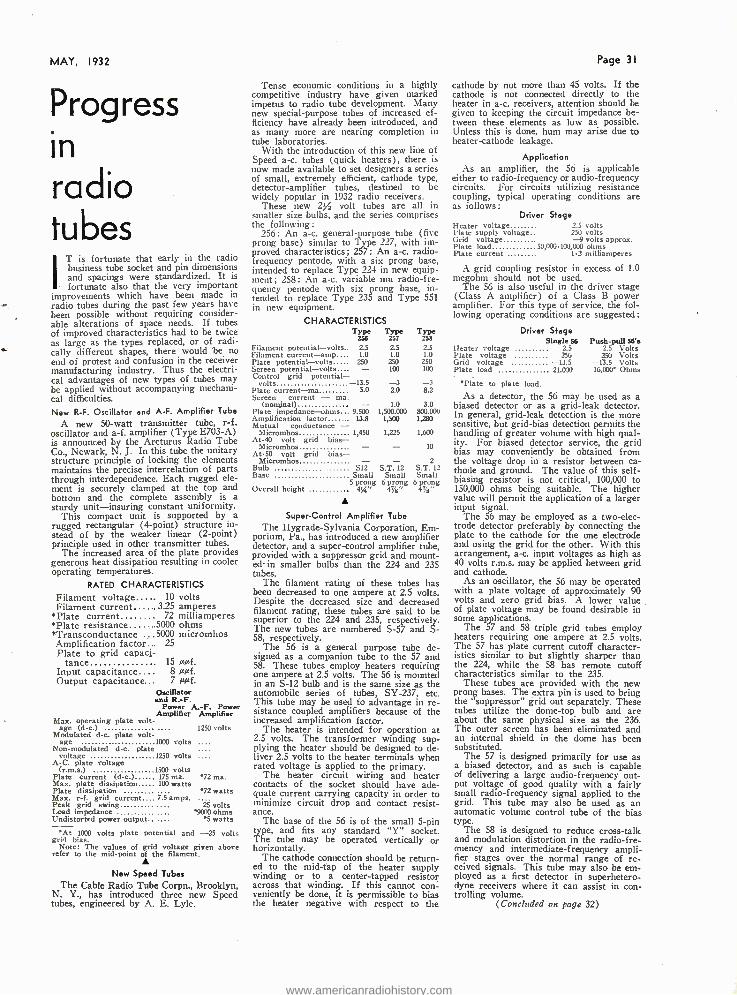
MAY, 1932 Page 3I
Progress in radio tubes
IT is fortunate that early in the radio business tube socket and pin dimensions and spacings were standardized. It is fortunate also that the very important
improvements which have been made in radio tubes during the past few years have been possible without requiring consider- able alterations of space needs. If tubes of improved characteristics had to be twice as large as the types replaced, or of radi- v tally different shapes, there would be no end of protest and confusion in the receiver manufacturing industry. Thus the electri- cal advantages of new types of tubes may be applied without accompanying mechani- cal difficulties. New R -F. Oscillator and A -F. Amplifier Tube
A new 50 -watt transmitter tube, r -f. oscillator and a -f. amplifier (Type E703-A) is announced by the Arcturus Radio Tube Co., Newark, N. J. In this tube the unitary structure principle of locking the elements maintains the precise interrelation of parts through interdependence. Each rugged ele- ment is securely clamped at the top and bottom and the complete assembly is a sturdy unit- insuring constant uniformity.
This compact unit is supported by a rugged rectangular (4- point) structure in- stead of by the weaker linear (2- point) principle used in other transmitter tubes.
The increased area of the plate provides generous heat dissipation resulting in cooler operating temperatures.
RATED CHARACTERISTICS Filament voltage 10 volts Filament current 3.25 amperes
«Plate current 72 milliamperes «Plate resistance ..5000 ohms *Transconductance ...5000 micromhos Amplification factor... 25 Plate to grid capaci-
tance . 15 aµf. Input capacitance.... 8 oaf. Output capacitance... 7aµ f.
Oscillator and R. -F.
Power A. -F. Power Amplifier Amplifier
Max. operating plate volt- age (d -c.) ... 1250 volts
Modulated d -c. plate volt- age 1000 volts ....
Non -modulated d -c. plate .... voltage 1250 volts ....
A -C. plate voltage (r.m.s.)
Plate current (d -c.) Max. plate dissipation
1500 volts 175 ma. 72 ma. 100 watts
Plate dissipation /2 watts Max. r -f. grid current.... 7.5 amps. Peak grid swing 25 volts Load impedance .... '9000 ohms Undistorted power output...... `5 watts
At 1000 volts plate potential and -25 volts grid bias.
Note: The values of grid voltage given above refer to the mid -point of the filament.
New Speed Tubes The Cable Radio Tube Corpn., Brooklyn,
N. Y., has introduced three new Speed tubes, engineered by A. E. Lyle.
Tense economic conditions in a highly competitive industry have given marked impetus to radio tube development. Many new special -purpose tubes of increased ef- ficiency have already been introduced, and as many more are nearing completion in tube laboratories.
With the introduction of this new line of Speed a -c. tubes (quick heaters), there is now made available to set designers a series of small, extremely efficient, cathode type, detector -amplifier tubes, destined to be widely popular in 1932 radio receivers.
These new 2%2 volt tubes are all in smaller size bulbs, and the series comprises the following:
256: An a -c. general -purpose tube (five prong base) similar to Type 227, with im- proved characteristics; 257: An a -c. radio - frequency pentode, with a six prong base, intended to replace Type 224 in new equip- ment; 258 : An a -c. variable mu radio-f re- quency pentode with six prong base, in- tended to replace Type 235 and Type 551 in new equipment.
CHARACTERISTICS Type
256 Type Type
257 258
Filament potential- volts 2.5 2.5 2.5 Filament current -amp 1.0 1.0 1.0 Plate potential -volts 250 250 250 Screen potential -volts 100 100 Control grid potential -
volts -13.5 -3 -3 Plate current -ma 5.0 2.0 8.2 Screen current - ma.
(nominal) 1.0 3.0 Plate impedance-ohms 9,500 1,500,000 800,000 Amplification factor . 13.8 1,500 1.280 Mutual conductance -
Micromhos 1,450 1,225 1,600 At -40 volt grid bias -
Micromhos - 10 At -50 volt grid bias -
Micromhos - - 2 Bulb S12 S.T. 12 S.T. 12 Base Small Small Small
5 prong 6 prong 6 prong Overall height 434" 4jíz' 4r /s"
Super -Control Amplifier Tube The Hygrade -Sylvania Corporation, Em-
porium, Pa., has introduced a new amplifier detector, and a super -control amplifier tube, provided with a suppressor grid and mount - ed- in smaller bulbs than the 224 and 235 tubes.
The filament rating of these tubes has been decreased to one ampere at 2.5 volts. Despite the decreased size and decreased filament rating, these tubes are said to be superior to the 224 and 235, respectively. The new tubes are numbered S -57 and S- 58, respectively.
The 56 is a general purpose tube de- signed as a companion tube to the 57 and 58. These tubes employ heaters requiring one ampere at 2.5 volts. The 56 is mounted in an S -12 bulb and is the same size as the automobile series of tubes, SY -237, etc. This tube may be used to advantage in re- sistance coupled amplifiers because of the increased amplification factor.
The heater is intended for operation at 2.5 volts. The transformer winding sup- plying the heater should be designed to de- liver 2.5 volts to the heater terminals when rated voltage is applied to the primary.
The heater circuit wiring and heater contacts of the socket should have ade- quate current carrying capacity in order to minimize circuit drop and contact resist- ance.
The base of the 56 is of the small 5 -pin type, and fits any standard "Y" socket. The tube may be operated vertically or horizontally.
The cathode connection should be return- ed to the mid -tap of the heater supply winding or to a center -tapped resistor across that winding. If this cannot con- veniently be done, it is permissible to bias the heater negative with respect to the
cathode by not more than 45 volts. If the cathode is not connected directly to the heater in a -c. receivers, attention should be given to keeping the circuit impedance be- tween these elements as low as possible. Unless this is done, hum may arise due to heater -cathode leakage.
Application As an amplifier, the 56 is applicable
either to radio -frequency or audio- frequency circuits. For circuits utilizing resistance coupling, typical operating conditions are as follows:
Driver Stage Heater voltage 2.5 volts Hate supply voltage 250 volts Grid voltage -9 volts approx. Plate load 50,000 - 100,000 ohms Plate current 1.2 milliamperes
A grid coupling resistor in excess of 1.0 megohm should not be used.
The 56 is also useful in the driver stage (Class A amplifier) of a Class B power amplifier. For this type of service, the fol- lowing operating conditions are suggested:
Driver Stage Single 56 Push -pull 56's
Heater voltage 2.5 2.5 Volts Plate voltage 25G 250 Volts Grid voltage -13.5 -13.5 Volts Plate load 21,000 16,000. Ohms
*Plate to plate load.
As a detector, the 56 may be used as a biased detector or as a grid -leak detector. In general, grid -leak detection is the more sensitive, but grid -bias detection permits the handling of greater volume with high qual- ity. For biased detector service, the grid bias may conveniently be obtained from the voltage drop in a resistor between ca- thode and ground. The value of this self - biasing resistor is not critical, 100,000 to 150,000 ohms being suitable. The higher value will permit the application of a larger input signal.
The 56 may be employed as a two -elec- trode detector preferably by connecting the plate to the cathode for the one electrode and using the grid for the other. With this arrangement, a-c. input voltages as high as 40 volts r.m.s. may be applied between grid and cathode.
As an oscillator, the 56 may be operated with a plate voltage of approximately 90 volts and zero grid bias. A lower value of plate voltage may be found desirable in some applications.
The 57 and 58 triple grid tubes employ heaters requiring one ampere at 2.5 volts. The 57 has plate current cutoff character- istics similar to but slightly sharper than the 224, while the 58 has remote cutoff characteristics similar to the 235.
These tubes are provided with the new prong bases. The extra pin is used to bring the "suppressor" grid out separately. These tubes utilize the dome -top bulb and are about the same physical size as the 236. The outer screen has been eliminated and an internal shield in the dome has been substituted.
The 57 is designed primarily for use as a biased detector, and as such is capable of delivering a large audio -frequency out- put voltage of good quality with a fairly small radio -frequency signal applied to the grid. This tube may also be used as an automatic volume control tube of the bias type.
The 58 is designed to reduce cross -talk and modulation distortion in the radio -fre- ouency and intermediate -frequency ampli- fier stages over the normal range of re- ceived signals. This tube may also be em- ployed as a first detector in superhetero- dyne receivers where it can assist in con- trolling volume.
(Concluded on page 32)
www.americanradiohistory.com

Page 32 RADIO ENGINEERING
These tubes are flexible as to circuit considerations because the suppressor grid may be used to control various characteris- tics such as selectivity and volume control action.
The suppressor grid employed in the de- sign of these tubes is placed between the screen and the plate and has its own base pin connection. The suppressor may or may not be connected to the cathode ter- minal, depending upon receiver design re- quirements.
When these two terminals are connected directly together, the suppressor is ef- fective in eliminating the secondary emis- sion effects which limit the voltage swing permissible in the usual screen -grid tube at low plate voltage, that is, at a plate voltage approximately equal to the screen voltage. The suppressor, therefore, makes possible the efficient operation of this type at a relatively low plate voltage. This may be greater than, equal, to, or slightly less than the recommended screen voltage.
RCA Radiofron-E. T. Cunningham
The R C A Radiotron Company, Inc., and E. T. Cunningham, Inc. have an- nounced five new types of RCA radiotrons and Cunningham radio tubes, designed as
RCA -46 and C -46... RCA -56 and C -56... RCA -57 and C -57... RCA -58 and C.58...
RCA -82 and CX -82.
.Class B power amplifier
.General purpose triode
.Triple -grid amplifier detector
.Triple -grid supercontrol amp. lifier
.Full -wave mercury vapor rectifier
The 46 is designed particularly for ser- vice in Class B audio amplifier circuits of a -c. operated receivers. A pair of these tubes in a Class B output stage is capable of supplying economically a reserve of power to meet requirements for an ex- tended volume range. The 46 is construct- ed so that its two grids may be connected in the circuit to make the tube applicable either to the output or the driver stage of a Class B amplifier.
The 56 is a general purpose triode of the a-c. heater type and is recommended for service as detector, amplifier or oscillator.
The 57 is a triple -grid amplifier detector which makes use of a suppressor and a radically new construction to obtain super- ior performance capabilities.
The 58 is a triple -grid super -control amplifier similar in construction to the 57, but designed to operate effectively over a large range of signal voltages, either with manual or automatic volume control cir- cuits.
The 82 is designed especially for supply- ing a -c. receivers with d -c. power of uni- form voltage independent of variations in the direct current demand. This feature makes this tube uniquely suitable for use in receivers employing Class B power am- plifiers.
The design of the 56, 57, and 58 is char- acterized by relatively low heater power consumption, small size, and excellent char- acteristics. Both the 57 and the 58 have the unique feature of having the suppressor lead brought out to its own terminal.
Radio engineers will appreciate the flex- ible adaptability of these five new types in providing unique opportunities for the development of improved receiver circuits. These new types are recommended for use only in receivers designed for their char- acteristics.
The dome top bulb makes possible close proximity of the external and internal shields. The close spacing of the two shields makes available a low effective grid -plate capacitance. The form of the external shield -can may be somewhat modi- fied depending upon the receiver design re-
1IIIIIIIIIIIIIIIIIIIIIIIIIIIIIIIIIIII1111111IIIII I1111
RCA Radiotron, Triple Grid, 57
IIIIIIIIIIIIIII IIIIIIIIIÜl1111II111111111111111111 IIII
quirements for minimum grid- plates and output capacitance.
Rating and characteristics of the 57 are as follows:
GENERAL
Heater voltage.... 2.5 volts a -c. or d -c. Heater current.... 1.0 ampere Direct interelectrode capacitances:
Effective grid - plate .0.010 if max. (With
µµf shield can)
5.2 6.8 µµf
Input Output
Overall length... .4 -19/32 to 4 -27/32 ins. Max. diameter.... 1 -9/16 ins. Bulb St -12 (dome shape) Cap .Small metal Base Small 6 -pin
AMPLIFIER (CLASS A)
Operating conditions and characteris- tics :
Heater voltage 2.5 volts Plate voltage 250 volts maximum .
Screen voltage 100 volts maximum Grid voltage . -3 volts Atnplificat'n factorGreater than 1.500 Plate resistance Greater than 1.5 me-
gohms Mutual conduct-
ance 1 225 nticromhos Grid voltage f
cathode current cutoff 7 volts, approx.
Plate current 2.0 milliamperes Screen current 1.0 milliampere max.
DETECTOR
Operating conditions as biased detector :
Heater voltage 2.5 volts Plate voltage 250 volts maximum Screen voltage 100 volts maximum Grid voltage -6 volts approx. Plate load- 250.000 ohms or 500 henry
choke shunted by ' a .25 niegohm resistor. For resistance load, plate supply voltage will be voltage at plate plus voltage drop in load caused by specified plate current.
Plate current -Adjusted to approximate- ly 0.1 milliampere with no a -c. input signal.
The base of the 57 is of the small 6 -pin type. Its pins require the use of a standard six- contact socket which may be installed to operate the tube either in a vertical or in a horizontal position. For horizontal operation. the socket should be positioned with its heater pin openings one vertically above the other.
New Photocell
The Luxtron Mfg. Co., Inc., 241 Lafay- ette Shreet, New York, announces a new, inexpensive photocell which operates a re- lay without amplification. The Lux -Tron cell ST, and relay type g. -1, marketed by this company are said to be efficient and useful.
Cathode Rey Tubes
The Globe Television and Phone Corpn., Starrett -Lehigh building, New York, is marketing a new line of cathode ray tubes. These range in size from a small unit similar to a -45 power tube to units nine inches in diameter. The prices range from $7.50 to $80.00. The characteristics of a five -inch type are:
Filament voltage, 0.5 -1 volt. Filament current, 5 amperes. Accelerating electrode voltage, 400 -1,000
volts. Sensitivity, 1.0 mm. per volt, each set
of plates. The sensitivity refers to the distance the
electronic stream will be deflected by the indicated voltage change impressed on the plates.
New Tube for New Receiver
The Mcllvane Patent Corporation, St. Charles, Ill., has been granted U. S. pat- ent No. 1,853,914 covering heater type a -c. tubes. The company also has been granted patent No. 1,851,440 covering a new idea in radio receivers. The tubes used are of the electronic expulsion type in which the cathode may be several inches square of caesium or tungsten film.
This thermionic tube comprises a plate, a grid and a cathode, the latter including terminals and a filamentary structure con- nected between the terminals and compris- ing adjacent non -contiguous portions which exhibit opposite electric polarity when the terminals are connected to 110 v., a -c. mains.
50 -Watt Amplifier Tube
A new 50 -watt tube for sound, public address and laboratory work is being marketed by the Wakefield Television and Radio Carpi., 27 Hoyt St., Newark, N. J. Its characteristics are: Filament voltage 10 Volts Filament current 3 25 Amperes *Plate current 72 Milliamperes `Plate Resistance 2100 Ohms 'Tran'sconductarice 2380 Micromhos Amplification factor 5 Plate to grid capacitance 15 mmf. Input capacitance 8 mmf.
Output capacitance 7 mmf.
A. F. Power Amplifier Class A Modulator
Maximum operating plate voltage (d- c.)... 1250 Volts 1250 Volts
Maximum plate dissipa- tion 75 Watts 75 Watts
`Plate dissipation 75 Watts *Plate current (d- c.) 75 nia. 75 ma. `Peak grid swing 145 Volts 145 Volts *Load impedance 8000 Ohms 'Undistorted power out-
put 20 Watts `Modulation factor .. .06 `Oscillator input per
modulator tube 120
At 1000 volts plate potential and -150 volts grid bias.
NOTE: Thé values of grid voltage given above refer t', the mid -point of the filament.
This tube is eauiva lent to, and interchange- able with Navy Type 3945 and Type 545.
www.americanradiohistory.com

MAY, 1932 Page 33
OHIOHM RESISTOR OHM DIAL
OHIOHM RESISTORS
R. M. A COLOR CODE
OHIO CARBON IOU MIA ROAD
Have you received one of these handy, instant color code dials for determining resistance? Yours for the asking.
As one manufacturer to Another
Suppose we swap places for the time being. You manufacture re- sistors; we'll make receivers. What quality of resistors would you recommend? Anything short of the best? What kind of sets would we turn out -what amount
[[ OHIOHM MOOELXD
CLEVELANO, Q U
of grief could we expect -if we bought parts indiscriminately?
The smallest, most obscure little part in any man's set might be the making or the breaking of public acceptance and dealer good -will.
OHIOHM SPARK SUPPRESSORS
Eliminate ignition int erference on automobile radios - a growing market. These suppressors have a non- moisture absorbing glaze. preventing
shorting. Model XD for Ilse in renter connection of distributor cup. Model XI' for either horizontal or vertical mounting on plug.
OHIOHMS Among the FIRST made resistors - the LATEST in development
THE OHIO OHIO CARBON CO. CLEVELAND, OHIO, U. S. A.
www.americanradiohistory.com

Page 34
E ` S` .. o r . sae! . f.. Na .r
9lfe1 00( A p qöi P:ñ'
__- ú S
s r .n . h t 0.. . I = e. 9 .C r ® c
_ ¡"n" a i óiióa I -- .:
__R., -1 . . r _ _ , .a ma
RADIO ENGINEERING
SHORTWAVE AND TELEVISION CORP'N A. M. Morgan, general manager of the
Shortwave and Television Corporation, ad- vises that the New York offices of the company have been closed and that Walter S. Lemmon, formerly vice -president is no longer connected with the company. The company's offices are at 70 Brookline ave., Boston, Mass.
TUNG -SOL LAMP REPORTS
Tung -Sol Lamp Works, Inc., and sub- sidiary companies, manufacturers of auto- mobile and flashlight bulbs and radio tubes, report net profit in 1931 of $352,864.92 which is equal to 75 cents per share on the common stock, after deducting dividend of $3 per share on the preferred. The com- pany's balance sheet as of December 31, 1931 shows an excellent liquid condition, with cash on hand of $284,149.59 which is in excess of double total current liabilities. Total current assets, including marketable securities and merchandise inventories, amount to $1,498,844.31 and are more than ten times total current liabilities of $131; 517.58. Reduced selling costs and operat- ing expenses, together with improved pro- duction methods, are cited by Harvey W. Harper, president, as responsible for the company's favorable showing in the face of generally adverse conditions in the major industries which absorb its output.
-
KOLSTER FORGES AHEAD A substantial increase in the working
forces in the last month has been added at the factories of Kolster Radio, Inc., at 360 Thomas Street, Newark, N. J.
"In the last month we have added more than 300 employees," announces S. T. Thompson, vice -president of Brandes Prod- ucts Corporation, the manufacturing sub- sidiary of Kolster Radio. "We have found this to be necessary in order that our pro- duction might keep pace with our sales. The number of workers we now have is sufficient to take care of our production for the next two months. In June we ex- pect that as increased orders are received from dealers in all parts of the country, this force will be materially augmented.
"In the last three weeks we have shipped several thousand sets out of the factory. These sets are all made up on order. They are sold. According to our present plans, we shall keep on the same production schedule fo* the next eight weeks. Pres- ent indications are that in June we shall be obliged to step up our output consider- ably." A
ANNUAL REPORT OF THE ARCTURUS RADIO TUBE COMPANY
"Omitting provision for depreciation and amortization of book values," stated Presi- dent Chester H. Braselton, of The Arc- turus Radio Tube Co., Newark, N. J., "the 1931 operations were conducted at a profit. The company practically doubled the number of tubes manufactured and sold during 1931, as compared with 1930, and came within 20 per cent of the quan-
tity sold in 1929, the best year in its ex- perience . Unit prices on radio tubes, how- ever, declined nearly 50 per cent. During the year, Arcturus had no surplus inven- tories and manufactured only to meet cur- rent demands. The increase in sales not only strengthens the company's position, but presages a greater replacement busi- ness in 1932, because a large proportion of Arcturus tubes were sold to set manufac- turers for initial equipment in new sets.
"Finished inventories were re- priced at the end of the year to conform with lower costs effected in manufacturing. Through- out the year cash was consistently more than sufficient to liquidate all liabilities. No money was borrowed."
FEDERAL RECEIVES LARGE ORDER M ackay Radio and Telegraph Company
has placed with the Federal Telegraph Company, of Newark, an order for power supply equipment totaling $40,000, to in- crease still further the efficiency of the powerful radio sending station at Sayville, Long Island. It has been especially de- signed to handle the rapidly increasing volume of messages flowing out of the station. The equipment will be manufac- tured at the Federal Company's plant at 200 Mount Pleasant Avenue, Newark, N.J.
DIALS The Eddie Mfg. Company, 9 West
Illinois St., Chicago, manufactures a line of thirty different types of dials for radio and associated industries. They re- port business active.
A
R.M.A STANDARD COLOR CODE
A -Body color represents first significant figure.
B -End color represents second significant figure.
C -Dot color represents the number of ciphers following the first two figures.
A B Body Color End Color 0 Black 0 Black 1 Brown 2 Red 3 Orange 4 Yellow 5 Green 6 Blue 7 Violet 8 Gray 9 White
1 Brown 2 Red 3 Orange 4 Yellow 5 Green 6 Blue 7 Violet 8 Gray 9 White
C Dot Color
.0 Black 0. Brown 00. Red 000. Orange 0.000. Yellow 00.000. Green 000.000. Blue 0.000.000. Violet 00.000.000. Gray 000.000.000. White
This code is presented by the Aerovox Wireless Corporation, 70 -82 Washington Street, Brooklyn, N. Y. This company's 1932 catalogue contains much other valu- able data of use to radio engineers.
CAPEHART GOES RIGHT AHEAD "Seventy per cent net increase in busi-
ness from March over February, 1932 - the largest business of the last nine months with the exception of December and its Holiday business."
This is the report of The Capehart Cor- poration, Fort Wayne, Indiana, pioneer manufacturers of automatic record chang- ing devices and radio -phonograph com- binations.
In these days an increase of 70 per cent in business is something to talk about, and in this instance it is particularly impres- sive in view of the fact that the Capehart products are sold to the most discriminat- ing market of all countries. Considering that the Capehart products are decidedly in the upper price bracket this renewed buying power of the quality market is good news.
The Capehart factory has been in con- tinuous operation from its inception in 1928. The opening months of 1932 find its markets increasing both at home and abroad. Capehart combinations are now being shipped to nearly every country in the world in which there is an apprecia- tion of fine music.
"It is a common mistake," says F. W. Gigax, general manager of The Capehart Corporation, "to consider the quality mar- ket only in connection with large incomes. To be sure, most customers are to be found among those of easy circumstances, but these customers after all are only a part of the market.
Recently wide publicity was given to seven sales of Capehart combinations and equipment totaliñg $7,267.00 by a Con- necticut dealer during the last ninety days of 1931, an average of $1,038.00 per sale. Needless to say, the dealer's profit on these instruments will bé considerably in- creased by his additional sales of records, etc.
A NEW RADIO PARTS COMPANY Several months ago, a new parts com-
pany was formed by executives well known to the radio industry. No announcement was permitted until the factory was equip- ped and in production. The newcomer is :
Solar Manufacturing Corporation, 599 Broadway, New York City. Otto Pasch - kes, former president of Polymet Manu- facturing Corporation, and Paul Hetenyi, until recently, executive vice -president and chief engineer of Polymet, have been the prime- movers in Solar. They have as- sociated with them, a picked personnel from the parts industry.
Solar is specializing in the manufacture of all types of wet and dry electrolytic condensers, and molded mica condensers. Other products will be added to the line as engineering developments are completed.
Messrs. Paschkes and Hetenyi feel the radio industry has needed a new parts company that can operate at minimum cost figures -in line with present -day prices.
Sales are being handled by W. C. Har- ter, former sales manager of Polymet.
www.americanradiohistory.com

STANDARD SPECIFICATIONS
Over -all diameter . . . G -x" Over -all depth . . . 3 -9yu"
Effective Cone Diameter 4 -34"
Net weight . 3 lbs. 14 oz.
ROLA'S NEW MODEL F5 a superior speaker with
PRE -TESTED PERFORMANCE Surpassing all previous standards of per- formance, the new Rola Model F5 speaker is a definite stride forward in loud speaker engineering. Its compact construction, small size and quick installation make it easily the outstanding choice for the small receiver. Skillful engineering and the correct use of raw materials have produced this new Model F5 with greatly increased efficiency at a lower cost. In fact, into every Rola unit goes the ability of experienced loud speaker engineers working with constantly improved facilities -with the very latest of labora- tory equipment. In the Rola plant you are never out of sight of the continual
testing processes that produce pre- tested performance in every Rola speaker. You cannot afford to take chances on untried makes of speakers when you secure Rola speakers at practically the same price.
Today, as always, Rola is pioneering in new methods, is finding new ways to improve and produce at less cost. The new model F5 is a fore- runner of the changes in our coming year's speakers. Watch for Rola's new developments - a new automobile unit - and others to be announced soon.
Visit the Rola Exhibit at the R.M.A. Trade Show in Chicago, May 23-27. Hotel Stevens Room 539 -A. Booth 48 in Exhibition Hall.
THE ROLA COMPANY 2530 SUPERIOR AVENUE CLEVELAND, OHIO
l /uurfesrurns f Loud Sjuahcr Unir, for Midget ...Automobile und Console Sas
disc high power Loud Sprukers fir Public Address Systems and Talking Pictures.
www.americanradiohistory.com

Improve your pick-up
.. with new Western Electric Moving Coil Microphone .... .
With a uniform response throughout the audible frequency range,
Western Electric's new moving coil microphone provides clear un-
distorted pick -up. Features new to high quality microphones, together with rugged simplicity, assure long life, excellent performance and
universal adaptability. Advantages of the Moving Coil Alicrophone are: (1) Greater flexibility, due to
the Net that it may be used at considerable distance f its amplifier. (2) Because
of rugged construct' and Iuecause the amplifier is not housed in the saute unit with the microphone, It ouch of the care formerly required in handling pick -up
devices is not necessary. (:i) 'I'ransmiss characteristics are not affected by changes
in temperature. humidity and barometric pressure. (4) No polarizing energy needed -use of cobalt steel in permanent magnet assures its permanency. (5) Especially desirable for outdoor pick -up. since effeei of wind noise has been greatly reduced. (6) Readily adaptable to the present trend toward single microphone pick -up of most studio programs. (7) Developed by Bell Telrpl Laboratories -made to Hell standards fur s I iransnuiss apparatus. Desk. flour and suspension type
mountings are available for this mieropl .
Western Electric RADIO 'TELEPHONE BROADCASTING EQUIPMENT
Distributed by I: R AY B. R Electric Company
s,
, .1
.. :rbÒfti,/
Western Electric 80A Amplifier . . Designed to transmit effectively frequencies from
35 to 10,1100 cycles per second, and to raise the level of the Western Electric moving coil microphone so that it is
at least 10 db higher than that of a carbon microphone.
Distinctive Features Single stage amplifier, employing one new Western
Electric No. 262A varmint tube of extremely low micro- phonie response.
Designed to operate either a 210 ohm or 50 ohm ci reluit.
Plate circuit operates from 200 volt 1)C or rectified and
filtered AC source. Filament circuit operates f 12 volt AC or DC source.
Designed to on standard 19" rark - takes only 3f/z" rack space.
All apparatus and the line ter - I. on rear of panel protected by dust rover. All wiring and apparatus termi- nals ou front of panel prottetriI by metal mat.
(:RAYBAR ELFÁ:rRic CO. R E 5-32
Craybar Building, New York, N. Y.
Gentlemen: Please send me full information and book- I
let ou the Western Elect rie Moving Coil Microphone.
L
www.americanradiohistory.com

MAY, 1932
NEW TRADE LITERATURE
The Jefferson Electric Company is dis- tributing a new 8 -page folder which illus- trates photographically the new plant re- cently completed, located in Bellwood, a suburb just west of Chicago. The execu- tive, engineering and manufacturing de- partments (formerly in three plants) are all located in the new building.
RADIO CATALOG
The Rocke International Electric Corp., 15 Laight St., New York, announces the publication of its new catalogs prepared for the export trade. These are:
1. Radio sets and accessories. 2. Radio parts for manufacturers.
In the radio catalog is featured prac- tically every item that a manufacturer of radio sets or a dealer in radio would be interested in. The items of manufacturers such as the Hammarlund Mfg. Co., Du- bilier Condenser Corporation, Allen -Brad- ley Company, Oxford Products Co., Crowe Nameplate & Mfg. Co., etc., are featured.
Only a limited number are available, and those who request these catalogs should give full information to justify the expense involved, as they will not be sent to radio amateurs but only to firms writing in on their own letterheads. Address the Rocke International Electric Corp., 15 Laight St., New York City, mentioning the name of this magazine when requesting these cata- logs.
OHIO ELECTRIC PHILADELPHIA OFFICE
W. G. Ellis, representing The Ohio Electric Mfg. Co., makers of lifting and separation magnets and of fractional size motors has moved his office to 1473 Broad St., Station Bldg., Philadelphia, Pa.
FRANKLIN RADIO CORPORATION ENTERS FIELD
The reorganized Franklin Radio Cor- poration and the assets of the Radio In- strument Division of the Van Horne Tube Company of Franklin, Ohio, have just been acquired by the Joyce- Cridland Corn - pany of Dayton, Ohio.
The new Franklin Radio Corporation is now located in the modern, spacious plant of its parent company on Linden Avenue, in Dayton, Ohio, and is in pro- duction on up -to- the -minute tube checkers, and combination set analyzers and tube checkers, both of which were manufac- tured in large quantities by its predeces- sor companies. These instruments are now being manufactured under license agree- ment with the Weston Electrical Instru- ment Corporation, Newark, New Jersey.
A complete line of radio service instru- ments will be announced as quickly as de- velopment work can be completed. Other items that will also be announced within the near future include a short wave con- verter, short wave receiver, short wave transmitter, short wave accessories, auto- mobile radio receiver, and a combination a -c. and d -c. radio receiver for automobile and home use.
The new corporation is headed by A. W. Lloyd, prominently identified with the radio industry since it assumed commercial aspects in 1921. Mr. Lloyd was an official of the Van Horne Tube Company at Franklin during its existence. He has also held important posts with The Crosley Radio Corporation and The Kodel Elec- tric and Manufacturing Company, both of
Cincinnati, and The Leslie F. Muter Com- pany, of Chicago.
The Engineering Department is in charge of J. A. Taylor, Sr., as vice -president, and chief engineer, and J. A. Taylor, Jr., as assistant chief engineer. Both have long been identified with the radio industry, and were active in the engineering and produc- tion departments of the Van Horne organ- ization of Franklin. E. J. Munier, secre- tary and treasurer of The Joyce -Cridland Company is also secretary and treasurer of the new corporation.
SPOT WELDERS
A new and modern line of spot welders manufactured by the Eisler Electric Cor- poration, 744 -772 South 13th St., Newark, N. J., are described and illustrated in that company's new 24 -page catalog,. Copies will be forwarded upon request.
VARIABLE CONDENSERS United Scientific Laboratories, of 62
West 14th Street, New York City, an- nounce their new line of variable con- densers for the 1932 -33 season.
This new condenser is designed to meet the commercial requirements of all types of present -day receivers. The manufac- turers state that all coupling effects have been eliminated and accurate tuning ad- justment of all sections can be easily assured. Another feature is the uniform rotor shaft center line in relation to the side or bottom which permits mounting the condenser in either position without
changing the escutcheon cutout on the cabinet panel or the indirect tuning drive dimensions.
The United Scientific Laboratory con- denser is available in clock or counter- clockwise rotation with trimmers. The manufacturers will make quotations on one, two or three gang units in capacities from .00015 to .00042 mfd.
TRANSFORMERS AND CHOKES The Kenyon Transformer Company, 122-
124 Cypress Ave., New York, has issued catalog 11, 112 and 113 which illustrate and describe radio transformers and chokes, transmitting equipment and step -down transformers.
NEW TELEVISION COMPANY The Television Enterprises of America
has been formed to manufacture and sell a television receiver which, it is said, will show an image 10 inches by 12 inches. The plant of The Television Enterprises of America, at 338 Berry Street, Brook- lyn, New York, is equipped and tooled to produce 500 complete televisors per week, and will have models ready for public demonstration at an early date.
The receiver and televisor was design- ed by H. Marshall Scolnick, radio and television research and development en- gineer, who holds the position of chief engineer of the company. The mechanical
Page 37
design of the televisor is attributed to Louis Schulman, M. E. The production superintendent is Benjamin May.
PHONOGRAPH PICKUP AND LOUD- SPEAKER VOLUME CONTROL
The Clarostat Type PH -P5 phonograph pickup and loudspeaker volume control consists of a special taper Clarostat graphite element potentiometer equipped with two tip jacks and cord with phone tips.
It may be connected very easily between the phonograph pickup unit and the radio receiver or amplifier to provide a simple and effective volume control.
It may also be connected between the output of the power stage and a loud- speaker and is especially adapted to con- trol volume at individual loudspeakers when a number of loudspeakers located in different rooms are all fed from the same amplifier.
The stock model Type PH -P5 unit has a 35,000 ohm graphite element potentio- meter but other values to suit circuit rb- quirements can be obtained on special order.
The unit is supplied complete with knob.
AEROVOX CONDENSERS An Announcement from S. I. Cole, of the
Aerovox Wireless Corporation, New York, reads:
"The suit brought against us by P. R. Mallory & Co., Incorporated, for infringe- ment of Ruben patents Nos. 1,710,073 and 1,714,191 has been settled.
" We have taken a license under these patents on a royalty basis and have made available to the Mallory Company and only to those others manufacturing under the Ruben patents the right to operate on a royalty basis under our own patents to Georgiev, Nos. 1,789,949 and 1,815,768.
"We believe what we have done is of great advantage to all users of condensers as it eliminates troublesome patent litiga- tion and enables us to devote our attention to the manufacture and sale of condensers which is our business."
AFFILIATION OF ECHOPHONE AND WESTERN TELEVISION CORP.
A close working agreement between Echophone Radio Mfg. Co., Waukegan, Ill., and Western Television Corp., Chicago, was announced on May 12, in a joint state- ment by the respective presidents of the two concerns, A. U. Magnan and Clem F. Wade.
The deal involves a substantial purchase of Echophone stock by Western Television, and a change in the latter's manufacturing activities whereby Echophone, in addition .
to the manufacture of midgets and consoles, will produce Western Television sight re- ceivers. Two pioneer companies are thus linked together.
Echophone has been in continuous opera- tion as a radio manufacturer since 1921. Western Television is one of the largest television companies in the country.
Western Television corporation, accord- ing to the announcement, is to devote its entire attention to television research and to the manufacture of television transmit- ting equipment, such as is used by broad- casting stations, experimenters and ama- teurs in Illinois, Wisconsin, Indiana, Michi- gan. Iowa, Missouri, California and Mon- treal, Canada.
www.americanradiohistory.com

Page 38
NINV IDIIVIIICPSHIN
BOF THE MONTH NEW TYPE BINDING -POST USES "PUSH-
BUTTON" PRINCIPLE
An entirely new and different binding post has been introduced by the Cinch Manufacturing Corp., Chicago, Ill. By use of the push- button principle, a quicker, and easier connection is provided. At the same time, the Cinch binding post is neat and attractive in appearance -actually a selling feature with no extra cost.
Its use is simplicity itself. Just press the button, insert wire any thickness from
No. 12 to the thinnest size and a firm, perfect contact is established. No thread- ing or wasted motion.
Cinch push button binding posts are completely equipped with soldering lugs with special solder coating -one grounded to chassis, the other ready for wiring.
1- 11/16" standard mounting centers. Bakelite 1/16" thick. Push buttons made of moulded Bakelite . . marked ANT. and GND. respectively.
A number of well -known manufacturers have already made these binding posts standard equipment on their sets, due to both the time -saving and improved appear- ance features. A sample and complete de- tails will be sent to anyone writing the Cinch Manufacturing Corporation. Chicago, In.
DISTORTION FACTOR METER
Most of the methods of measuring har- monic distortion that have been employed either have been laborious, or have in- volved elaborate equipment. The type 536 - A distortion- factor meter has been de- veloped to enable distortion measurements to be made accurately and rapidly. This instrument has a further important advan- tage over earlier apparatus in that its in- put impedance is very high. It may there- fore be connected almost anywhere with- out causing appreciable disturbance of the circuit under test.
In order that these ends might be achiev- ed, two important simplifications of the problem have been made at the outset. Only a single fundamental frequency is employed, and only the total harmonic dis- tortion is measured.
The first of these limitations is not as serious as it at first appears because har- monic production is essentially an ampli- tude phenomenon. Frequency usually en- ters into the problem only secondarily. For
this reason a study at a single frequency of the harmonic production in a given piece of apparatus under various operating conditions yields valuable information. The technique of measurement is simplified to such an extent that the required data may be very rapidly obtained.
This instrument is now being marketed by the General Radio Company, 30 State Street, Cambridge, Mass.
NEW CONDENSERS BY CARDWELL
The Allen D. Cardwell Mfg. Corp., 91 Prospect Street, Brooklyn, N. Y., announce three new condensers which are meeting with favor in various radio applications. These are:
Design 166 -B -Type No. S- 1683R. Neutralizing or balancing capacity for
high power amplifiers. Maximum capacity 35 mmfd. Minimum capacity 19 mmfd. Plate thickness .375 inch Airgap between plates .750 inch Breakdown voltage 26,000 v.
Design 166 -B -T y p e No. S- 1959R. Double section high voltage vernier capa- citor. Has two sections, 3 plates each. Max. cap. ea. section 50 mmfd. Min. cap. ea. section 18 mmfd. Airgap or number of plates may be varied
to suit specified voltage and capacity re- quirements. Worm drive vernier.
Design 166-B -Type No. S- 166BR. Standard for 250 watt equipment.
Maximum capacity 297 mmf d. Minimum capacity 38 mmfd. Airgap between plates .218 inch No. plates 23 Breakdown voltage 7,500 volts
RADIO TUBE CONTAINER
Cross Paper Products Corp., Electrical Divi- sion, 2595 Third Ave., New York, manufactures
a radio. tube container with two outstanding features: the tube can be tested with- out removal from the container ; and the tube cannot be removed from the container without so destroying a part of the container to make it 'im- possible to replace the tube without it being evident that it had been removed. The latter feature has been in-
corporated into the design of the con- tainer to safeguard distributors, dealers, and consumers from unscrupulous selling of used tubes on the misrepresentation of their being new. It is said that any one buying a tube in this container can know absolutely that the tube is as it was packed by the manufacturer. The con-
RADIO ENGINEERING
tainer is of such size that the tube can- not be inserted in a set while in the con- tainer.
In this container the tube is packed on the suspension principle, and the manu- facturer states that the container is of unusual strength, making it possible to sub- ject the tube to rough handling without damage.
AN EFFICIENT TAPPED CONDENSER
The Octave tone control is now being installed on sample receivers for the com- ing season. This unit has seven taps giv- ing seven distinct adjustments of tone, eliminating the resistance strip.
The construction is rugged, standing
severe laboratory tests. The capacity re- mains constant, owing to thorough im- pregnation with the best waxing corn- pound. The best materials are used throughout, assuring long life.
The Filtermatic Mfg. Co., Hunting Park Ave. and Marshall St., Philadelphia, Pa., are now sending to the trade data and samples as requested.
TERMINALS AND LUGS
An assortment of approximately 500 terminals and lugs, including battery clips and screen grid caps is now being put out by the F. R. Zierick Mfg. Co., 68 East 131st Street, New York City.
This assortment will be found valuable
for the engineering departments for all radio, television, and electrical concerns.
www.americanradiohistory.com

MAY, 1932 Page 39
Insure auto radio tone quality maximum selectivity pNES
-with the new ELIMINATOR "B "- BATTERY
MANY leading radio manufacturers have found it to their advantage to use and
recommend the new PINES "B" Battery ELIMINATOR for auto, bus, airplane, motor- boat and home radios in place of old -fash- ioned "B" batteries. It has been proved - by actual test -that it both improves tone quality and makes possible maximum selec- tivity and distance because it delivers con- stant, steady voltage.
PINES "B" Battery ELIMINATOR Consists of a very efficient motor in combination with a rotary transformer. It receives its current from the regular "A" battery which, through the medium of a rotary transformer, is stepped up to the required high AC volt- age, rectified, and filtered through a filter - pack. The result is a smooth, constant DC current to the radio set which produces a clearness of tone never before thought pos- sible in an auto radio.
Made of only the highest quality mate- rials, PINES `B" Battery ELIMINATOR will
give years of service under all conditions. Water, slush or extremes of temperature do not in any way affect its operation or effi- ciency. It is so simple and rugged that there is nothing to get out of order. Greasing, oiling or adjustments are unnecessary. The PINES "B" Battery ELIMINATOR requires only about one -third the space of the regu- lar "B" batteries. It measures 53/sxS inches and is 614 inches deep, weight 15 pounds. It can be very easily installed because it bolts directly to any convenient place under the floor of the car. Requires no cutting.
In actual tests the PINES "B" Battery ELIMINATOR performed perfectly in tem- peratures as low as 35 degrees below zero Fahrenheit and as high as 150 degrees above zero Fahrenheit. This makes the PINES "B" Battery ELIMINATOR the only "B" power supply not affected by temperature while in service.
If you are not acquainted with the PINES
"B" Battery ELIMINATOR, it will pay you
PINES WINTERFRONT COMPANY Dept. D, 1157 N. Cicero Ave., Chicago, III.
to investigate it fully. Without obligation a PINES engineer will show you how it can improve the performance of your radio sets. Write today.
S. S. WH ITE PRODUCTS RADIO FLEXIBLE SHAFTS
02 R EMOTE CONTROL S
The No. 150L50 shaft has been developed by S. S. WHITE to meet the special require- ments of remote control of radio receivers. This shaft operates with a minimum of tor- sional deflection and deflection is equal when shaft is rotated in either direction. It pro- vides accurate, sensitive tuning when used with properly designed controls.
Used on PHILCO and other automobile radios, and on STROMBERG- CARLSON and WESTERN ELECTRIC airplane radio receivers.
A new type flexible metallic casing of small outside diameter (.225 ") has been developed specially for use with the No. 150L50 shaft.
MOLDED RESISTORS Art ELECTRONIC EQUIPMENT
Permanent resistance value, great mechani- cal strength and noiseless operation proved in comparative tests and actual service. Many types and sizes from 1 to 3 watts, with resist- ances from 2000 ohms to 1,000,000 megohms.
Used in radio receivers, transmitters, con- denser microphone amplifiers, resistance coupled amplifiers, public address system am- plifiers, traffic signal controls, sensitive elec- tronic hospital and laboratory apparatus, etc. Among the users are: General Electric, Pan American Airways, RCA Communications, Westinghouse, Automatic Signal Corp.
Descriptive circulars and complete information on request. Cooperative ENGINEERING SERVICE on specific applications
is l'ours for the asking.
The S. S.WIIITE Dental Mfg. Co., INDUSTRIAL DIVISION 152 -4 West 4 2 "° St. NEW YORK.N.Y.
www.americanradiohistory.com

Page 40
OUTLET PLUGS INDIVIDUALLY FUSED
The Elmenco fused plug, the newest development in attachment plugs, is an improvement that is so obvious that one wonders why it was not made long ago.
This plug, made in both single attach- ment style and 3 -way multiple style, fills the demand for a safe plug.
Its virtue lies in the fact that it is self-
fused. Two small fuses are inserted in the plug, and these fuses prevent any wire trouble getting beyond its point of origin.
It localizes trouble, removes fire hazard and avoids the possibility of all lights out.
When trouble develops, the fuse in the plug will blow, affecting the individual lamp or accessory only.
The main fuses are unaffected, protect- ed by the fused plug.
Fuse elements which have blown are easily removed -simply by pushing them out with a match.
These modern plugs are being marketed by the Electro- Motive Engineering Cor- poration, 797 East 140th St., New York.
A RECEIVER FOR PROFESSIONALS
The Comet Pro. is the name given the new voice and code receiver being mar- keted by the Hammarlund Mfg. Co., Inc., 424 West 33rd St., New York. The set operates on house current and responds to a frequency range of 20,000 to 1,500 kc. In addition to its use as a service receiver. this set is of real value in research and experimental operations.
NEW MICROVOLTER -SIGNAL GENERATOR
The RCA -Victor Company, Inc., Cam- den, N. J., announce the standard micro - volter Type TMV -47 -A to fulfill the need for a simple and accurate instrument to be used in the checking and calibration of signal generator equipment. In addition, the standard microvolter may be used as a signal generator provided the voltage required is within its range.
The standard microvolter requires a driving oscillator whose frequency is half the output frequency of the microvolter. This oscillator may either be a signal gen- erator or a simple oscillator, and may be modulated if so desired. Since only the value of r -f. voltage required for the meas- urement is generated, no errors are intro- duced from leakage, and the accuracy of the instrument when properly operated over the broadcast band depends upon the accuracy of the d -c. meter used to read the output as no thermocouples are used. The output range is 1- 10,000 microvolts.
The equipment is enclosed in a suitable metal case and space is provided inside for plate and bias batteries. Binding posts are
provided for input, output, output meter, and filament battery. Two 36 type tubes six 22% v. "B" batteries, two 41 v. bias batteries, and a 6 v. source for the fila- ments together with a microammeter and a suitable driving oscillator are required for operation.
RADIO TUBE HANDBOOK The Cunningham Radio Tube Hand-
book contains individual data sheets for each type of Cunningham radio tube. These sheets show not only the main use for which the particular type was de- signed, but also its rating, operating con- ditions, characteristics, interelectrode ca- pacitances, base connections, and overall mechanical dimensions. In addition, full sized sheets showing the more commonly used families of static and dynamic char- acteristics curves have been included for the three, four and five electrode types. Typical output curves for the rectifiers as well as regulation characteristics for the regulator types have been given. All curves have been plotted to easily read-
able scales and are sufficiently large to be useful for engineering design purposes.
The subscription price for the Hand - hook including service in keeping it up- to -date for a period of one year is $3.50.
Anyone desiring a copy of the Hand - hook may send his remittance directly to E. T. Cunningham, Inc., Commercial Eng. Section, Harrison, N. J.
A NEW TWO- BUTTON MICROPHONE
Shure Brothers Company, 337 West Madison St., Chicago, Ill., announce a new two- button microphone that possesses various improved features. The buttons have highly polished gold surfaces. Each unit individually assembled and tested by experts. Supplied with the new "Quick - way" hooks (patent pending) which facili- tate mounting in any standard ring or stand. The use of screen in the face of the microphone eliminates the need for covers on the stand. Sturdy binding post nuts permit connections to be made without
the use of tools. Appearance enhanced by modernistic bevel edge. Highly polished and nickel plated.
Model 5N is especially recommended for public address systems in which price is the important factor.
Operates best at 6 to 8 m -c. per button. Limit of guarantee: 10 m -a. per button. Total internal resistance: 400 ohms, or 200 ohms per button. Diameter overall : 34 inches. Diameter of frames: 2% inches. Thickness overall : 1% inches. Shipping weight : 1% lb. Packed in a strong car- ton with wiring diagram and complete instructions.
NEW "B" BATTERY ELIMINATOR
In addition to manufacturing Winter - fronts and other quality products for auto- mobiles, the Pines Winterfront Company recently announced a new auto accessory - the Pines "B" battery eliminator for auto,
RADIO ENGINEERING
bus, motorboat and airplane radios. So successful has this new product been in its ability to improve the tone quality and selectivity of radios that many leading manufacturers are recommending its use with their sets.
Pines "B" battery eliminator is so sim- ple and rugged in its construction that there is nothing to get out of order, noth- ing to oil or grease, nothing to adjust. It consists of a "triple- tested" motor in con- nection with a special rotary transformer. It takes the current from the regular "A" battery, steps it up, rectifies and filters it, delivering to the set a constant, smooth d -c. current which produces a clearness of tone heretofore thought impossible in an auto radio.
Before placing the Pines "B" battery eliminator on the market it was subjected to rigid tests. It was found that snow, water or slush in no way affect its effi- ciency. One of the most severe tempera- ture tests known -a test under tempera- tures of from 35 degrees below zero to 150 degrees above -failed to impair its performance.
The installation of the new battery eliminator is simple. It requires a space of 55¡x8 in., only 6% in. deep. This is ap- proximately one -third the space required for the ordinary `B" battery which this eliminator replaces. Its total weight is only fifteen pounds, including a special heavy metal container, which protects it front damage.
Descriptive literature may be had by writing Pines Winterfront Co., 1111 North Cicero Ave., Chicago, Ill.
NEW LOUDSPEAKER RCA Victor Company, Inc., Camden,
N. J., announces a new type RL -45 de luxe dynamic loudspeaker for set manufac- turers.
This speaker is outstanding for its power handling capabilities and fre- quency range. It will reproduce without appreciable audible distortion the full un- distorted output from two of the new class B, type RCA -46 tubes (20 -25 watts).
The mechanical features are the sturdily welded construction of the field structure and the improved voice coil and cone construction. The cone is of treated paper 8" in diameter. The paper manufacturing and corrugating processes have been spe- cially developed to produce a cone having the required overload level and increased range of response. The. weight of the speaker less transformer is 18 lbs.
This speaker has been developed for use with the new receivers being brought out that give materially increased fre- quency response and greatly increased power outputs.
AN EXPONENTIAL RULE L. B. Sklar, 816 North 6th St., Phila-
delphia, Pa., has introduced a useful ex- ponential slide rule. The rule is a valu- able adjunct to an ordinary polyphase slide rule, and aids materially the solution of problems involving roots and powers of numbers less than unity.
RADIO CONDENSER CO., IN CANADA The Radio Condenser Company, Camden,
N. J., has established a branch manufac- turing plant in Toronto, Canada.
WIRE STRIPPER
A wire stripper which removes insula- tion and twists stranded wire in one opera- tion, is now being marketed by the F. R. Zierick Mfg. Co., 68-72 East 131 Street, New York.
www.americanradiohistory.com

MAY, 1932
.
i
a Milli' CEIVTRALAB (;PÉ") VOLUME CONTROLS Centralab by IN pioneering the self - contained line switch on the Volume Control saved the radio industry thou- sands of dollars in 1931 and supplied more than a million of that type assembly. That production volume proves Centralab re- liability and assures a still more economical product this year. CENTRAI, RADIO LABORATORIES, MILWAUKEE
0
Pa 41
4'4 s r Wp1'1
Transformers up -to -date ... that's the way Thordar-
son serves the manufacturers of receiving sets. For
instance, whenever new tubes are announced - Thordarson is ready with a transformer to meet their characteristics. An intensive and continuous study of your requirements keeps us in step with every new
development in the radio Field. And our purchasing,
production and distribution Facilities keep costs low.
Radio manufacturers are invited to consult Thordar-
son engineers on the adaptation of our transformers
to their particular requirements. Let us work with
you. The experience of nearly 40 years' leadership
in quality transformer production is at your service.
THORDARSON ELECTRIC MFG. COMPANY 500 WEST HURON STREET, CHICAGO, ILL.
1j1ORoAisON TRANSFORMER SPECIALISTS SINCE 1895...
www.americanradiohistory.com
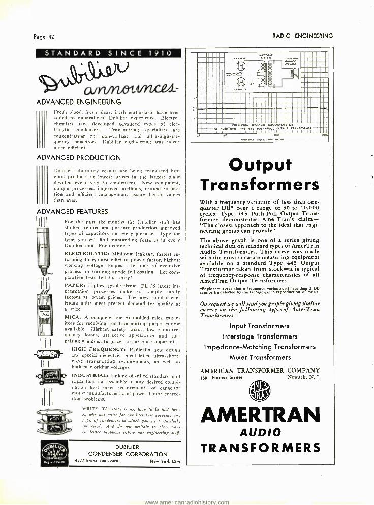
Page 42
S T A N D A R D S I N C E 1 9 1 0
ADVANCED ENGINEERING
Fresh blood, fresh ideas, fresh enthusiasm have been added to unparalleled Dubilier experience. Electro- chemists have developed advanced types of elec- trolytic condensers. Transmitting specialists are concentrating on high- voltage and ultra- high -fre- quency capacitors. Dubilier engineering was never more efficient.
ADVANCED PRODUCTION
Dubilier laboratory results are being translated into good products at lowest prices in the largest plant devoted exclusively to condensers. New equipment, unique processes, improved methods. critical inspec- tion and efficient management assure better values than ever.
ADVANCED FEATURES
VIII
H l'
0.145J1`Ì
For the past six months the Dubilier staff has studied, refined and put into production improved types of capacitors for every purpose. Type for type, you will find outstanding features in every Dubilier unit. For instance: ELECTROLYTIC: Minimum leakage, fastest re- forming time, most efficient power factor, highest working voltage, longest life, due to' exclusive process for forming anode foil coating. Let com- parative tests tell the story! PAPER: Highest grade tissues PLUS latest im- pregnation processes make for ample safety factors at lowest prices. The new tubular car- tridge units meet present demand for quality at a price.
MICA: A complete line of molded mica capac- itors for receiving and transmitting purposes now available. Highest safety factor, low radio -fre- quency losses, attractive appearance and sur- prisingly moderate price. are at once apparent.
HIGH FREQUENCY: Radically new design and special dielectrics meet latest ultra- short- wave transmitting requirements, as well as highest working voltages. INDUSTRIAL: Unique oil -filled standard unit capacitors for assembly in any desired combi- nation best meet requirements of capacitor motor manufacturers and power factor correc- tion problems.
WRITE! The story is too long to be told here. So why not write for our literature covering any /ypes of condensers in which you are particularly interested. And do not hesitate to place your condenser problems before our engineering staff.
DUBILIER CONDENSER CORPORATION
4377 Bronx Boulevard New York City
RADIO ENGINEERING
AMERTRAN
24SMlr, TYPE 443 !O -lS MIA
I - 1
ell DYNAMIC
O SPEAKER
? o r
i I o o o e
flS !El
II
o D=am-- AN - - FREQUENCY RESPONSE CHARACTERISTICS
OF AMERTRAN TYPE 443 PUSH PULL OUTPUT TRANSFORMER
Jo loo woo MOW
TREQIENCr CYCLES HER SECOND
Output Transformers With a frequency variation quarter DB* over a cycles, Type 443 Push former demonstrates "The closest approach neering genius can provide."
The above graph is technical data on standard Audio Transformers. with the most accurate available on a standard Transformer taken from of frequency- response AmerTran Output Transformers. *Engineers agree that a frequency cannot be detected by the average
On request we will send curves on the following Transformers -
Input Transformers
Interstage
Impedance- Matching
Mixer Transformers
AMERICAN TRANSFORMER 180 Emmet Street
AMER
AMERTRAN AUDIO
TRANSFORMERS
of less than one - range of 30 to 10,000
-Pull Output Trans- AmerTran's claim - to the ideal that engi-
one of a series giving types of AmerTran
This curve was made measuring equipment
Type 443 Output stock -it is typical
characteristics of all
variation of less than 2 DB ear in reproduction of music.
you graphs giving similar types of AmerTran
Transformers
Transformers
COMPANY Newark, N. J.
RAN
www.americanradiohistory.com

MAY, 1932
A SOLID BASE FOR BEAUTY
SANDING SEALER #5959
for
CABINET FINISHING
SANDING SEALER #5959 was created to fill an important re- quisite in cabinet finish. Beauty in woodwork surface depends on "the base," and #5959 has a high per- centage of solids to make a perfect foundation.
Smooth flowing, it builds and spreads evenly. It is easily sanded and most adaptable of all pyroxylin sealers on the market.
A demonstration is worth a volume of explanation about #5959. Call on our local representative who is
a furniture specialist and let him convince you.
"The Standard of Quality Since 1884"
THE ZAPON COMPANY A Subsidiary of Atlas Powder Company
Sta Ytford Connecticut
Page 43
CELLS DeVry Photo Electric Cells, designed primarily for motion picture work, possess a degree of sensitivity and an ionization point far in excess of any other cell now in use. Developed by a special process and protected by patents held by the Mcllvaine Patent Corporation, these cells are engineered to give the maximum response even to limited volumes of light.
Characteristics of the DeVry Photo Electric Cell
The DeVry Photo Electric Cell ionizes at from 130 to 180 volts, which accounts in part for its extra- ordinary life. At an average operating voltage of 90, these cells have a sensitivity of approximately 75 micro amperes per lumen, and operated at 10
points below the minimum ionization point they possess a sensitivity of approximately 140 micro amperes per lumen. These cells are made in a wide variety of styles to fit any application, and can be had both in argon and vacuum type.
HERMAN A. DeVRY, Inc. 55 E. Wacker Drive
Dept. R
CHICAGO, ILL.
FREE BULLETIN HERMAN A. DeVRY, INC., 55 E. Wacker Drive. Dept. R, Chicago, Illinois.
Please send me free bulletin containing complete characteristic curves, dimension chart, etc., on DeVry Photo Electric Cells.
Name
Address
Town State
www.americanradiohistory.com
Page 44
FOIL TIN
LEAD ALUMINUM
FOR CONDENSERS
43 YEARS MANUFACTURING EXPERIENCE IS YOUR GUARANTEE OF QUALITY MATERIAL AND SATISFACTORY SERVICE
STANDARD WIDTHS IN STOCK FOR PROMPT SHIPMENT
The Johnston Tin Foil & Metal Co. DEPT. RC 10
6016 -6160 S. BROAD \V \l' ST. LOUIS, MO.
EST. 1899 EASTERN OFFICE AND WAREHOUSE 1224 HALSEY ST. BROOKLYN, N. Y.
F. W. FLAD Representative Tel. JE 1549
RADIO ENGINEERING
IRIHIHNLD X FOG3 DEPENDABLE
DDIELI,CCsC4G30C
STRENGTH
When you specify "Molded from Resinox" on your purchase
order, you are assured of perfectly molded parts, of lustrous beauty, free from surface blemishes, strong
and durable, and of dependable dielectric quality.
RESINOX CORPORATION A SUBSIDIARY OF COMMERCIAL SOLVENTS CORPORATION
AND CORN PRODUCTS REFINING CO.
230 PARK AVENUE NEW YORK CITY
BOMBARDING Equipment capable of meeting all demands.
Fixtures and bombarding coils
for special applications.
High Frequency Furnaces Designers and builders of high frequency converters
for over 20 years.
LEPEL HIGH FREQUENCY LAB., INC.
39 WEST 60th STREET NEW YORK
MAGNET WIRE (Cotton or Silk). STRAND -Antennae (plain or enameled), Double Galvanized. WIRE
Antennae (plain or enameled); Con-
necting and Ground (Rubber covered, braided or plain). BUSS OR CON-
NECTING WIRES.
JOHN A. ROEBLING'S SONS CO. Trenton, N. J. Branches in Principal Cities
www.americanradiohistory.com

MAY, 1932
SM STRAITLINE EVI°S
NOT FOR PUBLICATION-
41
i
TÏInYíNiW!,N-`RaitL42(_.Cdnnirtsvé.. N,.1o24Z l.ic A Ma 0 Iiw+sFGxMCR.
f>.,rcF:Gly. .. 4w_.d,I45? ...
Ian ; Ifill;: 2.racr_ e4.. '!w I4th illl1l NlSI1&V7H J.
II11Ì iÖIIIRiuIIIII III °,, SEiRg 11 nppiltllllll illfil- Ì8BiIÌHPlim
S
Ifl ÌÌ ÌÚIIJ
t.".L'.
-BUT GOOD ENOUGH TO PRINT! The remarkably uniform curve shown above is typical of the new series of Straitline Audio Transformers and Reactors -less than half a decibel total variation from 30 to 12,000 cycles -more than "good enough" foi the highe:it quality broadcast and sound transmission systems!
Hand -wound and laboratory checked for performance -but reason- ably priced!
Write for specification sheets covering complete new line of "Straitline" transformers and prices.
ti1LVEII MARSIIALL, Inc. 6401 West 65th Street Chicago, U. S. A.
Export Division: 41 Water Street, New York City, U.S. A.
THE PROSPECTIVE CUSTOMER DEMANDS
GOOD CLEAR
9-I TONE SEVEN TONE ADJUST - MENTS . . . CONSTANT CAPACITY . . . MOIS- TURE PROOF ... RUG- GED CONSTRUCTION
ELIMINATES RE- SISTANCE STRIP. . . .
VERY COMPACT. . . .
HIGH VOLTAGE TEST. LIFE TEST UN-
EQUALED. PRICED RIGHT
ACTUAL SIZE
SOUND EXPERTS APPROVE The OCTAVE TONE CONTROL
A NEW TAPPED CONDENSER WITH SEVEN POSITIVE ADJUSTMENTS OF CAPACITY ELIMINATING THE RE- SISTANCE STRIP.
FREE SAMPLES SPECIFICATION
F:ILTERMATIC MFG. CO. HUNTING PARK AVE. AND MARSHALL ST. PHILADELPHIA PENNA.
Pagc 45
EASY AS
CUTTING PAPER
Set Manufacturers Have Standardized on KESTER SOLDER!
M AN U FACTURERS began build - ing better sets when they
began using Kester Solder. Kes- ter's self -contained flux is plastic rosin - it will not decompose because air and moisture are kept out. Kester plastic rosin flux is a non -conductor and it won't corrode. Purest virgin metals in Kester ... even exceed-
ing Class A purity requirements of the A.S.T.M. And lastly, Kester is as simple as it is safe
a cinch to use! Our Indus- trial Development Department stands ready to prepare a more active flux for the special cases that need it. Write now for our booklet, "Facts on Soldering." It's free!
Kester Solder Company, 4224 Wrightwood Ave., Chicago, Ill. Eastern Plant, Newark, N. J. Canada -Kester Solder Com- pany of Canada, Ltd., Brantford.
j(E STEM t' LUX' CORE SOLDER Acid -Core faste -Core Rosie -Core
easy to use
The Proved Condensers For Tuning
INTERMEDIATE TRANSFORMERS Specially tested Isolantite base mounts inside t ransformer shield. Self- aligning phosphor- bronze adjustable spring plates, double rivetted. Selected mica insulation. Proved design -will not change in resistance or capacity from humidity, temperature or vibration. Forty ranges in single or double models -10 to 2100 mmf.
Hammarlund presents also a brilliant new Midget Condenser, with Isolantite insulation. Single or dual -20 to 325 mmf. per section.
Mail Coupon for samples and quotations
4roH
ú0't- lltlteh Radio
PRODUCTS
' Jes ,ro .
0 v ò a óc
4çö ßm 4 Q e aae`
. S6 oroeoa 6' . .p 41 .. . .
;tFZO' r°ó`a SJscsg .'`tzs
www.americanradiohistory.com

. SALES ENGINEER A prominent a natactnrer of radio tubes requires th services e seices of a
Sales Engineer of proven ability. He must he possessed of a sound basic knowledge of receiving set circuits, and must be an able consultant in engineering phases of new circuit designs While not necessarily a tube engineer, a fundamental corking knowledge of Radio Tubes and their various applications is essential.
A reasonable knowledge of selling is highly desirable; the ability to intelligently present commercial angles is imperative. Personal character must be above reproach.
if you measure up to the foregoing qualifications, can provide veri- fication of favorable past experience, are willing to energetically, aggressively, and capably fulfill the duties of a Radio Sales E.ngi neer, you are invited to write us in detail. Your communication will he treated confidentially.
Members of our staff have been advised of this insertion. Kindly address your communication to Box 95, care of Radio Engineering, 19 East 47th St.. N. Y. C.
Page 46 RADIO ENGINEERING
An added SAFETY FACTOR !
Voltox has capacity for 6
to be enameled. can be it. Write for data.
Gilby Processed Carbonized Nickel For Plates Gilby Patented Selvage Mesh
VOLTOX (A Super Oxided Resistance Wire)
A new Gilby Product to 8 volts at a time. It is particularly suitable for potentiometer and rheostat winding. It appears worked into very close turns and is exceptionally elastic. Our engineers will tell you more about
G RE
6000 GILBY WIRE COMPANY
150 Riverside Ave., Newark, N. J.
Nickel -Chrome Resistance Wire Copper- Nickel Resistance Wire Nickel Wire and Sheet
ELMENCO
QUALITY PARTS FOR QUALITY PRODUCTS
RESISTORS CARBON
WIRE WOUND VITREOUS ENAMEL
STRIP AND FLEXIBLE
fi'Ef Condensers
BAKELITE
MICA PAPER
CARTRIDGE
ASK FOR SAMPLES Our years of experience, combined with best of engineering and manufacturing facilities have made us the leader in this field, and the choice of the most prominent Radio Manu- facturers.
Our Quality and Service are the Best Our Prices Will Satisfy You
ELECTRO-MOTIVE ENG. CORP.
NEW YORK
she hiA ftCY
LAKE PLACID, N.Y.
VACATION SPOT SUPREME!
Rolling mountains ... beau- tiful lakes ... boating ... swimming . . . riding . . .
dancing ... golf ... tennis . these and numerous
other attractions are offered by Lake Placid's only fire- proof hotel.
The Marcy American Plan
RATES TO FIT EVERY PURSE
®_SEra- ' : -t;L4 7 - _.;
(Ç OPHONE S ` OF ALL TYPES ...
SHURE Microphones are world- famous for their SENSITIVITY and true. natural TONE quality' This performance is attained by a combination of several features not to be found in any other microphone. You should have our catalog sheets with detailed specifications on file. Write today.
W /z4LCe / v2_ .L SILURE I3I OTHERS COMPANY
Monufocturers- Enffineers S. N. SHURE. Pres.
337 WEST MADISON ST. CHICAGO, ILLINOIS
www.americanradiohistory.com

MAY, 1932 Page 47
ondensers.. FILTER » BY -PASS » IGNITION » TELEPHONE » TELEGRAPH COILS » TRANSFORMERS » HOOK -UP WIRE !All types of braided "Push -back" wire, spe - 2
Il ri:r for \ o. Rodio-Industrial Catalog on your cool pony letter á00d ì cially processed for high insulation resistance../
Kellogg Switchboard and Supply Company 1066 West Adams Street ... CHICAGO, ILLINOIS
MEASURE CAPACITANCE » » » SPEED & ACCURACY « « «
FOR CONVENIENCE, SPEED, AND ACCURACY IN THE MEASUREMENT OF CAPACITANCE, THERE IS NOTHING THAT CAN EQUAL A WELL DE-
SIGNED BRIDGE. GENERAL RADIO HAS A COM-
PLETE LINE OF CAPACITY BRIDGES OF VARIOUS
TYPES, WITH THE TYPE 240 CAPACITY METER AS A GENERAL -PURPOSE INSTRUMENT.
THE TYPE 240 CAPACITY METER COVERS THE RANGE BETWEEN 11.1 MICROFARADS AND 1000
MICROMTCROFARADS WITH AN ACCURACY OF ABOUT 0.3 %. IT MEASURES POWER FACTOR AS
WELL AS CAPACITANCE, ONE MEASUREMENT GIVING NOT ONLY THE SIZE OF THE CON- DENSER UNDER TEST BUT ITS LOSSES AS WELL.
WE RECOMMEND THIS BRIDGE FOR TESTING AND INSPECTION WORK OF ALL KINDS. WRITE FOR DATA. ITS PRICE IS $81.00.
GENERAL RADIO COMPANY CAMBRIDGE, MASSACHUSETTS
LAMINATIONS for Audio & Power Transformers
SPECIALIZED METHODS - YEARS OF EXPERIENCE
E
Wide Variety of Stock Standard Sizes Dimension and Price Sheets on request
We Also Make PERMANENT MAGNETS- DIES -TOOLS-
METAL STAMPINGS Facilities for prompt service
Thomas& Skinner /100 to I/20 E.Twen y -Third St. Steel Products Co. INDIANAPOLIS, INO.
Volume Indicator Panel
For Broadcast Speech Input Systems, Recording and Public Address Installations. Rectifier type, laboratory calibrated with
Range -16 DB to +32 DB
Mounted on Standard 19" x 7" x %" Black Enameled Aluminum Panel. Price in U. S. A. net f.o.b. Chicago (Code LISPS) $80.00
Send for Bulletin 8C
JENKINS & ADAIR, INC. ENGINEERS
CHICAGO, U. S. A. Cable Address: JENKADAIR
Phone: Keystone 2130 3333 Belmont Avenue British Offices: 76 Old Hall Street, Liverpool
40 Buckingham Gate, London, S.W. 1 French Office: 10 Rue de Chateaudun, Asnieres Mexican Office: Av. 5 de Mayo 10, Mexico, D. F. Indien Offices: Ismail Bldg., Homby Road. Fortn, Bombay
43/1 D Dharamtola Street, Calcutta Japanese Office: 9 Mlneml- Sumiye- Machl, Osaka Chinese Office: 20 Nanking Road, Shanghai
°:VIII!I IIIIIIIIIIIIIIIIIIIIIIIIIIIIIIIII IIIIIIIIIIIIII111111IIIIIIIIIIIIIIII II H
PHOTO ELECTRIC CELLS MOST SENSITIVE AND POWERFUL
ON THE MARKET Cetron Cells are made by a totally different process for making caesium argon cells - licensed under patents and applications of the Mellvaine Patent Corporation. These cells not only have the highest ionization point, but. the greatest reliability as well, and are noted for their extremely long life. Used extensively for motion picture, television and other appli- catit.ns.
Interesting Data for Reliable Distributors. CONTINENTAL ELECTRIC CO.
ST. CHARLES, ILLINOIS
TRU -VAC VACUUSf GAUGES =
will give you readings on an electric meter of exact pressures and microns of water, vapor gases and air in any vacuum system. FACTORY REPRESENTATIVES WANTED E
d1111111111111111111111111111111111111 111111111111111111111 IIIIIIIIII IIIIIIIIIIIIIIIIIIIIIIIIIIIIIIIIIIIIIIIÌIIIIIIIIIIIIIIil11111111111111111111111111111111111111111111111111111171 :11111111111111114
www.americanradiohistory.com
Page 48 RADIO ENGINEERING
extolite Laminated PUNCHING -MACHINING
Sheets - Rods - Tubing All sizes carried in stock
GENERAL FABRICATING COMPANY 37 East 18th Street, New York City
A
"GENERAL ELECTRIC" PRODUCT
OUR PROMPT SERVICE -is a valuable asset in co -ordi- nating your production work.
t MIDWEST CONDENSER
MICROPHONES Specifications of suspension model No. 150:
TUBES -2 type 864
OUTPUT LEVEL -Minus 25db. OUTPUT IMPEDANCE -200 or 50 ohms
UNIFORM RESPONSE -30 to 10,000 cycles PHYSICAL DIMENSIONS -31/4" in diameter
II" in height
REVOLVING SWIVEL HEAD
Remarkably low price. ii. 7
MIDWEST BROADCAST EQUIPMENT COMPANY 6007 Diversey Avenue Chicago, III.
WAXES, COMPOUNDS a n d V A R N I S H E S
for insulation of condensers transformers, coils. power packs, pot heads, sockets, wiring devices. wet nd dry batteries, etc.... WAX SATURATORS for braided wire and tape. WAXES for radio parts.... Compounds made to your own specifications If you prefer.
ZOPHAR MILLS, INC. Court and Lorraine Streets Founded 1846 Brooklyn, N. Y.
PIEZO -ELECTRIC CRYSTALS Since 1925 we have been recognized as the RELIABLE PRO- DUCERS of POWER CRYSTALS. We are at your service to supply your needs. Special prices for quantity lots. Your request will bring our price list.
SCIENTIFIC RADIO SERVICE "The Crystal Specialists"
124 Jackson Avenue, University Park, Hyattsville, Maryland
Irl Dual Ratio Dial for All -Wave Sets
WRITE FOR SAMPLE AND PRICES Eddie Mfg. Co., 9 W. Illinois St., Chicago
PROTECT Those INSTRUMENTS Littelfuses afford complete pro - Also Radio Receiver and Am- tection for voltmeters, milliam- plifier Littelfuses, and High meters, tube testers, etc. Range Voltage Littelfuses for trans. in size from 1 /100 to 2 amps. milting tubes, rectifiers, oscille - capacity. tors. etc.
Write for instructive catalog. LITTELFUSE LABORATORIES
1778 WILSON AVE. CHICAGO. U. S. A.
,,,,,r LITTELFUSES bort circuit"
BRASS -BRONZE -COPPER NICKEL SILVER -ZINC PHOSPHOR BRONZE
In Gauges .001 and Thicker. 1/16" to 16" Wide
HOT TIN COATED METALS IN COILS AND STRIPS
THE BALTIMORE BRASS CO. 1206 WICOMICO ST., BALTIMORE, MD.
NICKEL CUT
For Radio Tubes between .070 and .006 dia.
±.002 " -no burrs -every piece straight Capacity 10,000.000 pieces daily
Small metal parts to your blue print. 100 to 675,000 pieces per lb.
FLAT ENDS
Art Wire and Stamping Company 18 -22 Boyden Place, Newark, N. J.
When You Renew Your Subscription to RADIO ENGINEERING
Remember the Group Rate -$1.00 a year for four or more subscriptions.
Regular Rate -$2.00 a year in U. S. A. -$3.00 in foreign countries
CONDENSER PAPER 182 Cornelison Ave. Mills at Newark Ave. Jersey City, N. J. Elizabeth, N. J.
PETER J. SCHWEITZER, Inc., 200 Fifth Ave. New York
COILS Choke -Impedance- - Magnet-Transformer
TRANSFORMERS Audio -B -Power Unit -Broadcast Station -Output
Filament Heating -Power- Stepdown Have us quote to your specification
POWER TRANSFORMER CO., 36 E. 22nd St., New York City
PRESS DOWN
/HERE
FAHNESTOCK CLIPS Standard in the Radio Industry
Made in 58 Sizes and Shapes Send for Samples and Prices
FAHNESTOCK ELECTRIC COMPANY -Long Island City, N. Y.
www.americanradiohistory.com

MAY, 1932
THERE 4PRO
Page 49
IS A DIFFERENCE!
" T H E S T A
har all p r.tctical purposes, transmitting condensers may he divided into two classes, those that are BUILT FOR TRANSMITTING and those that merely LOOK as though they were. The name CARDWELL on a transmitting condenser dispels any doubt as to the class to which it belongs. There are many CARDWELL condensers BUILT FOR TRANSMITTING. They range from small condensers in many capacities to giant condensers for high powered installations. 'l'here is nothing of the shrinking violet about CARDWELL receiving condensers either. They are BUILT FOR SERVICE and look it.
Send for literature TIIE ALLEN D. CARDWELL MFG. CORF'N. 91 Prospect Street Brooklyn, N. Y.
CARDWELL CONDENSERS A N D M A N U F A C T U R I N G S E R V I C E
N D A R D O F C O M P A R I S O N "
Recording on Metal If you are interested in this new and profitable branch of Radio, get your name on our mailing list for our new bulletin describing our Crystal cutting head and complete recorders.
Astatic Microphone Laboratory
21 Olive Street, Youngstown, O.
LANDOHMS ARMOURED WIRE WOUND RESISTORS WILL LOWER YOUR COSTS -May we sample and quote
The Muter Company 1255 S. Michigan Ave. CHICAGO, ILL.
MICROPHONE REPAIRS You may now have the expert services of our laboratories for
the repair of Microphones of any make. A 24 to 48 -hour schedule
is maintained to enable you to get your equipment back without loss of time. All work is fully guaranteed. Prices very reasonable. Write for our quotation stating type of microphone and descrip- tion of what is wrong with the unit.
Try this servire nos. It saves you rime and money!
SHURE BROTHERS COMPANY Manufacturers -Engineers
S.N. SHURE. Pres.
337 WEST MADISON ST CHICAGO, ILLINOIS
TELEPHOTO CAESIUM ARGON PHOTOELECTRIC CELLS
Pamphlet on reauest
Highly sensitive, Telephoto cells reduce the amount of amplifica- tion required for tonal reproduc- tion, obviating to a remarkable extent the possibility of distortion . . . the results of painstaking supervision in each detail of con- struction, of rigid adherence to high and scientific standards of achievement. Telephoto cc;ls are guaranteed to last 6 months.
TELEPHOTO & TELEVISION CORPORATION
133 -135 West 19th St. New York
1922 GATES AMPLIFIERS 1922
FOR THEATRES. BROADCASTING STATIONS & ADDRESS SYSTEMS
GATES RADIO & SUPPLY CO. 1932 QUINCY. ILLINOIS. U. S. A. 1932
WE offer to manufac- turers interested. in
EXPORT the services of a dependable organization, well established in the entire foreign field.
AD. AURIIEMA9 INC. Manufacturers' Export Managers
116 Broad Street, New York, N. Y.
Rocke International Electric Corp. 15 Laight Street, New York City
Export Managers Radio -sound equipment -Electric Products AL ®
www.americanradiohistory.com

Page 50
NEW UNITED SCIENTIFIC LAB.
VARIABLE CONDENSER
This new type "D" Condenser is designed to meet the com- mercial requirements of all types of present day receivers. All coupling effects have been eliminated and accurate tuning adjustment of all sections is assured. Other exclusive features make this condenser the outstanding tuning unit, measuring up fo the rigid standards of the United Scientific Laboratories.
Available in clock or counter -clock wise rotation with trim- mers, in one, two or three gang units in capacities from .00015 to .00042 MFD.
Write for circular giving full specifications. Let us quote on your particular requirements.
United Scientific Laboratories, Inc. 62 WEST 14th ST. NEW YORK CITY
RADIO ENGINEERING
DEPENDABLE QUALITY- UNIFORMITY
SERVICE ON
WAXES -&- MELTABLE INSULATING and WEATHER-
PROOFING COMPOUNDS WAXES -All kinds.
IMPREGNATIONS -Condensers, Coils, Rubber - Covered and Weather -Proofed Wire, Telephone and Electrical Cables, Etc.
SEALING COMPOUNDS -Coils, Condensers, Batteries (Wet & Dry), Pot Heads, Cables, Wir- ing Devices and Specials.
FINISHING -All grades of Weather Proof and Rubber -Covered Wire.
SPECIAL COMPOUNDS
35th St. & Maplewood Ave. Chicago, Ill.
"For over 35 yrs."
INDEX OF ADVERTISERS A
Acme Wire Co., The 46 Ad. Auriema. Inc 49 American Transformer Co 42 Arcturus Radio Tube Co.... Second Cover Art Wire & Stamping Co 48 Asiatic Microphone Lab 49
B
Bakelite Corp Back Cover Baltimore Brass Co., The 48
C
Candy & Co 50 Cardwell Mfg. Co.. Allen D 49 Central Radio Laboratories 41 Chicago Telephone Supply Co 8 Condenser Corp. of America 52 Continental Electric Co 47 Crowe Name Plate & Mfg. Co..Third Cover
D
DeVry, Inc., Herman A 43 Dubilier Condenser Corp 42
E
Eddie Manufacturing Co 48 Electro- Motive Engineering Corp 46
I Fahnestock Electric Co 48 Filtermatic Mfg. Co 45 Frost, Inc., Herbert H 8
G
Gates Radio & Supply Co General Electric Co General Fabricating Co General Plastics, Inc General Radio Co Gilby Wire Co Gray bar Electric Co
II
Hammarlund Mfg. Co
Inca Manufacturing Division International Broadcasting Equip. Co
J Jenkins & Adair. Inc Jewell Electric Instrument Co Johnston Tin Foil & Metal Co., The
K
Kellogg Switchboard & Supply Co Kester Solder Co
L Lepel High Frequency Lab., Inc Littelfuse Laboratories LuxTron Mfg. Co., Inc
M
Midwest Broadcast Equipment Co Muter Company, The
49 12 48
1 47 46 33
45
9 10
47 52 44
47 45
44 48 51
48 49
D
Ohio Carbon Co, The
Parker -Kalon Corp. Phelps Dodge Copper Products Corp Pines Winterfront Co Power Transformer Co
R
RCA Radiotron Co.. Inc RCA Victor Co., Inc Resinox Corporation Rocke International Electric Corp Roebling's Sons Co.. John A Rola Company, The
s Schweitzer, Peter J.. Inc Scientific Radio Service Shakeproof Lock Washer Co Shure Brothers Co 46, Silver -Marshall, 1nr
T Telephoto & Television Corp Thomas & Skinner Steel Products Co Thordarson Electric Mfg. Co
U
United Scientific Laboratories
W Western Electric Co White Dental Mfg. Co., The.. S.
Z
Zapon Company Zophar Mills, Inc
33
5 9
39 48
3 7
44 49 44 35
48 48 11 49 45
49 47 41
50
36 39
43 48
www.americanradiohistory.com

MAY, 1932 Page 51
THE Group Subscription Plan for RADIO ENGINEERING enables a group of engineers or department heads to subscribe at one -half the usual yearly rate.
The regular individual rate is $2.00 a year. In groups of 4 or more, the subscription rate is $1.00 a year. (In Canada and foreign countries $2.00.)
The engineering departments of hundreds of manufacturers in the radio and allied industries have used this Group Plan for years, in renewing their sub- scriptions to RADIO ENGINEER- ING.
Each subscriber should print his name and address clearly and state his occupation - whether an executive, engineer, department head, plant super- intendent, or foreman, etc.
Remember this Group Plan when Your Subscription Expires
(Radio Engineering)
Bryan Davis Publishing Co, Inc. 19 East 47th Street New York, N. Y.
Los Angeles Chicago Cleveland
ACME WIRE PRODUCTS
All ACME products are made to recognized commercial standards, including those of :
Nat'l Electric Mfrs. Assn. Radio Manufacturers' Assn. Amer. So. for Testing Materials.
Also
For over
THE
Magnet Wire (All Insulations)
Parvolt Condensers (Filter and By -Pass)
Condensers for Power Factor Correction
Coils, Magnet Wire Wound Varnished Insulations (Cambric, Paper, Silk, Tape)
Aerial Wire (Stranded and Solid)
25 years, suppliers to the largest radio and electrical manufacturers.
ACME WIRE CO. New Haven, Conn.
AT
LOW COST for EXPERIMENTAL
AND COMMERCIAL APPLICATIONS The LuxTron "ST" Cell requires no amplification. It operates at 221/2 volts. With a 40 watt frosted lamp at 12" it gises a minimum of 2 milliamps photo- potential. It is the lowest priced practical photo cell on the market. The ideal photo cell for thousands of experimental and commercial uses. 'Every LusTron cell is photometrically tested and fully guaranteed.
"ST" Cell Priced at $3.50 'l'he í.uxTron "R-1" Relay will handle 110 volts, 1 amp., with- out arcing or sparking. It is designed especially for use with the LuxTron "ST" Cell. Positive and rapid in its action. No amplifier needed. The "R -1" type Relay is priced at 54.00 (less case). I.uxTron engineers are prepared to give expert advice on all phases of the light- control art. SEND FOR INTERESTING LITERATURE ON LUX T RON
CELLS .4ND RELAYS
LUXTRON MFG. CO., INC. Pioneers in )'hotu Cell Devices Since 1900
241 Lafayette Street Dept. RE New York, N. Y.
www.americanradiohistory.com
Page 52 RADIO ENGINEERING
A Complete Service!
Instruments Plus
Application Engineering
Jewell Master Portables
i
High resistance direct cur- rent voltmeters, capacity meters, and ohmmeters are available in addition to the standard A. C., D. C., and thermocouple indicating in- struments. Sturdy molded bakelite cases of uniform size and easy -to -read mirror type scales of 4 -7/16 inch lengths are two reasons for their wide usage in laboratory and pro- duction testing.
Jewell Pocket Portables Unusually long mirror type scales
are available in these compact instru- ments. Direct current and thermo- couple types are provided in single and multiple range instruments with range combinations to meet every measuring need. Also offered as an ohmmeter with self- contained battery and compensator for battery voltage change.
ENGINEERS for the last word in condenser design and construction
SPECIFY the new ACRACON SEMI -DRY
ELECTROLYTIC UNIT
ACRACON 8-8 MFD 500 PFRK
TYPE D M cc OF A
Jewell Panel Instruments A complete selection of panel mount-
ing instruments ranging from 434 Inches to 2r/ inches case diameter. The 234 inch bakelite case line offers A. C., D. C., rectifier type A. C. current, and thermo- couple type high frequency instruments that are interchangeable in the same mountings.
The movements used in these instru- ments have stamina proven by years of service in such applications as arc welders, airplane control panels, and radio service equipment, where the most severe conditions are encountered.
Jewell Engineering Service The specialized skill and experience of Jewell instrument
engineers are instantly available without obligation to assist in any design problem involving electrical measuring in- struments. Get in touch with your local Jewell representa- tive or the Jewell factory.
Jewell Electrical Instrument Company 9 Haynes Avenue, Newark, New Jersey
32 YEARS MAKING INSTRUMENTS EWEL
Note These Features:
peak operating voltage 500
surge voltage 600
low initial leakage
leakage current at 500 volts less than .2 mils per mfd.
constant capacity; does not decrease with age
stable power factor; does not increase with age
non -corrosive connections
metal or fibre container
standard and special sizes
WRITE TODAY FOR DE-
SCRIPTIVE LITERATURE!
*Acracon Features Are Protected by Patents Pending
CONDENSER CORP. of AMERICA 259 Cornelison Ave., Jersey City, N. J.
Factory Representatives in:
Chicago Cincinnati San Francisco St. Louis Los Angeles Toronto
And Other Principal Cities
www.americanradiohistory.com

--- 50
Ìo
No. 90 (Base number)
Made With Any Type of Scale
Fan Type, Full
Either 180 180 degree (Traveling Light)
or 60 Degree. (Flat or Angled
Back)
NO.90 TWO IEED WEDGE DRIVE TUNING CONTROL
From Fast to Slow at a Finger's Touch
MOVING the thumb lever to the right gives a 6 to 1
ratio. When thrown to the left affords a 30 to 1 ratio, both ratios in 180 degrees.
An ideal control for combination Broadcast and Short Wave Sets or for accurate Short Wave work of any sort. Valuable on superheterodynes when fine tuning is desirable.
Scales of the fan type are in various sizes and multi- channel calibrations in kilocycles or megacycles are made to order.
When writing furnish definite specifications as to scale, direction of reading and size of condenser shaft.
Patent :1 ',plied
Illustrations full size
(ROWE GNRIAMik PLATE & MAN UFAÇTURING 10.
www.americanradiohistory.com

In the Broadcasting Station .... insulations must be dependable
ON THE AIR, often from six in the morning until three the next, broad- casting equipment must be depend- able. Overcrowded ether channels require apparatus that is extremely accurate in performance. The de- pendability and accuracy of most of this equipment depends upon the efficiency of its insulations. That is whyBakeliteMaterials are so widely used in broadcasting stations.
Bakelite Laminated provides de- pendable insulation for the Roller Smith contactor shown above. The base, separators and bushings of
'BAKELITE CORPORATION, 2.47 I
BAKELITE CORPORATION OF
Contactor made by Roller Smith Company, New York City
this 5 ampere, 3000 volt device are made of strong insulating Bakelite Laminated. Moisture will not im- pair this material's insulating effici- ency nor will hard wear or chance blows destroy it.
Whether in the Molded, Laminated or Varnish form, Bakelite Materials possess ideal properties for use as insulating materials in the elec- tronics industry. Strong, highly insulating, non -corrodible and non- hygroscopic - these materials give constant and dependable service for a long period of time. We invite
you to avail yourself of the assistance of our laboratories and engineers.
Write for illustrated booklet 12L, "Bakelite La mi nated", which further describes this material -its proper- ties and uses.
'ark Avenue, New York, N. Y...635 West Twenty- Second Street, Chicago, I11.
CANADA, LIMI'l'1:D, 168 Dof' fort o S , Toronto, Ontario, Canada
BAK. T H E M A T E R I A L
LITE O F A T H O U S A N D U S E S
www.americanradiohistory.com