the iSCSI protocol.
134
CHAPTER 40-1 Cisco Prime DCNM SAN Client Online Help 40 Configuring iSCSI Cisco MDS 9000 Family IP storage (IPS) services extend the reach of Fibre Channel SANs by using open-standard, IP-based technology. The switch allows IP hosts to access Fibre Channel storage using the iSCSI protocol. Note The iSCSI feature is specific to the IPS module and is available in Cisco MDS 9200 Switches or Cisco MDS 9500 Directors. The Cisco MDS 9216i switch and the 14/2 Multiprotocol Services (MPS-14/2) module also allow you to use Fibre Channel, FCIP, and iSCSI features. The MPS-14/2 module is available for use in any switch in the Cisco MDS 9200 Series or Cisco MDS 9500 Series. Note For information on configuring Gigabit Ethernet interfaces, see “Configuring Gigabit Ethernet Interface” section on page 43-5. This chapter includes the following topics: • Information About iSCSI section, page 40-2 • Licensing Requirements for iSCSI section, page 40-32 • Guidelines and Limitations section, page 40-32 • Default Settings section, page 40-33 • Configuring iSCSI section, page 40-34 • Configuring iSLB section, page 40-54 • Distributing the iSLB Configuration Using CFS section, page 40-66 • Configuring iSCSI Authentication section, page 40-70 • Creating an iSNS Client Profile section, page 40-74 • Configuring iSNS Cloud Discovery section, page 40-78 • Verifying iSCSI Configuration section, page 40-81 • Configuration Examples for iSCSI section, page 40-103 • Field Descriptions for iSCSI section, page 40-125 • Additional References section, page 40-133
Transcript of the iSCSI protocol.
C H A P T E R 40
Configuring iSCSICisco MDS 9000 Family IP storage (IPS) services extend the reach of Fibre Channel SANs by using open-standard, IP-based technology. The switch allows IP hosts to access Fibre Channel storage using the iSCSI protocol.
Note The iSCSI feature is specific to the IPS module and is available in Cisco MDS 9200 Switches or Cisco MDS 9500 Directors.
The Cisco MDS 9216i switch and the 14/2 Multiprotocol Services (MPS-14/2) module also allow you to use Fibre Channel, FCIP, and iSCSI features. The MPS-14/2 module is available for use in any switch in the Cisco MDS 9200 Series or Cisco MDS 9500 Series.
Note For information on configuring Gigabit Ethernet interfaces, see “Configuring Gigabit Ethernet Interface” section on page 43-5.
This chapter includes the following topics:
• Information About iSCSI section, page 40-2
• Licensing Requirements for iSCSI section, page 40-32
• Guidelines and Limitations section, page 40-32
• Default Settings section, page 40-33
• Configuring iSCSI section, page 40-34
• Configuring iSLB section, page 40-54
• Distributing the iSLB Configuration Using CFS section, page 40-66
• Configuring iSCSI Authentication section, page 40-70
• Creating an iSNS Client Profile section, page 40-74
• Configuring iSNS Cloud Discovery section, page 40-78
• Verifying iSCSI Configuration section, page 40-81
• Configuration Examples for iSCSI section, page 40-103
• Field Descriptions for iSCSI section, page 40-125
• Additional References section, page 40-133
40-1Cisco Prime DCNM SAN Client Online Help
Chapter 40 Configuring iSCSIInformation About iSCSI
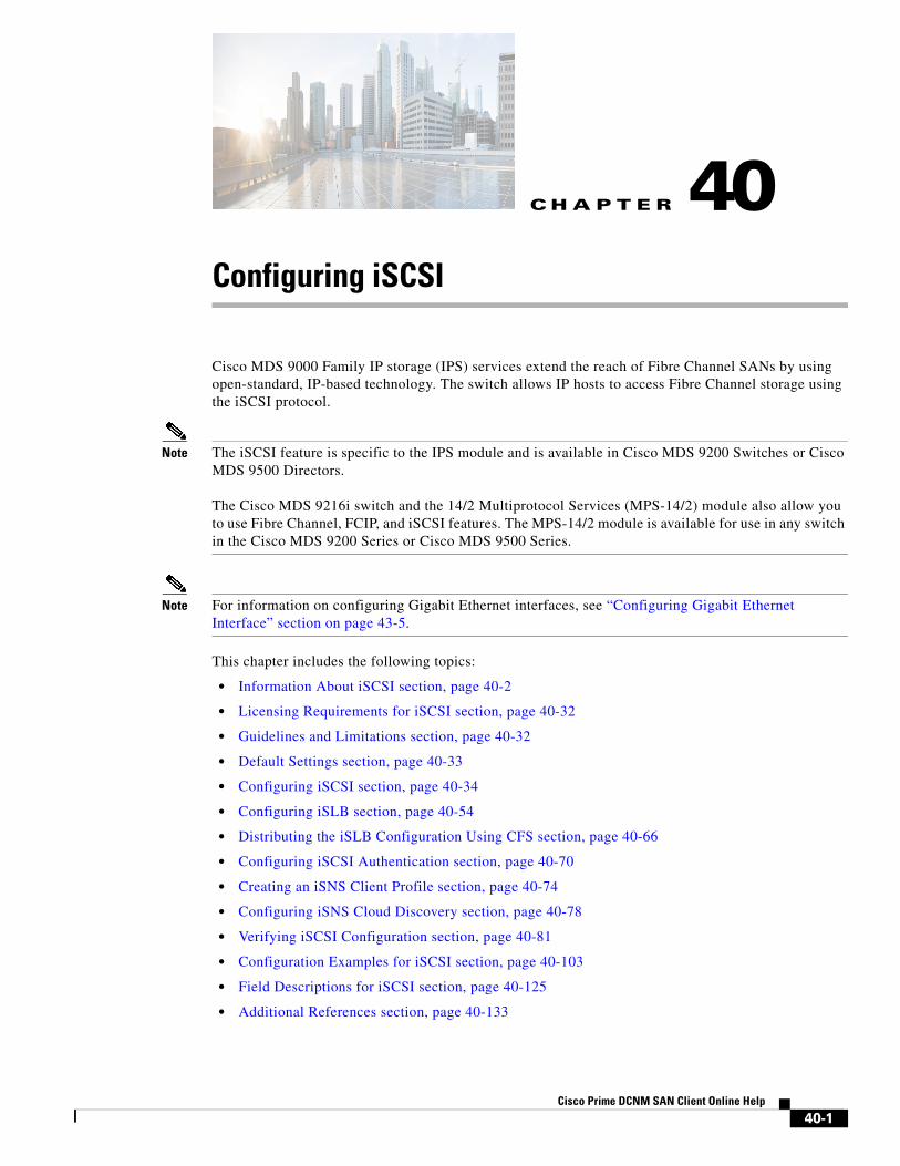
Information About iSCSICisco MDS 9000 Family IP Storage (IPS) services extend the reach of Fibre Channel SANs by using open-standard, IP-based technology. The iSCSI feature consists of routing iSCSI requests and responses between iSCSI hosts in an IP network and Fibre Channel storage devices in the Fibre Channel SAN that are accessible from any Fibre Channel interface of the Cisco MDS 9000 Family switch. Using the iSCSI protocol, the iSCSI driver allows an iSCSI host to transport SCSI requests and responses over an IP network. To use the iSCSI feature, you must explicitly enable iSCSI on the required switches in the fabric.
Note The iSCSI feature is not supported on the Cisco Fabric Switch for HP c-Class Bladesystem and Cisco Fabric Switch for IBM BladeCenter.
The iSCSI feature consists of routing iSCSI requests and responses between iSCSI hosts in an IP network and Fibre Channel storage devices in the Fibre Channel SAN that are accessible from any Fibre Channel interface of the Cisco MDS 9000 Family switch (see Figure 40-1).
Figure 40-1 Transporting iSCSI Requests and Responses for Transparent iSCSI Routing
Each iSCSI host that requires access to storage through the IPS module or MPS-14/2 module needs to have a compatible iSCSI driver installed. Using the iSCSI protocol, the iSCSI driver allows an iSCSI host to transport SCSI requests and responses over an IP network. From the host operating system perspective, the iSCSI driver appears to be an SCSI transport driver similar to a Fibre Channel driver in the host.
The IPS module or MPS-14/2 module provides transparent SCSI routing. IP hosts using the iSCSI protocol can transparently access targets on the Fibre Channel network. It (see Figure 40-1) provides an example of a typical configuration of iSCSI hosts connected to an IPS module or MPS-14/2 module through the IP network access Fibre Channel storage on the Fibre Channel SAN.
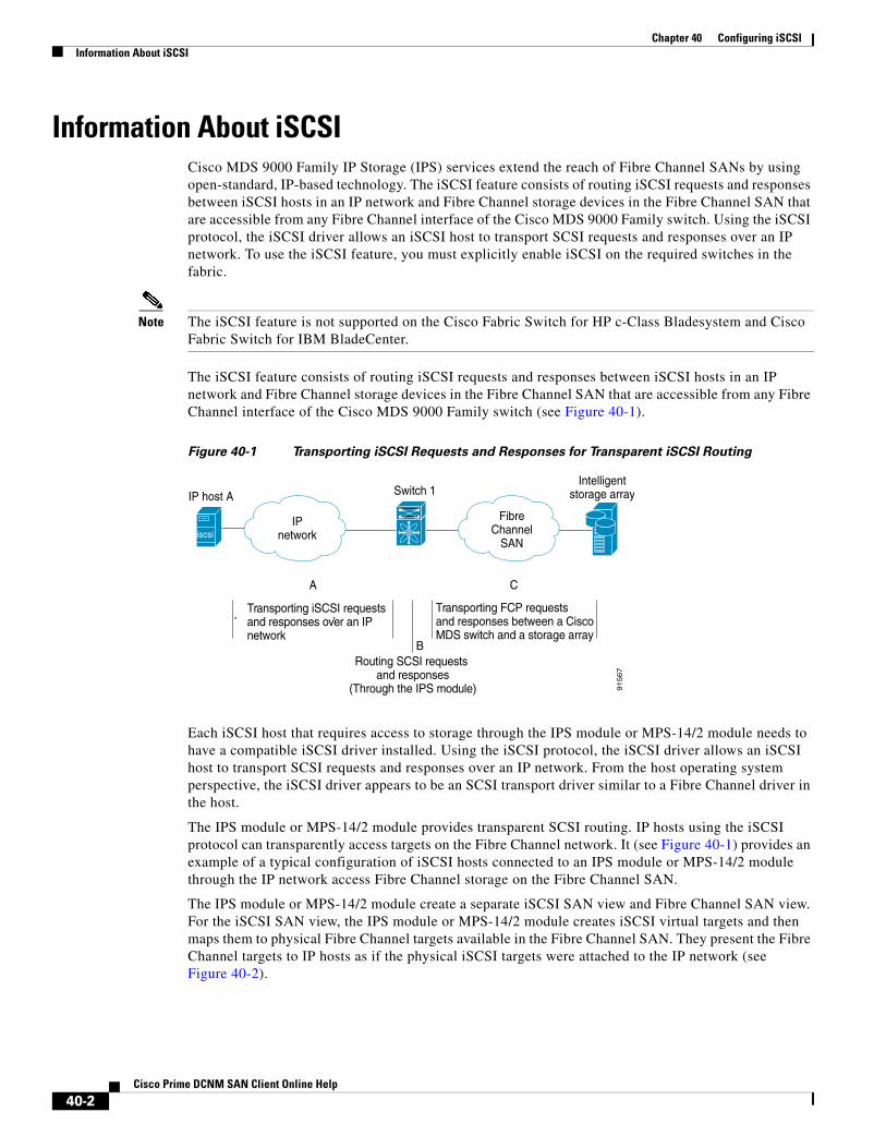
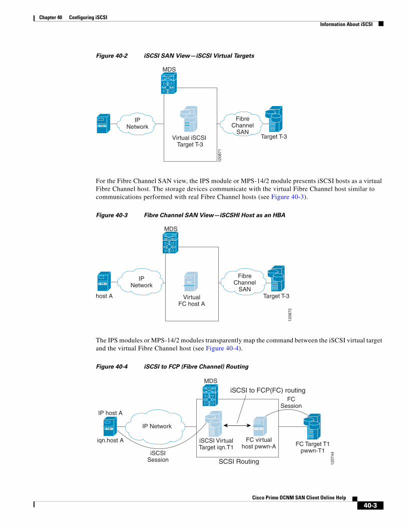
The IPS module or MPS-14/2 module create a separate iSCSI SAN view and Fibre Channel SAN view. For the iSCSI SAN view, the IPS module or MPS-14/2 module creates iSCSI virtual targets and then maps them to physical Fibre Channel targets available in the Fibre Channel SAN. They present the Fibre Channel targets to IP hosts as if the physical iSCSI targets were attached to the IP network (see Figure 40-2).
Switch 1
Transporting iSCSI requestsand responses over an IPnetwork
IPnetwork
FibreChannel
SAN
IP host AIntelligent
storage array
A C
BRouting SCSI requests
and responses(Through the IPS module)
Transporting FCP requestsand responses between a Cisco MDS switch and a storage array
91
56
7
iscsi
40-2Cisco Prime DCNM SAN Client Online Help
Chapter 40 Configuring iSCSIInformation About iSCSI
Figure 40-2 iSCSI SAN View—iSCSI Virtual Targets
For the Fibre Channel SAN view, the IPS module or MPS-14/2 module presents iSCSI hosts as a virtual Fibre Channel host. The storage devices communicate with the virtual Fibre Channel host similar to communications performed with real Fibre Channel hosts (see Figure 40-3).
Figure 40-3 Fibre Channel SAN View—iSCSHI Host as an HBA
The IPS modules or MPS-14/2 modules transparently map the command between the iSCSI virtual target and the virtual Fibre Channel host (see Figure 40-4).
Figure 40-4 iSCSI to FCP (Fibre Channel) Routing
iSCSIiSCSI
MDS
1208
71
IPNetwork
Virtual iSCSI Target T-3
Target T-3
FibreChannel
SAN
FC
MDS
1208
72
VirtualFC host A
Target T-3
iSCSIiSCSI
host A
IPNetwork
FibreChannel
SAN
iSCSIiSCSI iSCSIiSCSI
IP host A
iqn.host A
MDS
IP Network
FC virtualhost pwwn-A
iSCSI VirtualTarget iqn.T1 FC Target T1
pwwn-T1
SCSI Routing 1207
44
iSCSI to FCP(FC) routing
iSCSISession
FCSession
40-3Cisco Prime DCNM SAN Client Online Help
Chapter 40 Configuring iSCSIInformation About iSCSI
Routing SCSI from the IP host to the Fibre Channel storage device consists of the following main actions:
• The iSCSI requests and responses are transported over an IP network between the hosts and the IPS module or MPS-14/2 module.
• The SCSI requests and responses are routed between the hosts on an IP network and the Fibre Channel storage device (converting iSCSI to FCP and vice versa). The IPS module or MPS-14/2 module performs this conversion and routing.
• The FCP requests or responses are transported between the IPS module or MPS-14/2 module and the Fibre Channel storage devices.
Note FCP (the Fibre Channel equivalent of iSCSI) carries SCSI commands over a Fibre Channel SAN.Refer to the IETF standards for IP storage at http://www.ietf.org for information on the iSCSI protocol.
About iSCSI Configuration LimitsiSCSI configuration has the following limits:
• The maximum number of iSCSI and iSLB initiators supported in a fabric is 2000.
• The maximum number of iSCSI and iSLB initiators supported is 200 per port.
• The maximum number of iSCSI and iSLB sessions supported by an IPS port in either transparent or proxy initiator mode is 500.
• The maximum number of iSCSI and iSLB session support by switch is 5000.
• The maximum number of iSCSI and iSLB targets supported in a fabric is 6000.
Presenting Fibre Channel Targets as iSCSI TargetsThe IPS module or MPS-14/2 module presents physical Fibre Channel targets as iSCSI virtual targets, allowing them to be accessed by iSCSI hosts. The module presents these targets in one of the two ways:
• Dynamic mapping—Automatically maps all the Fibre Channel target devices/ports as iSCSI devices. Use this mapping to create automatic iSCSI target names.
• Static mapping—Manually creates iSCSI target devices and maps them to the whole Fibre Channel target port or a subset of Fibre Channel LUNs. With this mapping, you must specify unique iSCSI target names.
Static mapping should be used when iSCSI hosts should be restricted to subsets of LUs in the Fibre Channel targets and/or iSCSI access control is needed (see the “iSCSI Access Control” section on page 40-11). Also, static mapping allows the configuration of transparent failover if the LUs of the Fibre Channel targets are reachable by redundant Fibre Channel ports (see the “Transparent Target Failover” section on page 40-23).
Note The IPS module or MPS-14/2 module does not import Fibre Channel targets to iSCSI by default. Either dynamic or static mapping must be configured before the IPS module or MPS-14/2 module makes Fibre Channel targets available to iSCSI initiators.
40-4Cisco Prime DCNM SAN Client Online Help

Chapter 40 Configuring iSCSIInformation About iSCSI
Dynamic Mapping
When you configure dynamic mapping the IPS module or MPS-14/2 module imports all Fibre Channel targets to the iSCSI domain and maps each physical Fibre Channel target port as one iSCSI target. That is, all LUs accessible through the physical storage target port are available as iSCSI LUs with the same LU number (LUN) as in the physical Fibre Channel target port.
The iSCSI target node name is created automatically using the iSCSI qualified name (IQN) format. The iSCSI qualified name is restricted to a maximum name length of 223 alphanumeric characters and a minimum length of 16 characters.
The IPS module or MPS-14/2 module creates an IQN formatted iSCSI target node name using the following conventions because the name must be unique in the SAN:
• IPS Gigabit Ethernet ports that are not part of a Virtual Router Redundancy Protocol (VRRP) group or PortChannel use this format:
iqn.1987-05.com.cisco:05.<mgmt-ip-address>.<slot#>-<port#>-<sub-intf#>.<Target-pWWN>
• IPS ports that are part of a VRRP group use this format:
iqn.1987-05.com.cisco:05.vrrp-<vrrp-ID#>-<vrrp-IP-addr>.<Target-pWWN>
• Ports that are part of a PortChannel use this format:
iqn.1987-02.com.cisco:02.<mgmt-ip-address>.pc-<port-ch-sub-intf#>.<Target-pWWN>
Note If you have configured a switch name, then the switch name is used instead of the management IP address. If you have not configured a switch name, the management IP address is used.
With this convention, each IPS port in a Cisco MDS 9000 Family switch creates a unique iSCSI target node name for the same Fibre Channel target port in the SAN.
For example, if an iSCSI target was created for a Fibre Channel target port with pWWN 31:00:11:22:33:44:55:66 and that pWWN contains LUN 0, LUN 1, and LUN 2, those LUNs would become available to an IP host through the iSCSI target node name iqn.1987-05.com.cisco:05. MDS_switch_management_IP_address.01-01.3100112233445566 (see Figure 40-5).
Figure 40-5 Dynamic Target Mapping
Note Each iSCSI initiator may not have access to all targets depending on the configured access control mechanisms (see the “iSCSI Access Control” section on page 40-11).
iSCSIiSCSI
IP host A
iqn.host A
IP Network
MDS-mgntIP
LUN0
LUN1
LUN2
LUN0
LUN1
LUN2
iSCSI1/1
Virtual iSCSI Target
iqn.1987-05.com.cisco:05.<mgnt-IPaddr>.01-01.3100112233445566
pwwn 31.00.11.22.33.44.55.6612
0780
40-5Cisco Prime DCNM SAN Client Online Help

Chapter 40 Configuring iSCSIInformation About iSCSI
Static Mapping
You can manually (statically) create an iSCSI target by assigning a user-defined unique iSCSI node name to it. The iSCSI qualified name is restricted to a minimum length of 16 characters and a maximum of 223 characters. A statically mapped iSCSI target can either map the whole Fibre Channel target port (all LUNs in the target port mapped to the iSCSI target), or it can contain one or more LUs from a Fibre Channel target port (see Figure 40-6).
Figure 40-6 Statically Mapped iSCSI Targets
Presenting iSCSI Hosts as Virtual Fibre Channel HostsThe IPS module or MPS-14/2 module connects to the Fibre Channel storage devices on behalf of the iSCSI host to send commands and transfer data to and from the storage devices. These modules use a virtual Fibre Channel N port to access the Fibre Channel storage devices on behalf of the iSCSI host. iSCSI hosts are identified by either iSCSI qualified name (IQN) or IP address.
Initiator IdentificationiSCSI hosts can be identified by the IPS module or MPS-14/2 module using the following:
• iSCSI qualified name (IQN)
An iSCSI initiator is identified based on the iSCSI node name it provides in the iSCSI login. This mode can be useful if an iSCSI host has multiple IP addresses and you want to provide the same service independent of the IP address used by the host. An initiator with multiple IP addresses (multiple network interface cards—NICs) has one virtual N port on each IPS port to which it logs in.
• IP address
An iSCSI initiator is identified based on the IP address of the iSCSI host. This mode is useful if an iSCSI host has multiple IP addresses and you want to provide different service-based on the IP address used by the host. It is also easier to get the IP address of a host compared to getting the iSCSI node name. A virtual N port is created for each IP address it uses to log in to iSCSI targets. If the host using one IP address logs in to multiple IPS ports, each IPS port will create one virtual N port for that IP address.
iSCSIiSCSI
host B
MDS
1208
75
IPNetwork
iSCSI Virtual targetiqn.iscsi-target-abc
Target pwwn31:00:11:22:33:44:55:66
LUN 0
LUN 1
LUN 2
LUN 0
LUN 1
LUN 2
40-6Cisco Prime DCNM SAN Client Online Help

Chapter 40 Configuring iSCSIInformation About iSCSI
Initiator Presentation ModesTwo modes are available to present iSCSI hosts in the Fibre Channel fabric: transparent initiator mode and proxy initiator mode.
• In transparent initiator mode, each iSCSI host is presented as one virtual Fibre Channel host. The benefit of transparent mode is it allows a finer level of Fibre Channel access control configuration (similar to managing a “real” Fibre Channel host). Because of the one-to-one mapping from iSCSI to Fibre Channel, each host can have different zoning or LUN access control on the Fibre Channel storage device.
• In proxy initiator mode, there is only one virtual Fibre Channel host per one IPS port and all iSCSI hosts use that to access Fibre Channel targets. In a scenario where the Fibre Channel storage device requires explicit LUN access control for every host, the static configuration for each iSCSI initiator can be overwhelming. In this case, using the proxy initiator mode simplifies the configuration.
Caution Enabling proxy initiator mode of an iSCSI interface that is part of an iSLB VRRP group impacts load balancing on the interface. See the “Changing iSCSI Interface Parameters and the Impact on Load Balancing” section on page 40-21.
The Cisco MDS switches support the following iSCSI session limits:
• The maximum number of iSCSI sessions on a switch is 5000.
• The maximum number of iSCSI sessions per IPS port in transparent initiator mode is 500.
• The maximum number of iSCSI sessions per IPS port in proxy initiator mode is 500.
• The maximum number of concurrent sessions an IPS port can create is five (but the total number of sessions that can be supported is 500).
Note If more than five iSCSI sessions try to come up simultaneously on a port, the initiator receives a temporary error and later retries to create a session.
Transparent Initiator ModeEach iSCSI host is presented as one virtual Fibre Channel host (that is, one Fibre Channel N port). The benefit of transparent mode is it allows a finer-level of Fibre Channel access control configuration. Because of the one-to-one mapping from iSCSI to Fibre Channel, each host can have different zoning or LUN access control on the Fibre Channel storage device.
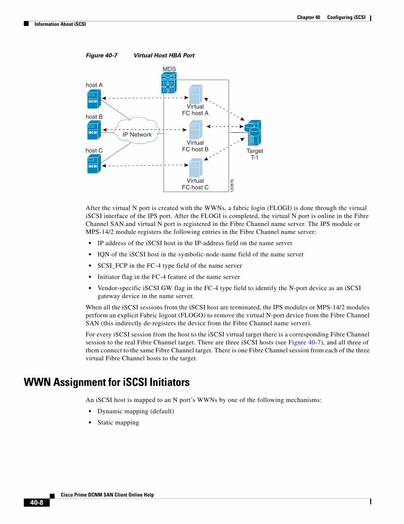
When an iSCSI host connects to the IPS module or MPS-14/2 module, a virtual host N port (HBA port) is created for the host (see Figure 40-7). Every Fibre Channel N port requires a unique Node WWN and Port WWN.
40-7Cisco Prime DCNM SAN Client Online Help
Chapter 40 Configuring iSCSIInformation About iSCSI
Figure 40-7 Virtual Host HBA Port
After the virtual N port is created with the WWNs, a fabric login (FLOGI) is done through the virtual iSCSI interface of the IPS port. After the FLOGI is completed, the virtual N port is online in the Fibre Channel SAN and virtual N port is registered in the Fibre Channel name server. The IPS module or MPS-14/2 module registers the following entries in the Fibre Channel name server:
• IP address of the iSCSI host in the IP-address field on the name server
• IQN of the iSCSI host in the symbolic-node-name field of the name server
• SCSI_FCP in the FC-4 type field of the name server
• Initiator flag in the FC-4 feature of the name server
• Vendor-specific iSCSI GW flag in the FC-4 type field to identify the N-port device as an iSCSI gateway device in the name server.
When all the iSCSI sessions from the iSCSI host are terminated, the IPS modules or MPS-14/2 modules perform an explicit Fabric logout (FLOGO) to remove the virtual N-port device from the Fibre Channel SAN (this indirectly de-registers the device from the Fibre Channel name server).
For every iSCSI session from the host to the iSCSI virtual target there is a corresponding Fibre Channel session to the real Fibre Channel target. There are three iSCSI hosts (see Figure 40-7), and all three of them connect to the same Fibre Channel target. There is one Fibre Channel session from each of the three virtual Fibre Channel hosts to the target.
WWN Assignment for iSCSI InitiatorsAn iSCSI host is mapped to an N port’s WWNs by one of the following mechanisms:
• Dynamic mapping (default)
• Static mapping
iSCSIiSCSI
host B
iSCSIiSCSI
host A
iSCSIiSCSI
host C
MDS
VirtualFC host A
VirtualFC host B
VirtualFC host C
TargetT-1
1208
76
IP Network
40-8Cisco Prime DCNM SAN Client Online Help

Chapter 40 Configuring iSCSIInformation About iSCSI
Dynamic Mapping
With dynamic mapping, an iSCSI host is mapped to a dynamically generated port WWN (pWWN) and node WWN (nWWN). Each time the iSCSI host connects it might be mapped to a different WWN. Use this option if no access control is required on the Fibre Channel target device (because the target device access control is usually configured using the host WWN).
The WWNs are allocated from the MDS switch's WWN pool. The WWN mapping to the iSCSI host is maintained as long as the iSCSI host has at least one iSCSI session to the IPS port. When all iSCSI sessions from the host are terminated and the IPS module or MPS-14/2 module performs an FLOGO for the virtual N port of the host, the WWNs are released back to the switch's Fibre Channel WWN pool. These addresses are then available for assignment to other iSCSI hosts requiring access to the Fibre Channel Fabric.
The following are three dynamic initiator modes are supported:
• iSCSI—Dynamic initiators are treated as iSCSI initiators and can access dynamic virtual targets and configured iSCSI virtual targets.
• iSLB—Dynamic initiators are treated as iSLB initiators.
• Deny—Dynamic initiators are not allowed to log in to the MDS switch.
iSCSI dynamic mapping is the default mode of operation. This configuration is distributed using CFS.
Note Configuring dynamic initiator modes is supported only through the CLI, not through Device Manager or Cisco DCNM for SAN.
Static Mapping With static mapping, an iSCSI host is mapped to a specific pWWN and nWWN. This mapping is maintained in persistent storage and each time the iSCSI host connects, the same WWN mapping is used. This mode is required if you use access control on the target device.
You can implement static mapping in one of two ways:
• User assignment—You can specify your own unique WWN by providing them during the configuration process.
• System assignment—You can request that the switch provide a WWN from the switch’s Fibre Channel WWN pool and keep the mapping in its configuration.
Tip We recommend using the system-assign option. If you manually assign a WWN, you must ensure its uniqueness (see the Fabric Configuration Guide, Cisco DCNM for SANCisco MDS 9000 Family NX-OS Fabric Configuration Guide for more information). You should not use any previously assigned WWNs.
Proxy Initiator ModeIn the event that the Fibre Channel storage device requires explicit LUN access control for every host use the transparent initiator mode (presenting one iSCSI host as one Fibre Channel host). Every iSCSI host has to be configured statically. This can mean several configuration tasks for each iSCSI host. If you do not need explicit LUN access control, using the proxy initiator mode simplifies the configuration.
40-9Cisco Prime DCNM SAN Client Online Help

Chapter 40 Configuring iSCSIInformation About iSCSI
In this mode, only one virtual host N port (HBA port) is created per IPS port. All the iSCSI hosts connecting to that IPS port will be multiplexed using the same virtual host N port (see Figure 40-8). This mode simplifies the task of statically binding WWNs. LUN mapping and assignment on the Fibre Channel storage array must be configured to allow access from the proxy virtual N port’s pWWN for all LUNs used by each iSCSI initiator that connects through this IPS port. The LUN is then assigned to each iSCSI initiator by configuring iSCSI virtual targets (see the “Static Mapping” section on page 40-6) with LUN mapping and iSCSI access control (see the “iSCSI Access Control” section on page 40-11).
Figure 40-8 Multiplexing IPS Ports
Proxy initiator mode can be configured on a per IPS port basis, in which case only iSCSI initiators terminating on that IPS port will be in this mode.
When an IPS port is configured in proxy-initiator mode, fabric login (FLOGI) is done through the virtual iSCSI interface of the IPS port. After the FLOGI is completed, the proxy-initiator virtual N port is online in the Fibre Channel fabric and virtual N port is registered in the Fibre Channel name server. The IPS module or MPS-14/2 module registers the following entries in the Fibre Channel name server:
• iSCSI interface name iSCSI slot /port is registered in the symbolic-node-name field of the name server
• SCSI_FCP in the FC-4 type field of the name server
• Initiator flag in the FC-4 feature of the name server
• Vendor specific flag (iscsi-gw) in the FC-4 type field to identify the N-port device as an iSCSI gateway device in the name server
Similar to transparent initiator mode, the user can provide a pWWN and nWWN or request a system assigned WWN for the proxy initiator N port.
Caution Enabling the proxy initiator mode of an iSCSI interface that is part of an iSLB VRRP group impacts load balancing on the interface. See the “Changing iSCSI Interface Parameters and the Impact on Load Balancing” section on page 40-21.
iSCSIiSCSI
Host B
iSCSIiSCSI
Host A
iSCSIiSCSI
Host C
MDS
Proxy initiatorhost
1208
74
IP network
40-10Cisco Prime DCNM SAN Client Online Help

Chapter 40 Configuring iSCSIInformation About iSCSI
VSAN Membership for iSCSIVSAN membership can be configured for an iSCSI interface, called the port VSAN. All the iSCSI devices that connect to this interface automatically become members of this VSAN, if it is not explicitly configured in a VSAN. The default port VSAN of an iSCSI interface is VSAN 1. Similar to Fibre Channel devices, iSCSI devices have two mechanisms by which VSAN membership can be defined.
• iSCSI host—VSAN membership to iSCSI host. (This method takes precedent over the iSCSI interface).
• iSCSI interface—VSAN membership to iSCSI interface. (All iSCSI hosts connecting to this iSCSI interface inherit the interface VSAN membership if the host is not configured in any VSAN by the iSCSI host method).
Advanced VSAN Membership for iSCSI HostsAn iSCSI host can be a member of multiple VSANs. In this case, multiple virtual Fibre Channel hosts are created, one in each VSAN in which the iSCSI host is a member. This configuration is useful when certain resources such as Fibre Channel tape devices need to be shared among different VSANs.
iSCSI Access ControlTwo methods of access control are available for iSCSI devices. Depending on the initiator mode used to present the iSCSI hosts in the Fibre Channel fabric, either or both of the access control methods can be used.
• Fiber Channel zoning-based access control—Fibre Channel zoning has been extended to support iSCSI devices, and this extension has the advantage of having a uniform, flexible access control mechanism across the whole SAN. In the case of iSCSI, multiple iSCSI devices may be connected behind an iSCSI interface. Interface-based zoning may not be useful because all iSCSI devices behind the interface will automatically be within the same zone.
• iSCSI ACL-based access control—iSCSI-based access control is applicable only if static iSCSI virtual targets are created. For a static iSCSI target, you can configure a list of iSCSI initiators that are allowed to access the targets. By default, static iSCSI virtual targets are not accessible to any iSCSI host.
Depending on the initiator mode used to present the iSCSI hosts in the Fibre Channel fabric, either or both the access control mechanisms can be used.
The following topics are included in this section:
• Fibre Channel Zoning-Based Access Control section, page 40-11
• iSCSI-Based Access Control section, page 40-12
• Enforcing Access Control section, page 40-13
Fibre Channel Zoning-Based Access Control
Cisco SAN-OS Release 3.x and NX-OS Release 4.1(1b) VSAN and zoning concepts have been extended to cover both Fibre Channel devices and iSCSI devices. Zoning is the standard access control mechanism for Fibre Channel devices, which is applied within the context of a VSAN. Fibre Channel zoning has been extended to support iSCSI devices, and this extension has the advantage of having a uniform, flexible access control mechanism across the whole SAN.
40-11Cisco Prime DCNM SAN Client Online Help

Chapter 40 Configuring iSCSIInformation About iSCSI
Common mechanisms for identifying members of a Fibre Channel zone are the following:
• Fibre Channel device pWWN.
• Interface and switch WWN. Device connecting via that interface is within the zone.
See the Fabric Configuration Guide,Cisco DCNM for SANCisco MDS 9000 Family NX-OS Fabric Configuration Guide for details on Fibre Channel zoning.
In the case of iSCSI, multiple iSCSI devices may be connected behind an iSCSI interface. Interface-based zoning may not be useful because all the iSCSI devices behind the interface will automatically be within the same zone.
In transparent initiator mode (where one Fibre Channel virtual N port is created for each iSCSI host as described in the “Transparent Initiator Mode” section on page 40-7), if an iSCSI host has static WWN mapping then the standard Fibre Channel device pWWN-based zoning membership mechanism can be used.
Zoning membership mechanism has been enhanced to add iSCSI devices to zones based on the following:
• IPv4 address/subnet mask
• IPv6 address/prefix length
• iSCSI qualified name (IQN)
• Symbolic-node-name (IQN)
For iSCSI hosts that do not have a static WWN mapping, the feature allows the IP address or iSCSI node name to be specified as zone members. Note that iSCSI hosts that have static WWN mapping can also use these features. IP address based zone membership allows multiple devices to be specified in one command by providing the subnet mask.
Note In proxy initiator mode, all iSCSI devices connecting to an IPS port gain access to the Fibre Channel fabric through a single virtual Fibre Channel N port. Zoning based on the iSCSI node name or IP address will not have any effect. If zoning based on pWWN is used, then all iSCSI devices connecting to that IPS port will be put in the same zone. To implement individual initiator access control in proxy initiator mode, configure an iSCSI ACL on the virtual target (see the “iSCSI-Based Access Control” section on page 40-12).
iSCSI-Based Access Control
iSCSI-based access control is applicable only if static iSCSI virtual targets are created (see the “Static Mapping” section on page 40-6). For a static iSCSI target, you can configure a list of iSCSI initiators that are allowed to access the targets.
By default, static iSCSI virtual targets are not accessible to any iSCSI host. You must explicitly configure accessibility to allow an iSCSI virtual target to be accessed by all hosts. The initiator access list can contain one or more initiators. The iSCSI initiator can be identified by one of the following mechanisms:
• iSCSI node name
• IPv4 address and subnet
• IPv6 address
40-12Cisco Prime DCNM SAN Client Online Help
Chapter 40 Configuring iSCSIInformation About iSCSI
Note For a transparent mode iSCSI initiator, if both Fibre Channel zoning and iSCSI ACLs are used, then for every static iSCSI target that is accessible to the iSCSI host, the initiator’s virtual N port should be in the same Fibre Channel zone as the Fibre Channel target.
Enforcing Access Control
IPS modules and MPS-14/2 modules use both iSCSI and Fibre Channel zoning-based access control lists to enforce access control. Access control is enforced both during the iSCSI discovery phase and the iSCSI session creation phase. Access control enforcement is not required during the I/O phase because the IPS module or MPS-14/2 module is responsible for the routing of iSCSI traffic to Fibre Channel.
• iSCSI discovery phase—When an iSCSI host creates an iSCSI discovery session and queries for all iSCSI targets, the IPS module or MPS-14/2 module returns only the list of iSCSI targets this iSCSI host is allowed to access based on the access control policies discussed in the previous section. The IPS module or MPS-14/2 module does this by querying the Fibre Channel name server for all the devices in the same zone as the initiator in all VSANs. It then filters out the devices that are initiators by looking at the FC4-feature field of the FCNS entry. (If a device does not register as either initiator or target in the FC4-feature field, the IPS module or MPS-14/2 module will advertise it). It then responds to the iSCSI host with the list of targets. Each will have either a static iSCSI target name that you configure or a dynamic iSCSI target name that the IPS module or MPS-14/2 module creates for it (see the “Dynamic Mapping” section on page 40-5).
• iSCSI session creation—When an IP host initiates an iSCSI session, the IPS module or MPS-14/2 module verifies if the specified iSCSI target (in the session login request) is allowed by both the access control mechanisms described in the “iSCSI-Based Access Control” section on page 40-12.
If the iSCSI target is a static mapped target, the IPS module or MPS-14/2 module verifies if the iSCSI host is allowed within the access list of the iSCSI target. If the IP host does not have access, its login is rejected. If the iSCSI host is allowed, it validates if the virtual Fibre Channel N port used by the iSCSI host and the Fibre Channel target mapped to the static iSCSI virtual target are in the same Fibre Channel zone.
If the iSCSI target is an autogenerated iSCSI target, then the IPS module or MPS-14/2 module extracts the WWN of the Fibre Channel target from the iSCSI target name and verifies if the initiator and the Fibre Channel target is in the same Fibre Channel zone or not. If they are, then access is allowed.
The IPS module or MPS-14/2 module uses the Fibre Channel virtual N port of the iSCSI host and does a zone-enforced name server query for the Fibre Channel target WWN. If the FC ID is returned by the name server, then the iSCSI session is accepted. Otherwise, the login request is rejected.
iSCSI Session AuthenticationThe IPS module or MPS-14/2 module supports the iSCSI authentication mechanism to authenticate the iSCSI hosts that request access to the storage devices. By default, the IPS modules or MPS-14/2 modules allow CHAP or None authentication of iSCSI initiators. If authentication is always used, you must configure the switch to allow only CHAP authentication.
For CHAP user name or secret validation, you can use any method supported and allowed by the Cisco MDS AAA infrastructure. AAA authentication supports a RADIUS, TACACS+, or local authentication device. See the Security Configuration Guide, Cisco DCNM for SAN.
40-13Cisco Prime DCNM SAN Client Online Help
Chapter 40 Configuring iSCSIInformation About iSCSI
The aaa authentication iscsi command enables AAA authentication for the iSCSI host and specifies the method to use. See Cisco MDS 9000 Family NX-OS Security Configuration Guide.
iSCSI Immediate Data and Unsolicited Data FeaturesCisco MDS switches support the iSCSI immediate data and unsolicited data features if requested by the initiator during the login negotiation phase. Immediate data is iSCSI write data contained in the data segment of an iSCSI command protocol data unit (PDU), such as combining the write command and write data together in one PDU. Unsolicited data is iSCSI write data that an initiator sends to the iSCSI target, such as an MDS switch, in an iSCSI data-out PDU without having to receive an explicit ready to transfer (R2T) PDU from the target.
These two features help reduce I/O time for small write commands because it removes one round-trip between the initiator and the target for the R2T PDU. As an iSCSI target, the MDS switch allows up to 64 KB of unsolicited data per command. This is controlled by the FirstBurstLength parameter during iSCSI login negotiation phase.
If an iSCSI initiator supports immediate data and unsolicited data features, these features are automatically enabled on the MDS switch with no configuration required.
Cisco MDS switches support the following advanced features for iSCSI interfaces:
• iSCSI Listener Port section, page 40-14
• TCP Tuning Parameters section, page 40-14
• Setting QoS Values section, page 40-54
• iSCSI Routing Modes section, page 40-15
iSCSI Listener Port
You can configure the TCP port number for the iSCSI interface that listens for new TCP connections. The default port number is 3260. Once you change the TCP port number, the iSCSI port only accepts TCP connections on the newly configured port.
TCP Tuning Parameters
You can configure the following TCP parameters:
• Minimum retransmit timeout (See the “Configuring Minimum Retransmit Timeout” section on page 38-26 for more information).
• Keepalive timeout.
• Maximum retransmissions (See the“Configuring Maximum Retransmissions” section on page 38-27 for more information).
• Path MTU (See the “Configuring Path MTUs” section on page 38-27 for more information).
• SACK (SACK is enabled by default for iSCSI TCP configurations).
• Window management (The iSCSI defaults are max-bandwidth is 1 Gbps, min-available-bandwidth is 70 Mbps, and round-trip-time is 1 msec). (See the “Configuring Window Management” section on page 38-28 for more information).
• Buffer size (The iSCSI default send buffer size is 4096 KB) (See the “Configuring Buffer Size” section on page 38-30 for more information).
40-14Cisco Prime DCNM SAN Client Online Help

Chapter 40 Configuring iSCSIInformation About iSCSI
• Window congestion monitoring (enabled by default and the default burst size is 50 KB) (See the “Configuring Monitoring Congestion” section on page 38-29 for more information).
• Maximum delay jitter (enabled by default and the default time is 500 microseconds).
iSCSI Routing Modes
Cisco MDS 9000 Family switches support multiple iSCSI routing modes. Each mode negotiates different operational parameters, has different advantages and disadvantages, and is suitable for different usages.
• Pass-thru mode
In pass-thru mode, the port on the IPS module or MPS 14/2 module converts and forwards read data frames from the Fibre Channel target to the iSCSI host frame-by-frame without buffering. This means that one data-in frame received is immediately sent out as one iSCSI data-in PDU.
In the opposite direction, the port on the IPS module or MPS 14/2 module limits the maximum size of iSCSI write data-out PDU that the iSCSI host can send to the maximum data size that the Fibre Channel target specifies that it can receive. The result is one iSCSI data-out PDU received sent out as one Fibre Channel data frame to the Fibre Channel target.
The absence of buffering in both directions leads to an advantage of lower forwarding latency. However, a small maximum data segment length usually results in lower data transfer performance from the host because of a higher processing overhead by the host system. Another benefit of this mode is iSCSI data digest can be enabled. This helps protect the integrity of iSCSI data carried in the PDU over what TCP checksum offers.
• Store-and-forward mode (default)
In store-and-forward mode, the port on the IPS module or MPS 14/2 module assembles all the Fibre Channel data frames of an exchange to build one large iSCSI data-in PDU before forwarding it to the iSCSI client.
In the opposite direction, the port on the IPS module or MPS 14/2 module does not impose a small data segment size on the host so the iSCSI host can send an iSCSI data-out PDU of any size (up to 256 KB). The port then waits until the whole iSCSI data-out PDU is received before it converts, or splits, the PDU, and forwards Fibre Channel frames to the Fibre Channel target.
The advantage of this mode is higher data transfer performance from the host. The disadvantages are higher transfer latency and that the iSCSI data digest (CRC) cannot be used.
Note The store-and-forward mode is the default forwarding mode.
• Cut-through mode
Cut-through mode improves the read operation performance over store-and-forward mode. The port on the IPS module or MPS 14/2 module achieves this by forwarding each Fibre Channel data-in frame to the iSCSI host as it is received without waiting for the whole exchange complete. There is no difference for write data-out operations from store-and-forward mode.
40-15Cisco Prime DCNM SAN Client Online Help
Chapter 40 Configuring iSCSIInformation About iSCSI
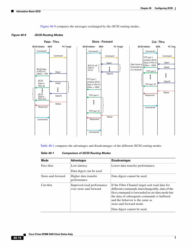
Figure 40-9 compares the messages exchanged by the iSCSI routing modes.
Figure 40-9 iSCSI Routing Modes
Table 40-1 compares the advantages and disadvantages of the different iSCSI routing modes.
Data1
Data2
iSCSI Data-in PDU #1, DSlen= 1KB
Data16
Status
iSCSIData-in PDU #16
Command1
Command
Response1
Command2
Data1
Data16
Status
TCP part 16
Command1
Command
Response1
Command2
Data1
Data16
Status
TCP part 16
Command1
Command
Response1
Command2
TCP part 2
Pass -Thru Store -Forward Cut -ThruiSCSI initiator MDS FC Target iSCSI initiator MDS FC Target iSCSI initiator MDS FC Targ
TCP part 1contains iSCSIData-in PDU #1DSlen = 16KBWait for all
Data to arrive TCP part 2
Data2Data frame isforwarded asit is received
130687
iSCSIData-inPDU #2
TCP part 1contains iSCSIData-in PDU #1DSlen = 16KB
Table 40-1 Comparison of iSCSI Routing Modes
Mode Advantages Disadvantages
Pass-thru Low-latency
Data digest can be used
Lower data transfer performance.
Store-and-forward Higher data transfer performance
Data digest cannot be used.
Cut-thru Improved read performance over store-and-forward
If the Fibre Channel target sent read data for different commands interchangeably, data of the first command is forwarded in cut-thru mode but the data of subsequent commands is buffered and the behavior is the same as store-and-forward mode.
Data digest cannot be used.
40-16Cisco Prime DCNM SAN Client Online Help

Chapter 40 Configuring iSCSIInformation About iSCSI
Caution Changing the forwarding mode of an iSCSI interface that is part of an iSLB VRRP group impacts load balancing on the interface. See the “Changing iSCSI Interface Parameters and the Impact on Load Balancing” section on page 40-21.
About iSLBThe iSCSI server load balancing (iSLB) feature provides a means to easily configure large scale iSCSI deployments containing hundreds or even thousands of initiators. iSLB provides the following features:
• The iSLB initiator configuration is simplified with support for initiator targets and auto-zones.
• Cisco Fabric Services (CFS) eliminates the need for manual configuration by distributing the iSLB initiator configuration among all MDS switches in the fabric.
• Dynamic load balancing of iSLB initiators is available using iSCSI login redirect and VRRP.
When not using iSLB, configuring iSCSI requires the following:
• You need to perform multiple configuration steps on the MDS switch, including the following:
– Initiator configuration using static pWWN and VSAN.
– Zoning configuration for initiators and targets.
– Optional create virtual target and give access to the initiator.
– Configuration of target LUN mapping and masking on the storage system for the initiator based on the static pWWN created for the initiator on the MDS switch.
• You need to duplicate the configuration manually on multiple MDS switches.
• There is no load balancing for IPS ports. For example:
– The Virtual Router Redundancy Protocol (VRRP) only supports active and backup, not load balancing.
– You must use multiple VRRP groups and configure hosts in different groups.
iSLB provides the following features:
• The iSLB initiator configuration is simplified with support for initiator targets and auto-zones.
• Cisco Fabric Services (CFS) eliminates the need for manual configuration by distributing the iSLB initiator configuration among all MDS switches in the fabric.
Note Only statically mapped iSLB initiator configuration is distributed throughout the fabric using CFS. Dynamically and statically mapped iSCSI initiator configurations are not distributed.
• Dynamic load balancing of iSLB initiators is available using iSCSI login redirect and VRRP.
About iSLB InitiatorsiSLB initiators provide the following features in addition to those supported by iSCSI initiators:
• An iSLB initiator also supports iSLB virtual targets.
• Initiator targets—These targets are configured for a particular initiator.
40-17Cisco Prime DCNM SAN Client Online Help

Chapter 40 Configuring iSCSIInformation About iSCSI
• Load balancing using iSCSI login redirect and VRRP—If iSCSI login redirect is enabled, the IPS Manager redirects incoming sessions to the best interface based on the calculated load for each interface.
• Configuration distribution to other switches using CFS.
iSLB initiators provide the following features in addition to those supported by iSCSI initiators:
• An iSLB initiator also supports iSLB virtual targets. These targets are very similar to iSCSI virtual targets with the exception that they do not include the advertise interface option and as a result are distributable using CFS.
• Initiator targets—These targets are configured for a particular initiator.
• Load balancing using iSCSI login redirect and VRRP—If load balancing is enabled, the IPS Manager redirects incoming sessions to the best interface based on the calculated load for each interface.
• Configuration distribution to other switches using CFS.
Assigning WWNs to iSLB Initiators
An iSLB host is mapped to an N port’s WWNs by one of the following mechanisms:
• Dynamic mapping (default)
• Static mapping
Note Assigning WWNs for iSLB initiators is the same as for iSCSI initiators. For information on dynamic and static mapping, see the “WWN Assignment for iSCSI Initiators” section on page 40-8.
Tip We recommend using the SystemAssign system-assign option. If you manually assign a WWN, you must ensure its uniqueness (see the Fabric Configuration Guide, Cisco DCNM for SANCisco MDS 9000 Family NX-OS Fabric Configuration Guide for more information). You should not use any previously assigned WWNs.
See the “Configuring iSLB Using Device Manager” procedure on page 40-55.
iSLB Initiator TargetsYou can configure initiator targets using the device alias or the pWWN. You can also optionally specify one or more of the following optional parameters:
• Secondary pWWN
• Secondary device alias
• LUN mapping
• IQN
• VSAN identifier
Note The VSAN identifier is optional if the target is online. If the target is not online, the VSAN identifier is required.
40-18Cisco Prime DCNM SAN Client Online Help
Chapter 40 Configuring iSCSIInformation About iSCSI
In addition, you can disable auto-zoning.
If you configure an IQN for an initiator target, then that name is used to identify the initiator target. Otherwise, a unique IQN is generated for the initiator target.
iSLB Session AuthenticationThe IPS module and MPS-14/2 module support the iSLB authentication mechanism to authenticate iSLB hosts that request access to storage. By default, the IPS module and MPS-14/2 module allow CHAP or None authentication of iSCSI initiators. If authentication is always used, you must configure the switch to allow only CHAP authentication.
For CHAP user name or secret validation you can use any method supported and allowed by the Cisco MDS AAA infrastructure (see the Security Configuration Guide, Cisco DCNM for SANCisco MDS 9000 Family NX-OS Security Configuration Guide for more information). AAA authentication supports RADIUS, TACACS+, or a local authentication device.
Note Specifying the iSLB session authentication is the same as for iSCSI. See the “iSCSI Session Authentication” section on page 40-13.
About Load Balancing Using VRRPYou can configure Virtual Router Redundancy Protocol (VRRP) load balancing for iSLB. The host is configured with a VRRP address as the portal address. When the VRRP master port receives the first iSCSI session from an initiator, it assigns a backup port to serve that particular host. The information is synchronized to all switches through CFS if recovery is needed when a master port fails. The initiator gets a temporary redirect iSCSI login response. The host then logs in to the backup port at its physical IP address. All iSCSI interfaces in a VRRP group that has load balancing enabled must have the same interface VSAN, authentication, proxy initiator mode, and forwarding mode.
You can configure Virtual Router Redundancy Protocol (VRRP) load balancing for iSLB.
Figure 40-10 shows an example of load balancing using iSLB.
40-19Cisco Prime DCNM SAN Client Online Help

Chapter 40 Configuring iSCSIInformation About iSCSI
Figure 40-10 iSLB Initiator Load Balancing Example
The host is configured with a VRRP address as the portal address. When the VRRP master port receives the first iSCSI session from an initiator, it assigns a backup port to serve that particular host. This information is synchronized to all switches through CFS if recovery is needed when a master port fails. The initiator gets a temporary redirect iSCSI login response. The host then logs in to the backup port at its physical IP address. If the backup port goes down, the host will revert to the master port. The master port knows through CFS that the backup port has gone down and redirects the host to another backup port.
Note If an Ethernet PortChannel is configured between the IPS module and an Ethernet switch, the load balancing policy on the Ethernet switch must be based on source/destination IP address only, not port numbers, for load balancing with VRRP to operate correctly.
Note An initiator can also be redirected to the physical IP address of the master interface.
Tip iSLB VRRP load balancing is based on the number of iSLB initiators and not number of sessions. Any iSLB initiator that has more targets configured than the other iSLB initiators (resulting in more sessions) should be configured with a higher load metric. For example, you can increase the load metric of the iSLB initiator with more targets to 3000 from the default value of 1000.
IPS
Fibre ChannelFibre Channel
IPS
IP network
T1 T2 T3 T4
VRRPmaster
Backup 2Backupmaster
Sessionto T1
Sessionto T1
Sessionto T2, T3
Sessionto T3, T4
1540
18
40-20Cisco Prime DCNM SAN Client Online Help

Chapter 40 Configuring iSCSIInformation About iSCSI
Caution A Gigabit Ethernet interface configured for iSLB can only be in one VRRP group because redirected sessions do not carry information about the VRRP IP address or group. This restriction allows the slave backup port to uniquely identify the VRRP group to which it belongs.
Changing iSCSI Interface Parameters and the Impact on Load BalancingAll iSCSI interfaces in a VRRP group that has load balancing enabled must have the same interface VSAN, authentication, proxy initiator mode, and forwarding mode. When you need to change any of these parameters for the iSCSI interfaces in a VRRP group, you must do so one interface at a time. During the transition time when the parameter is changed on some interfaces in the VRRP group and not the others, the master port does not redirect new initiators and instead handles them locally.
Caution Changing the VSAN, proxy initiator, authentication, and forwarding mode for iSCSI interfaces in a VRRP group can cause sessions to go down multiple times.
VRRP Load Balancing Algorithm For Selecting Gigabit Ethernet Interfaces
When the VRRP master receives an iSCSI session request from an initiator, it first checks for an existing mapping to one of the interfaces in that VRRP group. If such a mapping exists, the VRRP master redirects the initiator to that interface. If no such mapping exists, the VRRP master selects the least loaded interface and updates the selected interface’s load with the initiator’s iSLB metric (weight).
Note The VRRP master interface is treated specially and it needs to take a lower load compared to the other interfaces. This is to account for the redirection work performed by the master interface for every session. A new initiator is assigned to the master interface only if the following is true for every other interface:
VRRP backup interface load > [2 * VRRP master interface load + 1]
About iSLB Configuration Distribution Using CFSYou can distribute the configuration for iSLB initiators and initiator targets on an MDS switch. This feature lets you synchronize the iSLB configuration across the fabric from the console of a single MDS switch. The iSCSI initiator idle timeout, global authentication, and iSCSI dynamic initiator mode parameters are also distributed. CFS distribution is disabled by default.
Configuration for iSLB initiators and initiator targets on an MDS switch can be distributed using the Cisco Fabric Services (CFS). This feature allows you to synchronize the iSLB configuration across the fabric from the console of a single MDS switch. The iSCSI initiator idle timeout, iSCSI dynamic initiator mode, and global authentication parameters are also distributed. CFS distribution is disabled by default (see the System Management Configuration Guide, Cisco DCNM for SANCisco MDS 9000 Family NX-OS System Management Configuration Guide for more information).
After enabling the distribution, the first configuration starts an implicit session. All server configuration changes entered thereafter are stored in a temporary database and applied to all switches in the fabric (including the originating one) when you explicitly commit the database.
40-21Cisco Prime DCNM SAN Client Online Help
Chapter 40 Configuring iSCSIInformation About iSCSI
When CFS is enabled for iSLB, the first iSLB configuration operation starts a CFS session and locks the iSLB configuration in the fabric. The configuration changes are applied to the pending configuration database. When you make the changes to the fabric, the pending configuration is distributed to all the switches in the fabric. Each switch then validates the configuration. This check ensures the following:
• The VSANs assigned to the iSLB initiators are configured on all the switches.
• The static WWNs configured for the iSLB initiators are unique and available on all the switches.
• The iSLB initiator node names do not conflict with the iSCSI initiators on all the switches.
After the check completes successfully, all the switches commit the pending configuration to the running configuration. If any check fails, the entire commit fails.
Note iSLB is only fully supported when CFS is enabled. Using iSLB auto-zoning without enabling CFS mode may cause traffic disruption when any zone set is activated.
Note CFS does not distribute non-iSLB initiator configurations or import Fibre Channel target settings.
Non-iSLB virtual targets will continue to support advertised interfaces option.
Tip The pending changes are only available in the volatile directory and are discarded if the switch is restarted.
Locking the FabricThe first action that modifies the existing configuration creates the pending configuration and locks the feature in the fabric. Once you lock the fabric, the following conditions apply:
• No other user can make any configuration changes to this feature.
• A pending configuration is created by copying the active configuration. Modifications from this point on are made to the pending configuration and remain there until you commit the changes to the active configuration (and other switches in the fabric) or discard them.
Note iSCSI configuration changes are not allowed when an iSLB CFS session is active.
CFS Merge Process
When two fabrics merge, CFS attempts to merge the iSLB configuration from both the fabrics. A designated switch (called the dominant switch) in one fabric sends its iSLB configuration to a designated switch (called the subordinate switch) in the other fabric. The subordinate switch compares its running configuration to the received configuration for any conflicts. If no conflicts are detected, it merges the two configurations and sends it to all the switches in both the fabrics. Each switch then validates the configuration. This check ensures the following:
• VSANs assigned to the iSLB initiators are configured on all the switches.
• The static WWNs configured for the iSLB initiators are unique and available on all the switches.
• The iSLB initiator node names have no conflicts with iSCSI initiators on all the switches.
40-22Cisco Prime DCNM SAN Client Online Help
Chapter 40 Configuring iSCSIInformation About iSCSI
If this check completes successfully, the subordinate switch directs all the switches to commit the merged configuration to running configuration. If any check fails, the merge fails.
The show islb merge status command displays the exact reason for the failure. The first successful commit request after a merge failure takes the fabric out of the merge failure state.
iSLB CFS Merge Status Conflicts
Merge conflicts may occur. User intervention is required for the following merge conflicts:
• The iSCSI global authentication or iSCSI initiator idle timeout parameters are not configured the same in the two fabrics.
• The same iSLB initiator is configured differently in the two fabrics.
• An iSLB initiator in one fabric has the same name as an iSCSI initiator in the other fabric.
• Duplicate pWWN/nWWN configuration is detected in the two fabric. For example, a pWWN/nWWN configured for an iSLB initiator on one fabric is configured for an iSCSI initiator or a different iSLB initiator in the other fabric.
• A VSAN configured for an iSLB initiator in one fabric does not exist in the other fabric.
Tip Check the syslog for details on merge conflicts.
User intervention is not required when the same iSLB initiator has a different set of non-conflicting initiator targets. The merged configuration is the union of all the initiator targets.
iSCSI High AvailabilityThe following high availability features are available for iSCSI configurations:
• Transparent Target Failover section, page 40-23
• iSCSI High Availability with Host Running Multi-Path Software section, page 40-23
• iSCSI HA with Host Not Having Any Multi-Path Software section, page 40-24
• LUN Trespass for Storage Port Failover section, page 40-25
Transparent Target Failover
The following high availability features are available for iSCSI configurations:
• iSCSI high availability with host running multi-path software—In this topology, you have recovery from failure of any of the components. The host multi-path software takes care of load balancing or failover across the different paths to access the storage.
• iSCSI high availability with host not having multi-path software—Without multi-path software, the host does not have knowledge of the multiple paths to the same storage.
iSCSI High Availability with Host Running Multi-Path Software
Figure 40-11 shows the physical and logical topology for an iSCSI HA solution for hosts running multi-path software. In this scenario, the host has four iSCSI sessions. There are two iSCSI sessions from each host NIC to the two IPS ports.
40-23Cisco Prime DCNM SAN Client Online Help
Chapter 40 Configuring iSCSIInformation About iSCSI
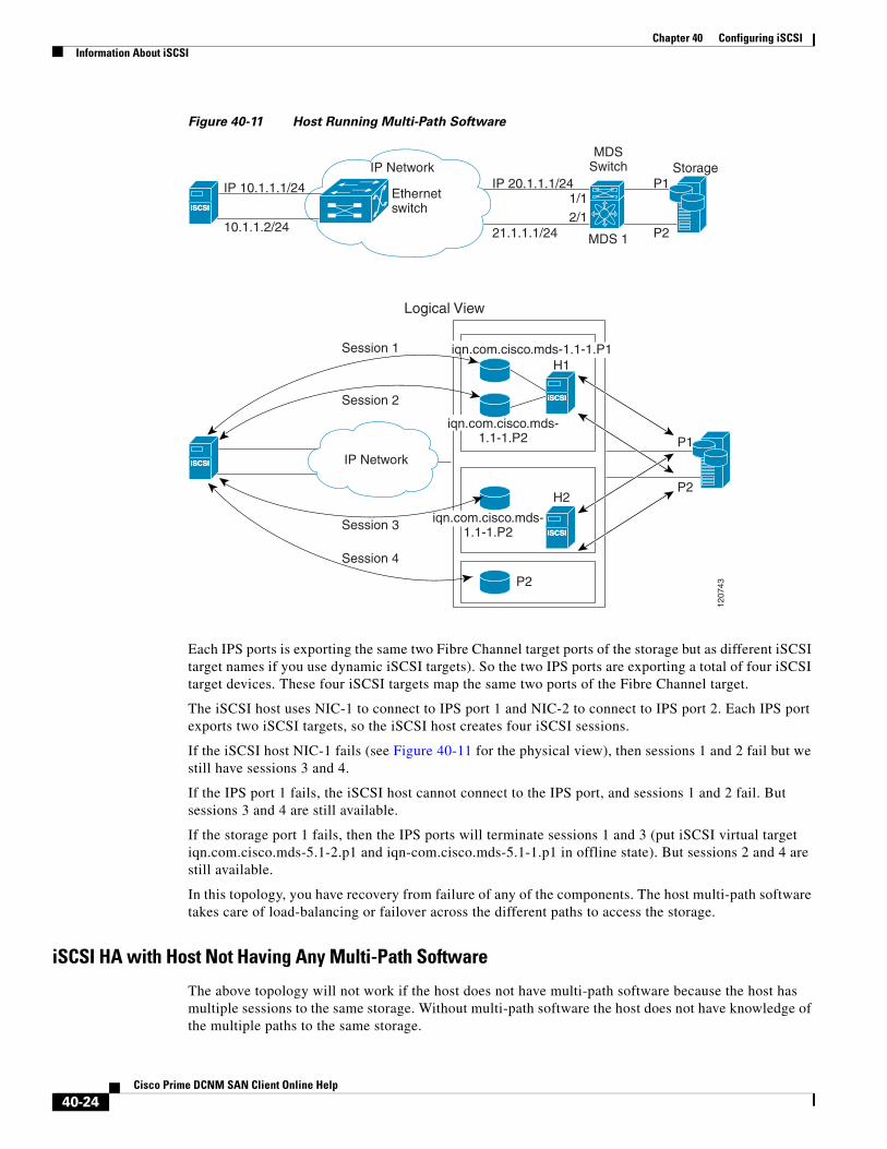
Figure 40-11 Host Running Multi-Path Software
Each IPS ports is exporting the same two Fibre Channel target ports of the storage but as different iSCSI target names if you use dynamic iSCSI targets). So the two IPS ports are exporting a total of four iSCSI target devices. These four iSCSI targets map the same two ports of the Fibre Channel target.
The iSCSI host uses NIC-1 to connect to IPS port 1 and NIC-2 to connect to IPS port 2. Each IPS port exports two iSCSI targets, so the iSCSI host creates four iSCSI sessions.
If the iSCSI host NIC-1 fails (see Figure 40-11 for the physical view), then sessions 1 and 2 fail but we still have sessions 3 and 4.
If the IPS port 1 fails, the iSCSI host cannot connect to the IPS port, and sessions 1 and 2 fail. But sessions 3 and 4 are still available.
If the storage port 1 fails, then the IPS ports will terminate sessions 1 and 3 (put iSCSI virtual target iqn.com.cisco.mds-5.1-2.p1 and iqn-com.cisco.mds-5.1-1.p1 in offline state). But sessions 2 and 4 are still available.
In this topology, you have recovery from failure of any of the components. The host multi-path software takes care of load-balancing or failover across the different paths to access the storage.
iSCSI HA with Host Not Having Any Multi-Path Software
The above topology will not work if the host does not have multi-path software because the host has multiple sessions to the same storage. Without multi-path software the host does not have knowledge of the multiple paths to the same storage.
iSCSIiSCSI
IP 10.1.1.1/24
10.1.1.2/24
iSCSIiSCSI
IP 20.1.1.1/24
21.1.1.1/24
P1
P2
Ethernetswitch
IP Network
1/12/1
MDSSwitch
MDS 1
Storage
Logical View
IP Network
Session 1
Session 2
Session 3
Session 4
iSCSIiSCSI
iSCSIiSCSI
H2
H1iqn.com.cisco.mds-1.1-1.P1
iqn.com.cisco.mds-1.1-1.P2
iqn.com.cisco.mds-1.1-1.P2
P1
P2
P2
1207
43
40-24Cisco Prime DCNM SAN Client Online Help

Chapter 40 Configuring iSCSIInformation About iSCSI
IP storage has two additional features that provide an HA solution in this scenario.
• IPS ports support the VRRP feature
• IPS has transparent Fibre Channel target failover for iSCSI static virtual targets.
Statically imported iSCSI targets have an additional option to provide a secondary pWWN for the Fibre Channel target. This can be used when the physical Fibre Channel target is configured to have an LU visible across redundant ports. When the active port fails, the secondary port becomes active and the iSCSI session switches to use the new active port (see Figure 40-12).
Figure 40-12 Static Target Importing Through Two Fibre Channel Ports
In Figure 40-12, you can create an iSCSI virtual target that is mapped to both pWWN1 and pWWN2 to provide redundant access to the Fibre Channel targets.
The failover to a secondary port is done transparently by the IPS port without impacting the iSCSI session from the host. All outstanding I/Os are terminated with a check condition status when the primary port fails. New I/Os received during the failover are not completed and receive a busy status.
Tip If you use LUN mapping, you can define a different secondary Fibre Channel LUN if the LU number is different.
Enable the optional revert-primary-port option to direct the IPS port to switch back to the primary port when the primary port is up again. If this option is disabled (default) and the primary port is up again after a switchover, the old sessions will remain with the secondary port and do not switch back to the primary port. However, any new session will use the primary port. This is the only situation when both the primary and secondary ports are used at the same time.
LUN Trespass for Storage Port Failover
In addition to the high availability of statically imported iSCSI targets, the trespass feature is available to enable the move of LUs, on an active port failure, from the active to the passive port of a statically imported iSCSI target.
In physical Fibre Channel targets, which are configured to have LUs visible over two Fibre Channel N ports, when the active port fails, the passive port takes over. Some physical Fibre Channel targets require that the trespass feature be used to move the LUs from the active port to the passive port. A statically imported iSCSI target's secondary pWWN option and an additional option of enabling the trespass feature is available for a physical Fibre Channel target with redundant ports. When the active port fails, the passive port becomes active, and if the trespass feature is enabled, the Cisco MDS switch sends a request to the target to move the LUs on the new active port. The iSCSI session switches to use the new
Switch 1iSCSI host Fibre Channel storage
pWWN 1
pWWN 2
9156
8
FC 26:00:01:02:03:04:05:06
26:00:01:02:03:10:11:12iSCSI
IPNetwork
Fibre Channel storage
Primary access = pWWN1Secondary access = pWWN 2
ABC
40-25Cisco Prime DCNM SAN Client Online Help
Chapter 40 Configuring iSCSIInformation About iSCSI
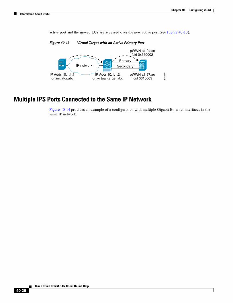
active port and the moved LUs are accessed over the new active port (see Figure 40-13).
Figure 40-13 Virtual Target with an Active Primary Port
Multiple IPS Ports Connected to the Same IP NetworkFigure 40-14 provides an example of a configuration with multiple Gigabit Ethernet interfaces in the same IP network.
iSCSIiSCSI
FCFC
IP Addr 10.1.1.1iqn.initiator.abc
IP Addr 10.1.1.2iqn.virtual-target.abc
pWWN a1:97:acfcid 0610003
pWWN a1:94:ccfcid 0x550002
IP networkPrimary
Secondary
1052
19
40-26Cisco Prime DCNM SAN Client Online Help
Chapter 40 Configuring iSCSIInformation About iSCSI
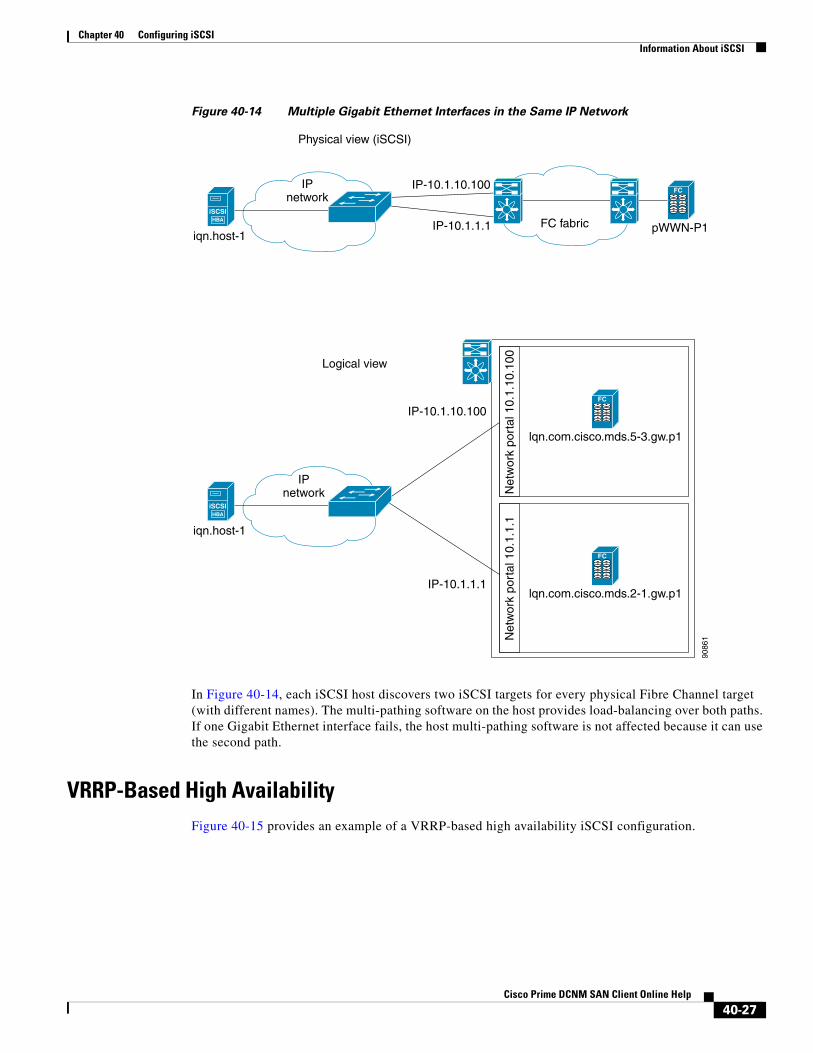
Figure 40-14 Multiple Gigabit Ethernet Interfaces in the Same IP Network
In Figure 40-14, each iSCSI host discovers two iSCSI targets for every physical Fibre Channel target (with different names). The multi-pathing software on the host provides load-balancing over both paths. If one Gigabit Ethernet interface fails, the host multi-pathing software is not affected because it can use the second path.
VRRP-Based High AvailabilityFigure 40-15 provides an example of a VRRP-based high availability iSCSI configuration.
IPnetwork
9086
1
IP-10.1.10.100
IP-10.1.1.1 FC fabric pWWN-P1iqn.host-1
iSCSIHBA
FC
lqn.com.cisco.mds.5-3.gw.p1
FC
IPnetwork
IP-10.1.10.100
Net
wor
k po
rtal
10.
1.10
.100
iqn.host-1
iSCSIHBA
lqn.com.cisco.mds.2-1.gw.p1
FC
IP-10.1.1.1
Net
wor
k po
rtal
10.
1.1.
1
Physical view (iSCSI)
Logical view
40-27Cisco Prime DCNM SAN Client Online Help

Chapter 40 Configuring iSCSIInformation About iSCSI
Figure 40-15 VRRP-Based iSCSI High Availability
In Figure 40-15, each iSCSI host discovers one iSCSI target for every physical Fibre Channel target. When the Gigabit Ethernet interface of the VRRP master fails, the iSCSI session is terminated. The host then reconnects to the target and the session comes up because the second Gigabit Ethernet interface has taken over the virtual IP address as the new master.
Ethernet PortChannel-Based High AvailabilityAll iSCSI data traffic for one iSCSI link is carried on one TCP connection. Consequently, the aggregated bandwidth is 1 Gbps for that iSCSI link.
Figure 40-16 provides a sample Ethernet PortChannel-based high availability iSCSI configuration.
IPnetwork
9086
2
VRRP across two ports
Physical view (iSCSI)
Virtual IP-10.1.1.1 FC fabric pWWN-P1iqn.host-1
iSCSIHBA
FC
lqn.com.cisco.mds.vr1.gw.p1
FC
lqn.com.cisco.mds.vr1.gw.p1
FC
Virtual IP-10.1.1.1
Net
wor
k po
rtal
10.
1.1.
1
iqn.host-1
iSCSIHBA
IPnetwork
Logical view
40-28Cisco Prime DCNM SAN Client Online Help

Chapter 40 Configuring iSCSIInformation About iSCSI
Figure 40-16 Ethernet PortChannel-Based iSCSI High Availability
In Figure 40-16, each iSCSI host discovers one iSCSI target for every physical Fibre Channel target. The iSCSI session from the iSCSI host to the iSCSI virtual target (on the IPS port) uses one of the two physical interfaces (because an iSCSI session uses one TCP connection). When the Gigabit Ethernet interface fails, the IPS module and the Ethernet switch transparently forwards all the frames on to the second Gigabit Ethernet interface.
Note If an Ethernet PortChannel is configured between the IPS module and an Ethernet switch, the load balancing policy on the Ethernet switch must be based on source/destination IP address only, not port numbers, for load balancing with VRRP to operate correctly.
iSNSInternet Storage Name Service (iSNS) allows your existing TCP/IP network to function more effectively as a SAN by automating the discovery, management, and configuration of iSCSI devices. To facilitate these functions, the iSNS server and client function as follows:
• The iSNS client registers iSCSI portals and all iSCSI devices accessible through them with an iSNS server.
• The iSNS server provides the following services for the iSNS client:
– Device registration
– State change notification
– Remote domain discovery services
All iSCSI devices (both initiator and target) acting as iSNS clients, can register with an iSNS server. iSCSI initiators can then query the iSNS server for a list of targets. The iSNS server will respond with a list of targets that the querying client can access based on configured access control parameters.
A Cisco MDS 9000 Family switch can act as an iSNS client and register all available iSCSI targets with an external iSNS server. All switches in the Cisco MDS 9000 Family with IPS modules or MPS-14/2 modules installed support iSNS server functionality. This allows external iSNS clients, such as an iSCSI initiator, to register with the switch and discover all available iSCSI targets in the SAN.
IPnetwork
9086
3
Ethernet PortChannel
IP-10.1.1.1
iqn.host-2 FC fabric
pWWN-P1
pWWN-P2
iSCSIHBA
iqn.host-1
iSCSIHBA
FC
40-29Cisco Prime DCNM SAN Client Online Help
Chapter 40 Configuring iSCSIInformation About iSCSI
About iSNS Client FunctionalityInternet Storage Name Service (iSNS) allows your existing TCP/IP network to function more effectively as a SAN by automating the discovery, management, and configuration of iSCSI devices. The iSNS client registers iSCSI portals and all iSCSI devices accessible through them with an iSNS server. All iSCSI devices (both initiator and target) acting as iSNS clients can register with an iSNS server. When the iSNS client is unable to register or deregister objects with the iSNS server (for example, the client is unable to make a TCP connection to the iSNS server), it retries every minute to reregister all iSNS objects for the affected interfaces with the iSNS server.
The iSNS client functionality on each IPS interface (Gigabit Ethernet interface or subinterface or PortChannel) registers information with an iSNS server.
Once a profile is tagged to an interface, the switch opens a TCP connection to the iSNS server IP address (using the well-known iSNS port number 3205) in the profile and registers network entity and portal objects; a unique entity is associated with each IPS interface. The switch then searches the Fibre Channel name server (FCNS) database and switch configuration to find storage nodes to register with the iSNS server.
Statically mapped virtual targets are registered if the associated Fibre Channel pWWN is present in the FCNS database and no access control configuration prevents it. A dynamically mapped target is registered if dynamic target importing is enabled. See the “Presenting Fibre Channel Targets as iSCSI Targets” section on page 40-4 for more details on how iSCSI imports Fibre Channel targets.
A storage node is deregistered from the iSNS server when it becomes unavailable when a configuration changes (such as access control change or dynamic import disabling) or the Fibre Channel storage port goes offline. It is registered again when the node comes back online.
When the iSNS client is unable to register or deregister objects with the iSNS server (for example, the client is unable to make a TCP connection to the iSNS server), it retries every minute to reregister all iSNS objects for the affected interfaces with the iSNS server. The iSNS client uses a registration interval value of 15 minutes. If the client fails to refresh the registration during this interval, the server will deregister the entries.
Untagging a profile also causes the network entity and portal to be deregistered from that interface.
Note The iSNS client is not supported on a VRRP interface.
About iSNS Server FunctionalityWhen enabled, the iSNS server on the Cisco 9000 Family MDS switch tracks all registered iSCSI devices. As a result, iSNS clients can locate other iSNS clients by querying the iSNS server. The iSNS server also provides the following functionalities:
• Allows iSNS clients to register, deregister, and query other iSNS clients registered with the iSNS server.
• Provides centralized management for enforcing access control to provide or deny access to targets from specific initiators.
• Provides a notification mechanism for registered iSNS clients to receive change notifications on the status change of other iSNS clients.
• Provides a single access control configuration for both Fibre Channel and iSCSI devices.
• Discovers iSCSI targets that do not have direct IP connectivity to the iSCSI initiators.
40-30Cisco Prime DCNM SAN Client Online Help
Chapter 40 Configuring iSCSIInformation About iSCSI
iSNS Client Registration and DeregistrationYou can use the show isns database command to display all registered iSNS clients and their associated configuration.
An iSNS client cannot query the iSNS server until it has registered. iSNS client deregistration can occur either explicitly or when the iSNS server detects that it can no longer reach the client (through ESI monitoring).
iSNS client registration and deregistration result in status change notifications (SCNs) being generated to all interested iSNS clients.
Target DiscoveryiSCSI initiators discover targets by issuing queries to the iSNS server. The server supports DevGetNext requests to search the list of targets and DevAttrQuery to determine target and portal details, such as the IP address or port number to which to connect.
On receiving a query request from the iSCSI client, the iSNS server queries the Fibre Channel Name Server (FCNS) to obtain a list of Fibre Channel targets that are accessible by the querying initiator. The result of this query depends on zoning configuration currently active and current configuration(s) of the initiator. The iSNS server will subsequently use the iSCSI target configuration(s) (virtual target and dynamic import configuration) to translate the Fibre Channel target to an equivalent iSCSI target. At this stage it also applies any access control configured for the virtual target. A response message with the target details is then sent back to the query initiator.
The iSNS server sends a consolidated response containing all possible targets and portals to the querying initiator. For example, if a Fibre Channel target is exported as different iSCSI targets on different IPS interfaces, the iSNS server will respond with a list of all possible iSCSI targets and portals.
In order to keep the list of targets updated, the iSNS server sends state change notifications (SCN) to the client whenever an iSCSI target becomes reachable or unreachable. The client is then expected to rediscover its list of accessible targets by initiating another iSNS query. Reachability of iSCSI targets changes when any one of the following occurs:
• Target goes up or down.
• Dynamic import of FC target configuration changes.
• Zone set changes.
• Default zone access control changes.
• IPS interface state changes.
• Initiator configuration change makes the target accessible or inaccessible.
About Cloud DiscoveryWhen an iSNS server receives a query request, it responds with a list of available targets and the portals through which the initiator can reach the target. The IP network configuration outside the MDS switch may result in only a subset of Gigabit Ethernet interfaces being reachable from the initiator. To ensure that the set of portals returned to the initiator is reachable, the iSNS server needs to know the set of Gigabit Ethernet interfaces that are reachable from a given initiator.
40-31Cisco Prime DCNM SAN Client Online Help

Chapter 40 Configuring iSCSILicensing Requirements for iSCSI
Note iSNS Cloud Discovery is not supported on the Cisco Fabric Switch for IBM BladeCenter and Cisco Fabric Switch for HP c-Class BladeSystem.
The iSNS cloud discovery feature provides information to the iSNS server on the various interfaces reachable from an initiator by partitioning the interfaces on a switch into disjointed IP clouds. This discovery is achieved by sending messages to all other known IPS ports that are currently up and, depending on the response (or the lack of it), determines if the remote IPS port is in the same IP network or in a different IP network.
Cloud discovery is initiated when the following events occur:
• Manual requests from the CLI initiate cloud discovery from the CLI. This action causes the destruction of existing memberships and makes new ones.
• Auto-discovery of the interface results in an interface being assigned to its correct cloud. All other cloud members are not affected. The membership of each cloud is built incrementally and is initiated by the following events:
– A Gigabit Ethernet interface comes up. This can be a local or remote Gigabit Ethernet interface.
– The IP address of a Gigabit Ethernet interface changes.
– The VRRP configuration on a port changes.
The iSNS server distributes cloud and membership information across all the switches using CFS. Therefore, the cloud membership view is the same on all the switches in the fabric.
Note For CFS distribution to operate correctly for iSNS cloud discovery, all switches in the fabric must be running Cisco SAN-OS Release 3.0(1) or NX-OS 4.1(1b) and later.
Licensing Requirements for iSCSIThe following table shows the licensing requirements for this feature:
Guidelines and LimitationsiSLB configuration has the following limits:
• The maximum number of iSLB and iSCSI initiators supported in a fabric is 2000.
• The maximum number of iSLB and iSCSI sessions supported by an IPS port in either transparent or proxy initiator mode is 500.
• The maximum number of iSLB initiators supported in a fabric is 2000.
• The maximum number of iSLB initiators and iSCSI sessions supported by a switch is 5000.
License License Description
Enterprise package (ENTERPRISE_PKG) It comprises the IP security (IPsec) protocol for iSCSI and FCIP using the MPS-14/2 module or Cisco MDS 9216i Switch.
40-32Cisco Prime DCNM SAN Client Online Help

Chapter 40 Configuring iSCSIDefault Settings
• The maximum number of iSLB sessions per IPS port in either transparent or proxy initiator mode is 500.
• The maximum number of iSLB and iSCSI targets supported in a fabric is 6000.
• The maximum number of switches in a fabric that can have iSLB with CFS distribution enabled is four.
• No more than 200 new iSLB initiators can be added to the pending configuration. Before adding more initiators, you must commit the configuration.
• You cannot disable iSCSI if you have more than 200 iSLB initiators in the running configuration. Reduce the number of iSLB initiators to fewer than 200 before disabling iSCSI.
• iSLB can be used without CFS distribution but if iSLB auto-zone feature is used, traffic is disrupted when any zoneset is activated.
• If IVR and iSLB features are enabled in the same fabric, you should have at least one switch in the fabric where both these features are enabled. Any zoning-related configuration and activation (for normal zones, IVR zones, or iSLB zones) must be performed on this switch. Otherwise, there may be traffic disruption in the fabric.
Default SettingsTable 40-2 lists the default settings for iSCSI parameters.
Table 40-2 Default iSCSI Parameters
Parameters Default
Number of TCP connections One per iSCSI session
minimum-retransmit-time 300 msec
keepalive-timeout 60 seconds
max-retransmissions 4 retransmissions
PMTU discovery Enabled
pmtu-enable reset-timeout 3600 sec
SACK Enabled
max-bandwidth 1 Gbps
min-available-bandwidth 70 Mbps
round-trip-time 1 msec
Buffer size 4096 KB
Control TCP and data connection No packets are transmitted
TCP congestion window monitoring Enabled
Burst size 50 KB
Jitter 500 microseconds
TCP connection mode Active mode is enabled
Fibre Channel targets to iSCSI Not imported
40-33Cisco Prime DCNM SAN Client Online Help
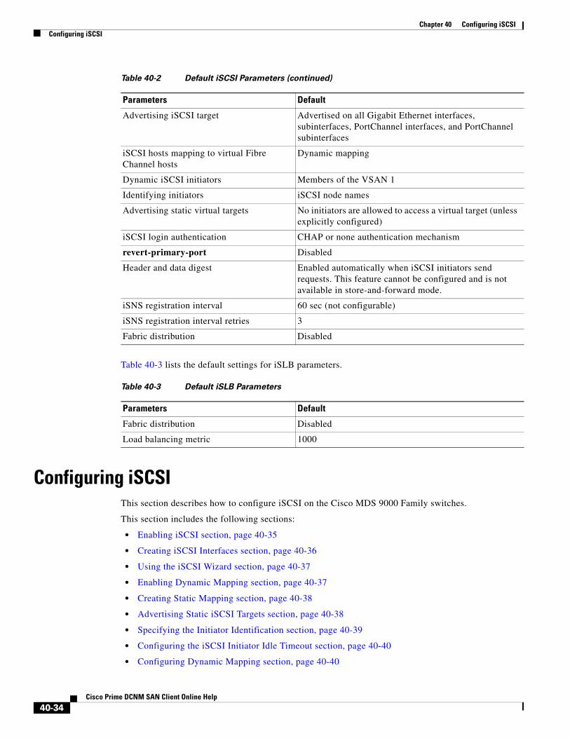
Chapter 40 Configuring iSCSIConfiguring iSCSI
Table 40-3 lists the default settings for iSLB parameters.
Configuring iSCSIThis section describes how to configure iSCSI on the Cisco MDS 9000 Family switches.
This section includes the following sections:
• Enabling iSCSI section, page 40-35
• Creating iSCSI Interfaces section, page 40-36
• Using the iSCSI Wizard section, page 40-37
• Enabling Dynamic Mapping section, page 40-37
• Creating Static Mapping section, page 40-38
• Advertising Static iSCSI Targets section, page 40-38
• Specifying the Initiator Identification section, page 40-39
• Configuring the iSCSI Initiator Idle Timeout section, page 40-40
• Configuring Dynamic Mapping section, page 40-40
Advertising iSCSI target Advertised on all Gigabit Ethernet interfaces, subinterfaces, PortChannel interfaces, and PortChannel subinterfaces
iSCSI hosts mapping to virtual Fibre Channel hosts
Dynamic mapping
Dynamic iSCSI initiators Members of the VSAN 1
Identifying initiators iSCSI node names
Advertising static virtual targets No initiators are allowed to access a virtual target (unless explicitly configured)
iSCSI login authentication CHAP or none authentication mechanism
revert-primary-port Disabled
Header and data digest Enabled automatically when iSCSI initiators send requests. This feature cannot be configured and is not available in store-and-forward mode.
iSNS registration interval 60 sec (not configurable)
iSNS registration interval retries 3
Fabric distribution Disabled
Table 40-2 Default iSCSI Parameters (continued)
Parameters Default
Table 40-3 Default iSLB Parameters
Parameters Default
Fabric distribution Disabled
Load balancing metric 1000
40-34Cisco Prime DCNM SAN Client Online Help

Chapter 40 Configuring iSCSIConfiguring iSCSI
• Configuring Static Mapping section, page 40-41
• Making the Dynamic iSCSI Initiator WWN Mapping Static section, page 40-42
• Checking for WWN Conflicts section, page 40-43
• Configuring the Proxy Initiator section, page 40-44
• Configuring VSAN Membership for iSCSI Hosts section, page 40-45
• Configuring Default Port VSAN for iSCSI Interfaces section, page 40-46
• Adding iSCSI Initiator to the Zone Database section, page 40-47
• Configuring Access Control in iSCSI section, page 40-47
• Configuring AAA Authentication for an iSCSI User section, page 40-49
• Configuring Authentication Mechanism section, page 40-49
• Changing the iSCSI Routing Mode section, page 40-54
• Configuring iSLB Using Device Manager section, page 40-55
• Configuring iSLB Initiator Names or IP Addresses section, page 40-56
• Assigning VSAN Membership for iSLB Initiators section, page 40-58
• Configuring and Activating Zones for iSLB Initiators and Initiator Targets section, page 40-62
• Restricting iSLB Initiator Authentication section, page 40-63
Enabling iSCSITo use the iSCSI feature, you must explicitly enable iSCSI on the required switches in the fabric. Alternatively, you can enable or disable the iSCSI feature directly on the required modules using Cisco DCNM for SAN or Device Manager. By default, this feature is disabled in all switches in the Cisco MDS 9000 Family.
Caution When you disable this feature, all related configurations are automatically discarded.
To enable iSCSI on any participating switch, follow these steps:
To enable iSCSI on any switch, follow these steps:
Command Purpose
Step 1 switch# config t Enters the configuration commands, one per line. End with CNTL/Z.
Step 2 switch(config)# feature iscsi Enables iSCSI on that switch.
switch(config)# iscsi enable module <x> Enables iSCSI modules on the switch.
Note New command added so that SME and iSCSI are available on the same switch.
switch(config)# no iscsi enable module <x>
Disables the iSCSI module on the switch.
switch(config)# no feature iscsi Disables (default) iSCSI on that switch.
40-35Cisco Prime DCNM SAN Client Online Help
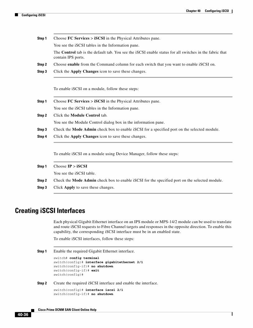
Chapter 40 Configuring iSCSIConfiguring iSCSI
Step 1 Choose FC Services > iSCSI in the Physical Attributes pane.
You see the iSCSI tables in the Information pane.
The Control tab is the default tab. You see the iSCSI enable status for all switches in the fabric that contain IPS ports.
Step 2 Choose enable from the Command column for each switch that you want to enable iSCSI on.
Step 3 Click the Apply Changes icon to save these changes.
To enable iSCSI on a module, follow these steps:
Step 1 Choose FC Services > iSCSI in the Physical Attributes pane.
You see the iSCSI tables in the Information pane.
Step 2 Click the Module Control tab.
You see the Module Control dialog box in the information pane.
Step 3 Check the Mode Admin check box to enable iSCSI for a specified port on the selected module.
Step 4 Click the Apply Changes icon to save these changes.
To enable iSCSI on a module using Device Manager, follow these steps:
Step 1 Choose IP > iSCSI
You see the iSCSI table.
Step 2 Check the Mode Admin check box to enable iSCSI for the specified port on the selected module.
Step 3 Click Apply to save these changes.
Creating iSCSI InterfacesEach physical Gigabit Ethernet interface on an IPS module or MPS-14/2 module can be used to translate and route iSCSI requests to Fibre Channel targets and responses in the opposite direction. To enable this capability, the corresponding iSCSI interface must be in an enabled state.
To enable iSCSI interfaces, follow these steps:
Step 1 Enable the required Gigabit Ethernet interface.
switch# config terminalswitch(config)# interface gigabitethernet 2/1switch(config-if)# no shutdownswitch(config-if)# exitswitch(config)#
Step 2 Create the required iSCSI interface and enable the interface.
switch(config)# interface iscsi 2/1switch(config-if)# no shutdown
40-36Cisco Prime DCNM SAN Client Online Help

Chapter 40 Configuring iSCSIConfiguring iSCSI
Using the iSCSI WizardTo use the iSCSI wizard in Cisco DCNM-SAN, follow these steps:
Step 1 Click the iSCSI Setup Wizard icon.
You see the iSCSI Wizard Configure Initiator dialog box.
Step 2 Select an existing iSCSI initiator or add the iSCSI node name or IP address for a new iSCSI initiator.
Step 3 Select the switch for this iSCSI initiator if you are adding a new iSCSI initiator and click Next.
You see the iSCSI Wizard Select Targets dialog box.
Step 4 Select the VSAN and targets to associate with this iSCSI initiator and click Next.
Note The iSCSI wizard turns on the Dynamic Import FC Targets feature.
You see the iSCSI Wizard Select Zone dialog box.
Step 5 Set the zone name for this new iSCSI zone and check the ReadOnly check box if needed.
Step 6 Click Finish to create this iSCSI initiator.
If created, the target VSAN is added to the iSCSI host VSAN list.
Note iSCSI wizard automatically turns on the Dynamic FC target import.
Enabling Dynamic MappingTo enable dynamic mapping of Fibre Channel targets into iSCSI, follow these steps:
To enable dynamic mapping of Fibre Channel targets into iSCSI using Device Manager, follow these steps:
Step 1 Choose IP > iSCSI.
• You see the iSCSI configuration.
Step 2 Click the Target tab to display a list of existing iSCSI targets.
Command Purpose
Step 1 switch# config terminalswitch(config)#
Enters configuration mode.
Step 2 switch(config)# iscsi import target fc IPS modules and MPS-14/2 modules dynamically import all Fibre Channel targets in the Fibre Channel SAN into the IP network.
40-37Cisco Prime DCNM SAN Client Online Help

Chapter 40 Configuring iSCSIConfiguring iSCSI
Step 3 Check the Dynamically Import FC Targets check box.
Step 4 Click Apply to save this change.
Creating Static MappingTo create a static iSCSI virtual target for the entire Fibre Channel target port using Device Manager, follow these steps:
Step 1 Click IP > iSCSI.
You see the iSCSI configuration.
Step 2 Click the Targets tab to display a list of existing iSCSI targets .
Step 3 Click Create to create an iSCSI target.
You see the Create iSCSI Targets dialog box.
Step 4 Set the iSCSI target node name in the iSCSI Name field, in IQN format.
Step 5 Set the Port WWN field for the Fibre Channel target port you are mapping.
Step 6 Click the Select from List radio button and set the iSCSI initiator node names or IP addresses that you want this virtual iSCSI target to access, or click the All radio button to let the iSCSI target access all iSCSI initiators. Also see the “iSCSI Access Control” section on page 40-11.
Step 7 Click the Select from List radio button and check each interface you want to advertise the iSCSI targets on or click the All radio button to advertise all interfaces.
Step 8 Click Apply to save this change.
Tip An iSCSI target cannot contain more than one Fibre Channel target port. If you have already mapped the whole Fibre Channel target port, you cannot use the LUN mapping option.
Note See the “iSCSI-Based Access Control” section on page 40-12 for more information on controlling access to statically mapped targets.
Advertising Static iSCSI TargetsYou can limit the Gigabit Ethernet interfaces through which static iSCSI targets are advertised. By default iSCSI targets are advertised on all Gigabit Ethernet interfaces, subinterfaces, PortChannel interfaces, and PortChannel subinterfaces.
To configure a specific interface that should advertise the iSCSI virtual target using Device Manager, follow these steps:
40-38Cisco Prime DCNM SAN Client Online Help

Chapter 40 Configuring iSCSIConfiguring iSCSI
Step 1 Select IP > iSCSI.
You see the iSCSI configuration.
Step 2 Click the Targets tab to display a list of existing iSCSI targets.
Step 3 Right-click the iSCSI target that you want to modify and click Edit Advertised.
You see the Advertised Interfaces dialog box.
Step 4 (Optional) Right-click an interface that you want to delete and click Delete.
Step 5 (Optional) Click Create to advertise on more interfaces.
You see the Create Advertised Interfaces dialog box.
To configure a specific interface that should advertise the iSCSI virtual target, follow these steps:
Specifying the Initiator IdentificationYou can configure the iSCSI initiator identification mode on each IPS port and all the iSCSI hosts terminating on the IPS port will be identified according to that configuration. The default mode is to identify the initiator by name.
To specify the initiator identification mode, follow these steps:
To specify the initiator identification mode, follow these steps:
Step 1 Choose Interfaces > FC Logical from the Physical Attributes pane.
You see the interfaces configuration in the Information pane.
Command Purpose
Step 1 switch(config-iscsi-tgt)# advertise interface GigabitEthernet 2/5
Advertises the virtual target only on the specified interface. By default, it is advertised on all interfaces in all IPS modules or MPS-14/2 modules.
Note To advertise the virtual target on multiple interfaces, issue the command for each interface.
switch(config-iscsi-tgt)# no advertise interface GigabitEthernet 2/5
Removes this interface from the list of interfaces from which this target is advertised.
Command Purpose
Step 1 switch# config tswitch(config)#
Enters the configuration mode.
Step 2 switch(config)# interface iscsi 4/1switch(config-if)#
Selects the iSCSI interface on the switch that identifies all the initiators.
Step 3 switch(config-if)# switchport initiator id ip-address
Identifies the iSCSI initiator based on the IP address.
switch(config-if)# switchport initiator id name
Identifies the iSCSI initiator based on the initiator node name. This is the default behavior.
40-39Cisco Prime DCNM SAN Client Online Help

Chapter 40 Configuring iSCSIConfiguring iSCSI
Step 2 Click the iSCSI tab.
You see the iSCSI interfaces configuration.
Step 3 Right-click the Initiator ID Mode field for the iSCSI interface that you want to modify and select name or ipaddress from the drop-down menu.
Step 4 Click Apply Changes to save this change.
Configuring the iSCSI Initiator Idle TimeoutiSCSI initiator idle timeout specifies the time for which the virtual Fibre Channel N port is kept idle after the initiator logs out from its last iSCSI session. The default value for this timer is 300 seconds. This is useful to avoid N ports logging in to and logging off of the Fibre Channel SAN as transient failure occurs in the IP network. This helps reduce unnecessary RSCNs being generated in the Fibre Channel SAN.
To configure the initiator idle timeout, follow these steps:
To configure the initiator idle timeout, follow these steps:
Step 1 Choose End Devices > iSCSI in the Physical Attributes pane.
You see the iSCSI tables in the Information pane.
Step 2 Click the Globals tab.
You see the iSCSI global configuration.
Step 3 Right-click on the InitiatorIdle Timeout field that you want to modify and enter the new timeout value.
Step 4 Click the Apply Changes icon to save these changes.
Configuring Dynamic MappingTo configure dynamic mapping (using the name option) for an iSCSI initiator, follow these steps:
Command Purpose
Step 1 switch# config tswitch(config)#
Enters the configuration mode.
Step 2 switch(config)# iscsi initiator idle-timeout 10
Configures the iSCSI initiators to have an idle timeout value of 10 seconds.
Command Purpose
Step 1 switch# config tswitch(config)#
Enters configuration mode.
40-40Cisco Prime DCNM SAN Client Online Help
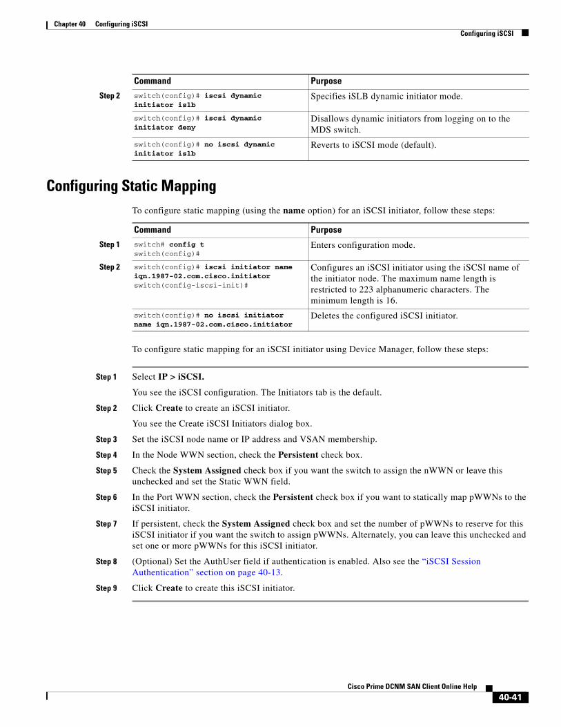
Chapter 40 Configuring iSCSIConfiguring iSCSI
Configuring Static MappingTo configure static mapping (using the name option) for an iSCSI initiator, follow these steps:
To configure static mapping for an iSCSI initiator using Device Manager, follow these steps:
Step 1 Select IP > iSCSI.
You see the iSCSI configuration. The Initiators tab is the default.
Step 2 Click Create to create an iSCSI initiator.
You see the Create iSCSI Initiators dialog box.
Step 3 Set the iSCSI node name or IP address and VSAN membership.
Step 4 In the Node WWN section, check the Persistent check box.
Step 5 Check the System Assigned check box if you want the switch to assign the nWWN or leave this unchecked and set the Static WWN field.
Step 6 In the Port WWN section, check the Persistent check box if you want to statically map pWWNs to the iSCSI initiator.
Step 7 If persistent, check the System Assigned check box and set the number of pWWNs to reserve for this iSCSI initiator if you want the switch to assign pWWNs. Alternately, you can leave this unchecked and set one or more pWWNs for this iSCSI initiator.
Step 8 (Optional) Set the AuthUser field if authentication is enabled. Also see the “iSCSI Session Authentication” section on page 40-13.
Step 9 Click Create to create this iSCSI initiator.
Step 2 switch(config)# iscsi dynamic initiator islb
Specifies iSLB dynamic initiator mode.
switch(config)# iscsi dynamic initiator deny
Disallows dynamic initiators from logging on to the MDS switch.
switch(config)# no iscsi dynamic initiator islb
Reverts to iSCSI mode (default).
Command Purpose
Command Purpose
Step 1 switch# config tswitch(config)#
Enters configuration mode.
Step 2 switch(config)# iscsi initiator name iqn.1987-02.com.cisco.initiatorswitch(config-iscsi-init)#
Configures an iSCSI initiator using the iSCSI name of the initiator node. The maximum name length is restricted to 223 alphanumeric characters. The minimum length is 16.
switch(config)# no iscsi initiator name iqn.1987-02.com.cisco.initiator
Deletes the configured iSCSI initiator.
40-41Cisco Prime DCNM SAN Client Online Help

Chapter 40 Configuring iSCSIConfiguring iSCSI
To configure static mapping (using the ip-address option) for an iSCSI initiator, follow these steps:
To assign the WWN for an iSCSI initiator, follow these steps:
Note If the system-assign option is used to configure WWNs for an iSCSI initiator, when the configuration is saved to an ASCII file the system-assigned WWNs are also saved. Subsequently if you perform a write erase, you must manually delete the WWN configuration from the ASCII file. Failing to do so can cause duplicate WWN assignments if the ASCII configuration file is reapplied on the switch.
Making the Dynamic iSCSI Initiator WWN Mapping StaticAfter a dynamic iSCSI initiator has already logged in, you may decide to permanently keep the automatically assigned nWWN/pWWN mapping so this initiator uses the same mapping the next time it logs in.
You can convert a dynamic iSCSI initiator to static iSCSI initiator and make its WWNs persistent (see the “Dynamic Mapping” section on page 40-9).
Note You cannot convert a dynamic iSCSI initiator to a static iSLB initiator or a dynamic iSLB initiator to a static iSCSI initiator.
Command Purpose
Step 1 switch# config terminalswitch(config)#
Enters configuration mode.
Step 2 switch(config)# iscsi initiator ip-address 10.50.0.0switch(config-iscsi-init)#
Configures an iSCSI initiator using the IPv4 address of the initiator node.
switch(config)# iscsi initiator ip-address 2001:0DB8:800:200C::417Aswitch(config-iscsi-init)#
Configures an iSCSI initiator using the IPv6 unicast address of the initiator node.
switch(config)# no iscsi initiator ip-address 2001:0DB8:800:200C::417A
Deletes the configured iSCSI initiator.
Command Purpose
Step 1 switch(config-iscsi-init)# static nWWN system-assign
Uses the switch’s WWN pool to allocate the nWWN for this iSCSI initiator and keeps it persistent.
switch(config-iscsi-init)# static nWWN 20:00:00:05:30:00:59:11
Assigns the user provided WWN as the nWWN for the iSCSI initiator. You can only specify one nWWN for each iSCSI node.
Step 2 switch(config-iscsi-init)# static pWWN system-assign 2
Uses the switch’s WWN pool to allocate two pWWNs for this iSCSI initiator and keeps them persistent. The range is from 1 to 64.
switch(config-iscsi-init)# static pWWN 21:00:00:20:37:73:3b:20
Assigns the user provided WWN as the pWWN for the iSCSI initiator.
40-42Cisco Prime DCNM SAN Client Online Help
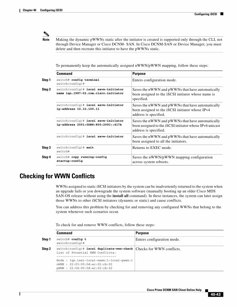
Chapter 40 Configuring iSCSIConfiguring iSCSI
Note Making the dynamic pWWNs static after the initiator is created is supported only through the CLI, not through Device Manager or Cisco DCNM- SAN. In Cisco DCNM-SAN or Device Manager, you must delete and then recreate this initiator to have the pWWNs static.
To permanently keep the automatically assigned nWWN/pWWN mapping, follow these steps:
Checking for WWN ConflictsWWNs assigned to static iSCSI initiators by the system can be inadvertently returned to the system when an upgrade fails or you downgrade the system software (manually booting up an older Cisco MDS SAN-OS release without using the install all command). In these instances, the system can later assign those WWNs to other iSCSI initiators (dynamic or static) and cause conflicts.
You can address this problem by checking for and removing any configured WWNs that belong to the system whenever such scenarios occur.
To check for and remove WWN conflicts, follow these steps:
Command Purpose
Step 1 switch# config terminalswitch(config)#
Enters configuration mode.
Step 2 switch(config)# iscsi save-initiator name iqn.1987-02.com.cisco.initiator
Saves the nWWN and pWWNs that have automatically been assigned to the iSCSI initiator whose name is specified.
switch(config)# iscsi save-initiator ip-address 10.10.100.11
Saves the nWWN and pWWNs that have automatically been assigned to the iSCSI initiator whose IPv4 address is specified.
switch(config)# iscsi save-initiator ip-address 2001:0DB8:800:200C::417A
Saves the nWWN and pWWNs that have automatically been assigned to the iSCSI initiator whose IPv6 unicast address is specified.
switch(config)# iscsi save-initiator Saves the nWWN and pWWNs that have automatically been assigned to all the initiators.
Step 3 switch(config)# exitswitch#
Returns to EXEC mode.
Step 4 switch# copy running-config startup-config
Saves the nWWN/pWWN mapping configuration across system reboots.
Command Purpose
Step 1 switch# config tswitch(config)#
Enters configuration mode.
Step 2 switch(config)# iscsi duplicate-wwn-checkList of Potential WWN Conflicts:-------------------------------- Node : iqn.test-local-nwwn:1-local-pwwn:1nWWN : 22:03:00:0d:ec:02:cb:02pWWN : 22:04:00:0d:ec:02:cb:02
Checks for WWN conflicts.
40-43Cisco Prime DCNM SAN Client Online Help

Chapter 40 Configuring iSCSIConfiguring iSCSI
To permanently keep the automatically assigned nWWN mapping, follow these steps:
Step 1 Choose End Devices > iSCSI in the Physical Attributes pane.
You see the iSCSI tables in the Information pane.
Step 2 Click the Initiators tab.
You see the iSCSI initiators configured.
Step 3 Check the Persistent Node WWN check box for the iSCSI initiators that you want to make static.
Step 4 Click the Apply Changes icon to save these changes.
Configuring the Proxy InitiatorTo configure the proxy initiator, follow these steps:
To configure the proxy initiator, follow these steps:
Step 1 Expand Switches, expand FC Interfaces, and then select Logical in the Physical Attributes pane.
You see the Interface tables in the Information pane.
Step 2 In Device Manager, select Interface > Ethernet and iSCSI.
You see the Ethernet Interfaces and iSCSI dialog box.
Step 3 switch(config)# iscsi initiator name iqn.test-local-nwwn:1-local-pwwn:1
Enters iSCSI initiator configuration mode for the initiator named iqn.test-local-nwwn:1-local-pwwn:1.
Step 4 switch(config-iscsi-init)# no static nWWN 22:03:00:0d:ec:02:cb:02
Removes a conflicting nWWN.
Step 5 switch(config-iscsi-init)# no static pWWN 22:04:00:0d:ec:02:cb:02
Removes a conflicting pWWN.
Command Purpose
Command Purpose
Step 1 switch# config terminalswitch(config)#
Enters configuration mode.
Step 2 switch(config)# interface iscsi 4/1switch(config-if)#
Selects the iSCSI interface on the switch that initiators will connect to.
Step 3 switch(config-if)# switchport proxy-initiator
Configures the proxy initiator mode with system-assignment nWWN and pWWN.
switch(config-if)# no switchport proxy-initiator
Disables the proxy initiator mode.
Step 4 switch(config-if)# switchport proxy-initiator nWWN 11:11:11:11:11:11:11:11 pwwn 22:22:22:22:22:22:22:22
(Optional) Configures the proxy initiator mode using the specified WWNs.
switch(config-if)# no switchport proxy-initiator nWWN 11:11:11:11:11:11:11:11 pwwn 22:22:22:22:22:22:22:22
Disables the proxy initiator mode.
40-44Cisco Prime DCNM SAN Client Online Help
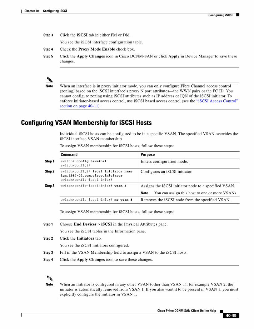
Chapter 40 Configuring iSCSIConfiguring iSCSI
Step 3 Click the iSCSI tab in either FM or DM.
You see the iSCSI interface configuration table.
Step 4 Check the Proxy Mode Enable check box.
Step 5 Click the Apply Changes icon in Cisco DCNM-SAN or click Apply in Device Manager to save these changes.
Note When an interface is in proxy initiator mode, you can only configure Fibre Channel access control (zoning) based on the iSCSI interface’s proxy N port attributes—the WWN pairs or the FC ID. You cannot configure zoning using iSCSI attributes such as IP address or IQN of the iSCSI initiator. To enforce initiator-based access control, use iSCSI based access control (see the “iSCSI Access Control” section on page 40-11).
Configuring VSAN Membership for iSCSI HostsIndividual iSCSI hosts can be configured to be in a specific VSAN. The specified VSAN overrides the iSCSI interface VSAN membership.
To assign VSAN membership for iSCSI hosts, follow these steps:
To assign VSAN membership for iSCSI hosts, follow these steps:
Step 1 Choose End Devices > iSCSI in the Physical Attributes pane.
You see the iSCSI tables in the Information pane.
Step 2 Click the Initiators tab.
You see the iSCSI initiators configured.
Step 3 Fill in the VSAN Membership field to assign a VSAN to the iSCSI hosts.
Step 4 Click the Apply Changes icon to save these changes.
Note When an initiator is configured in any other VSAN (other than VSAN 1), for example VSAN 2, the initiator is automatically removed from VSAN 1. If you also want it to be present in VSAN 1, you must explicitly configure the initiator in VSAN 1.
Command Purpose
Step 1 switch# config terminalswitch(config)#
Enters configuration mode.
Step 2 switch(config)# iscsi initiator name iqn.1987-02.com.cisco.initiatorswitch(config-iscsi-init)#
Configures an iSCSI initiator.
Step 3 switch(config-iscsi-init)# vsan 3 Assigns the iSCSI initiator node to a specified VSAN.
Note You can assign this host to one or more VSANs.
switch(config-iscsi-init)# no vsan 5 Removes the iSCSI node from the specified VSAN.
40-45Cisco Prime DCNM SAN Client Online Help
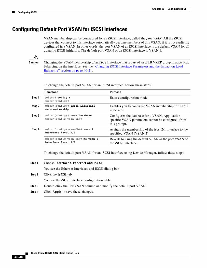
Chapter 40 Configuring iSCSIConfiguring iSCSI
Configuring Default Port VSAN for iSCSI InterfacesVSAN membership can be configured for an iSCSI interface, called the port VSAN. All the iSCSI devices that connect to this interface automatically become members of this VSAN, if it is not explicitly configured in a VSAN. In other words, the port VSAN of an iSCSI interface is the default VSAN for all dynamic iSCSI initiators. The default port VSAN of an iSCSI interface is VSAN 1.
Caution Changing the VSAN membership of an iSCSI interface that is part of an iSLB VRRP group impacts load balancing on the interface. See the “Changing iSCSI Interface Parameters and the Impact on Load Balancing” section on page 40-21.
To change the default port VSAN for an iSCSI interface, follow these steps:
To change the default port VSAN for an iSCSI interface using Device Manager, follow these steps:
Step 1 Choose Interface > Ethernet and iSCSI.
You see the Ethernet Interfaces and iSCSI dialog box.
Step 2 Click the iSCSI tab.
You see the iSCSI interface configuration table.
Step 3 Double-click the PortVSAN column and modify the default port VSAN.
Step 4 Click Apply to save these changes.
Command Purpose
Step 1 switch# config tswitch(config)#
Enters configuration mode.
Step 2 switch(config)# iscsi interface vsan-membership
Enables you to configure VSAN membership for iSCSI interfaces.
Step 3 switch(config)# vsan databaseswitch(config-vsan-db)#
Configures the database for a VSAN. Application specific VSAN parameters cannot be configured from this prompt.
Step 4 switch(config-vsan-db)# vsan 2 interface iscsi 2/1
Assigns the membership of the iscsi 2/1 interface to the specified VSAN (VSAN 2).
switch(config-vsan-db)# no vsan 2 interface iscsi 2/1
Reverts to using the default VSAN as the port VSAN of the iSCSI interface.
40-46Cisco Prime DCNM SAN Client Online Help

Chapter 40 Configuring iSCSIConfiguring iSCSI
Adding iSCSI Initiator to the Zone DatabaseTo add an iSCSI initiator to the zone database, follow these steps:
To add an iSCSI initiator to the zone database, follow these steps:
Step 1 Choose Zone > Edit Local Full Zone Database.
You see the Edit Local Zone Database dialog box.
Step 2 Select the VSAN you want to add the iSCSI host initiator to and click OK.
You see the available zones and zone sets for that VSAN.
Step 3 From the list of available devices with iSCSI host initiators, drag the initiators to add into the zone.
Step 4 Click Distribute to distribute the change.
Configuring Access Control in iSCSITo configure access control in iSCSIfollow these steps:
Command Purpose
Step 1 switch# config terminalswitch(config)#
Enters configuration mode.
Step 2 switch(config)# zone name iSCSIzone vsan 1switch(config-zone)
Creates a zone name for the iSCSI devices in the IPS module or MPS-14/2 module to be included.
Step 3 switch(config-zone)# member symbolic-nodename iqn.1987-02.com.cisco.initiator1
Assigns an iSCSI node name-based membership into a zone.
switch(config-zone)# no member symbolic-nodename iqn.1987-02.com.cisco.init1
Deletes the specified device from a zone.
switch(config-zone)# member ip-address 10.50.1.1
Assigns an iSCSI IPv4 address-based membership into a zone.
switch(config-zone)# no member ip-address 10.50.1.1
Deletes the specified device from a zone.
switch(config-zone)# member ipv6-address 2001:0DB8:800:200C::417A
Assigns an iSCSI IPv6 address-based membership into a zone.
switch(config-zone)# no member ipv6-address 2001:0DB8:800:200C::417A
Deletes the specified device from a zone.
switch(config-zone)# member pwwn 20:00:00:05:30:00:59:11
Assigns an iSCSI port WWN-based membership into a zone.
switch(config-zone)# no member pwwn 20:00:00:05:30:00:59:11
Deletes the device identified by the port WWN from a zone.
Command Purpose
Step 1 switch# config terminalswitch(config)#
Enters configuration mode.
Step 2 switch(config)# iscsi virtual-target name iqn.1987-02.com.cisco.initiatorswitch(config-iscsi-tgt)#
Creates the iSCSI target name iqn.1987-02.com.cisco.initiator.
40-47Cisco Prime DCNM SAN Client Online Help

Chapter 40 Configuring iSCSIConfiguring iSCSI
To configure access control in iSCSI using Device Manager, follow these steps:
Step 1 Select IP > iSCSI.
You see the iSCSI configuration.
Step 2 Click the Targets tab.
You see the iSCSI virtual targets.
Step 3 Uncheck the Initiators Access All check box if checked.
Step 4 Click Edit Access.
You see the Initiators Access dialog box.
Step 5 Click Create to add more initiators to the Initiator Access list.
You see the Create Initiators Access dialog box.
Step 3 switch(config-iscsi-tgt)# pWWN 26:00:01:02:03:04:05:06 switch(config-iscsi-tgt)#
Maps a virtual target node to a Fibre Channel target.
Step 4 switch(config-iscsi-tgt)# initiator iqn.1987-02.com.cisco.initiator1 permit
Allows the specified iSCSI initiator node to access this virtual target. You can issue this command multiple times to allow multiple initiators.
switch(config-iscsi-tgt)# no initiator iqn.1987-02.com.cisco.initiator1 permit
Prevents the specified initiator node from accessing virtual targets.
switch(config-iscsi-tgt)# initiator ip address 10.50.1.1 permit
Allows the specified IPv4 address to access this virtual target. You can issue this command multiple times to allow multiple initiators.
switch(config-iscsi-tgt)# no initiator ip address 10.50.1.1 permit
Prevents the specified IPv4 address from accessing virtual targets.
switch(config-iscsi-tgt)# initiator ip address 10.50.1.0 255.255.255.0 permit
Allows all initiators in this IPv4 subnetwork (10.50.1/24) to access this virtual target.
switch(config-iscsi-tgt)# no initiator ip address 10.50.1.0 255.255.255.0 permit
Prevents all initiators in this IPv4 subnetwork from accessing virtual targets.
switch(config-iscsi-tgt)# initiator ip address 2001:0DB8:800:200C::417A permit
Allows the specified IPv6 unicast address to access this virtual target. You can issue this command multiple times to allow multiple initiators.
switch(config-iscsi-tgt)# no initiator ip address 2001:0DB8:800:200C::417A permit
Prevents the specified IPv6 address from accessing virtual targets.
switch(config-iscsi-tgt)# initiator ip address 2001:0DB8:800:200C::/64 permit
Allows all initiators in this IPv6 subnetwork (2001:0DB8:800:200C::/64) to access this virtual target.
switch(config-iscsi-tgt)# no initiator ip address 2001:0DB8:800:200C::/64 permit
Prevents all initiators in this IPv6 subnetwork from accessing virtual targets.
switch(config-iscsi-tgt)# all-initiator-permit
Allows all initiator nodes to access this virtual target.
switch(config-iscsi-tgt)# no all-initiator-permit
Prevents any initiator from accessing virtual targets (default).
Command Purpose
40-48Cisco Prime DCNM SAN Client Online Help

Chapter 40 Configuring iSCSIConfiguring iSCSI
Step 6 Add the name or IP address for the initiator that you want to permit for this virtual target.
Step 7 Click Create to add this initiator to the Initiator Access List.
Configuring AAA Authentication for an iSCSI UserTo configure AAA authentication for an iSCSI user, follow these steps:
To configure AAA authentication for an iSCSI user, follow these steps:
Step 1 Choose Switches > Security > AAA in the Physical Attributes pane.
You see the AAA configuration in the Information pane.
Step 2 Click the Applications tab.
You see the AAA configuration per application.
Step 3 Right-click the ServerGroup Id List field for the iSCSI application and enter the server group that you want iSCSI to use.
Note You should use an existing server group or create a new server group before configuring it for iSCSI session authentication.
Step 4 Click the Apply Changes icon to save these changes.
Configuring Authentication MechanismYou can configure iSCSI CHAP or None authentication at both the global level and at each interface level.
The authentication for a Gigabit Ethernet interface or subinterface overrides the authentication method configured at the global level.
If CHAP authentication is used, issue the iscsi authentication chap command at either the global level or at a per-interface level. If authentication should not be used at all, issue the iscsi authentication none command.
Command Purpose
Step 1 switch# config tswitch(config)#
Enters configuration mode.
Step 2 switch(config)# aaa authentication iscsi default group RadServerGrp
Uses RADIUS servers that are added in the group called RadServerGrp for the iSCSI CHAP authentication.
switch(config)# aaa authentication iscsi default group TacServerGrp
Uses TACACS+ servers that are added in the group called TacServerGrp for the iSCSI CHAP authentication.
switch(config)# aaa authentication iscsi default local
Uses the local password database for iSCSI CHAP authentication.
40-49Cisco Prime DCNM SAN Client Online Help

Chapter 40 Configuring iSCSIConfiguring iSCSI
Detailed Steps
To configure the authentication mechanism for iSCSI, follow these steps:
To configure AAA authentication for an iSCSI user, follow these steps:
Step 1 Choose End Devices > iSCSI in the Physical Attributes pane.
You see the iSCSI tables in the Information pane.
Step 2 Click the Globals tab.
You see the iSCSI authentication configuration table.
Step 3 Select chap or none from the authMethod column.
Step 4 Click the Apply Changes icon in Cisco DCNM-SAN to save these changes.
To configure the authentication mechanism for iSCSI sessions to a particular interface, follow these steps:
To configure the authentication mechanism for iSCSI sessions to a particular interface, follow these steps:
Step 1 Choose Switches > Interfaces > Gigabit Ethernet in the Physical Attributes pane.
You see the Gigabit Ethernet configuration in the Information pane.
Step 2 Click the iSNS tab.
You see the iSCSI and iSNS configuration.
Step 3 Right-click on the IscsiAuthMethod field and select none or chap.
Step 4 Click the Apply Changes icon to save these changes.
Command Purpose
Step 1 switch# config tswitch(config)#
Enters configuration mode.
Step 2 switch(config)# iscsi authentication chap
Configures CHAP as the default authentication mechanism globally for the Cisco MDS switch. CHAP authentication is required for all iSCSI sessions.
Command Purpose
Step 1 switch# config tswitch(config)#
Enters configuration mode.
Step 2 switch(config)# interface GigabitEthernet 2/1.100switch(config-if)#
Selects the Gigabit Ethernet interface.
Step 3 switch(config-if)# iscsi authentication none
Specifies that no authentication is required for iSCSI sessions to the selected interface.
40-50Cisco Prime DCNM SAN Client Online Help

Chapter 40 Configuring iSCSIConfiguring iSCSI
Configuring Local Authentication
See the Security Configuration Guide, Cisco DCNM for SANCisco MDS 9000 Family NX-OS Security Guide to create the local password database. To create users in the local password database for the iSCSI initiator, the iSCSI keyword is mandatory.
To configure iSCSI users for local authentication, follow these steps:
To configure iSCSI users for local authentication using Device Manager, follow these steps:
Step 1 Choose Security > iSCSI.
You see the iSCSI Security dialog box.
Step 2 Complete the iSCSI User, Password, and Password Confirmation fields.
Step 3 Click Create to save this new user.
Restricting iSCSI Initiator Authentication
By default, the iSCSI initiator can use any user name in the RADIUS server or in the local database in authenticating itself to the IPS module or MPS-14/2 module (the CHAP user name is independent of the iSCSI initiator name). The IPS module or MPS-14/2 module allows the initiator to log in as long as it provides a correct response to the CHAP challenge sent by the switch. This can be a problem if one CHAP user name and password has been compromised.
To restrict an initiator to use a specific user name for CHAP authentication, follow these steps:
To restrict an initiator to use a specific user name for CHAP authentication, follow these steps:
Command Purpose
Step 1 switch# config tswitch(config)#
Enters configuration mode.
Step 2 switch(config)# username iscsiuser password ffsffsfsffs345353554535 iscsi
Configures a user name (iscsiuser) and password (ffsffsfsffs345353554535) in the local database for iSCSI login authentication.
Command Purpose
Step 1 switch# config tswitch(config)#
Enters configuration mode.
Step 2 switch(config)# iscsi initiator name iqn.1987-02.com.cisco.initswitch(config-iscsi-init)#
Enters the configuration submode for the initiator iqn.1987-02.com.cisco.init.
Step 3 switch(config-iscsi-init)# username user1
Restricts the initiator iqn.1987-02.com.cisco.init to only authenticate using user1 as its CHAP user name.
Tip Be sure to define user1 as an iSCSI user in the local AAA database or the RADIUS server.
40-51Cisco Prime DCNM SAN Client Online Help
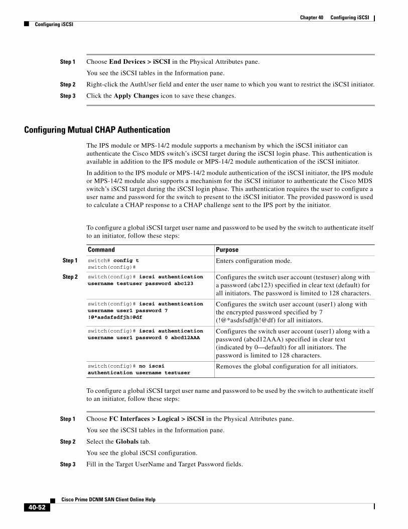
Chapter 40 Configuring iSCSIConfiguring iSCSI
Step 1 Choose End Devices > iSCSI in the Physical Attributes pane.
You see the iSCSI tables in the Information pane.
Step 2 Right-click the AuthUser field and enter the user name to which you want to restrict the iSCSI initiator.
Step 3 Click the Apply Changes icon to save these changes.
Configuring Mutual CHAP Authentication
The IPS module or MPS-14/2 module supports a mechanism by which the iSCSI initiator can authenticate the Cisco MDS switch’s iSCSI target during the iSCSI login phase. This authentication is available in addition to the IPS module or MPS-14/2 module authentication of the iSCSI initiator.
In addition to the IPS module or MPS-14/2 module authentication of the iSCSI initiator, the IPS module or MPS-14/2 module also supports a mechanism for the iSCSI initiator to authenticate the Cisco MDS switch’s iSCSI target during the iSCSI login phase. This authentication requires the user to configure a user name and password for the switch to present to the iSCSI initiator. The provided password is used to calculate a CHAP response to a CHAP challenge sent to the IPS port by the initiator.
To configure a global iSCSI target user name and password to be used by the switch to authenticate itself to an initiator, follow these steps:
To configure a global iSCSI target user name and password to be used by the switch to authenticate itself to an initiator, follow these steps:
Step 1 Choose FC Interfaces > Logical > iSCSI in the Physical Attributes pane.
You see the iSCSI tables in the Information pane.
Step 2 Select the Globals tab.
You see the global iSCSI configuration.
Step 3 Fill in the Target UserName and Target Password fields.
Command Purpose
Step 1 switch# config tswitch(config)#
Enters configuration mode.
Step 2 switch(config)# iscsi authentication username testuser password abc123
Configures the switch user account (testuser) along with a password (abc123) specified in clear text (default) for all initiators. The password is limited to 128 characters.
switch(config)# iscsi authentication username user1 password 7 !@*asdsfsdfjh!@df
Configures the switch user account (user1) along with the encrypted password specified by 7 (!@*asdsfsdfjh!@df) for all initiators.
switch(config)# iscsi authentication username user1 password 0 abcd12AAA
Configures the switch user account (user1) along with a password (abcd12AAA) specified in clear text (indicated by 0—default) for all initiators. The password is limited to 128 characters.
switch(config)# no iscsi authentication username testuser
Removes the global configuration for all initiators.
40-52Cisco Prime DCNM SAN Client Online Help

Chapter 40 Configuring iSCSIConfiguring iSCSI
Step 4 Click the Apply Changes icon to save these changes.
To configure a per-initiator iSCSI target’s user name and password used by the switch to authenticate itself to an initiator, follow these steps:
Use the show running-config and the show iscsi global commands to display the global configuration. Use the show running-config and the show iscsi initiator configured commands to display the initiator specific configuration.(See the “Displaying iSCSI User Information” section on page 40-93 for command output examples).
To configure a per-initiator iSCSI target’s user name and password used by the switch to authenticate itself to an initiator using Device Manager, follow these steps:
Step 1 Choose IP > iSCSI.
You see the iSCSI configuration.
Step 2 Complete the Target UserName and Target Password fields for the initiator that you want to configure.
Step 3 Click Create to add this initiator to the Initiator Access List.
Configuring an iSCSI RADIUS Server
To configure an iSCSI RADIUS server, follow these steps:
Step 1 Configure the RADIUS server to allow access from the Cisco MDS switch's management Ethernet IP address.
Step 2 Configure the shared secret for the RADIUS server to authenticate the Cisco MDS switch.
Step 3 Configure the iSCSI users and passwords on the RADIUS server.
Command Purpose
Step 1 switch# config tswitch(config)#
Enters configuration mode.
Step 2 switch(config)# iscsi initiator name iqn.1987-02.com.cisco.initiator switch(config-iscsi-init)#
Configures an iSCSI initiator using the iSCSI name of the initiator node.
Step 3 switch(config-iscsi-init)# mutual-chap username testuser password abcd12AAA
Configures the switch user account (testuser) along with a password (abcd12AAA) specified in clear text (default). The password is limited to 128 characters.
switch(config-iscsi-init)# mutual-chap username user1 password 7 !@*asdsfsdfjh!@df
Configures the switch user account (user1) along with the encrypted password specified by 7 (!@*asdsfsdfjh!@df).
switch(config-iscsi-init)# no mutual-chap username testuser
Removes the switch authentication configuration.
40-53Cisco Prime DCNM SAN Client Online Help
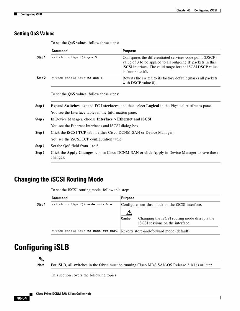
Chapter 40 Configuring iSCSIConfiguring iSLB
Setting QoS Values
To set the QoS values, follow these steps:
To set the QoS values, follow these steps:
Step 1 Expand Switches, expand FC Interfaces, and then select Logical in the Physical Attributes pane.
You see the Interface tables in the Information pane.
Step 2 In Device Manager, choose Interface > Ethernet and iSCSI.
You see the Ethernet Interfaces and iSCSI dialog box.
Step 3 Click the iSCSI TCP tab in either Cisco DCNM-SAN or Device Manager.
You see the iSCSI TCP configuration table.
Step 4 Set the QoS field from 1 to 6.
Step 5 Click the Apply Changes icon in Cisco DCNM-SAN or click Apply in Device Manager to save these changes.
Changing the iSCSI Routing ModeTo set the iSCSI routing mode, follow this step:
Configuring iSLB
Note For iSLB, all switches in the fabric must be running Cisco MDS SAN-OS Release 2.1(1a) or later.
This section covers the following topics:
Command Purpose
Step 1 switch(config-if)# qos 3 Configures the differentiated services code point (DSCP) value of 3 to be applied to all outgoing IP packets in this iSCSI interface. The valid range for the iSCSI DSCP value is from 0 to 63.
Step 2 switch(config-if)# no qos 5 Reverts the switch to its factory default (marks all packets with DSCP value 0).
Command Purpose
Step 1 switch(config-if)# mode cut-thru Configures cut-thru mode on the iSCSI interface.
Caution Changing the iSCSI routing mode disrupts the iSCSI sessions on the interface.
switch(config-if)# no mode cut-thru Reverts store-and-forward mode (default).
40-54Cisco Prime DCNM SAN Client Online Help
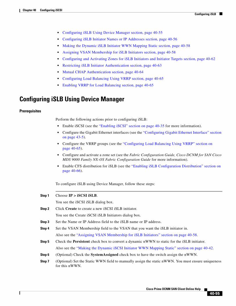
Chapter 40 Configuring iSCSIConfiguring iSLB
• Configuring iSLB Using Device Manager section, page 40-55
• Configuring iSLB Initiator Names or IP Addresses section, page 40-56
• Making the Dynamic iSLB Initiator WWN Mapping Static section, page 40-58
• Assigning VSAN Membership for iSLB Initiators section, page 40-58
• Configuring and Activating Zones for iSLB Initiators and Initiator Targets section, page 40-62
• Restricting iSLB Initiator Authentication section, page 40-63
• Mutual CHAP Authentication section, page 40-64
• Configuring Load Balancing Using VRRP section, page 40-65
• Enabling VRRP for Load Balancing section, page 40-65
Configuring iSLB Using Device Manager
Prerequisites
Perform the following actions prior to configuring iSLB:
• Enable iSCSI (see the “Enabling iSCSI” section on page 40-35 for more information).
• Configure the Gigabit Ethernet interfaces (see the “Configuring Gigabit Ethernet Interface” section on page 43-5).
• Configure the VRRP groups (see the “Configuring Load Balancing Using VRRP” section on page 40-65).
• Configure and activate a zone set (see the Fabric Configuration Guide, Cisco DCNM for SAN Cisco MDS 9000 Family NX-OS Fabric Configuration Guide for more information).
• Enable CFS distribution for iSLB (see the “Enabling iSLB Configuration Distribution” section on page 40-66).
To configure iSLB using Device Manager, follow these steps:
Step 1 Choose IP > iSCSI iSLB.
You see the iSCSI iSLB dialog box.
Step 2 Click Create to create a new iSCSI iSLB initiator.
You see the Create iSCSI iSLB Initiators dialog box.
Step 3 Set the Name or IP Address field to the iSLB name or IP address.
Step 4 Set the VSAN Membership field to the VSAN that you want the iSLB initiator in.
Also see the “Assigning VSAN Membership for iSLB Initiators” section on page 40-58.
Step 5 Check the Persistent check box to convert a dynamic nWWN to static for the iSLB initiator.
Also see the “Making the Dynamic iSCSI Initiator WWN Mapping Static” section on page 40-42.
Step 6 (Optional) Check the SystemAssigned check box to have the switch assign the nWWN.
Step 7 (Optional) Set the Static WWN field to manually assign the static nWWN. You must ensure uniqueness for this nWWN.
40-55Cisco Prime DCNM SAN Client Online Help
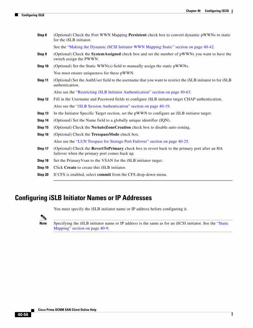
Chapter 40 Configuring iSCSIConfiguring iSLB
Step 8 (Optional) Check the Port WWN Mapping Persistent check box to convert dynamic pWWNs to static for the iSLB initiator.
See the “Making the Dynamic iSCSI Initiator WWN Mapping Static” section on page 40-42.
Step 9 (Optional) Check the SystemAssigned check box and set the number of pWWNs you want to have the switch assign the PWWN.
Step 10 (Optional) Set the Static WWN(s) field to manually assign the static pWWNs.
You must ensure uniqueness for these pWWN.
Step 11 (Optional) Set the AuthUser field to the username that you want to restrict the iSLB initiator to for iSLB authentication.
Also see the “Restricting iSLB Initiator Authentication” section on page 40-63.
Step 12 Fill in the Username and Password fields to configure iSLB initiator target CHAP authentication.
Also see the “iSLB Session Authentication” section on page 40-19.
Step 13 In the Initiator Specific Target section, set the pWWN to configure an iSLB initiator target.
Step 14 (Optional) Set the Name field to a globally unique identifier (IQN).
Step 15 (Optional) Check the NoAutoZoneCreation check box to disable auto-zoning.
Step 16 (Optional) Check the TresspassMode check box.
Also see the “LUN Trespass for Storage Port Failover” section on page 40-25.
Step 17 (Optional) Check the RevertToPrimary check box to revert back to the primary port after an HA failover when the primary port comes back up.
Step 18 Set the PrimaryVsan to the VSAN for the iSLB initiator target.
Step 19 Click Create to create this iSLB initiator.
Step 20 If CFS is enabled, select commit from the CFS drop-down menu.
Configuring iSLB Initiator Names or IP AddressesYou must specify the iSLB initiator name or IP address before configuring it.
Note Specifying the iSLB initiator name or IP address is the same as for an iSCSI initiator. See the “Static Mapping” section on page 40-9.
40-56Cisco Prime DCNM SAN Client Online Help

Chapter 40 Configuring iSCSIConfiguring iSLB
To enter iSLB initiator configuration submode using the name option for an iSLB initiator, follow these steps:
To enter iSLB initiator configuration submode using the ip-address option for an iSLB initiator, follow these steps:
Examples
To verify the iSLB initiator configuration, use the show islb initiator configured command.
switch# show islb initiator configurediSCSI Node name is 10.1.1.2 Member of vsans: 10 Node WWN is 23:02:00:0c:85:90:3e:82 Load Balance Metric: 100 Number of Initiator Targets: 1
Initiator Target: test-targt Port WWN 01:01:01:01:02:02:02:02 Primary PWWN VSAN 1 Zoning support is enabled Trespass support is disabled Revert to primary support is disabled
Command Purpose
Step 1 switch# config tswitch(config)#
Enters configuration mode.
Step 2 switch(config)# islb initiator name iqn.1987-02.com.cisco.initiatorswitch(config-islb-init)#
Configures an iSLB initiator using the iSCSI name of the initiator node (iqn.1987-02.com.cisco.initiator) and enters iSLB initiator configuration submode. The maximum name length is 223 alphanumeric characters. The minimum length is 16.
switch(config)# no lslb initiator name iqn.1987-02.com.cisco.initiator
Deletes the configured iSLB initiator.
Command Purpose
Step 1 switch# config terminalswitch(config)#
Enters configuration mode.
Step 2 switch(config)# islb initiator ip-address 10.1.1.3switch(config-islb-init)#
Configures an iSLB initiator using the IPv4 address of the initiator node and enters iSLB initiator configuration submode.
switch(config)# no islb initiator ip-address 10.1.1.3
Deletes the configured iSLB initiator.
switch(config)# islb initiator ip-address 2001:0DB8:800:200C::417Aswitch(config-islb-init)#
Configures an iSLB initiator using the IPv6 unicast address of the initiator node and enters iSLB initiator configuration submode.
switch(config)# no islb initiator ip-address 2001:0DB8:800:200C::417A
Deletes the configured iSLB initiator.
40-57Cisco Prime DCNM SAN Client Online Help
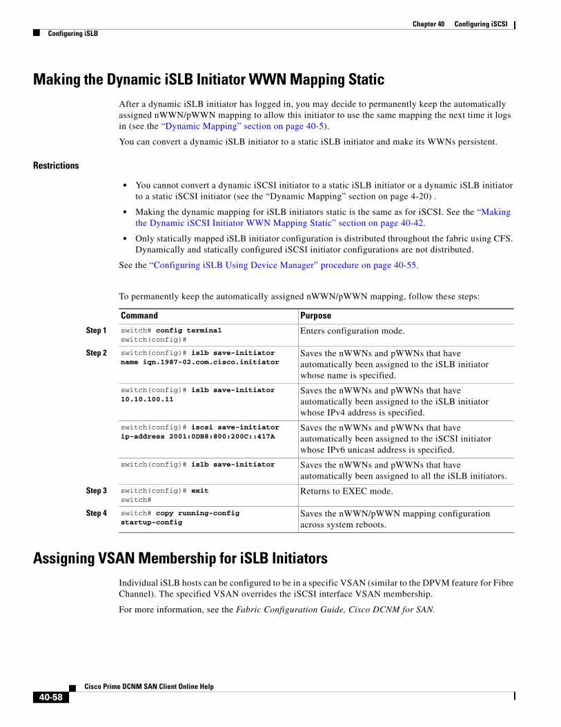
Chapter 40 Configuring iSCSIConfiguring iSLB
Making the Dynamic iSLB Initiator WWN Mapping StaticAfter a dynamic iSLB initiator has logged in, you may decide to permanently keep the automatically assigned nWWN/pWWN mapping to allow this initiator to use the same mapping the next time it logs in (see the “Dynamic Mapping” section on page 40-5).
You can convert a dynamic iSLB initiator to a static iSLB initiator and make its WWNs persistent.
Restrictions
• You cannot convert a dynamic iSCSI initiator to a static iSLB initiator or a dynamic iSLB initiator to a static iSCSI initiator (see the “Dynamic Mapping” section on page 4-20) .
• Making the dynamic mapping for iSLB initiators static is the same as for iSCSI. See the “Making the Dynamic iSCSI Initiator WWN Mapping Static” section on page 40-42.
• Only statically mapped iSLB initiator configuration is distributed throughout the fabric using CFS. Dynamically and statically configured iSCSI initiator configurations are not distributed.
See the “Configuring iSLB Using Device Manager” procedure on page 40-55.
To permanently keep the automatically assigned nWWN/pWWN mapping, follow these steps:
Assigning VSAN Membership for iSLB InitiatorsIndividual iSLB hosts can be configured to be in a specific VSAN (similar to the DPVM feature for Fibre Channel). The specified VSAN overrides the iSCSI interface VSAN membership.
For more information, see the Fabric Configuration Guide, Cisco DCNM for SAN.
Command Purpose
Step 1 switch# config terminalswitch(config)#
Enters configuration mode.
Step 2 switch(config)# islb save-initiator name iqn.1987-02.com.cisco.initiator
Saves the nWWNs and pWWNs that have automatically been assigned to the iSLB initiator whose name is specified.
switch(config)# islb save-initiator 10.10.100.11
Saves the nWWNs and pWWNs that have automatically been assigned to the iSLB initiator whose IPv4 address is specified.
switch(config)# iscsi save-initiator ip-address 2001:0DB8:800:200C::417A
Saves the nWWNs and pWWNs that have automatically been assigned to the iSCSI initiator whose IPv6 unicast address is specified.
switch(config)# islb save-initiator Saves the nWWNs and pWWNs that have automatically been assigned to all the iSLB initiators.
Step 3 switch(config)# exitswitch#
Returns to EXEC mode.
Step 4 switch# copy running-config startup-config
Saves the nWWN/pWWN mapping configuration across system reboots.
40-58Cisco Prime DCNM SAN Client Online Help

Chapter 40 Configuring iSCSIConfiguring iSLB
Note Specifying the iSLB initiator VSAN is the same as for an iSCSI initiator. See the “VSAN Membership for iSCSI” procedure on page 40-11.
To assign VSAN membership for iSLB initiators, follow these steps:
Note When an iSLB initiator is configured in any other VSAN (other than VSAN 1, the default VSAN), for example VSAN 2, the initiator is automatically removed from VSAN 1. If you also want it to be present in VSAN 1, you must explicitly configure the initiator in VSAN 1.
See the “Configuring iSLB Using Device Manager” procedure on page 40-55.
Configuring Metric for Load Balancing
You can assign a load metric to each initiator for weighted load balancing. The load calculated is based on the number of initiators on a given iSCSI interface. This feature accommodates initiators with different bandwidth requirements. For example, you could assign a higher load metric to a database server than to a web server. Weighted load balancing also accommodates initiators with different link speeds.
Also, you can configure initiator targets using the device alias or the pWWN. If you configure an IQN for an initiator target, then that name is used to identify the initiator target. Otherwise, a unique IQN is generated for the initiator target.
For more information on load balancing, see the “About Load Balancing Using VRRP” section on page 40-19.
Choose IP > iSCSI iSLB in Device Manager and set the LoadMetric field to change the load balancing metric for an iSLB initiator.
See the “Configuring iSLB Using Device Manager” procedure on page 40-55.
Command Purpose
Step 1 switch# config terminalswitch(config)#
Enters configuration mode.
Step 2 switch(config)# islb initiator ip-address 10.1.1.3switch(config-islb-init)#
Configures an iSLB initiator using its IPv4 address and enters iSLB initiator configuration submode.
Step 3 switch(config-islb-init)# vsan 3 Assigns the iSLB initiator node to a specified VSAN.
Note You can assign this host to one or more VSANs.
switch(config-islb-init)# no vsan 3 Removes the iSLB initiator from the specified VSAN.
40-59Cisco Prime DCNM SAN Client Online Help
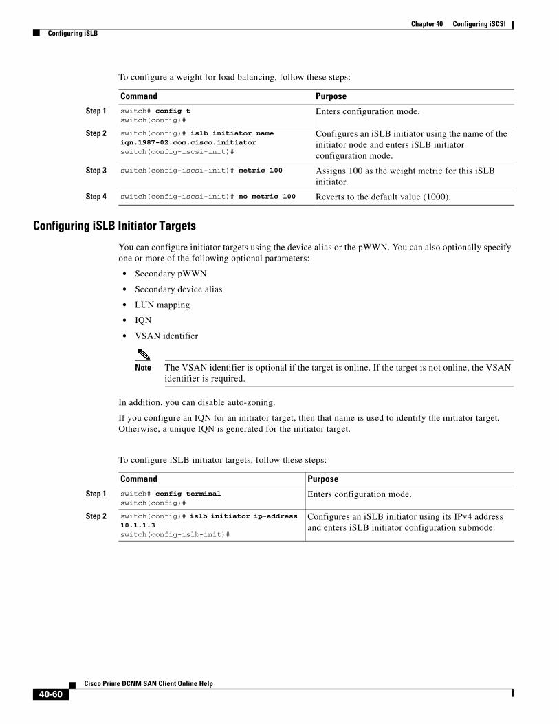
Chapter 40 Configuring iSCSIConfiguring iSLB
To configure a weight for load balancing, follow these steps:
Configuring iSLB Initiator Targets
You can configure initiator targets using the device alias or the pWWN. You can also optionally specify one or more of the following optional parameters:
• Secondary pWWN
• Secondary device alias
• LUN mapping
• IQN
• VSAN identifier
Note The VSAN identifier is optional if the target is online. If the target is not online, the VSAN identifier is required.
In addition, you can disable auto-zoning.
If you configure an IQN for an initiator target, then that name is used to identify the initiator target. Otherwise, a unique IQN is generated for the initiator target.
To configure iSLB initiator targets, follow these steps:
Command Purpose
Step 1 switch# config tswitch(config)#
Enters configuration mode.
Step 2 switch(config)# islb initiator name iqn.1987-02.com.cisco.initiator switch(config-iscsi-init)#
Configures an iSLB initiator using the name of the initiator node and enters iSLB initiator configuration mode.
Step 3 switch(config-iscsi-init)# metric 100 Assigns 100 as the weight metric for this iSLB initiator.
Step 4 switch(config-iscsi-init)# no metric 100 Reverts to the default value (1000).
Command Purpose
Step 1 switch# config terminalswitch(config)#
Enters configuration mode.
Step 2 switch(config)# islb initiator ip-address 10.1.1.3switch(config-islb-init)#
Configures an iSLB initiator using its IPv4 address and enters iSLB initiator configuration submode.
40-60Cisco Prime DCNM SAN Client Online Help

Chapter 40 Configuring iSCSIConfiguring iSLB
To configure additional iSLB initiator targets using Device Manager, follow these steps:
Step 1 Choose IP > iSCSI iSLB.
You see the iSCSI iSLB dialog box.
Step 2 Click on the initiator you want to add targets to and click Edit Initiator Specific Targets.
You see the Initiator Specific Target dialog box.
Step 3 Click Create to create a new initiator target.
You see the Create Initiator Specific Target dialog box.
Step 4 Fill in the pWWN field with the initiator target pWWN.
Step 5 (Optional) Set the Name field to a globally unique identifier (IQN).
Step 6 (Optional) Check the NoAutoZoneCreation check box to disable auto-zoning.
Step 7 (Optional) Check the TresspassMode check box. See the “LUN Trespass for Storage Port Failover” section on page 40-25.
Step 8 (Optional) Check the RevertToPrimary check box to revert back to the primary port after an HA failover when the primary port comes back up.
Step 9 Set the PrimaryVsan to the VSAN for the iSLB initiator target.
Step 3 switch(config-iscsi-islb-init)# target pwwn 26:00:01:02:03:04:05:06
Configures the iSLB initiator target using a pWWN with auto-zoning enabled (default).
switch(config-iscsi-islb-init)# target pwwn 26:00:01:02:03:04:05:06 no-zone
Configures the iSLB initiator target using a pWWN with auto-zoning disabled.
switch(config-iscsi-islb-init)# target device-alias SampleAlias
Configures the iSLB initiator target using a device alias with auto-zoning enabled (default).
switch(config-iscsi-islb-init)# target device-alias SampleAlias fc-lun 0x1234 iscsi-lun 0x2345
Configures the iSLB initiator target using a device alias and optional LUN mapping.
Note The CLI interprets the LUN identifier value as a hexadecimal value whether or not the 0x prefix is included.
switch(config-iscsi-islb-init)# target device-alias SampleAlias iqn-name iqn.1987-01.com.cisco.initiator
Configures the iSLB initiator target using a device alias and an optional IQN.
switch(config-iscsi-islb-init)# target device-alias SampleAlias sec-device-alias SecondaryAlias
Configures the iSLB initiator target using a device alias and an optional secondary device alias.
switch(config-iscsi-islb-init)# target device-alias SampleAlias sec-pwwn 26:01:02:03:04:05:06:07
Configures the iSLB initiator target using a device alias and an optional secondary pWWN.
switch(config-iscsi-islb-init)# target device-alias SampleAlias vsan 10
Configures the iSLB initiator target using a device alias and the VSAN identifier.
Note The VSAN identifier is optional is if the target is online. If the target is not online, the VSAN identifier is required.
switch(config-iscsi-init)# no target pwwn 26:00:01:02:03:04:05:06
Removes the iSLB initiator target.
Command Purpose
40-61Cisco Prime DCNM SAN Client Online Help
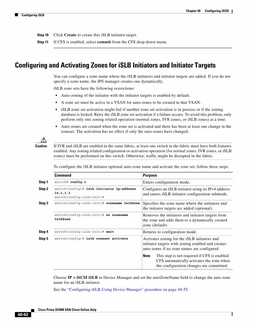
Chapter 40 Configuring iSCSIConfiguring iSLB
Step 10 Click Create to create this iSLB initiator target.
Step 11 If CFS is enabled, select commit from the CFS drop-down menu.
Configuring and Activating Zones for iSLB Initiators and Initiator TargetsYou can configure a zone name where the iSLB initiators and initiator targets are added. If you do not specify a zone name, the IPS manager creates one dynamically.
iSLB zone sets have the following restrictions:
• Auto-zoning of the initiator with the initiator targets is enabled by default.
• A zone set must be active in a VSAN for auto-zones to be created in that VSAN.
• iSLB zone set activation might fail if another zone set activation is in process or if the zoning database is locked. Retry the iSLB zone set activation if a failure occurs. To avoid this problem, only perform only one zoning related operation (normal zones, IVR zones, or iSLB zones) at a time.
• Auto-zones are created when the zone set is activated and there has been at least one change in the zoneset. The activation has no effect if only the auto-zones have changed.
Caution If IVR and iSLB are enabled in the same fabric, at least one switch in the fabric must have both features enabled. Any zoning related configuration or activation operation (for normal zones, IVR zones, or iSLB zones) must be performed on this switch. Otherwise, traffic might be disrupted in the fabric.
To configure the iSLB initiator optional auto-zone name and activate the zone set, follow these steps:
Choose IP > iSCSI iSLB in Device Manager and set the autoZoneName field to change the auto zone name for an iSLB initiator.
See the “Configuring iSLB Using Device Manager” procedure on page 40-55.
Command Purpose
Step 1 switch# config t Enters configuration mode.
Step 2 switch(config)# islb initiator ip-address 10.1.1.3switch(config-islb-init)#
Configures an iSLB initiator using its IPv4 address and enters iSLB initiator configuration submode.
Step 3 switch(config-islb-init)# zonename IslbZone Specifies the zone name where the initiators and the initiator targets are added (optional).
switch(config-islb-init)# no zonename IslbZone
Removes the initiators and initiator targets from the zone and adds them to a dynamically created zone (default).
Step 4 switch(config-islb-init)# exit Returns to configuration mode.
Step 5 switch(config)# islb zoneset activate Activates zoning for the iSLB initiators and initiator targets with zoning enabled and creates auto-zones if no zone names are configured.
Note This step is not required if CFS is enabled. CFS automatically activates the zone when the configuration changes are committed.
40-62Cisco Prime DCNM SAN Client Online Help

Chapter 40 Configuring iSCSIConfiguring iSLB
Examples
The following example shows the show zoneset active command output when the dynamically generated zone name is used.
switch# show zoneset activezoneset name zoneset-1 vsan 1 zone name ips_zone_5d9603bcff68008a6fc5862a6670ca09 vsan 1 * fcid 0x010009 [ip-address 10.1.1.3] pwwn 22:00:00:04:cf:75:28:4d pwwn 22:00:00:04:cf:75:ed:53 pwwn 22:00:00:04:cf:75:21:d5 pwwn 22:00:00:04:cf:75:ee:59...
The following example shows the show zoneset active command output when the configured zone name IslbZone is used.
switch# show zoneset activezoneset name zoneset-1 vsan 1 zone name ips_zone_IslbZone vsan 1 ip-address 10.1.1.3 pwwn 22:00:00:04:cf:75:28:4d pwwn 22:00:00:04:cf:75:ed:53 pwwn 22:00:00:04:cf:75:21:d5 pwwn 22:00:00:04:cf:75:ee:59...
Restricting iSLB Initiator Authentication By default, the iSLB initiator can use any user name in the RADIUS or local AAA database in authenticating itself to the IPS module or MPS-14/2 module (the CHAP user name is independent of the iSLB initiator name). The IPS module or MPS-14/2 module allows the initiator to log in as long as it provides a correct response to the CHAP challenge sent by the switch. This can be a problem if one CHAP user name and password have been compromised.
To restrict an initiator to use a specific user name for CHAP authentication, follow these steps:
Choose IP > iSCSI iSLB in Device Manager and set the AuthName field to restrict an initiator to use a specific user name for CHAP authentication.
See the “Configuring iSLB Using Device Manager” procedure on page 40-55.
Command Purpose
Step 1 switch# config tswitch(config)#
Enters configuration mode.
Step 2 switch(config)# islb initiator name iqn.1987-02.com.cisco.initswitch(config-islb-init)#
Configures an iSLB initiator using the IQN of the initiator node and enters iSLB initiator configuration mode.
Step 3 switch(config-islb-init)# username user1
Restricts the initiator iqn.1987-02.com.cisco.init to only authenticate using user1 as its CHAP user name.
Tip Be sure to define user1 as an iSCSI user in the local AAA database or the RADIUS server.
40-63Cisco Prime DCNM SAN Client Online Help

Chapter 40 Configuring iSCSIConfiguring iSLB
Mutual CHAP Authentication In addition to the IPS module and MPS-14/2 module authentication of the iSLB initiator, the IPS module and MPS-14/2 module also support a mechanism for the iSLB initiator to authenticate the Cisco MDS switch’s initiator target during the iSCSI login phase. This authentication requires the user to configure a user name and password for the switch to present to the iSLB initiator. The provided password is used to calculate a CHAP response to a CHAP challenge sent to the IPS port by the initiator.
To configure a per-initiator user name and password used by the switch to authenticate itself to an initiator, follow these steps:
Choose IP > iSCSI iSLB in Device Manager and set the Target Username and Target Password fields to configure a per-initiator user name and password used by the switch to authenticate itself to an initiator.
See the “Configuring iSLB Using Device Manager” procedure on page 40-55.
Examples
Use the show running-config and the show iscsi global (see Example 40-6) commands to display the global configuration. Use the show running-config and the show islb initiator configured (see Example 40-14) commands to display the initiator specific configuration.
To verify the iSLB user name and mutual CHAP configuration, use the show islb initiator configured command.
switch# show islb initiator configurediSCSI Node name is 10.1.1.3 Member of vsans: 3 User Name for login authentication: user1 User Name for Mutual CHAP: testuser Load Balance Metric: 1000 Number of Initiator Targets: 1 Number of Initiator Targets: 1
Initiator Target: iqn.1987-05.com.cisco:05.ips-hac4 Port WWN 50:06:04:82:ca:e1:26:8d Zoning Enabled No. of LU mapping: 3 iSCSI LUN: 0x0001, FC LUN: 0x0001
Command Purpose
Step 1 switch# config tswitch(config)#
Enters configuration mode.
Step 2 switch(config)# islb initiator name iqn.1987-02.com.cisco.initiator switch(config-islb-init)#
Configures an iSLB initiator using the name of the initiator node and enters iSLB initiator configuration mode.
Step 3 switch(config-islb-init)# mutual-chap username testuser password dcba12LKJ
Configures the switch user account (testuser) along with a password (dcba12LKJ) specified in clear text (default). The password is limited to 128 characters.
switch(config-islb-init)# mutual-chap username testuser password 7 !@*asdsfsdfjh!@df
Configures the switch user account (testuser) along with the encrypted password specified by 7 (!@*asdsfsdfjh!@df).
Step 4 switch(config-iscsi-init)# no mutual-chap username testuser
Removes the switch authentication configuration.
40-64Cisco Prime DCNM SAN Client Online Help

Chapter 40 Configuring iSCSIConfiguring iSLB
iSCSI LUN: 0x0002, FC LUN: 0x0002 iSCSI LUN: 0x0003, FC LUN: 0x0003
Configuring Load Balancing Using VRRPYou must first configure VRRP on the Gigabit Ethernet interfaces on the switch that connect to the IP network before configuring VRRP for iSLB.
To configure VRRP load balancing using Device Manager, follow these steps:
Step 1 Choose IP > iSCSI iSLB.
You see the iSCSI iSLB dialog box.
Step 2 Click the VRRP tab.
Step 3 Click Create to configure VRRP load balancing for iSLB initiators.
You see the Create iSCSI iSLB VRRP dialog box.
Step 4 Set the Vrld to the VRRP group number.
Step 5 Select either ipv4 or ipv6 and check the LoadBalance check box.
Step 6 Click Create to enable load balancing.
Step 7 If CFS is enabled, select commit from the CFS drop-down menu.
Enabling VRRP for Load BalancingTo enable or disable VRRP for iSLB, follow these steps:
Examples
To verify the iSLB VRRP load balancing configuration for IPv4, use the show vrrp vr command.
switch# show vrrp vr 1 Interface VR IpVersion Pri Time Pre State VR IP addr--------------------------------------------------------------------------- GigE1/5 1 IPv4 100 1 s master 10.10.10.1 GigE1/6 1 IPv4 100 1 s master 10.10.10.1
To verify the iSLB VRRP load balancing configuration for IPv6, use the show vrrp ipv6 vr command.
Command Purpose
Step 1 switch# config tswitch(config)#
Enters configuration mode.
Step 2 switch(config)# islb vrrp 10 load-balance Enables iSLB VRRP for IPv4 VR group 10.
Step 3 switch(config)# no islb vrrp 10 load-balance Disables iSLB VRRP for IPv4 VR group 10.
Step 4 switch(config)# islb vrrp ipv6 20 load-balance
Enables iSLB VRRP for IPv6 VR group 20.
Step 5 switch(config)# no islb vrrp ipv6 20 load-balance
Disables iSLB VRRP for IPv6 VR group 20.
40-65Cisco Prime DCNM SAN Client Online Help

Chapter 40 Configuring iSCSIDistributing the iSLB Configuration Using CFS
switch# show vrrp ipv6 vr 1 Interface VR IpVersion Pri Time Pre State VR IP addr-------------------------------------------------------------------- GigE6/2 1 IPv6 100 100cs master 5000:1::100 PortCh 4 1 IPv6 100 100cs master 5000:1::100
Distributing the iSLB Configuration Using CFSThis section contains the following:
• Enabling iSLB Configuration Distribution section, page 40-66
• Committing Changes to the Fabric section, page 40-66
• Discarding Pending Changes section, page 40-67
• Clearing a Fabric Lock section, page 40-67
• Creating a Static iSCSI Virtual Target section, page 40-68
• Enabling the Trespass Feature for a Static iSCSI section, page 40-69
Enabling iSLB Configuration DistributionTo enable CFS distribution of the iSLB configuration, follow these steps:
To enable CFS distribution of the iSLB configuration using Device Manager, follow these steps:
Step 1 Choose Admin > CFS.
You see the CFS dialog box.
Step 2 Set the Command field to enable for the iSLB feature.
Step 3 Click Apply to save this change.
Committing Changes to the FabricTo apply the pending iSLB configuration changes to the active configuration and to other MDS switches in the fabric, you must commit the changes. The pending configuration changes are distributed and, on a successful commit, the configuration changes are applied to the active configuration in the MDS switches throughout the fabric, the automatic zones are activated, and the fabric lock is released.
Command Purpose
Step 1 switch# config t Enters configuration mode.
Step 2 switch(config)# islb distribute Enables iSLB configuration distribution.
switch(config)# no islb distribute Disables (default) iSLB configuration distribution.
40-66Cisco Prime DCNM SAN Client Online Help

Chapter 40 Configuring iSCSIDistributing the iSLB Configuration Using CFS
To commit iSLB configuration changes to other MDS switches in the fabric, activate iSLB automatic zones, and release the fabric lock, follow these steps:
To commit iSLB configuration changes to other MDS switches in the fabric, activate iSLB automatic zones, and release the fabric lock using Device Manager, follow these steps:
Step 1 Choose Admin > CFS.
You see the CFS Configuration dialog box.
Step 2 Set the Command field to commit for the iSLB feature.
Step 3 Click Apply to save this change.
Discarding Pending ChangesAt any time, you can discard the pending changes to the iSLB configuration and release the fabric lock. This action has no affect on the active configuration on any switch in the fabric.
To discard the pending iSLB configuration changes and release the fabric lock, follow these steps:
To discard the pending iSLB configuration changes and release the fabric lock using Device Manager, follow these steps:
Step 1 Choose Admin > CFS.
You see the CFS Configuration dialog box.
Step 2 Set the Command field to abort for the iSLB feature.
Step 3 Click Apply to save this change.
Clearing a Fabric LockIf you have performed an iSLB configuration task and have not released the lock by either committing or discarding the changes, an administrator can release the lock from any switch in the fabric. If the administrator performs this task, your pending changes are discarded and the fabric lock is released.
Command Purpose
Step 1 switch# config t Enters configuration mode.
Step 2 switch(config)# islb commit Commits the iSLB configuration distribution, activates iSLB automatic zones, and releases the fabric lock.
Command Purpose
Step 1 switch# config t Enters configuration mode.
Step 2 switch(config)# islb abort Commits the iSLB configuration distribution.
40-67Cisco Prime DCNM SAN Client Online Help

Chapter 40 Configuring iSCSIDistributing the iSLB Configuration Using CFS
Restrictions
The pending changes are only available in the volatile directory and are discarded if the switch is restarted.
To release a fabric lock, issue the clear islb session command in EXEC mode using a login ID that has administrative privileges.
switch# clear islb session
To release a fabric lock using Device Manager, follow these steps:
Step 1 Choose Admin > CFS.
You see the CFS Configuration dialog box.
Step 2 Set the Command field to clear for the iSLB feature.
Step 3 Click Apply to save this change.
Creating a Static iSCSI Virtual TargetTo create a static iSCSI virtual target, follow these steps:
Command Purpose
Step 1 switch# config terminalswitch(config)#
Enters configuration mode.
Step 2 switch(config)# iscsi virtual-target name iqn.1987-02.com.cisco.initiator
Creates the iSCSI target name iqn.1987-02.com.cisco.initiator.
Step 3 switch(config-iscsi-tgt)# pwwn 26:00:01:02:03:04:05:06 Configures the primary port for this virtual target.
switch(config-iscsi-tgt)# pwwn 26:00:01:02:03:04:05:06 secondary-pwwn 26:00:01:02:03:10:11:12
Configures the primary and secondary ports for this virtual target.
switch(config-iscsi-tgt)# pwwn 26:00:01:02:03:04:05:06 fc-lun 0x1 iscsi-lun 0x0 sec-lun 0x3
Configures the primary port for this virtual target with LUN mapping and different LUN on the secondary Fibre Channel port.
Note The CLI interprets the LUN identifier value as a hexadecimal value whether or not the 0x prefix is included.
switch(config-iscsi-tgt)# no pwwn 26:00:01:02:03:04:05:06 Removes the primary port, secondary port, and LUN mapping configuration for this virtual target.
40-68Cisco Prime DCNM SAN Client Online Help

Chapter 40 Configuring iSCSIDistributing the iSLB Configuration Using CFS
To create a static iSCSI virtual target for the entire Fibre Channel target port using Device Manager, follow these steps:
Step 1 Click IP > iSCSI.
You see the iSCSI configuration.
Step 2 Click the Targets tab to display a list of existing iSCSI targets shown.
Step 3 Click Create to create an iSCSI target.
You see the Create iSCSI Targets dialog box.
Step 4 Set the iSCSI target node name in the iSCSI Name field, in IQN format.
Step 5 Set the Port WWN field for the Fibre Channel target port you are mapping.
Step 6 Click the Select from List radio button and set the iSCSI initiator node names or IP addresses that you want this virtual iSCSI target to access, or click the All radio button to let the iSCSI target access all iSCSI initiators. See the “iSCSI Access Control” section on page 40-11.
Step 7 Chick the Select from List radio button and check each interface you want to advertise the iSCSI targets on or choose the All radio button to advertise all interfaces.
Step 8 Click Apply to save this change.
Enabling the Trespass Feature for a Static iSCSITo enable the trespass feature for a static iSCSI virtual target, follow these steps:
Step 4 switch(config-iscsi-tgt)# revert-primary-port Configures the session failover redundancy for this virtual-target to switch all sessions back to primary port when the primary port comes back up.
Step 5 switch(config-iscsi-tgt)# no revert-primary-port Directs the switch to continue using the secondary port for existing sessions and to use the primary port for new sessions (default).
Command Purpose
Command Purpose
Step 1 switch# config terminalswitch(config)#
Enters configuration mode.
Step 2 switch(config)# iscsi virtual-target name iqn.1987-02.com.cisco.initiatorswitch(config-iscsi-tgt)#
Creates the iSCSI target name iqn.1987-02.com.cisco.initiator.
Step 3 switch(config-iscsi-tgt)# pwwn 50:00:00:a1:94:cc secondary-pwwn 50:00:00:a1:97:ac
Maps a virtual target node to a Fibre Channel target and configures a secondary pWWN.
Step 4 switch(config-iscsi-tgt)# trespass Enables the trespass feature.
switch(config-iscsi-tgt)# no trespass Disables the trespass feature (default).
40-69Cisco Prime DCNM SAN Client Online Help

Chapter 40 Configuring iSCSIConfiguring iSCSI Authentication
In Device Manager, choose IP > iSCSI, select the Targets tab, and check the Trespass Mode check box to enable the trespass feature for a static iSCSI virtual target.
switch# show iscsi virtual-target iqn.1987-02.com.cisco.initiatortarget: 1987-02.com.cisco.initiator Port WWN 10:20:10:00:56:00:70:50 Configured node all initiator permit is disabled trespass support is enabled
Configuring iSCSI AuthenticationThis section provides configuration information on iSCSI authenticatio. It includes the following authentication procedures:
• Configuring No Authentication section, page 40-70
• Configuring CHAP with Local Password Database section, page 40-70
• Configuring CHAP with External RADIUS Server section, page 40-71
Note This section does not specify the steps to enter or exit EXEC mode, configuration mode, or any submode. Be sure to verify the prompt before entering any command.
Caution Changing the authentication of an iSCSI interface that is part of an iSLB VRRP group impacts load balancing on the interface. See the “Changing iSCSI Interface Parameters and the Impact on Load Balancing” section on page 40-21.
Configuring No AuthenticationTo configure a network with no authentication, set the iSCSI authentication method to none
In Cisco DCNM-SAN, choose End Devices > iSCSI in the Physical Attributes pane. Select the Globals tab and set the AuthMethod drop-down menu to none and click Apply Changes.
switch(config)# iscsi authentication none
Configuring CHAP with Local Password DatabaseTo configure authentication using the CHAP option with the local password database, follow these steps:
Step 1 Set the AAA authentication to use the local password database for the iSCSI protocol.
switch(config)# aaa authentication iscsi default local
Step 2 Set the iSCSI authentication method to require CHAP for all iSCSI clients.
switch(config)# iscsi authentication chap
Step 3 Configure the user names and passwords for iSCSI users.
40-70Cisco Prime DCNM SAN Client Online Help

Chapter 40 Configuring iSCSIConfiguring iSCSI Authentication
switch(config)# username iscsi-user password abcd iscsi
Note If you do not specify the iscsi option, the user name is assumed to be a Cisco MDS switch user instead of an iSCSI user.
Step 4 Verify the global iSCSI authentication setup.
switch# show iscsi global iSCSI Global information Authentication: CHAP <----Verify Import FC Target: Disabled ...
To configure authentication using the CHAP option with the local password database, follow these steps:
Step 1 Set the AAA authentication to use the local password database for the iSCSI protocol:
a. In Cisco DCNM-SAN, choose Switches > Security > AAA in the Physical Attributes pane.
b. Click the Applications tab in the Information pane.
c. Check the Local check box for the iSCSI row and click Apply Changes
Step 2 Set the iSCSI authentication method to require CHAP for all iSCSI clients:
a. In Cisco DCNM-SAN, choose End Devices > iSCSI in the Physical Attributes pane.
b. Click the Globals tab in the Information pane.
c. Set the AuthMethod drop-down menu to chap and click Apply Changes.
Step 3 Configure the user names and passwords for iSCSI users:
a. In Device Manager, choose Security > iSCSI.
b. Set the Username, Password and Confirm Password fields.
c. Click Create to save these changes.
Step 4 Verify the global iSCSI authentication setup:
a. In Cisco DCNM-SAN, choose End Devices > iSCSI in the Physical Attributes pane.
b. Click the Globals tab in the Information pane.
Configuring CHAP with External RADIUS ServerTo configure authentication using the CHAP option with an external RADIUS server, follow these steps:
Step 1 Configure the password for the Cisco MDS switch as RADIUS client to the RADIUS server
switch(config)# radius-server key mds-1
Step 2 Configure the RADIUS server IP address by performing one of the following:
• Configure an IPv4 address.
switch(config)# radius-server host 10.1.1.10
40-71Cisco Prime DCNM SAN Client Online Help
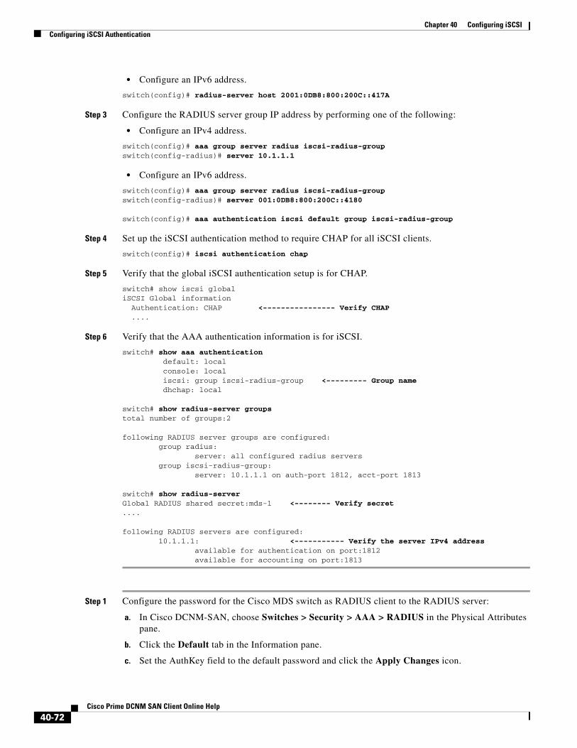
Chapter 40 Configuring iSCSIConfiguring iSCSI Authentication
• Configure an IPv6 address.
switch(config)# radius-server host 2001:0DB8:800:200C::417A
Step 3 Configure the RADIUS server group IP address by performing one of the following:
• Configure an IPv4 address.
switch(config)# aaa group server radius iscsi-radius-groupswitch(config-radius)# server 10.1.1.1
• Configure an IPv6 address.
switch(config)# aaa group server radius iscsi-radius-groupswitch(config-radius)# server 001:0DB8:800:200C::4180
switch(config)# aaa authentication iscsi default group iscsi-radius-group
Step 4 Set up the iSCSI authentication method to require CHAP for all iSCSI clients.
switch(config)# iscsi authentication chap
Step 5 Verify that the global iSCSI authentication setup is for CHAP.
switch# show iscsi global iSCSI Global information Authentication: CHAP <---------------- Verify CHAP ....
Step 6 Verify that the AAA authentication information is for iSCSI.
switch# show aaa authentication default: local console: local iscsi: group iscsi-radius-group <--------- Group name dhchap: local
switch# show radius-server groups total number of groups:2
following RADIUS server groups are configured: group radius: server: all configured radius servers group iscsi-radius-group: server: 10.1.1.1 on auth-port 1812, acct-port 1813
switch# show radius-server Global RADIUS shared secret:mds-1 <-------- Verify secret....
following RADIUS servers are configured: 10.1.1.1: <----------- Verify the server IPv4 address available for authentication on port:1812 available for accounting on port:1813
Step 1 Configure the password for the Cisco MDS switch as RADIUS client to the RADIUS server:
a. In Cisco DCNM-SAN, choose Switches > Security > AAA > RADIUS in the Physical Attributes pane.
b. Click the Default tab in the Information pane.
c. Set the AuthKey field to the default password and click the Apply Changes icon.
40-72Cisco Prime DCNM SAN Client Online Help

Chapter 40 Configuring iSCSIConfiguring iSCSI Authentication
Step 2 Configure the RADIUS server IP address:
a. In Cisco DCNM-SAN, choose Switches > Security > AAA > RADIUS in the Physical Attributes pane.
b. Click the Server tab in the Information pane and click Create Row.
c. Set the Index field to a unique number.
d. Set the IP Type radio button to ipv4 or ipv6.
e. Set the Name or IP Address field to the IP address of the RADIUS server and click Create.
Step 3 Create a RADIUS server group and add the RADIUS server to the group:
a. In Cisco DCNM-SAN, choose Switches > Security > AAA in the Physical Attributes pane.
b. Select the Server Groups tab in the Information pane and click Create Row.
c. Set the Index field to a unique number.
d. Set the Protocol radio button to radius.
e. Set the Name field to the server group name.
f. Set the ServerIDList to the index value of the RADIUS server (as created in Step 2 c.) and click Create.
Step 4 Set up the authentication verification for the iSCSI protocol to go to the RADIUS server.
a. In Cisco DCNM-SAN, choose Switches > Security > AAA in the Physical Attributes pane.
b. Click the Applications tab in the Information pane.
c. Right-click on the iSCSI row in the Type, SubType, Function column.
d. Set the ServerGroup IDList to the index value of the Server Group (as created in Step 3 c) and click Create.
Step 5 Set up the iSCSI authentication method to require CHAP for all iSCSI clients.
a. In Cisco DCNM-SAN, choose End Devices > iSCSI in the Physical Attributes pane.
b. Select chap from the AuthMethod drop-down menu.
c. Click the Apply Changes icon.
Step 6 In Cisco DCNM-SAN, choose End Devices > iSCSI in the Physical Attributes pane.
Step 7 Click the Globals tab in the Information pane to verify that the global iSCSI authentication setup is for CHAP.
Step 8 In Cisco DCNM-SAN, choose Switches > Security > AAA in the Physical Attributes pane.
Step 9 Click the Applications tab in the Information pane to verify the AAA authentication information for iSCSI.
To configure an iSCSI RADIUS server, follow these steps:
Step 1 Configure the RADIUS server to allow access from the Cisco MDS switch's management Ethernet IP address.
Step 2 Configure the shared secret for the RADIUS server to authenticate the Cisco MDS switch.
Step 3 Configure the iSCSI users and passwords on the RADIUS server.
40-73Cisco Prime DCNM SAN Client Online Help
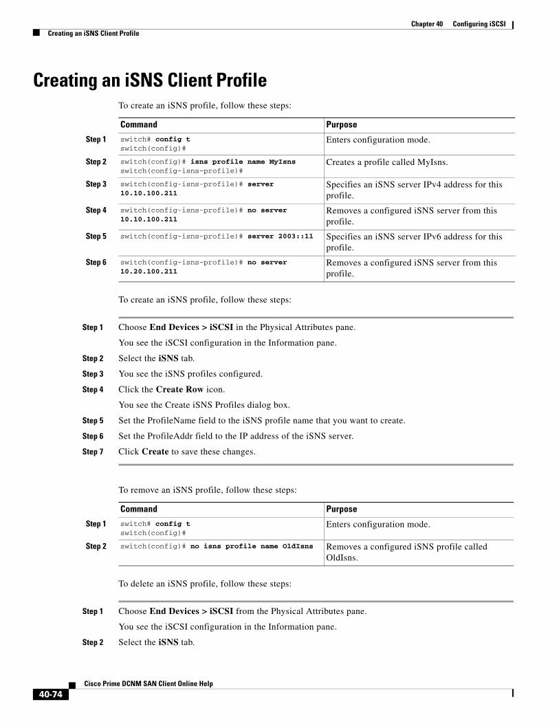
Chapter 40 Configuring iSCSICreating an iSNS Client Profile
Creating an iSNS Client ProfileTo create an iSNS profile, follow these steps:
To create an iSNS profile, follow these steps:
Step 1 Choose End Devices > iSCSI in the Physical Attributes pane.
You see the iSCSI configuration in the Information pane.
Step 2 Select the iSNS tab.
Step 3 You see the iSNS profiles configured.
Step 4 Click the Create Row icon.
You see the Create iSNS Profiles dialog box.
Step 5 Set the ProfileName field to the iSNS profile name that you want to create.
Step 6 Set the ProfileAddr field to the IP address of the iSNS server.
Step 7 Click Create to save these changes.
To remove an iSNS profile, follow these steps:
To delete an iSNS profile, follow these steps:
Step 1 Choose End Devices > iSCSI from the Physical Attributes pane.
You see the iSCSI configuration in the Information pane.
Step 2 Select the iSNS tab.
Command Purpose
Step 1 switch# config tswitch(config)#
Enters configuration mode.
Step 2 switch(config)# isns profile name MyIsnsswitch(config-isns-profile)#
Creates a profile called MyIsns.
Step 3 switch(config-isns-profile)# server 10.10.100.211
Specifies an iSNS server IPv4 address for this profile.
Step 4 switch(config-isns-profile)# no server 10.10.100.211
Removes a configured iSNS server from this profile.
Step 5 switch(config-isns-profile)# server 2003::11 Specifies an iSNS server IPv6 address for this profile.
Step 6 switch(config-isns-profile)# no server 10.20.100.211
Removes a configured iSNS server from this profile.
Command Purpose
Step 1 switch# config tswitch(config)#
Enters configuration mode.
Step 2 switch(config)# no isns profile name OldIsns Removes a configured iSNS profile called OldIsns.
40-74Cisco Prime DCNM SAN Client Online Help
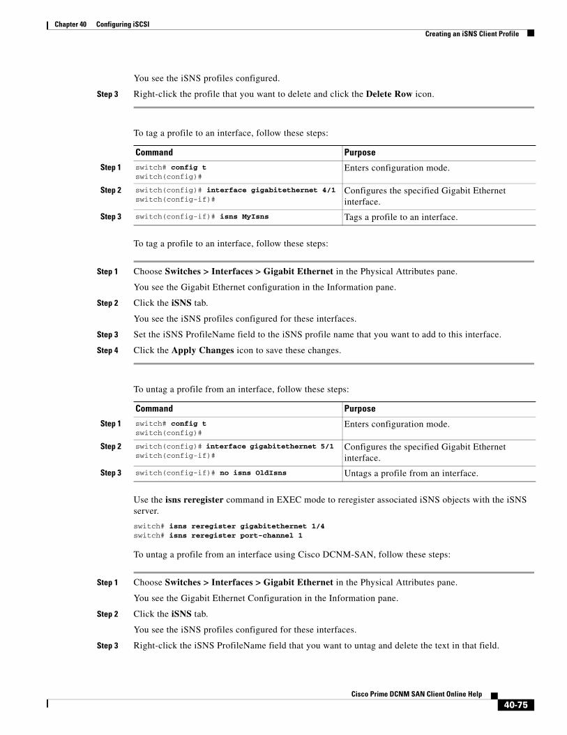
Chapter 40 Configuring iSCSICreating an iSNS Client Profile
You see the iSNS profiles configured.
Step 3 Right-click the profile that you want to delete and click the Delete Row icon.
To tag a profile to an interface, follow these steps:
To tag a profile to an interface, follow these steps:
Step 1 Choose Switches > Interfaces > Gigabit Ethernet in the Physical Attributes pane.
You see the Gigabit Ethernet configuration in the Information pane.
Step 2 Click the iSNS tab.
You see the iSNS profiles configured for these interfaces.
Step 3 Set the iSNS ProfileName field to the iSNS profile name that you want to add to this interface.
Step 4 Click the Apply Changes icon to save these changes.
To untag a profile from an interface, follow these steps:
Use the isns reregister command in EXEC mode to reregister associated iSNS objects with the iSNS server.
switch# isns reregister gigabitethernet 1/4switch# isns reregister port-channel 1
To untag a profile from an interface using Cisco DCNM-SAN, follow these steps:
Step 1 Choose Switches > Interfaces > Gigabit Ethernet in the Physical Attributes pane.
You see the Gigabit Ethernet Configuration in the Information pane.
Step 2 Click the iSNS tab.
You see the iSNS profiles configured for these interfaces.
Step 3 Right-click the iSNS ProfileName field that you want to untag and delete the text in that field.
Command Purpose
Step 1 switch# config tswitch(config)#
Enters configuration mode.
Step 2 switch(config)# interface gigabitethernet 4/1switch(config-if)#
Configures the specified Gigabit Ethernet interface.
Step 3 switch(config-if)# isns MyIsns Tags a profile to an interface.
Command Purpose
Step 1 switch# config tswitch(config)#
Enters configuration mode.
Step 2 switch(config)# interface gigabitethernet 5/1 switch(config-if)#
Configures the specified Gigabit Ethernet interface.
Step 3 switch(config-if)# no isns OldIsns Untags a profile from an interface.
40-75Cisco Prime DCNM SAN Client Online Help
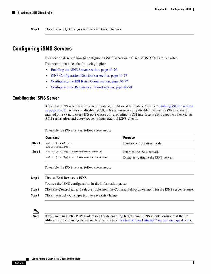
Chapter 40 Configuring iSCSICreating an iSNS Client Profile
Step 4 Click the Apply Changes icon to save these changes.
Configuring iSNS ServersThis section describe how to configure an iSNS server on a Cisco MDS 9000 Family switch.
This section includes the following topics:
• Enabling the iSNS Server section, page 40-76
• iSNS Configuration Distribution section, page 40-77
• Configuring the ESI Retry Count section, page 40-77
• Configuring the Registration Period section, page 40-78
Enabling the iSNS Server
Before the iSNS server feature can be enabled, iSCSI must be enabled (see the “Enabling iSCSI” section on page 40-35). When you disable iSCSI, iSNS is automatically disabled. When the iSNS server is enabled on a switch, every IPS port whose corresponding iSCSI interface is up is capable of servicing iSNS registration and query requests from external iSNS clients.
To enable the iSNS server, follow these steps:
To enable the iSNS server, follow these steps:
Step 1 Choose End Devices > iSNS.
You see the iSNS configuration in the Information pane.
Step 2 Click the Control tab and select enable from the Command drop-down menu for the iSNS server feature.
Step 3 Click the Apply Changes icon to save this change.
Note If you are using VRRP IPv4 addresses for discovering targets from iSNS clients, ensure that the IP address is created using the secondary option (see “Virtual Router Initiation” section on page 41-17).
Command Purpose
Step 1 switch# config tswitch(config)#
Enters configuration mode.
Step 2 switch(config)# isns-server enable Enables the iSNS server.
switch(config)# no isns-server enable Disables (default) the iSNS server.
40-76Cisco Prime DCNM SAN Client Online Help

Chapter 40 Configuring iSCSICreating an iSNS Client Profile
iSNS Configuration Distribution
You can use the CFS infrastructure to distribute the iSCSI initiator configuration to iSNS servers across the fabric. This allows the iSNS server running on any switch to provide a querying iSNS client a list of iSCSI devices available anywhere on the fabric. For information on CFS, see the System Management Configuration Guide, Cisco DCNM for SANCisco MDS 9000 Family NX-OS System Management Configuration Guide.
To enable iSNS configuration distribution using, follow these steps:
To enable iSNS configuration distribution, follow these steps:
Step 1 Choose End Devices > iSNS.
You see the iSNS configuration in the Information pane.
Step 2 Click the CFS tab and select enable from the Admin drop-down menu for iSNS.
Step 3 Select enable from the Global drop-down menu for iSNS.
Step 4 Click the Apply Changes icon to save this change.
Configuring the ESI Retry CountThe iSNS client registers information with its configured iSNS server using an iSNS profile. At registration, the client can indicate an entity status inquiry (ESI) interval of 60 seconds or more. If the client registers with an ESI interval set to zero (0), then the server does not monitor the client using ESI. In such cases, the client’s registrations remain valid until explicitly deregistered or the iSNS server feature is disabled.
The ESI retry count is the number of times the iSNS server queries iSNS clients for their entity status. The default ESI retry count is 3. The client sends the server a response to indicate that it is still alive. If the client fails to respond after the configured number of retries, the client is deregistered from the server.
To configure the ESI retry count for an iSNS server, follow these steps:
Command Purpose
Step 1 switch# config tswitch(config)#
Enters configuration mode.
Step 2 switch(config)# isns distribute Uses the CFS infrastructure to distribute the iSCSI virtual target configuration to all switches in the fabric.
switch(config)# no isns distribute Stops (default) the distribution of iSCSI virtual target configuration to all switches in the fabric.
Command Purpose
Step 1 switch# config tswitch(config)#
Enters configuration mode.
Step 2 switch(config)# isns esi retries 6 Configures the ESI to retry contacting the client up to 6 times. The range is 1 to 10.
switch(config)# no isns esi retries 6
Reverts to the default value of 3 retries.
40-77Cisco Prime DCNM SAN Client Online Help

Chapter 40 Configuring iSCSIConfiguring iSNS Cloud Discovery
Configuring the Registration Period
The iSNS client specifies the registration period with the iSNS Server. The iSNS Server keeps the registration active until the end of this period. If there are no commands from the iSNS client during this period, then the iSNS server removes the client registration from its database.
If the iSNS client does not specify a registration period, the iSNS server assumes a default value of 0, which keeps the registration active indefinitely. You can also manually configure the registration period on the MDS iSNS Server.
To configure the registration period on an iSNS Server, follow these steps:
To configure the registration period on an iSNS Server, follow these steps:
Step 1 Choose End Devices > iSNS.
You see the iSNS configuration in the Information pane.
Step 2 Click the Servers tab.
You see the configured iSNS servers.
Step 3 Set the ESI NonResponse Threshold field to the ESI retry count value.
Step 4 Click the Apply Changes icon to save this change.
Configuring iSNS Cloud DiscoveryThis section describes how to configure iSNS cloud discovery and includes the following topics:
• Enabling iSNS Cloud Discovery section, page 40-79
• Initiating On-Demand iSNS Cloud Discovery section, page 40-79
• Configuring Automatic iSNS Cloud Discovery section, page 40-79
• Configuring iSNS Cloud Discovery Message Types section, page 40-80
Command Purpose
Step 1 switch# config tswitch(config)#
Enters configuration mode.
Step 2 switch(config)# isns registration period 300
Configures the registration to be active for 300 seconds. The permissible registration period is between 0 to 65536 seconds.
switch(config)# no isns registration period
Reverts to the client registered timeout value, or the default value of 0.
40-78Cisco Prime DCNM SAN Client Online Help
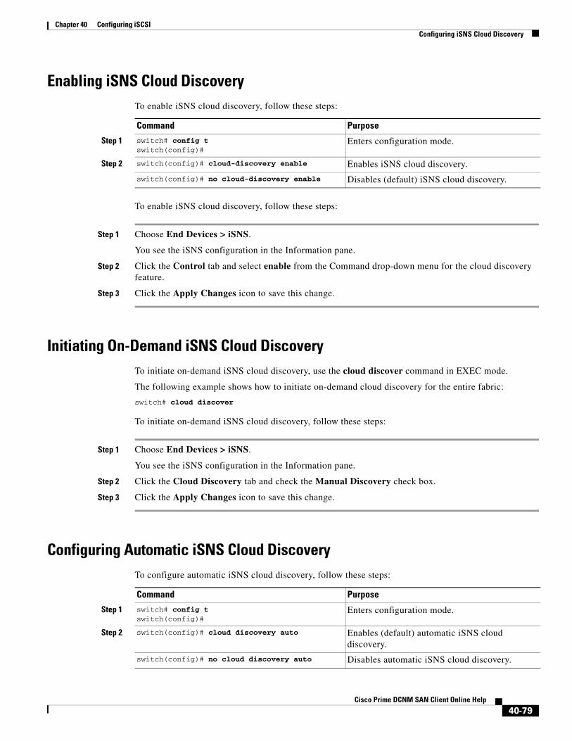
Chapter 40 Configuring iSCSIConfiguring iSNS Cloud Discovery
Enabling iSNS Cloud DiscoveryTo enable iSNS cloud discovery, follow these steps:
To enable iSNS cloud discovery, follow these steps:
Step 1 Choose End Devices > iSNS.
You see the iSNS configuration in the Information pane.
Step 2 Click the Control tab and select enable from the Command drop-down menu for the cloud discovery feature.
Step 3 Click the Apply Changes icon to save this change.
Initiating On-Demand iSNS Cloud DiscoveryTo initiate on-demand iSNS cloud discovery, use the cloud discover command in EXEC mode.
The following example shows how to initiate on-demand cloud discovery for the entire fabric:
switch# cloud discover
To initiate on-demand iSNS cloud discovery, follow these steps:
Step 1 Choose End Devices > iSNS.
You see the iSNS configuration in the Information pane.
Step 2 Click the Cloud Discovery tab and check the Manual Discovery check box.
Step 3 Click the Apply Changes icon to save this change.
Configuring Automatic iSNS Cloud DiscoveryTo configure automatic iSNS cloud discovery, follow these steps:
Command Purpose
Step 1 switch# config tswitch(config)#
Enters configuration mode.
Step 2 switch(config)# cloud-discovery enable Enables iSNS cloud discovery.
switch(config)# no cloud-discovery enable Disables (default) iSNS cloud discovery.
Command Purpose
Step 1 switch# config tswitch(config)#
Enters configuration mode.
Step 2 switch(config)# cloud discovery auto Enables (default) automatic iSNS cloud discovery.
switch(config)# no cloud discovery auto Disables automatic iSNS cloud discovery.
40-79Cisco Prime DCNM SAN Client Online Help

Chapter 40 Configuring iSCSIConfiguring iSNS Cloud Discovery
To configure automatic iSNS cloud discovery, follow these steps:
Step 1 Choose End Devices > iSNS.
You see the iSNS configuration in the Information pane.
Step 2 Click the Cloud Discovery tab and check the AutoDiscovery check box.
Step 3 Click the Apply Changes icon to save this change.
Configuring iSNS Cloud Discovery Distribution
Detailed Steps
To configure iSNS cloud discovery distribution using CFS, follow these steps:
To configure iSNS cloud discovery CFS distribution, follow these steps:
Step 1 Choose End Devices > iSNS.
You see the iSNS configuration in the Information pane.
Step 2 Click the CFS tab and select enable from the Admin drop-down menu for the cloud discovery feature.
Step 3 Select enable from the Global drop-down menu for the cloud discovery feature.
Step 4 Click the Apply Changes icon to save this change.
Configuring iSNS Cloud Discovery Message TypesYou can configure iSNS cloud discovery the type of message to use. By default, iSNS cloud discovery uses ICMP.
To configure iSNS cloud discovery message types, follow these steps:
Command Purpose
Step 1 switch# config tswitch(config)#
Enters configuration mode.
Step 2 switch(config)# cloud discovery fabric distribute
Enables (default) iSNS cloud discovery fabric distribution.
switch(config)# no cloud discovery fabric distribute
Disables iSNS cloud discovery fabric distribution.
Command Purpose
Step 1 switch# config tswitch(config)#
Enters configuration mode.
Step 2 switch(config)# cloud discovery message icmp
Enables (default) iSNS cloud discovery using ICMP messages.
Note Only ICMP messages are supported.
40-80Cisco Prime DCNM SAN Client Online Help

Chapter 40 Configuring iSCSIVerifying iSCSI Configuration
Verifying iSCSI ConfigurationTo display iSCSI configuration information, perform one of the following tasks:
Command Purpose
show interface iscsi 4/1 Displays the iSCSI Interface Information
show iscsi stats iscsi 2/1 Display brief iSCSI statistics for an iSCSI interface.
show iscsi stats iscsi 2/1 detail Displays detailed iSCSI statistics for the iSCSI interface.
show interface iscsi 4/1 Displays proxy initiator information for the iSCSI interface with system-assigned WWNs.
show interface iscsi 4/2 Displays proxy initiator information for the iSCSI interface with user-assigned WWNs.
show iscsi global Displays the current global iSCSI configuration and date.
show iscsi session. Displays brief information of all iSCSI sessions.
show iscsi session initiator 10.10.100.199 target VT1
Displays brief information about the specified iSCSI ession.
show iscsi session initiator 10.10.100.199 target VT1 detail
Displays detailed information about the specified iSCSI session.
switch# show iscsi initiator Displays information about connected iSCSI initiators.
show iscsi initiator iqn.1987-05.com.cisco:02.3021b0f2fda0.avanti12-w2k detail
Displays detailed information about the iSCSI initiator.
show fcns database Displays the FCNS database contents.
show fcns database detail. Displays the FCNS database in detail.
show iscsi initiator configured Displays information about configured initiators.
show iscsi virtual-target Displays exported targets.
show user-account iscsi Displays iSCSI user names.
show islb initiator configured Verifies the iSLB initiator configuration.
show islb initiator configured Verifies the iSLB target configuration.
show zoneset active Shows the show zoneset active command output when the dynamically generated zone name is used.
show zoneset active Shows the show zoneset active command output when the configured zone name IslbZone is used.
show islb initiator configured Verifies the iSLB user name and mutual CHAP configuration.
show vrrp vr 1 Verifies the iSLB VRRP load balancing configuration for IPv4.
show vrrp ipv6 vr 1 Verifies the iSLB VRRP load balancing configuration for IPv6.
40-81Cisco Prime DCNM SAN Client Online Help

Chapter 40 Configuring iSCSIVerifying iSCSI Configuration
show islb vrrp summary vr 30 Displays VRRP load balancing information.
show islb pending Displays the pending configuration changes.
show islb pending-diff Displays the differences between the pending configuration and the current configuration.
show islb status Displays the iSLB CFS status.
show islb cfs-session status Displays the status of the iSLB CFS distribution session.
show islb merge status Displays the iSLB CFS merge status.
show isns profile Displays information for configured iSNS profiles.
show isns profile ABC Displays a specified iSNS profile.
show isns profile counters Displays configured profiles with iSNS statistics.
show isns profile ABC counters Displays iSNS statistics for a specified profile.
show isns query ABC gigabitethernet 2/3 Displays iSNS queries.
show interface gigabitethernet 2/3 Displays tagged iSNS interfaces.
show isns config Displays the iSNS server configuration of ESI interval and database contents.
show isns database Displays explicitly registered objects.
show isns database full Displays the full database with both registered and configured nodes and portal.
show isns database virtual-targets local Displays the virtual target information in the local switch.
show isns database virtual-targets switch 20:00:00:0d:ec:01:04:40
Displays virtual target for a specified switch.
show isns node all Displays explicitly registered objects.
show isns node name iqn.com.cisco.disk1 Displays the specified node.
show isns node all detail Displays the attribute details for all nodes.
show isns portal all Displays the attribute information for all portals.
show isns portal all detail Displays detailed attribute information for all portals.
show isns portal virtual Displays virtual portals.
show isns portal virtual switch 20:00:00:0d:ec:01:04:40
Displays virtual portals for the specified switch.
show isns portal virtual switch 20:00:00:0d:ec:01:04:40 detail
Displays detailed information for the virtual portals in the specified switch.
show isns entity Displays all registered entries.
show isns entity all Displays all entities in the database.
show isns entity id dp-204 Displays the entity with the specified ID.
show isns entity all detail Displays detailed information for all entities in the database.
Command Purpose
40-82Cisco Prime DCNM SAN Client Online Help
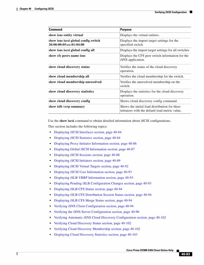
Chapter 40 Configuring iSCSIVerifying iSCSI Configuration
Use the show iscsi command to obtain detailed information about iSCSI configurations.
This section includes the following topics:
• Displaying iSCSI Interfaces section, page 40-84
• Displaying iSCSI Statistics section, page 40-84
• Displaying Proxy Initiator Information section, page 40-86
• Displaying Global iSCSI Information section, page 40-87
• Displaying iSCSI Sessions section, page 40-88
• Displaying iSCSI Initiators section, page 40-89
• Displaying iSCSI Virtual Targets section, page 40-92
• Displaying iSCSI User Information section, page 40-93
• Displaying iSLB VRRP Information section, page 40-93
• Displaying Pending iSLB Configuration Changes section, page 40-93
• Displaying iSLB CFS Status section, page 40-94
• Displaying iSLB CFS Distribution Session Status section, page 40-94
• Displaying iSLB CFS Merge Status section, page 40-94
• Verifying iSNS Client Configuration section, page 40-94
• Verifying the iSNS Server Configuration section, page 40-96
• Verifying Automatic iSNS Cloud Discovery Configuration section, page 40-102
• Verifying Cloud Discovery Status section, page 40-102
• Verifying Cloud Discovery Membership section, page 40-102
• Displaying Cloud Discovery Statistics section, page 40-103
show isns entity virtual Displays the virtual entities.
show isns iscsi global config switch 20:00:00:05:ec:01:04:00
Displays the import target settings for the specified switch.
show isns iscsi global config all Displays the import target settings for all switches
show cfs peers name isns Displays the CFS peer switch information for the iSNS application.
show cloud discovery status Verifies the status of the cloud discovery operation.
show cloud membership all Verifies the cloud membership for the switch.
show cloud membership unresolved Verifies the unresolved membership on the switch.
show cloud discovery statistics Displays the statistics for the cloud discovery operation.
show cloud discovery config Shows cloud discovery config command.
show islb vrrp summary Shows the initial load distribution for three initiators with the default load metric value.
Command Purpose
40-83Cisco Prime DCNM SAN Client Online Help
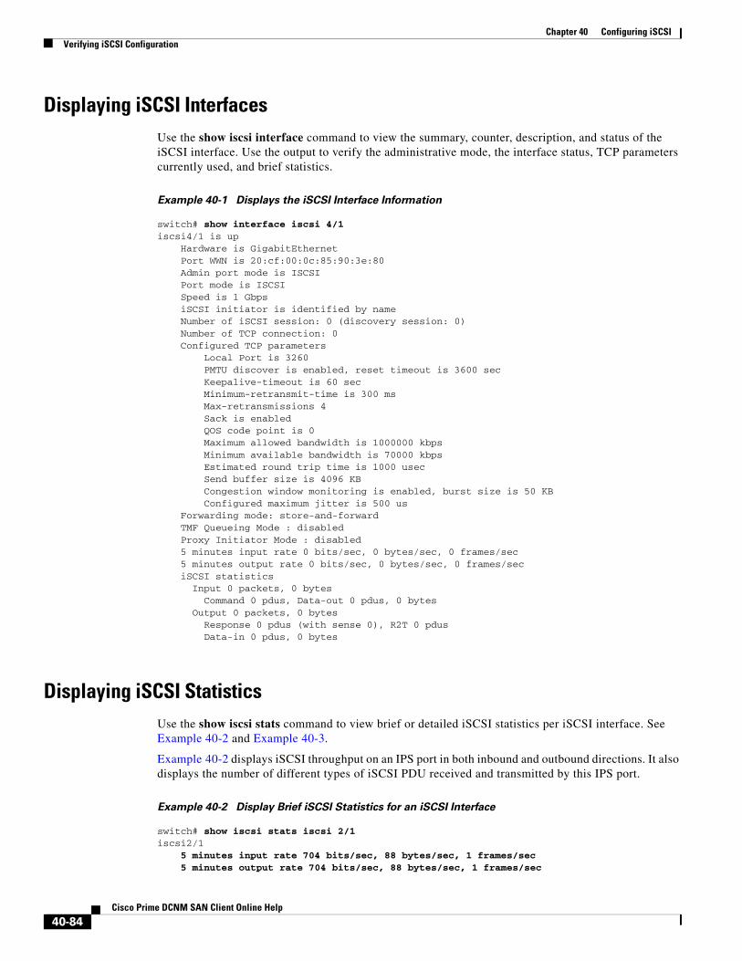
Chapter 40 Configuring iSCSIVerifying iSCSI Configuration
Displaying iSCSI InterfacesUse the show iscsi interface command to view the summary, counter, description, and status of the iSCSI interface. Use the output to verify the administrative mode, the interface status, TCP parameters currently used, and brief statistics.
Example 40-1 Displays the iSCSI Interface Information
switch# show interface iscsi 4/1iscsi4/1 is up Hardware is GigabitEthernet Port WWN is 20:cf:00:0c:85:90:3e:80 Admin port mode is ISCSI Port mode is ISCSI Speed is 1 Gbps iSCSI initiator is identified by name Number of iSCSI session: 0 (discovery session: 0) Number of TCP connection: 0 Configured TCP parameters Local Port is 3260 PMTU discover is enabled, reset timeout is 3600 sec Keepalive-timeout is 60 sec Minimum-retransmit-time is 300 ms Max-retransmissions 4 Sack is enabled QOS code point is 0 Maximum allowed bandwidth is 1000000 kbps Minimum available bandwidth is 70000 kbps Estimated round trip time is 1000 usec Send buffer size is 4096 KB Congestion window monitoring is enabled, burst size is 50 KB Configured maximum jitter is 500 us Forwarding mode: store-and-forward TMF Queueing Mode : disabled Proxy Initiator Mode : disabled 5 minutes input rate 0 bits/sec, 0 bytes/sec, 0 frames/sec 5 minutes output rate 0 bits/sec, 0 bytes/sec, 0 frames/sec iSCSI statistics Input 0 packets, 0 bytes Command 0 pdus, Data-out 0 pdus, 0 bytes Output 0 packets, 0 bytes Response 0 pdus (with sense 0), R2T 0 pdus Data-in 0 pdus, 0 bytes
Displaying iSCSI StatisticsUse the show iscsi stats command to view brief or detailed iSCSI statistics per iSCSI interface. See Example 40-2 and Example 40-3.
Example 40-2 displays iSCSI throughput on an IPS port in both inbound and outbound directions. It also displays the number of different types of iSCSI PDU received and transmitted by this IPS port.
Example 40-2 Display Brief iSCSI Statistics for an iSCSI Interface
switch# show iscsi stats iscsi 2/1iscsi2/1 5 minutes input rate 704 bits/sec, 88 bytes/sec, 1 frames/sec 5 minutes output rate 704 bits/sec, 88 bytes/sec, 1 frames/sec
40-84Cisco Prime DCNM SAN Client Online Help
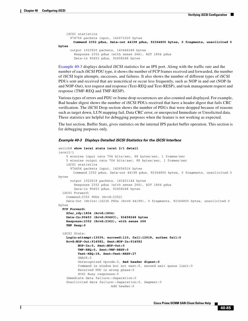
Chapter 40 Configuring iSCSIVerifying iSCSI Configuration
iSCSI statistics 974756 packets input, 142671620 bytes Command 2352 pdus, Data-out 44198 pdus, 92364800 bytes, 0 fragments, unsolicited 0 bytes output 1022920 packets, 143446248 bytes Response 2352 pdus (with sense 266), R2T 1804 pdus Data-in 90453 pdus, 92458248 bytes
Example 40-3 displays detailed iSCSI statistics for an IPS port. Along with the traffic rate and the number of each iSCSI PDU type, it shows the number of FCP frames received and forwarded, the number of iSCSI login attempts, successes, and failures. It also shows the number of different types of iSCSI PDUs sent and received that are noncritical or occur less frequently, such as NOP in and out (NOP-In and NOP-Out), text request and response (Text-REQ and Text-RESP), and task management request and response (TMF-REQ and TMF-RESP).
Various types of errors and PDU or frame drop occurrences are also counted and displayed. For example, Bad header digest shows the number of iSCSI PDUs received that have a header digest that fails CRC verification. The iSCSI Drop section shows the number of PDUs that were dropped because of reasons such as target down, LUN mapping fail, Data CRC error, or unexpected Immediate or Unsolicited data. These statistics are helpful for debugging purposes when the feature is not working as expected.
The last section, Buffer Stats, gives statistics on the internal IPS packet buffer operation. This section is for debugging purposes only.
Example 40-3 Displays Detailed iSCSI Statistics for the iSCSI Interface
switch# show iscsi stats iscsi 2/1 detail iscsi2/1 5 minutes input rate 704 bits/sec, 88 bytes/sec, 1 frames/sec 5 minutes output rate 704 bits/sec, 88 bytes/sec, 1 frames/sec iSCSI statistics 974454 packets input, 142656516 bytes Command 2352 pdus, Data-out 44198 pdus, 92364800 bytes, 0 fragments, unsolicited 0 bytes output 1022618 packets, 143431144 bytes Response 2352 pdus (with sense 266), R2T 1804 pdus Data-in 90453 pdus, 92458248 bytes iSCSI Forward: Command:2352 PDUs (Rcvd:2352) Data-Out (Write):16236 PDUs (Rcvd 44198), 0 fragments, 92364800 bytes, unsolicited 0 bytes FCP Forward: Xfer_rdy:1804 (Rcvd:1804) Data-In:90453 (Rcvd:90463), 92458248 bytes Response:2352 (Rcvd:2362), with sense 266 TMF Resp:0
iSCSI Stats: Login:attempt:13039, succeed:110, fail:12918, authen fail:0 Rcvd:NOP-Out:914582, Sent:NOP-In:914582 NOP-In:0, Sent:NOP-Out:0 TMF-REQ:0, Sent:TMF-RESP:0 Text-REQ:18, Sent:Text-RESP:27 SNACK:0 Unrecognized Opcode:0, Bad header digest:0 Command in window but not next:0, exceed wait queue limit:0 Received PDU in wrong phase:0 SCSI Busy responses:0 Immediate data failure::Separation:0 Unsolicited data failure::Separation:0, Segment:0 Add header:0
40-85Cisco Prime DCNM SAN Client Online Help
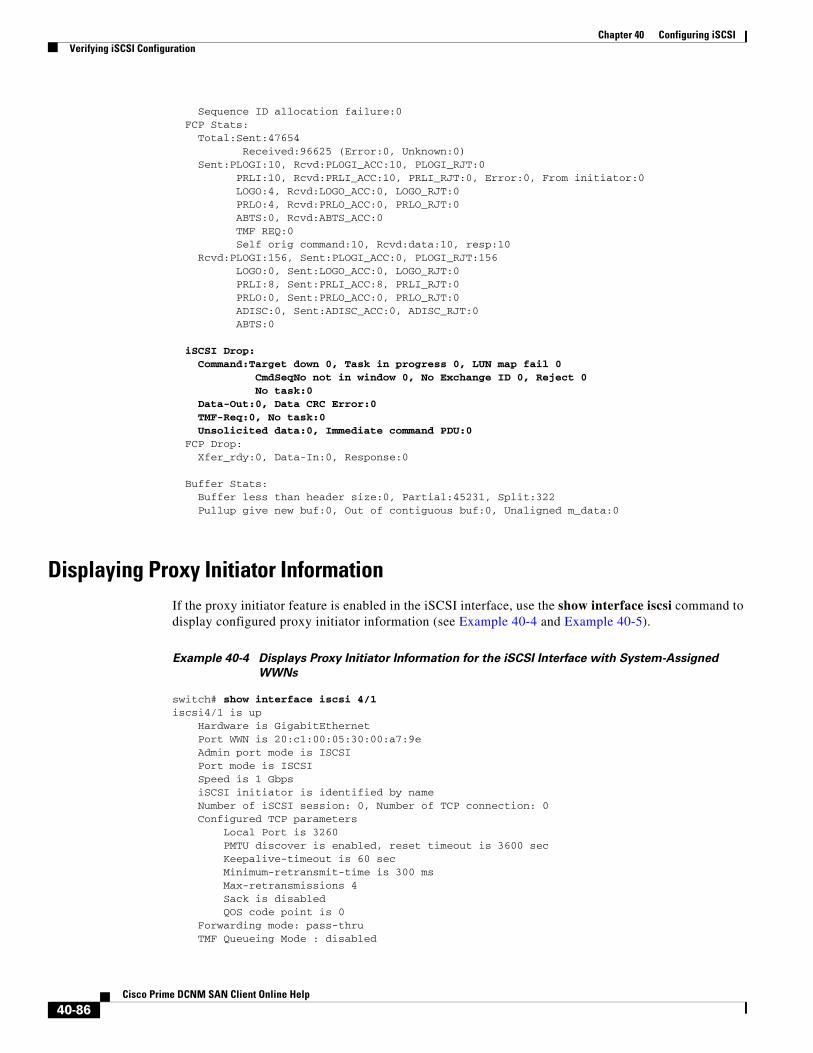
Chapter 40 Configuring iSCSIVerifying iSCSI Configuration
Sequence ID allocation failure:0 FCP Stats: Total:Sent:47654 Received:96625 (Error:0, Unknown:0) Sent:PLOGI:10, Rcvd:PLOGI_ACC:10, PLOGI_RJT:0 PRLI:10, Rcvd:PRLI_ACC:10, PRLI_RJT:0, Error:0, From initiator:0 LOGO:4, Rcvd:LOGO_ACC:0, LOGO_RJT:0 PRLO:4, Rcvd:PRLO_ACC:0, PRLO_RJT:0 ABTS:0, Rcvd:ABTS_ACC:0 TMF REQ:0 Self orig command:10, Rcvd:data:10, resp:10 Rcvd:PLOGI:156, Sent:PLOGI_ACC:0, PLOGI_RJT:156 LOGO:0, Sent:LOGO_ACC:0, LOGO_RJT:0 PRLI:8, Sent:PRLI_ACC:8, PRLI_RJT:0 PRLO:0, Sent:PRLO_ACC:0, PRLO_RJT:0 ADISC:0, Sent:ADISC_ACC:0, ADISC_RJT:0 ABTS:0
iSCSI Drop: Command:Target down 0, Task in progress 0, LUN map fail 0 CmdSeqNo not in window 0, No Exchange ID 0, Reject 0 No task:0 Data-Out:0, Data CRC Error:0 TMF-Req:0, No task:0 Unsolicited data:0, Immediate command PDU:0 FCP Drop: Xfer_rdy:0, Data-In:0, Response:0
Buffer Stats: Buffer less than header size:0, Partial:45231, Split:322 Pullup give new buf:0, Out of contiguous buf:0, Unaligned m_data:0
Displaying Proxy Initiator InformationIf the proxy initiator feature is enabled in the iSCSI interface, use the show interface iscsi command to display configured proxy initiator information (see Example 40-4 and Example 40-5).
Example 40-4 Displays Proxy Initiator Information for the iSCSI Interface with System-Assigned
WWNs
switch# show interface iscsi 4/1 iscsi4/1 is up Hardware is GigabitEthernet Port WWN is 20:c1:00:05:30:00:a7:9e Admin port mode is ISCSI Port mode is ISCSI Speed is 1 Gbps iSCSI initiator is identified by name Number of iSCSI session: 0, Number of TCP connection: 0 Configured TCP parameters Local Port is 3260 PMTU discover is enabled, reset timeout is 3600 sec Keepalive-timeout is 60 sec Minimum-retransmit-time is 300 ms Max-retransmissions 4 Sack is disabled QOS code point is 0 Forwarding mode: pass-thru TMF Queueing Mode : disabled
40-86Cisco Prime DCNM SAN Client Online Help
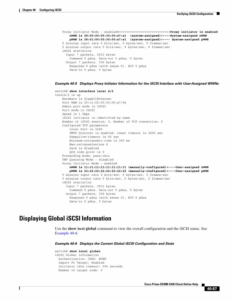
Chapter 40 Configuring iSCSIVerifying iSCSI Configuration
Proxy Initiator Mode : enabled<----------------------------Proxy initiator is enabled nWWN is 28:00:00:05:30:00:a7:a1 (system-assigned)<----System-assigned nWWN pWWN is 28:01:00:05:30:00:a7:a1 (system-assigned)<---- System-assigned pWWN 5 minutes input rate 0 bits/sec, 0 bytes/sec, 0 frames/sec 5 minutes output rate 0 bits/sec, 0 bytes/sec, 0 frames/sec iSCSI statistics Input 7 packets, 2912 bytes Command 0 pdus, Data-out 0 pdus, 0 bytes Output 7 packets, 336 bytes Response 0 pdus (with sense 0), R2T 0 pdus Data-in 0 pdus, 0 bytes
Example 40-5 Displays Proxy Initiator Information for the iSCSI Interface with User-Assigned WWNs
switch# show interface iscsi 4/2 iscsi4/2 is up Hardware is GigabitEthernet Port WWN is 20:c1:00:05:30:00:a7:9e Admin port mode is ISCSI Port mode is ISCSI Speed is 1 Gbps iSCSI initiator is identified by name Number of iSCSI session: 0, Number of TCP connection: 0 Configured TCP parameters Local Port is 3260 PMTU discover is enabled, reset timeout is 3600 sec Keepalive-timeout is 60 sec Minimum-retransmit-time is 300 ms Max-retransmissions 4 Sack is disabled QOS code point is 0 Forwarding mode: pass-thru TMF Queueing Mode : disabled Proxy Initiator Mode : enabled nWWN is 11:11:11:11:11:11:11:11 (manually-configured)<----User-assigned nWWN pWWN is 22:22:22:22:22:22:22:22 (manually-configured)<----User-assigned pWWN 5 minutes input rate 0 bits/sec, 0 bytes/sec, 0 frames/sec 5 minutes output rate 0 bits/sec, 0 bytes/sec, 0 frames/sec iSCSI statistics Input 7 packets, 2912 bytes Command 0 pdus, Data-out 0 pdus, 0 bytes Output 7 packets, 336 bytes Response 0 pdus (with sense 0), R2T 0 pdus Data-in 0 pdus, 0 bytes
Displaying Global iSCSI InformationUse the show iscsi global command to view the overall configuration and the iSCSI status. See Example 40-6.
Example 40-6 Displays the Current Global iSCSI Configuration and State
switch# show iscsi globaliSCSI Global information Authentication: CHAP, NONE Import FC Target: Enabled Initiator idle timeout: 300 seconds Number of target node: 0
40-87Cisco Prime DCNM SAN Client Online Help
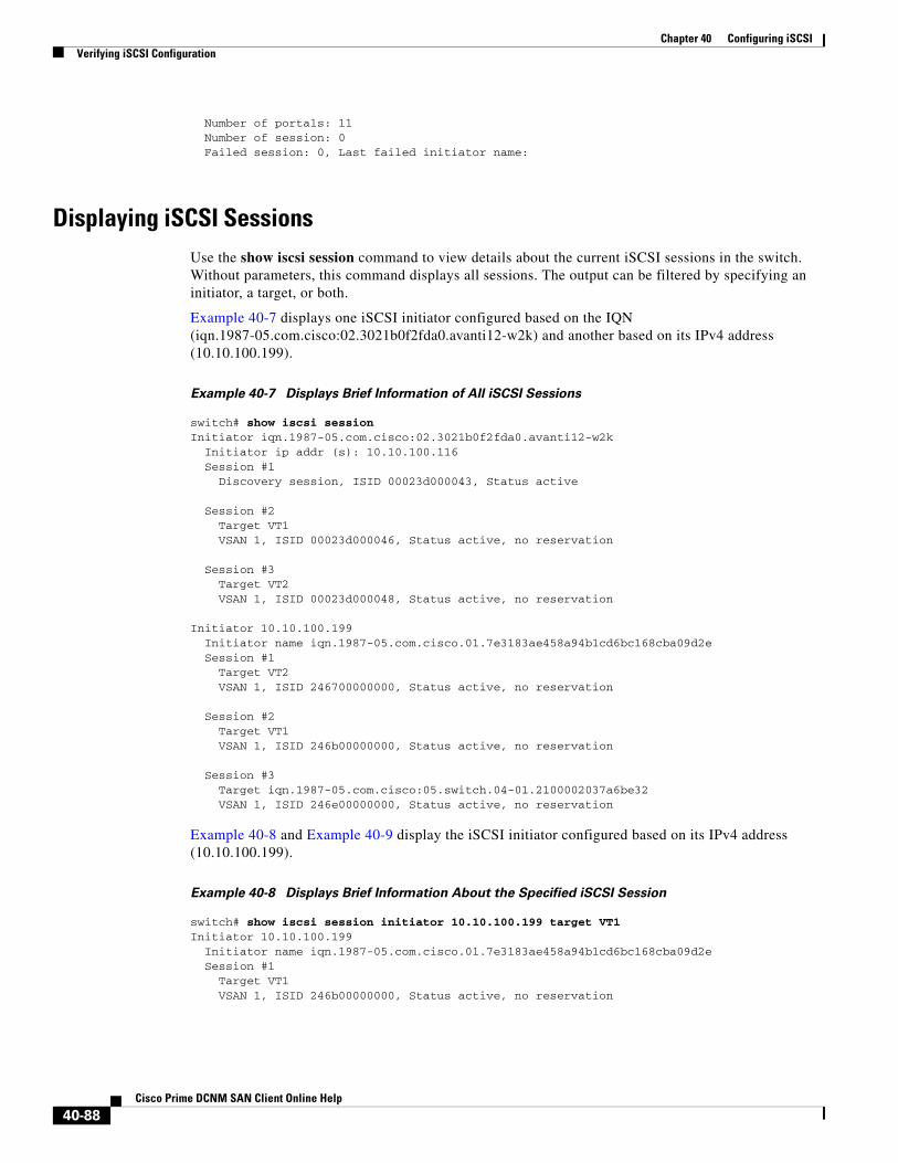
Chapter 40 Configuring iSCSIVerifying iSCSI Configuration
Number of portals: 11 Number of session: 0 Failed session: 0, Last failed initiator name:
Displaying iSCSI SessionsUse the show iscsi session command to view details about the current iSCSI sessions in the switch. Without parameters, this command displays all sessions. The output can be filtered by specifying an initiator, a target, or both.
Example 40-7 displays one iSCSI initiator configured based on the IQN (iqn.1987-05.com.cisco:02.3021b0f2fda0.avanti12-w2k) and another based on its IPv4 address (10.10.100.199).
Example 40-7 Displays Brief Information of All iSCSI Sessions
switch# show iscsi session Initiator iqn.1987-05.com.cisco:02.3021b0f2fda0.avanti12-w2k
Initiator ip addr (s): 10.10.100.116 Session #1 Discovery session, ISID 00023d000043, Status active
Session #2 Target VT1 VSAN 1, ISID 00023d000046, Status active, no reservation
Session #3 Target VT2 VSAN 1, ISID 00023d000048, Status active, no reservation
Initiator 10.10.100.199 Initiator name iqn.1987-05.com.cisco.01.7e3183ae458a94b1cd6bc168cba09d2e Session #1 Target VT2 VSAN 1, ISID 246700000000, Status active, no reservation
Session #2 Target VT1 VSAN 1, ISID 246b00000000, Status active, no reservation
Session #3 Target iqn.1987-05.com.cisco:05.switch.04-01.2100002037a6be32 VSAN 1, ISID 246e00000000, Status active, no reservation
Example 40-8 and Example 40-9 display the iSCSI initiator configured based on its IPv4 address (10.10.100.199).
Example 40-8 Displays Brief Information About the Specified iSCSI Session
switch# show iscsi session initiator 10.10.100.199 target VT1Initiator 10.10.100.199 Initiator name iqn.1987-05.com.cisco.01.7e3183ae458a94b1cd6bc168cba09d2e Session #1 Target VT1 VSAN 1, ISID 246b00000000, Status active, no reservation
40-88Cisco Prime DCNM SAN Client Online Help
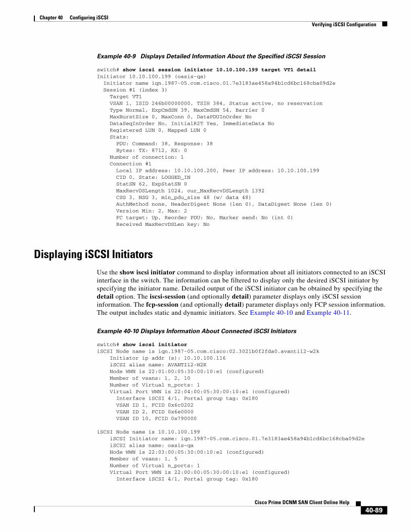
Chapter 40 Configuring iSCSIVerifying iSCSI Configuration
Example 40-9 Displays Detailed Information About the Specified iSCSI Session
switch# show iscsi session initiator 10.10.100.199 target VT1 detailInitiator 10.10.100.199 (oasis-qa) Initiator name iqn.1987-05.com.cisco.01.7e3183ae458a94b1cd6bc168cba09d2e Session #1 (index 3) Target VT1 VSAN 1, ISID 246b00000000, TSIH 384, Status active, no reservation Type Normal, ExpCmdSN 39, MaxCmdSN 54, Barrier 0 MaxBurstSize 0, MaxConn 0, DataPDUInOrder No DataSeqInOrder No, InitialR2T Yes, ImmediateData No Registered LUN 0, Mapped LUN 0 Stats: PDU: Command: 38, Response: 38 Bytes: TX: 8712, RX: 0 Number of connection: 1 Connection #1 Local IP address: 10.10.100.200, Peer IP address: 10.10.100.199 CID 0, State: LOGGED_IN StatSN 62, ExpStatSN 0 MaxRecvDSLength 1024, our_MaxRecvDSLength 1392 CSG 3, NSG 3, min_pdu_size 48 (w/ data 48) AuthMethod none, HeaderDigest None (len 0), DataDigest None (len 0) Version Min: 2, Max: 2 FC target: Up, Reorder PDU: No, Marker send: No (int 0) Received MaxRecvDSLen key: No
Displaying iSCSI InitiatorsUse the show iscsi initiator command to display information about all initiators connected to an iSCSI interface in the switch. The information can be filtered to display only the desired iSCSI initiator by specifying the initiator name. Detailed output of the iSCSI initiator can be obtained by specifying the detail option. The iscsi-session (and optionally detail) parameter displays only iSCSI session information. The fcp-session (and optionally detail) parameter displays only FCP session information. The output includes static and dynamic initiators. See Example 40-10 and Example 40-11.
Example 40-10 Displays Information About Connected iSCSI Initiators
switch# show iscsi initiatoriSCSI Node name is iqn.1987-05.com.cisco:02.3021b0f2fda0.avanti12-w2k Initiator ip addr (s): 10.10.100.116 iSCSI alias name: AVANTI12-W2K Node WWN is 22:01:00:05:30:00:10:e1 (configured) Member of vsans: 1, 2, 10 Number of Virtual n_ports: 1 Virtual Port WWN is 22:04:00:05:30:00:10:e1 (configured) Interface iSCSI 4/1, Portal group tag: 0x180 VSAN ID 1, FCID 0x6c0202 VSAN ID 2, FCID 0x6e0000 VSAN ID 10, FCID 0x790000
iSCSI Node name is 10.10.100.199 iSCSI Initiator name: iqn.1987-05.com.cisco.01.7e3183ae458a94b1cd6bc168cba09d2e iSCSI alias name: oasis-qa Node WWN is 22:03:00:05:30:00:10:e1 (configured) Member of vsans: 1, 5 Number of Virtual n_ports: 1 Virtual Port WWN is 22:00:00:05:30:00:10:e1 (configured) Interface iSCSI 4/1, Portal group tag: 0x180
40-89Cisco Prime DCNM SAN Client Online Help

Chapter 40 Configuring iSCSIVerifying iSCSI Configuration
VSAN ID 5, FCID 0x640000 VSAN ID 1, FCID 0x6c0203
Example 40-11 Displays Detailed Information About the iSCSI Initiator
switch# show iscsi initiator iqn.1987-05.com.cisco:02.3021b0f2fda0.avanti12-w2k detailiSCSI Node name is iqn.1987-05.com.cisco:02.3021b0f2fda0.avanti12-w2k Initiator ip addr (s): 10.10.100.116 iSCSI alias name: AVANTI12-W2K Node WWN is 22:01:00:05:30:00:10:e1 (configured) Member of vsans: 1, 2, 10 Number of Virtual n_ports: 1
Virtual Port WWN is 22:04:00:05:30:00:10:e1 (configured) Interface iSCSI 4/1, Portal group tag is 0x180 VSAN ID 1, FCID 0x6c0202 1 FC sessions, 1 iSCSI sessions iSCSI session details <-------------------iSCSI session details Target: VT1 Statistics: PDU: Command: 0, Response: 0 Bytes: TX: 0, RX: 0 Number of connection: 1 TCP parameters Local 10.10.100.200:3260, Remote 10.10.100.116:4190 Path MTU: 1500 bytes Retransmission timeout: 310 ms Round trip time: Smoothed 160 ms, Variance: 38 Advertized window: Current: 61 KB, Maximum: 62 KB, Scale: 0 Peer receive window: Current: 63 KB, Maximum: 63 KB, Scale: 0 Congestion window: Current: 1 KB
FCP Session details <-------------------FCP session details Target FCID: 0x6c01e8 (S_ID of this session: 0x6c0202) pWWN: 21:00:00:20:37:62:c0:0c, nWWN: 20:00:00:20:37:62:c0:0c Session state: CLEANUP 1 iSCSI sessions share this FC session Target: VT1 Negotiated parameters RcvDataFieldSize 1392 our_RcvDataFieldSize 1392 MaxBurstSize 0, EMPD: FALSE Random Relative Offset: FALSE, Sequence-in-order: Yes Statistics: PDU: Command: 0, Response: 0
Use the show fcns database (and optionally detail) to display the Fibre Channel name server entry for the Fibre Channel N port created for iSCSI initiators in the SAN. See Example 40-12 and Example 40-13.
Example 40-12 Displays the FCNS Database Contents
switch# show fcns databaseVSAN 1:--------------------------------------------------------------------------FCID TYPE PWWN (VENDOR) FC4-TYPE:FEATURE--------------------------------------------------------------------------0x020101 N 22:04:00:05:30:00:35:e1 (Cisco) scsi-fcp:init isc..w <--iSCSI 0x020102 N 22:02:00:05:30:00:35:e1 (Cisco) scsi-fcp:init isc..w initiator0x0205d4 NL 21:00:00:04:cf:da:fe:c6 (Seagate) scsi-fcp:target 0x0205d5 NL 21:00:00:04:cf:e6:e4:4b (Seagate) scsi-fcp:target ...
40-90Cisco Prime DCNM SAN Client Online Help

Chapter 40 Configuring iSCSIVerifying iSCSI Configuration
Total number of entries = 10
VSAN 2:--------------------------------------------------------------------------FCID TYPE PWWN (VENDOR) FC4-TYPE:FEATURE--------------------------------------------------------------------------0xef0001 N 22:02:00:05:30:00:35:e1 (Cisco) scsi-fcp:init isc..w Total number of entries = 1
VSAN 3:--------------------------------------------------------------------------FCID TYPE PWWN (VENDOR) FC4-TYPE:FEATURE--------------------------------------------------------------------------0xed0001 N 22:02:00:05:30:00:35:e1 (Cisco) scsi-fcp:init isc..w Total number of entries = 1
Example 40-13 Displays the FCNS Database in Detail
switch# show fcns database detail------------------------VSAN:1 FCID:0x020101------------------------port-wwn (vendor) :22:04:00:05:30:00:35:e1 (Cisco) node-wwn :22:03:00:05:30:00:35:e1class :2,3node-ip-addr :10.2.2.12 <--- iSCSI initiator's IPv4 addressipa :ff ff ff ff ff ff ff fffc4-types:fc4_features:scsi-fcp:init iscsi-gw symbolic-port-name :symbolic-node-name :iqn.1991-05.com.microsoft:oasis2-dell <--- iSCSI initiator's IQNport-type :N port-ip-addr :0.0.0.0fabric-port-wwn :22:01:00:05:30:00:35:dehard-addr :0x000000------------------------VSAN:1 FCID:0x020102------------------------port-wwn (vendor) :22:02:00:05:30:00:35:e1 (Cisco) node-wwn :22:01:00:05:30:00:35:e1class :2,3node-ip-addr :10.2.2.11ipa :ff ff ff ff ff ff ff fffc4-types:fc4_features:scsi-fcp:init iscsi-gw symbolic-port-name :symbolic-node-name :iqn.1987-05.com.cisco.01.14ac33ba567f986f174723b5f9f2377port-type :N port-ip-addr :0.0.0.0fabric-port-wwn :22:01:00:05:30:00:35:dehard-addr :0x000000...Total number of entries = 10======================================================================------------------------VSAN:2 FCID:0xef0001------------------------port-wwn (vendor) :22:02:00:05:30:00:35:e1 (Cisco) node-wwn :22:01:00:05:30:00:35:e1class :2,3node-ip-addr :10.2.2.11ipa :ff ff ff ff ff ff ff fffc4-types:fc4_features:scsi-fcp:init iscsi-gw symbolic-port-name :
40-91Cisco Prime DCNM SAN Client Online Help
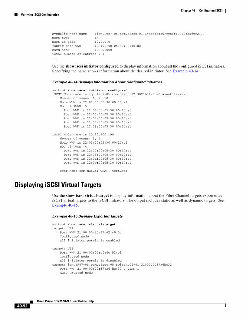
Chapter 40 Configuring iSCSIVerifying iSCSI Configuration
symbolic-node-name :iqn.1987-05.com.cisco.01.14ac33ba567f986f174723b5f9f2377port-type :N port-ip-addr :0.0.0.0fabric-port-wwn :22:01:00:05:30:00:35:dehard-addr :0x000000Total number of entries = 1...
Use the show iscsi initiator configured to display information about all the configured iSCSI initiators. Specifying the name shows information about the desired initiator. See Example 40-14.
Example 40-14 Displays Information About Configured Initiators
switch# show iscsi initiator configurediSCSI Node name is iqn.1987-05.com.cisco:02.3021b0f2fda0.avanti12-w2k Member of vsans: 1, 2, 10 Node WWN is 22:01:00:05:30:00:10:e1 No. of PWWN: 5 Port WWN is 22:04:00:05:30:00:10:e1 Port WWN is 22:05:00:05:30:00:10:e1 Port WWN is 22:06:00:05:30:00:10:e1 Port WWN is 22:07:00:05:30:00:10:e1 Port WWN is 22:08:00:05:30:00:10:e1
iSCSI Node name is 10.10.100.199 Member of vsans: 1, 5 Node WWN is 22:03:00:05:30:00:10:e1 No. of PWWN: 4 Port WWN is 22:00:00:05:30:00:10:e1 Port WWN is 22:09:00:05:30:00:10:e1 Port WWN is 22:0a:00:05:30:00:10:e1 Port WWN is 22:0b:00:05:30:00:10:e1
User Name for Mutual CHAP: testuser
Displaying iSCSI Virtual TargetsUse the show iscsi virtual-target to display information about the Fibre Channel targets exported as iSCSI virtual targets to the iSCSI initiators. The output includes static as well as dynamic targets. See Example 40-15.
Example 40-15 Displays Exported Targets
switch# show iscsi virtual-targettarget: VT1 * Port WWN 21:00:00:20:37:62:c0:0c Configured node all initiator permit is enabled
target: VT2 Port WWN 21:00:00:04:cf:4c:52:c1 Configured node all initiator permit is disabledtarget: iqn.1987-05.com.cisco:05.switch.04-01.2100002037a6be32 Port WWN 21:00:00:20:37:a6:be:32 , VSAN 1 Auto-created node
40-92Cisco Prime DCNM SAN Client Online Help
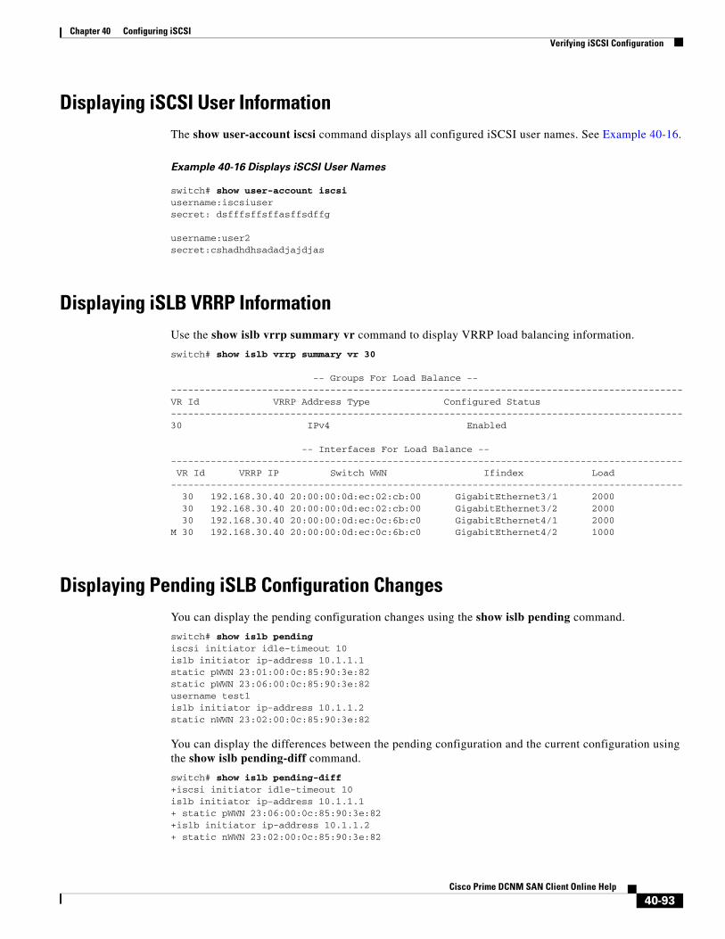
Chapter 40 Configuring iSCSIVerifying iSCSI Configuration
Displaying iSCSI User InformationThe show user-account iscsi command displays all configured iSCSI user names. See Example 40-16.
Example 40-16 Displays iSCSI User Names
switch# show user-account iscsi username:iscsiusersecret: dsfffsffsffasffsdffg
username:user2secret:cshadhdhsadadjajdjas
Displaying iSLB VRRP InformationUse the show islb vrrp summary vr command to display VRRP load balancing information.
switch# show islb vrrp summary vr 30
-- Groups For Load Balance --------------------------------------------------------------------------------------------VR Id VRRP Address Type Configured Status------------------------------------------------------------------------------------------30 IPv4 Enabled
-- Interfaces For Load Balance -------------------------------------------------------------------------------------------- VR Id VRRP IP Switch WWN Ifindex Load------------------------------------------------------------------------------------------ 30 192.168.30.40 20:00:00:0d:ec:02:cb:00 GigabitEthernet3/1 2000 30 192.168.30.40 20:00:00:0d:ec:02:cb:00 GigabitEthernet3/2 2000 30 192.168.30.40 20:00:00:0d:ec:0c:6b:c0 GigabitEthernet4/1 2000M 30 192.168.30.40 20:00:00:0d:ec:0c:6b:c0 GigabitEthernet4/2 1000
Displaying Pending iSLB Configuration ChangesYou can display the pending configuration changes using the show islb pending command.
switch# show islb pendingiscsi initiator idle-timeout 10islb initiator ip-address 10.1.1.1static pWWN 23:01:00:0c:85:90:3e:82static pWWN 23:06:00:0c:85:90:3e:82username test1islb initiator ip-address 10.1.1.2static nWWN 23:02:00:0c:85:90:3e:82
You can display the differences between the pending configuration and the current configuration using the show islb pending-diff command.
switch# show islb pending-diff+iscsi initiator idle-timeout 10islb initiator ip-address 10.1.1.1+ static pWWN 23:06:00:0c:85:90:3e:82+islb initiator ip-address 10.1.1.2+ static nWWN 23:02:00:0c:85:90:3e:82
40-93Cisco Prime DCNM SAN Client Online Help

Chapter 40 Configuring iSCSIVerifying iSCSI Configuration
Displaying iSLB CFS StatusYou can display the iSLB CFS status using the show islb session status command.
switch# show islb statusiSLB Distribute is enablediSLB CFS Session exists
Displaying iSLB CFS Distribution Session StatusYou can display the status of the iSLB CFS distribution session using the show islb cfs-session status command.
switch# show islb cfs-session statuslast action : fabric distribute enablelast action result : successlast action failure cause : success
Displaying iSLB CFS Merge StatusYou can display the iSLB CFS merge status using the show islb merge status command.
switch# show islb merge statusMerge Status: Success
Verifying iSNS Client ConfigurationUse the show isns profile command to view configured iSNS profiles. Profile ABC has two portals registered with the iSNS server. Each portal corresponds to a particular interface. Profile XYZ has a specified iSNS server, but does not have any tagged interfaces configured (see Example 40-17 and Example 40-18).
Example 40-17 Displays Information for Configured iSNS Profiles
switch# show isns profile iSNS profile name ABCtagged interface GigabitEthernet2/3tagged interface GigabitEthernet2/2iSNS Server 10.10.100.204
iSNS profile name XYZiSNS Server 10.10.100.211
Example 40-18 Displays a Specified iSNS Profile
switch# show isns profile ABCiSNS profile name ABCtagged interface GigabitEthernet2/3
40-94Cisco Prime DCNM SAN Client Online Help
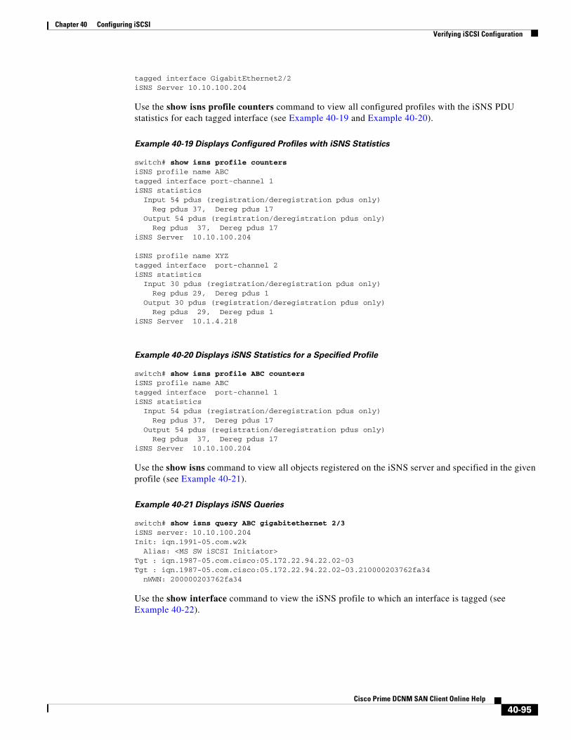
Chapter 40 Configuring iSCSIVerifying iSCSI Configuration
tagged interface GigabitEthernet2/2iSNS Server 10.10.100.204
Use the show isns profile counters command to view all configured profiles with the iSNS PDU statistics for each tagged interface (see Example 40-19 and Example 40-20).
Example 40-19 Displays Configured Profiles with iSNS Statistics
switch# show isns profile countersiSNS profile name ABCtagged interface port-channel 1iSNS statistics Input 54 pdus (registration/deregistration pdus only) Reg pdus 37, Dereg pdus 17 Output 54 pdus (registration/deregistration pdus only) Reg pdus 37, Dereg pdus 17iSNS Server 10.10.100.204
iSNS profile name XYZtagged interface port-channel 2iSNS statistics Input 30 pdus (registration/deregistration pdus only) Reg pdus 29, Dereg pdus 1 Output 30 pdus (registration/deregistration pdus only) Reg pdus 29, Dereg pdus 1iSNS Server 10.1.4.218
Example 40-20 Displays iSNS Statistics for a Specified Profile
switch# show isns profile ABC countersiSNS profile name ABCtagged interface port-channel 1iSNS statistics Input 54 pdus (registration/deregistration pdus only) Reg pdus 37, Dereg pdus 17 Output 54 pdus (registration/deregistration pdus only) Reg pdus 37, Dereg pdus 17iSNS Server 10.10.100.204
Use the show isns command to view all objects registered on the iSNS server and specified in the given profile (see Example 40-21).
Example 40-21 Displays iSNS Queries
switch# show isns query ABC gigabitethernet 2/3iSNS server: 10.10.100.204Init: iqn.1991-05.com.w2k Alias: <MS SW iSCSI Initiator>Tgt : iqn.1987-05.com.cisco:05.172.22.94.22.02-03Tgt : iqn.1987-05.com.cisco:05.172.22.94.22.02-03.210000203762fa34 nWWN: 200000203762fa34
Use the show interface command to view the iSNS profile to which an interface is tagged (see Example 40-22).
40-95Cisco Prime DCNM SAN Client Online Help
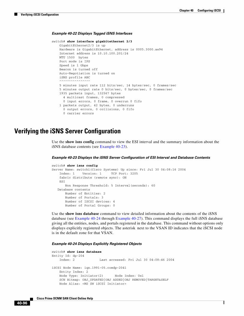
Chapter 40 Configuring iSCSIVerifying iSCSI Configuration
Example 40-22 Displays Tagged iSNS Interfaces
switch# show interface gigabitethernet 2/3 GigabitEthernet2/3 is up Hardware is GigabitEthernet, address is 0005.3000.ae94 Internet address is 10.10.100.201/24 MTU 1500 bytes Port mode is IPS Speed is 1 Gbps Beacon is turned off Auto-Negotiation is turned on iSNS profile ABC ^^^^^^^^^^^^^^^^ 5 minutes input rate 112 bits/sec, 14 bytes/sec, 0 frames/sec 5 minutes output rate 0 bits/sec, 0 bytes/sec, 0 frames/sec 1935 packets input, 132567 bytes 4 multicast frames, 0 compressed 0 input errors, 0 frame, 0 overrun 0 fifo 1 packets output, 42 bytes, 0 underruns 0 output errors, 0 collisions, 0 fifo 0 carrier errors
Verifying the iSNS Server ConfigurationUse the show isns config command to view the ESI interval and the summary information about the iSNS database contents (see Example 40-23).
Example 40-23 Displays the iSNS Server Configuration of ESI Interval and Database Contents
switch# show isns configServer Name: switch1(Cisco Systems) Up since: Fri Jul 30 04:08:16 2004 Index: 1 Version: 1 TCP Port: 3205 fabric distribute (remote sync): ON ESI Non Response Threshold: 5 Interval(seconds): 60 Database contents Number of Entities: 2 Number of Portals: 3 Number of ISCSI devices: 4 Number of Portal Groups: 0
Use the show isns database command to view detailed information about the contents of the iSNS database (see Example 40-24 through Example 40-27). This command displays the full iSNS database giving all the entities, nodes, and portals registered in the database. This command without options only displays explicitly registered objects. The asterisk next to the VSAN ID indicates that the iSCSI node is in the default zone for that VSAN.
Example 40-24 Displays Explicitly Registered Objects
switch# show isns databaseEntity Id: dp-204 Index: 2 Last accessed: Fri Jul 30 04:08:46 2004
iSCSI Node Name: iqn.1991-05.comdp-2041 Entity Index: 2 Node Type: Initiator(2) Node Index: 0x1 SCN Bitmap: OBJ_UPDATED|OBJ ADDED|OBJ REMOVED|TARGET&SELF Node Alias: <MS SW iSCSI Initiator>
40-96Cisco Prime DCNM SAN Client Online Help
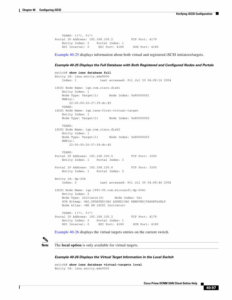
Chapter 40 Configuring iSCSIVerifying iSCSI Configuration
VSANS: 1(*), 5(*)Portal IP Address: 192.168.100.2 TCP Port: 4179 Entity Index: 2 Portal Index: 1 ESI Interval: 0 ESI Port: 4180 SCN Port: 4180
Example 40-25 displays information about both virtual and registered iSCSI initiators/targets.
Example 40-25 Displays the Full Database with Both Registered and Configured Nodes and Portals
switch# show isns database fullEntity Id: isns.entity.mds9000 Index: 1 Last accessed: Fri Jul 30 04:08:16 2004
iSCSI Node Name: iqn.com.cisco.disk1 Entity Index: 1 Node Type: Target(1) Node Index: 0x80000001 WWN(s): 22:00:00:20:37:39:dc:45 VSANS:iSCSI Node Name: iqn.isns-first-virtual-target Entity Index: 1 Node Type: Target(1) Node Index: 0x80000002
VSANS:iSCSI Node Name: iqn.com.cisco.disk2 Entity Index: 1 Node Type: Target(1) Node Index: 0x80000003 WWN(s): 22:00:00:20:37:39:dc:45
VSANS:Portal IP Address: 192.168.100.5 TCP Port: 3205 Entity Index: 1 Portal Index: 3
Portal IP Address: 192.168.100.6 TCP Port: 3205 Entity Index: 1 Portal Index: 5
Entity Id: dp-204 Index: 2 Last accessed: Fri Jul 30 04:08:46 2004
iSCSI Node Name: iqn.1991-05.com.microsoft:dp-2041 Entity Index: 2 Node Type: Initiator(2) Node Index: 0x1 SCN Bitmap: OBJ_UPDATED|OBJ ADDED|OBJ REMOVED|TARGET&SELF Node Alias: <MS SW iSCSI Initiator>
VSANS: 1(*), 5(*)Portal IP Address: 192.168.100.2 TCP Port: 4179 Entity Index: 2 Portal Index: 1 ESI Interval: 0 ESI Port: 4180 SCN Port: 4180
Example 40-26 displays the virtual targets entries on the current switch.
Note The local option is only available for virtual targets.
Example 40-26 Displays the Virtual Target Information in the Local Switch
switch# show isns database virtual-targets localEntity Id: isns.entity.mds9000
40-97Cisco Prime DCNM SAN Client Online Help
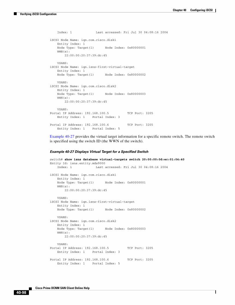
Chapter 40 Configuring iSCSIVerifying iSCSI Configuration
Index: 1 Last accessed: Fri Jul 30 04:08:16 2004
iSCSI Node Name: iqn.com.cisco.disk1 Entity Index: 1 Node Type: Target(1) Node Index: 0x80000001 WWN(s): 22:00:00:20:37:39:dc:45
VSANS:iSCSI Node Name: iqn.isns-first-virtual-target Entity Index: 1 Node Type: Target(1) Node Index: 0x80000002
VSANS:iSCSI Node Name: iqn.com.cisco.disk2 Entity Index: 1 Node Type: Target(1) Node Index: 0x80000003 WWN(s): 22:00:00:20:37:39:dc:45
VSANS:Portal IP Address: 192.168.100.5 TCP Port: 3205 Entity Index: 1 Portal Index: 3
Portal IP Address: 192.168.100.6 TCP Port: 3205 Entity Index: 1 Portal Index: 5
Example 40-27 provides the virtual target information for a specific remote switch. The remote switch is specified using the switch ID (the WWN of the switch).
Example 40-27 Displays Virtual Target for a Specified Switch
switch# show isns database virtual-targets switch 20:00:00:0d:ec:01:04:40Entity Id: isns.entity.mds9000 Index: 1 Last accessed: Fri Jul 30 04:08:16 2004
iSCSI Node Name: iqn.com.cisco.disk1 Entity Index: 1 Node Type: Target(1) Node Index: 0x80000001 WWN(s): 22:00:00:20:37:39:dc:45
VSANS:iSCSI Node Name: iqn.isns-first-virtual-target Entity Index: 1 Node Type: Target(1) Node Index: 0x80000002
VSANS:iSCSI Node Name: iqn.com.cisco.disk2 Entity Index: 1 Node Type: Target(1) Node Index: 0x80000003 WWN(s): 22:00:00:20:37:39:dc:45
VSANS:Portal IP Address: 192.168.100.5 TCP Port: 3205 Entity Index: 1 Portal Index: 3
Portal IP Address: 192.168.100.6 TCP Port: 3205 Entity Index: 1 Portal Index: 5
40-98Cisco Prime DCNM SAN Client Online Help

Chapter 40 Configuring iSCSIVerifying iSCSI Configuration
Use the show isns node command to display attributes of nodes registered with the iSNS server (see Example 40-28 through Example 40-30). If you do not specify any options, the server displays the name and node type attribute in a compact format; one per line.
Example 40-28 Displays Explicitly Registered Objects
switch# show isns node all-------------------------------------------------------------------------------iSCSI Node Name Type-------------------------------------------------------------------------------iqn.1987-05.com.cisco:05.switch1.02-03.22000020375a6c8 Target...iqn.com.cisco.disk1 Targetiqn.com.cisco.ipdisk Targetiqn.isns-first-virtual-target Targetiqn.1991-05.cw22 Targetiqn.1991-05.cw53 Target
Example 40-29 Displays the Specified Node
switch# show isns node name iqn.com.cisco.disk1iSCSI Node Name: iqn.com.cisco.disk1 Entity Index: 1 Node Type: Target(1) Node Index: 0x80000001 WWN(s): 22:00:00:20:37:39:dc:45 VSANS: 1
Example 40-30 Displays the Attribute Details for All Nodes
switch# show isns node all detailiSCSI Node Name: iqn.1987-05.com.cisco:05.switch1.02-03.22000020375a6c8f Entity Index: 1 Node Type: Target(1) Node Index: 0x3000003 Configured Switch WWN: 20:00:00:0d:ec:01:04:40 WWN(s): 22:00:00:20:37:5a:6c:8f VSANS: 1...iSCSI Node Name: iqn.com.cisco.disk1 Entity Index: 1 Node Type: Target(1) Node Index: 0x80000001 Configured Switch WWN: 20:00:00:0d:ec:01:04:40 WWN(s): 22:00:00:20:37:39:dc:45 VSANS: 1
iSCSI Node Name: iqn.com.cisco.ipdisk Entity Index: 1 Node Type: Target(1) Node Index: 0x80000002 Configured Switch WWN: 20:00:00:0d:ec:01:04:40 WWN(s): 22:00:00:20:37:5a:70:1a VSANS: 1
iSCSI Node Name: iqn.isns-first-virtual-target Entity Index: 1 Node Type: Target(1) Node Index: 0x80000003 Configured Switch WWN: 20:00:00:0d:ec:01:04:40
40-99Cisco Prime DCNM SAN Client Online Help

Chapter 40 Configuring iSCSIVerifying iSCSI Configuration
iSCSI Node Name: iqn.parna.121212 Entity Index: 1 Node Type: Target(1) Node Index: 0x80000004 Configured Switch WWN: 20:00:00:0d:ec:01:04:40
iSCSI Node Name: iqn.parna.121213 Entity Index: 1 Node Type: Target(1) Node Index: 0x80000005 Configured Switch WWN: 20:00:00:0d:ec:01:04:40
Use the show isns portal command to display the attributes of a portal along with its accessible nodes (see Example 40-31 through Example 40-35). You can specify portals by using the switch WWN-interface combination or the IP address-port number combination.
Example 40-31 Displays the Attribute Information for All Portals
switch# show isns portal all-------------------------------------------------------------------------------IPAddress TCP Port Index SCN Port ESI port-------------------------------------------------------------------------------192.168.100.5 3205 3 - -192.168.100.6 3205 5 - -
Example 40-32 Displays Detailed Attribute Information for All Portals
switch# show isns portal all detailPortal IP Address: 192.168.100.5 TCP Port: 3205 Entity Index: 1 Portal Index: 3
Portal IP Address: 192.168.100.6 TCP Port: 3205 Entity Index: 1 Portal Index: 5
Example 40-33 Displays Virtual Portals
switch# show isns portal virtual-------------------------------------------------------------------------------IPAddress TCP Port Index SCN Port ESI port-------------------------------------------------------------------------------192.168.100.5 3205 3 - -192.168.100.6 3205 5 - -
Example 40-34 Displays Virtual Portals for the Specified Switch
switch# show isns portal virtual switch 20:00:00:0d:ec:01:04:40-------------------------------------------------------------------------------IPAddress TCP Port Index SCN Port ESI port-------------------------------------------------------------------------------192.168.100.5 3205 3 - -192.168.100.6 3205 5 - -
Example 40-35 Displays Detailed Information for the Virtual Portals in the Specified Switch
switch# show isns portal virtual switch 20:00:00:0d:ec:01:04:40 detailPortal IP Address: 192.168.100.5 TCP Port: 3205 Entity Index: 1 Portal Index: 3
40-100Cisco Prime DCNM SAN Client Online Help

Chapter 40 Configuring iSCSIVerifying iSCSI Configuration
Switch WWN: 20:00:00:0d:ec:01:04:40 Interface: GigabitEthernet2/3
Portal IP Address: 192.168.100.6 TCP Port: 3205 Entity Index: 1 Portal Index: 5 Switch WWN: 20:00:00:0d:ec:01:04:40 Interface: GigabitEthernet2/5
Use the show isns entity command to display the attributes of an entity along with the list of portals and nodes in that entity (see Example 40-36 through Example 40-40). If you do not specify any option, this command displays the entity ID and number of nodes or portals associated with the entity in a compact format; one per line.
Example 40-36 Displays All Registered Entries
switch1# show isns entity-------------------------------------------------------------------------------Entity ID Last Accessed-------------------------------------------------------------------------------dp-204 Tue Sep 7 23:15:42 2004
Example 40-37 Displays All Entities in the Database
switch# show isns entity all
-------------------------------------------------------------------------------Entity ID Last Accessed-------------------------------------------------------------------------------isns.entity.mds9000 Tue Sep 7 21:33:23 2004
dp-204 Tue Sep 7 23:15:42 2004
Example 40-38 Displays the Entity with the Specified ID
switch1# show isns entity id dp-204Entity Id: dp-204 Index: 2 Last accessed: Tue Sep 7 23:15:42 2004
Example 40-39 Displays Detailed Information for All Entities in the Database
switch1# show isns entity all detailEntity Id: isns.entity.mds9000 Index: 1 Last accessed: Tue Sep 7 21:33:23 2004
Entity Id: dp-204 Index: 2 Last accessed: Tue Sep 7 23:16:34 2004
Example 40-40 Displays Virtual Entities
switch# show isns entity virtualEntity Id: isns.entity.mds9000 Index: 1 Last accessed: Thu Aug 5 00:58:50 2004
Entity Id: dp-204 Index: 2 Last accessed: Thu Aug 5 01:00:23 2004
40-101Cisco Prime DCNM SAN Client Online Help
Chapter 40 Configuring iSCSIVerifying iSCSI Configuration
Use the show iscsi global config command to display information about import targets (see Example 40-41 and Example 40-42).
Example 40-41 Displays the Import Target Settings for the Specified Switch
switch# show isns iscsi global config switch 20:00:00:05:ec:01:04:00iSCSI Global configuration: Switch: 20:00:00:05:ec:01:04:00 iSCSI Auto Import: Enabled
Example 40-42 Displays the Import Target Settings for All Switches
switch# show isns iscsi global config alliSCSI Global configuration: Switch: 20:00:44:0d:ec:01:02:40 iSCSI Auto Import: Enabled
Use the show cfs peers command to display CFS peers switch information about the iSNS application (see Example 40-43).
Example 40-43 Displays the CFS Peer Switch Information for the iSNS Application
switch# show cfs peers name isns
Scope : Physical-------------------------------------------------- Switch WWN IP Address-------------------------------------------------- 20:00:00:00:ec:01:00:40 10.10.100.11 [Local]
Total number of entries = 1
Verifying Automatic iSNS Cloud Discovery ConfigurationTo verify the automatic iSNS cloud discovery configuration, use the show cloud discovery config command.
switch# show cloud discovery configAuto discovery: Enabled
Verifying Cloud Discovery StatusUse the show cloud discovery status command to verify the status of the cloud discovery operation.
switch# show cloud discovery statusDiscovery status: Succeeded
Verifying Cloud Discovery MembershipUse the show cloud membership all command to verify the cloud membership for the switch.
switch# show cloud membership allCloud 2
40-102Cisco Prime DCNM SAN Client Online Help

Chapter 40 Configuring iSCSIConfiguration Examples for iSCSI
GigabitEthernet1/5[20:00:00:0d:ec:02:c6:c0] IP Addr 10.10.10.5 GigabitEthernet1/6[20:00:00:0d:ec:02:c6:c0] IP Addr 10.10.10.6 #members=2
Use the show cloud membership unresolved command to verify the unresolved membership on the switch.
switch# show cloud membership unresolvedUndiscovered Cloud No members
Displaying Cloud Discovery StatisticsUse the show cloud discovery statistics command to display the statistics for the cloud discovery operation.
switch# show cloud discovery statisticsGlobal statistics Number of Auto Discovery = 1 Number of Manual Discovery = 0 Number of cloud discovery (ping) messages sent = 1 Number of cloud discovery (ping) success = 1
Configuration Examples for iSCSIThis section provides three examples of iSCSI virtual target configurations.
Example 1
This example assigns the whole Fibre Channel target as an iSCSI virtual target. All LUNs that are part of the Fibre Channel target are available as part of the iSCSI target (see Figure 40-17).
Figure 40-17 Assigning iSCSI Node Names
iscsi virtual-target name iqn.1987-02.com.cisco.target-1pWWN 28:00:01:02:03:04:05:06
1
23
4
56
iSCSI view of storage deviceiqn.1987-02.com.cisco.target-1
1
23
4
56
Fibre Channel storagedevice
pWWN 28:00:01:02:03:04:05:06
1121
89
40-103Cisco Prime DCNM SAN Client Online Help
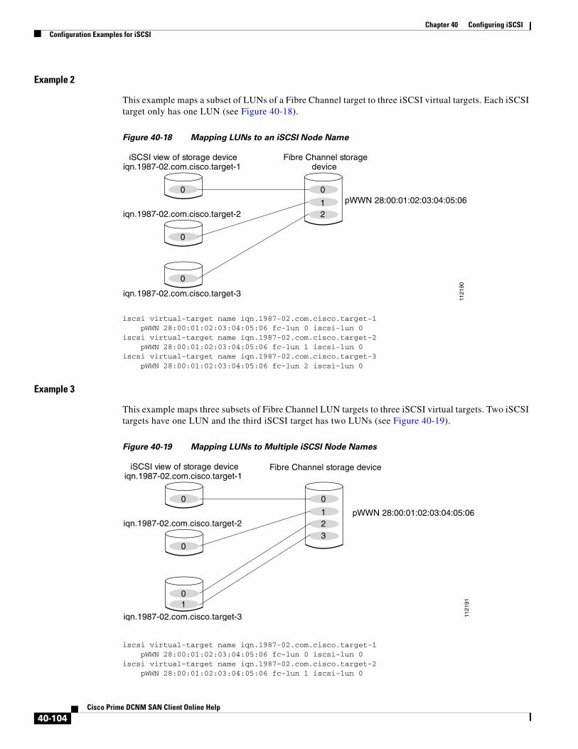
Chapter 40 Configuring iSCSIConfiguration Examples for iSCSI
Example 2
This example maps a subset of LUNs of a Fibre Channel target to three iSCSI virtual targets. Each iSCSI target only has one LUN (see Figure 40-18).
Figure 40-18 Mapping LUNs to an iSCSI Node Name
iscsi virtual-target name iqn.1987-02.com.cisco.target-1 pWWN 28:00:01:02:03:04:05:06 fc-lun 0 iscsi-lun 0iscsi virtual-target name iqn.1987-02.com.cisco.target-2 pWWN 28:00:01:02:03:04:05:06 fc-lun 1 iscsi-lun 0iscsi virtual-target name iqn.1987-02.com.cisco.target-3 pWWN 28:00:01:02:03:04:05:06 fc-lun 2 iscsi-lun 0
Example 3
This example maps three subsets of Fibre Channel LUN targets to three iSCSI virtual targets. Two iSCSI targets have one LUN and the third iSCSI target has two LUNs (see Figure 40-19).
Figure 40-19 Mapping LUNs to Multiple iSCSI Node Names
iscsi virtual-target name iqn.1987-02.com.cisco.target-1 pWWN 28:00:01:02:03:04:05:06 fc-lun 0 iscsi-lun 0iscsi virtual-target name iqn.1987-02.com.cisco.target-2 pWWN 28:00:01:02:03:04:05:06 fc-lun 1 iscsi-lun 0
0
iSCSI view of storage deviceiqn.1987-02.com.cisco.target-1
0
0
0
12
Fibre Channel storagedevice
pWWN 28:00:01:02:03:04:05:06
1121
90
iqn.1987-02.com.cisco.target-2
iqn.1987-02.com.cisco.target-3
0
iSCSI view of storage deviceiqn.1987-02.com.cisco.target-1
0
01
0
123
Fibre Channel storage device
pWWN 28:00:01:02:03:04:05:06iqn.1987-02.com.cisco.target-2
iqn.1987-02.com.cisco.target-3 1121
91
40-104Cisco Prime DCNM SAN Client Online Help

Chapter 40 Configuring iSCSIConfiguration Examples for iSCSI
iscsi virtual-target name iqn.1987-02.com.cisco.target-3 pWWN 28:00:01:02:03:04:05:06 fc-lun 2 iscsi-lun 0 pWWN 28:00:01:02:03:04:05:06 fc-lun 3 iscsi-lun 1
Example of VSAN Membership for iSCSI Devices
Figure 40-20 provides an example of VSAN membership for iSCSI devices:
• iSCSI interface 1/1 is a member of VSAN Y.
• iSCSI initiator host A has explicit VSAN membership to VSAN X.
• Three iSCSI initiators (host A, host B, and host C) C connect to iSCSI interface 1/1.
Figure 40-20 VSAN Membership for iSCSI Interfaces
Host A’s virtual Fibre Channel N port will be added to VSAN X because of explicit membership for the initiator. The virtual host-B and host-C N ports do not have any explicit membership configuration so they will inherit the iSCSI interface VSAN membership and be part of VSAN Y.
Example 40-44 and Example 40-45 are based on the following configurations:
• GigabitEthernet2/1.441 is the VRRP master interface for Switch1.
• GigabitEthernet2/2.441 is the VRRP backup interface for Switch1.
• GigabitEthernet1/1.441 is the VRRP backup interface for Switch2.
• GigabitEthernet1/2.441 is the VRRP backup interface for Switch2.
Example 40-44 Load Distribution with the Default Metric
The follow example output shows the initial load distribution for three initiators with the default load metric value:
switch# show islb vrrp summary...--------------------------------------------------------------------------------VR Id VRRP IP Switch WWN Ifindex Load
iSCSIiSCSI
Host B
iSCSIiSCSI
Host A(VSAN X)
iSCSIiSCSI
Host C
MDS
VirtualHost A
VirtualHost C
VirtualHost B
T1
1208
70
IPnetwork
T2
VSAN Y
VSAN X
VSAN Y
VSAN X
iSCSI interface 1/1 port VSAN = Y
40-105Cisco Prime DCNM SAN Client Online Help

Chapter 40 Configuring iSCSIConfiguration Examples for iSCSI
--------------------------------------------------------------------------------M 1 10.10.122.115 20:00:00:0b:5f:3c:01:80 GigabitEthernet2/1.441 0 1 10.10.122.115 20:00:00:0b:5f:3c:01:80 GigabitEthernet2/2.441 1000 1 10.10.122.115 20:00:00:0c:ce:5c:5b:c0 GigabitEthernet1/1.441 1000 1 10.10.122.115 20:00:00:0c:ce:5c:5b:c0 GigabitEthernet1/2.441 1000 -- Initiator To Interface Assignment ----------------------------------------------------------------------------------Initiator VR Id VRRP IP Switch WWN Ifindex--------------------------------------------------------------------------------iqn.cisco.test-linux.init0 1 10.10.122.115 20:00:00:0b:5f:3c:01:80 GigabitEthernet2/2.441iqn.cisco.test-linux.init1 1 10.10.122.115 20:00:00:0c:ce:5c:5b:c0 GigabitEthernet1/1.441iqn.cisco.test-linux.init 1 10.10.122.115 20:00:00:0c:ce:5c:5b:c0 GigabitEthernet1/2.441
The following example output shows load distribution for four initiators. The interface load metric value for the master interface changed from 0 to 1000.
switch# show islb vrrp summary...--------------------------------------------------------------------------------VVR Id VRRP IP Switch WWN Ifindex Load--------------------------------------------------------------------------------M 1 10.10.122.115 20:00:00:0b:5f:3c:01:80 GigabitEthernet2/1.441 1000 1 10.10.122.115 20:00:00:0b:5f:3c:01:80 GigabitEthernet2/2.441 1000 1 10.10.122.115 20:00:00:0c:ce:5c:5b:c0 GigabitEthernet1/1.441 1000 1 10.10.122.115 20:00:00:0c:ce:5c:5b:c0 GigabitEthernet1/2.441 1000 -- Initiator To Interface Assignment ----------------------------------------------------------------------------------Initiator VR Id VRRP IP Switch WWN Ifindex--------------------------------------------------------------------------------iqn.cisco.test-linux.init0 1 10.10.122.115 20:00:00:0b:5f:3c:01:80 GigabitEthernet2/2.441iqn.cisco.test-linux.init1 1 10.10.122.115 20:00:00:0c:ce:5c:5b:c0 GigabitEthernet1/1.441iqn.cisco.test-linux.init2 1 10.10.122.115 20:00:00:0c:ce:5c:5b:c0 GigabitEthernet1/2.441iqn.cisco.test-linux.init3 1 10.10.122.115 20:00:00:0b:5f:3c:01:80 GigabitEthernet2/1.441
The following example output shows load distribution for nine initiators. The interface load metric values for the backup interfaces have changed.
switch# show islb vrrp summary...--------------------------------------------------------------------------------VVR Id VRRP IP Switch WWN Ifindex Load--------------------------------------------------------------------------------M 1 10.10.122.115 20:00:00:0b:5f:3c:01:80 GigabitEthernet2/1.441 1000 1 10.10.122.115 20:00:00:0b:5f:3c:01:80 GigabitEthernet2/2.441 3000 1 10.10.122.115 20:00:00:0c:ce:5c:5b:c0 GigabitEthernet1/1.441 3000 1 10.10.122.115 20:00:00:0c:ce:5c:5b:c0 GigabitEthernet1/2.441 2000 -- Initiator To Interface Assignment ----------------------------------------------------------------------------------Initiator VR Id VRRP IP Switch WWN Ifindex--------------------------------------------------------------------------------iqn.cisco.test-linux.init0 1 10.10.122.115 20:00:00:0b:5f:3c:01:80 GigabitEthernet2/2.441iqn.cisco.test-linux.init1 1 10.10.122.115 20:00:00:0c:ce:5c:5b:c0 GigabitEthernet1/1.441iqn.cisco.test-linux.init2 1 10.10.122.115 20:00:00:0c:ce:5c:5b:c0 GigabitEthernet1/2.441iqn.cisco.test-linux.init3 1 10.10.122.115 20:00:00:0b:5f:3c:01:80 GigabitEthernet2/1.441iqn.cisco.test-linux.init4 1 10.10.122.115 20:00:00:0b:5f:3c:01:80 GigabitEthernet2/2.441iqn.cisco.test-linux.init5 1 10.10.122.115 20:00:00:0c:ce:5c:5b:c0 GigabitEthernet1/1.441iqn.cisco.test-linux.init6 1 10.10.122.115 20:00:00:0c:ce:5c:5b:c0 GigabitEthernet1/2.441iqn.cisco.test-linux.init7 1 10.10.122.115 20:00:00:0b:5f:3c:01:80 GigabitEthernet2/2.441iqn.cisco.test-linux.init8 1 10.10.122.115 20:00:00:0c:ce:5c:5b:c0 GigabitEthernet1/1.441
40-106Cisco Prime DCNM SAN Client Online Help

Chapter 40 Configuring iSCSIConfiguration Examples for iSCSI
Example 40-45 Load Distribution with the Metric Set to 3000 on One Initiator
The following example output shows the initial load distribution for three initiators with one initiator having load metric of 3000 and the remaining initiator with the default metric value:
switch# show islb vrrp summary...--------------------------------------------------------------------------------VVR Id VRRP IP Switch WWN Ifindex Load--------------------------------------------------------------------------------M 1 10.10.122.115 20:00:00:0b:5f:3c:01:80 GigabitEthernet2/1.441 0 1 10.10.122.115 20:00:00:0b:5f:3c:01:80 GigabitEthernet2/2.441 1000 1 10.10.122.115 20:00:00:0c:ce:5c:5b:c0 GigabitEthernet1/1.441 3000 1 10.10.122.115 20:00:00:0c:ce:5c:5b:c0 GigabitEthernet1/2.441 1000 -- Initiator To Interface Assignment ----------------------------------------------------------------------------------Initiator VR Id VRRP IP Switch WWN Ifindex--------------------------------------------------------------------------------iqn.cisco.test-linux.init0 1 10.10.122.115 20:00:00:0c:ce:5c:5b:c0 GigabitEthernet1/1.441iqn.cisco.test-linux.init1 1 10.10.122.115 20:00:00:0b:5f:3c:01:80 GigabitEthernet2/2.441iqn.cisco.test-linux.init2 1 10.10.122.115 20:00:00:0c:ce:5c:5b:c0 GigabitEthernet1/2.441
The follow example output shows load distribution for four initiators. The interface load metric value for the master interface changed from 0 to 1000.
switch# show islb vrrp summary...--------------------------------------------------------------------------------VVR Id VRRP IP Switch WWN Ifindex Load--------------------------------------------------------------------------------M 1 10.10.122.115 20:00:00:0b:5f:3c:01:80 GigabitEthernet2/1.441 1000 1 10.10.122.115 20:00:00:0b:5f:3c:01:80 GigabitEthernet2/2.441 3000 1 10.10.122.115 20:00:00:0c:ce:5c:5b:c0 GigabitEthernet1/1.441 1000 1 10.10.122.115 20:00:00:0c:ce:5c:5b:c0 GigabitEthernet1/2.441 1000 -- Initiator To Interface Assignment ----------------------------------------------------------------------------------Initiator VR Id VRRP IP Switch WWN Ifindex--------------------------------------------------------------------------------iqn.cisco.test-linux.init0 1 10.10.122.115 20:00:00:0b:5f:3c:01:80 GigabitEthernet2/2.441iqn.cisco.test-linux.init1 1 10.10.122.115 20:00:00:0c:ce:5c:5b:c0 GigabitEthernet1/2.441iqn.cisco.test-linux.init2 1 10.10.122.115 20:00:00:0c:ce:5c:5b:c0 GigabitEthernet1/1.441iqn.cisco.test-linux.init3 1 10.10.122.115 20:00:00:0b:5f:3c:01:80 GigabitEthernet2/1.441
The following example output shows load distribution for nine initiators. The interface load metric values for the backup interfaces have changed.
switch# show islb vrrp summary...--------------------------------------------------------------------------------VVR Id VRRP IP Switch WWN Ifindex Load--------------------------------------------------------------------------------M 1 10.10.122.115 20:00:00:0b:5f:3c:01:80 GigabitEthernet2/1.441 2000 1 10.10.122.115 20:00:00:0b:5f:3c:01:80 GigabitEthernet2/2.441 3000 1 10.10.122.115 20:00:00:0c:ce:5c:5b:c0 GigabitEthernet1/1.441 3000 1 10.10.122.115 20:00:00:0c:ce:5c:5b:c0 GigabitEthernet1/2.441 3000 -- Initiator To Interface Assignment ----------------------------------------------------------------------------------Initiator VR Id VRRP IP Switch WWN Ifindex--------------------------------------------------------------------------------iqn.cisco.test-linux.init0 1 10.10.122.115 20:00:00:0b:5f:3c:01:80 GigabitEthernet2/2.441iqn.cisco.test-linux.init1 1 10.10.122.115 20:00:00:0c:ce:5c:5b:c0 GigabitEthernet1/1.441iqn.cisco.test-linux.init2 1 10.10.122.115 20:00:00:0c:ce:5c:5b:c0 GigabitEthernet1/2.441iqn.cisco.test-linux.init3 1 10.10.122.115 20:00:00:0b:5f:3c:01:80 GigabitEthernet2/1.441iqn.cisco.test-linux.init4 1 10.10.122.115 20:00:00:0c:ce:5c:5b:c0 GigabitEthernet1/1.441
40-107Cisco Prime DCNM SAN Client Online Help

Chapter 40 Configuring iSCSIConfiguration Examples for iSCSI
iqn.cisco.test-linux.init5 1 10.10.122.115 20:00:00:0c:ce:5c:5b:c0 GigabitEthernet1/2.441iqn.cisco.test-linux.init6 1 10.10.122.115 20:00:00:0c:ce:5c:5b:c0 GigabitEthernet1/1.441iqn.cisco.test-linux.init7 1 10.10.122.115 20:00:00:0c:ce:5c:5b:c0 GigabitEthernet1/2.441iqn.cisco.test-linux.init8 1 10.10.122.115 20:00:00:0b:5f:3c:01:80 GigabitEthernet2/1.441
Example of an iSNS Server
The iSNS server provides uniform access control across Fibre Channel and iSCSI devices by utilizing both Fibre Channel zoning information and iSCSI access control information and configuration. An iSCSI initiator acting as an iSNS client only discovers devices it is allowed to access based on both sets of access control information. Figure 40-21 provides an example of this scenario.
Figure 40-21 Using iSNS Servers in the Cisco MDS Environment
In Figure 40-21, iqn.host1 and iqn.host2 are iSCSI initiators. P1 and P2 are Fibre Channel targets. The two initiators are in different zones: Zone 1 consists of iqn.host1 and target P1, and Zone 2 consists of iqn.host2 and target P2. iSNS server functionality is enabled on both switches, SW-1 and SW-2. The registration process proceeds as follows:
1. Initiator iqn.host1 registers with SW-1, port Gigabitethernet2/1.
2. Initiator iqn.host2 registers with SW-2, port Gigabitethernet3/1.
3. Initiator iqn.host1 issues an iSNS query to SW-1 to determine all accessible targets.
4. The iSNS server in turn queries the Fibre Channel name server (FCNS) to obtain a list of devices that are accessible (that is, in the same zone) by the query originator. This query yields only P1.
5. The iSNS server then queries its own database to convert the Fibre Channel devices to the corresponding iSCSI targets. This is based on the iSCSI configuration, such as virtual-target and its access control setting or whether the dynamic Fibre Channel target import feature is enabled or disabled.
6. The iSNS server sends a response back to the query initiator. This response contains a list all iSCSI portals known to the iSNS server. This means iqn.host1 can choose to log in to target P1 through either SW-1 (at Gigabitethernet 2/1) or SW-2 (at Gigabitethernet 3/1).
7. If the initiator chooses to log in to SW-1 and later that port becomes inaccessible (for example, Gigabitethernet 2/1 goes down), the initiator has the choice to move to connect to target P1 through port Gigabitethernet 3/1 on SW-2 instead.
FC FC
iSCSITOE
iSCSITOE
IPNetwork - 1
iqn.host1 iqn.host2
P1 SW-1 SW-2 P2
Zone 1 Zone 2
1309
14
Gigabitethernet 3/1Gigabitethernet 2/1
40-108Cisco Prime DCNM SAN Client Online Help
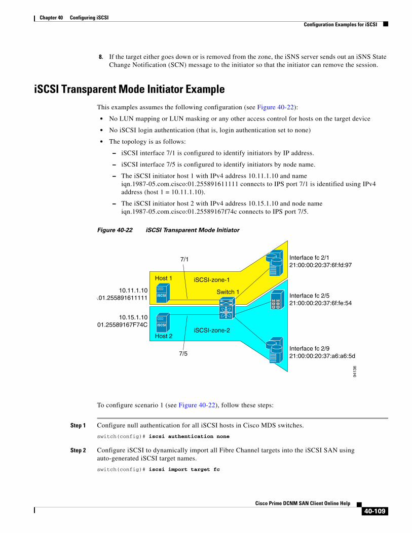
Chapter 40 Configuring iSCSIConfiguration Examples for iSCSI
8. If the target either goes down or is removed from the zone, the iSNS server sends out an iSNS State Change Notification (SCN) message to the initiator so that the initiator can remove the session.
iSCSI Transparent Mode Initiator ExampleThis examples assumes the following configuration (see Figure 40-22):
• No LUN mapping or LUN masking or any other access control for hosts on the target device
• No iSCSI login authentication (that is, login authentication set to none)
• The topology is as follows:
– iSCSI interface 7/1 is configured to identify initiators by IP address.
– iSCSI interface 7/5 is configured to identify initiators by node name.
– The iSCSI initiator host 1 with IPv4 address 10.11.1.10 and name iqn.1987-05.com.cisco:01.255891611111 connects to IPS port 7/1 is identified using IPv4 address (host 1 = 10.11.1.10).
– The iSCSI initiator host 2 with IPv4 address 10.15.1.10 and node name iqn.1987-05.com.cisco:01.25589167f74c connects to IPS port 7/5.
Figure 40-22 iSCSI Transparent Mode Initiator
To configure scenario 1 (see Figure 40-22), follow these steps:
Step 1 Configure null authentication for all iSCSI hosts in Cisco MDS switches.
switch(config)# iscsi authentication none
Step 2 Configure iSCSI to dynamically import all Fibre Channel targets into the iSCSI SAN using auto-generated iSCSI target names.
switch(config)# iscsi import target fc
iSCSI
iSCSI
Host 1
Host 2
Switch 1
7/1
7/5
iSCSI-zone-1
iSCSI-zone-2
Interface fc 2/121:00:00:20:37:6f:fd:97
Interface fc 2/521:00:00:20:37:6f:fe:54
Interface fc 2/921:00:00:20:37:a6:a6:5d
9413
6
10.11.1.10o.01.255891611111
10.15.1.10.01.25589167F74C
40-109Cisco Prime DCNM SAN Client Online Help
Chapter 40 Configuring iSCSIConfiguration Examples for iSCSI
Step 3 Configure the Gigabit Ethernet interface in slot 7 port 1 with an IPv4 address and enable the interface.
switch(config)# interface gigabitethernet 7/1 switch(config-if)# ip address 10.11.1.1 255.255.255.0 switch(config-if)# no shutdown
Note Host 2 is connected to this port.
Step 4 Configure the iSCSI interface in slot 7 port 1 to identify all dynamic iSCSI initiators by their IP address, and enable the interface.
switch(config)# interface iscsi 7/1switch(config-if)# switchport initiator id ip-address switch(config-if)# no shut
Step 5 Configure the Gigabit Ethernet interface in slot 7 port 5 with the IPv4 address and enable the interface.
switch(config)# interface gigabitethernet 7/5switch(config-if)# ip address 10.15.1.1 255.255.255.0switch(config-if)# no shutdown
Step 6 Configure the iSCSI interface in slot 7 port 5 to identify all dynamic iSCSI initiators by node name and enable the interface.
switch(config)# interface iscsi 7/5switch(config-if)# switchport initiator id name switch(config-if)# no shutdown
Note Host 1 is connected to this port.
Step 7 Verify the available Fibre Channel targets (see Figure 40-22).
switch# show fcns database VSAN 1:--------------------------------------------------------------------------FCID TYPE PWWN (VENDOR) FC4-TYPE:FEATURE--------------------------------------------------------------------------0x6d0001 NL 21:00:00:20:37:6f:fd:97 (Seagate) scsi-fcp:target 0x6d0101 NL 21:00:00:20:37:6f:fe:54 (Seagate) scsi-fcp:target 0x6d0201 NL 21:00:00:20:37:a6:a6:5d (Seagate) scsi-fcp:target Total number of entries = 3
Step 8 Create a zone named iscsi-zone-1 with host 1 and one Fibre Channel target in it.
Note Use the IP address of the host in zone membership configuration because the iSCSI interface is configured to identify all hosts based on IP address.
switch(config)# zone name iscsi-zone-1 vsan 1switch(config-zone)# member pwwn 21:00:00:20:37:6f:fd:97 switch(config-zone)# member ip-address 10.11.1.10
Step 9 Create a zone named iscsi-zone-2 with host 2 and two Fibre Channel targets in it.
Note Use the symbolic node name of the iSCSI host in zone membership configuration because the iSCSI interface is configured to identify all hosts based on node name.
40-110Cisco Prime DCNM SAN Client Online Help

Chapter 40 Configuring iSCSIConfiguration Examples for iSCSI
switch(config)# zone name iscsi-zone-2 vsan 1switch(config-zone)# member pwwn 21:00:00:20:37:6f:fe:54switch(config-zone)# member pwwn 21:00:00:20:37:a6:a6:5dswitch(config-zone)# member symbolic-nodename iqn.1987-05.com.cisco:01.25589167f74c
Step 10 Create a zone set and add the two zones as members.
switch(config)# zoneset name zoneset-iscsi vsan 1switch(config-zoneset)# member iscsi-zone-1switch(config-zoneset)# member iscsi-zone-2
Step 11 Activate the zone set.
switch(config)# zoneset activate name zoneset-iscsi vsan 1
Step 12 Display the active zone set.
Note The iSCSI hosts are not connected so they do not have an FC ID yet.
switch# show zoneset active zoneset name zoneset-iscsi vsan 1 zone name iscsi-zone-1 vsan 1 * fcid 0x6d0001 [pwwn 21:00:00:20:37:6f:fd:97] <-----------Target symbolic-nodename 10.11.1.10 <--------------------------------- iSCSI host (host 1, not online)
zone name iscsi-zone-2 vsan 1 * fcid 0x6d0101 [pwwn 21:00:00:20:37:6f:fe:54] <------------Target * fcid 0x6d0201 [pwwn 21:00:00:20:37:a6:a6:5d] <------------Target symbolic-nodename iqn.1987-05.com.cisco:01.25589167f74c <-iSCSI host (host 2, not online)
Step 13 Bring up the iSCSI hosts (host 1 and host 2).
Step 14 Show all the iSCSI sessions (use the detail option for detailed information).
switch# show iscsi session Initiator iqn.1987-05.com.cisco:01.25589167f74c <-----Host 2 Initiator ip addr (s): 10.15.1.11
Session #1 Target iqn.1987-05.com.cisco:05.172.22.92.166.07-05.21000020376ffe54
Note The last part of the auto-created target name is the Fibre Channel target's pWWN.
VSAN 1, ISID 00023d000001, Status active, no reservation
Session #2 Target iqn.1987-05.com.cisco:05.172.22.92.166.07-05.2100002037a6a65d VSAN 1, ISID 00023d000001, Status active, no reservation
Initiator 10.11.1.10 <-----------------------------------Host 1 Initiator name iqn.1987-05.com.cisco:01.e41695d16b1a Session #1 Target iqn.1987-05.com.cisco:05.172.22.92.166.07-01.21000020376ffd97 VSAN 1, ISID 00023d000001, Status active, no reservation
40-111Cisco Prime DCNM SAN Client Online Help

Chapter 40 Configuring iSCSIConfiguration Examples for iSCSI
Step 15 Verify the details of the two iSCSI initiators.
Step 16 View the active zone set. The iSCSI initiators' FC IDs are resolved.
Step 17 The Fibre Channel name server shows the virtual N ports created for the iSCSI hosts.
switch# show fcns database VSAN 1:--------------------------------------------------------------------------FCID TYPE PWWN (VENDOR) FC4-TYPE:FEATURE--------------------------------------------------------------------------0x6d0001 NL 21:00:00:20:37:6f:fd:97 (Seagate) scsi-fcp:target 0x6d0101 NL 21:00:00:20:37:6f:fe:54 (Seagate) scsi-fcp:target 0x6d0201 NL 21:00:00:20:37:a6:a6:5d (Seagate) scsi-fcp:target 0x6d0300 N 20:03:00:0b:fd:44:68:c2 (Cisco) scsi-fcp:init isc..w 0x6d0301 N 20:05:00:0b:fd:44:68:c2 (Cisco) scsi-fcp:init isc..w
switch# show iscsi initiator iSCSI Node name is iqn.1987-05.com.cisco:01.25589167f74c <--------- Initiator ip addr (s): 10.15.1.11 iSCSI alias name: oasis11.cisco.com Node WWN is 20:02:00:0b:fd:44:68:c2 (dynamic) Member of vsans: 1 Number of Virtual n_ports: 1 Virtual Port WWN is 20:03:00:0b:fd:44:68:c2 (dynamic) Interface iSCSI 7/5, Portal group tag: 0x304 VSAN ID 1, FCID 0x6d0300
Host 2: Initiator ID based on node name because the initiator is entering iSCSI interface 7/5
iSCSI Node name is 10.11.1.10 <------------------------ iSCSI Initiator name: iqn.1987 - 05.com.cisco:01.e41695d16b1a iSCSI alias name: oasis10.cisco.com Node WWN is 20:04:00:0b:fd:44:68:c2 (dynamic) Member of vsans: 1 Number of Virtual n_ports: 1 Virtual Port WWN is 20:05:00:0b:fd:44:68:c2 (dynamic) Interface iSCSI 7/1, Portal group tag: 0x300 VSAN ID 1, FCID 0x6d0301
Host 1: Initiator ID based on IPv4 address because the initiator is entering iSCSI interface 7/1
switch# show zoneset active zoneset name zoneset-iscsi vsan 1 zone name iscsi-zone-1 vsan 1 * fcid 0x6d0001 [pwwn 21:00:00:20:37:6f:fd:97] * fcid 0x6d0301 [symbolic-nodename 10.11.1.10] <-------------
FC ID resolved for host 1
zone name iscsi-zone-2 vsan 1 * fcid 0x6d0101 [pwwn 21:00:00:20:37:6f:fe:54] * fcid 0x6d0201 [pwwn 21:00:00:20:37:a6:a6:5d] * fcid 0x6d0300 [symbolic-nodename iqn.1987-05.com.cisco:01.25589167f74c]<------------------------- FC ID for host 2
40-112Cisco Prime DCNM SAN Client Online Help

Chapter 40 Configuring iSCSIConfiguration Examples for iSCSI
Step 18 Verify the detailed output of the iSCSI initiator nodes in the Fibre Channel name server.
To configure this example(see Figure 40-22), follow these steps:
Step 1 Configure null authentication for all iSCSI hosts in Cisco MDS switches.
a. In Cisco DCNM-SAN, choose End Devices > iSCSI in the Physical Attributes pane.
b. Select none from the AuthMethod drop-down menu in the Information pane.
c. Click the Apply Changes icon.
Step 2 Configure iSCSI to dynamically import all Fibre Channel targets into the iSCSI SAN using auto-generated iSCSI target names.
a. In Device Manager, click IP > iSCSI.
b. Click the Targets tab.
c. Check the Dynamically Import FC Targets check box.
switch# show fcns database fcid 0x6d0300 detail vsan 1------------------------VSAN:1 FCID:0x6d0300------------------------port-wwn (vendor) :20:03:00:0b:fd:44:68:c2 (Cisco) node-wwn :20:02:00:0b:fd:44:68:c2class :2,3node-ip-addr :10.15.1.11 <---------------------- ipa :ff ff ff ff ff ff ff fffc4-types:fc4_features:scsi-fcp:init iscsi-gw <------symbolic-port-name :
IPv4 address of the iSCSI host
iSCSI gateway node
symbolic-node-name :iqn.1987-05.com.cisco:01.25589167f74c<--------------------port-type :N port-ip-addr :0.0.0.0fabric-port-wwn :21:91:00:0b:fd:44:68:c0hard-addr :0x000000Total number of entries = 1
iSCSI initiator ID is based on the registered node name
switch# show fcns database fcid 0x6d0301 detail vsan 1------------------------VSAN:1 FCID:0x6d0301------------------------port-wwn (vendor) :20:05:00:0b:fd:44:68:c2 (Cisco) node-wwn :20:04:00:0b:fd:44:68:c2class :2,3node-ip-addr :10.11.1.10ipa :ff ff ff ff ff ff ff fffc4-types:fc4_features:scsi-fcp:init iscsi-gw <------ symbolic-port-name :
iSCSI gateway node
symbolic-node-name :10.11.1.10 <---------------------port-type :N port-ip-addr :0.0.0.0fabric-port-wwn :21:81:00:0b:fd:44:68:c0hard-addr :0x000000
iSCSI initiator ID is based on the IPv4 address registered in symbolic-node-name field
40-113Cisco Prime DCNM SAN Client Online Help

Chapter 40 Configuring iSCSIConfiguration Examples for iSCSI
d. Click Apply.
Step 3 Configure the Gigabit Ethernet interface in slot 7 port 1 with an IPv4 address and enable the interface.
a. In Cisco DCNM-SAN, choose Switches > Interfaces > Gigabit Ethernet in the Physical Attributes pane.
b. Select the IP Address tab in the Information pane and click Create Row.
c. Set the IP address and subnet mask for the Gigabit Ethernet interface in slot 7 port 1.
d. Click Create.
e. Select the General tab and select up from the Admin drop-down menu for the Gigabit Ethernet interface in slot 7 port 1.
f. Click the Apply Changes icon.
Note Host 2 is connected to this port.
Step 4 Configure the iSCSI interface in slot 7 port 1 to identify all dynamic iSCSI initiators by their IP address, and enable the interface.
a. In Cisco DCNM-SAN, choose Switches > Interfaces > FC Logical in the Physical Attributes pane.
b. Click the iSCSI tab in the Information pane.
c. Select ipaddress from the Initiator ID Mode drop-down menu and click the Apply Changes icon.
d. In Device Manager, choose Interfaces > Ethernet and iSCSI.
e. Click the iSCSI tab.
f. Select up from the Admin drop-down menu for the iSCSI interface in slot 7 port 1.
g. Click Apply.
Step 5 Configure the Gigabit Ethernet interface in slot 7 port 5 with an IPv4 address and enable the interface.
a. In Cisco DCNM-SAN, choose Switches > Interfaces > Gigabit Ethernet in the Physical Attributes pane.
b. Click the IP Address tab in the Information pane and click Create Row.
c. Set the IP address and subnet mask for the Gigabit Ethernet interface in slot 7 port 5.
d. Click Create.
e. Select the General tab and select up from the Admin drop-down menu for the Gigabit Ethernet interface in slot 7 port 5.
f. Click the Apply Changes icon.
Step 6 Configure the iSCSI interface in slot 7 port 5 to identify all dynamic iSCSI initiators by node name and enable the interface.
a. In Cisco DCNM-SAN, choose Switches > Interfaces > FC Logical in the Physical Attributes pane.
b. Click the iSCSI tab in the Information pane.
c. Select name from the Initiator ID Mode drop-down menu and click the Apply Changes icon.
d. In Device Manager, choose Interfaces > Ethernet and iSCSI.
e. Click the iSCSI tab.
f. Select up from the Admin drop-down menu for the iSCSI interface in slot 7 port 5.
g. Click Apply.
40-114Cisco Prime DCNM SAN Client Online Help

Chapter 40 Configuring iSCSIConfiguration Examples for iSCSI
Note Host 1 is connected to this port.
Step 7 Verify the available Fibre Channel targets.
a. In Device Manager, Choose FC > Name Server.
b. Click the General tab.
Step 8 Create a zone named iscsi-zone-1 with host 1 and one Fibre Channel target in it.
Note Use the IP address of the host in zone membership configuration because the iSCSI interface is configured to identify all hosts based on IP address.
a. In Cisco DCNM-SAN, choose Zones > Edit Local Full Zone Database.
b. Select VSAN 1 from the VSAN drop-down menu in the Edit Local Full Zone Database dialog box.
c. Select the Zones folder in the left navigation pane and click Insert.
d. Set the Zone Name field to iscsi-zone-1 and click OK.
e. Select the iscsi-zone-1 folder in the left navigation pane and click Insert.
f. Set the ZoneBy radio button toWWN.
g. Set the Port WWN to the pWWN for the Fibre Channel target (that is, 21:00:00:20:37:6f:fd:97) and click Add.
h. Set the ZoneBy radio button to iSCSI IP Address/Subnet.
i. Set the IP Address/Mask field to the IP Address for Host 1 iSCSI initiator (10.11.1.10) and click Add.
Step 9 Create a zone named iscsi-zone-2 with host 2 and two Fibre Channel targets in it.
Note Use the symbolic node name of the iSCSI host in zone membership configuration because the iSCSI interface is configured to identify all hosts based on node name.
a. In Cisco DCNM-SAN, choose Zones > Edit Local Full Zone Database from the main menu.
b. Select VSAN 2 from the VSAN drop-down menu in the Edit Local Full Zone Database dialog box.
c. Select the Zones folder in the left navigation pane and click Insert.
d. Set the Zone Name field to iscsi-zone-2 and click OK.
e. Select the iscsi-zone-2 folder in the left navigation pane and click Insert.
f. Set the ZoneBy radio button toWWN.
g. Set the Port WWN to the pWWN for one of the Fibre Channel targets (for example, 21:00:00:20:37:6f:fe:5). and click Add.
h. Set the Port WWN to the pWWN for another of the Fibre Channel targets (for example, 21:00:00:20:37:a6:a6:5d). and click Add.
i. Set the ZoneBy radio button to iSCSI name.
j. Set the Port Name field to the symbolic name for host 2 (iqn.1987-05.com.cisco:01.25589167f74c) and click Add.
Step 10 Create a zone set, add the two zones as members, and activate the zone set.
40-115Cisco Prime DCNM SAN Client Online Help

Chapter 40 Configuring iSCSIConfiguration Examples for iSCSI
Note iSCSI interface is configured to identify all hosts based on node name.
a. In Cisco DCNM-SAN, choose Zones > Edit Local Full Zone Database.
b. Select VSAN 1 from the VSAN drop-down menu in the Edit Local Full Zone Database dialog box.
c. Select the Zoneset folder in the left navigation pane and click Insert.
d. Set the Zoneset Name to zonset-iscsi and click OK.
e. Click on the zoneset-iscsi folder and click Insert.
f. Set the Zone Name field to iscsi-zone-1 and click OK.
g. Set the Zone Name field to iscsi-zone-2 and click OK.
h. Click Activate to activate the new zone set.
i. Click Continue Activation to finish the activation.
Step 11 Bring up the iSCSI hosts (host 1 and host 2).
Step 12 Show all the iSCSI sessions.
a. In Device Manager, choose Interfaces > Monitor > Ethernet.
b. Click the iSCSI connections tab to show all the iSCSI sessions.
c. In Device Manager, choose IP > iSCSI and select the Session Initiators tab.
d. Click Details.
Step 13 In Cisco DCNM-SAN, choose End Devices > iSCSI in the Physical Attributes pane to verify the details of the two iSCSI initiators
Step 14 In Cisco DCNM-SAN, choose Zones > Edit Local Full Zone Database to view the active zone set. The iSCSI initiators' FC IDs are resolved.
Step 15 In Device Manager, Choose FC > Name Server. The Fibre Channel name server shows the virtual N ports created for the iSCSI hosts.
Step 16 In Device Manager, Choose FC > Name Server.
Step 17 Click the Advanced tab. Verify the detailed output of the iSCSI initiator nodes in the Fibre Channel name server.
Target Storage Device Requiring LUN Mapping ExampleThis example scenario 2 assumes the following configuration (see Figure 40-23):
• Access control is based on Fibre Channel zoning.
• There is target-based LUN mapping or LUN masking.
• There is no iSCSI authentication (none).
• The iSCSI initiator is assigned to different VSANs.
40-116Cisco Prime DCNM SAN Client Online Help
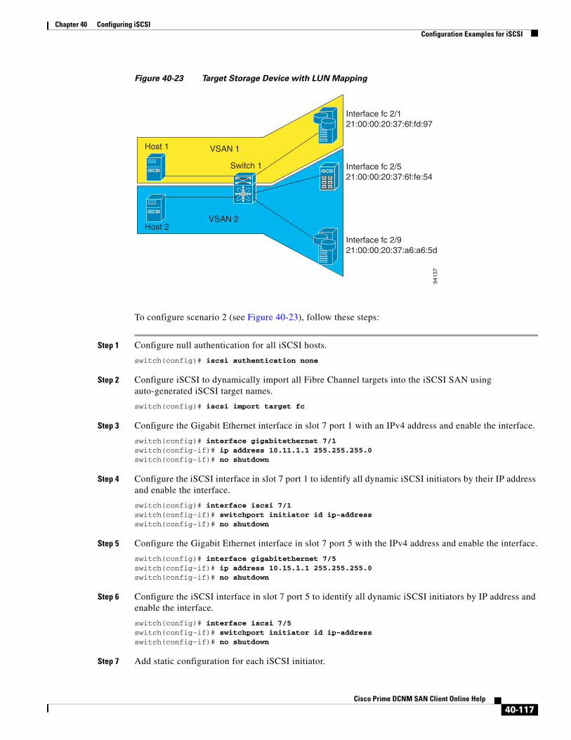
Chapter 40 Configuring iSCSIConfiguration Examples for iSCSI
Figure 40-23 Target Storage Device with LUN Mapping
To configure scenario 2 (see Figure 40-23), follow these steps:
Step 1 Configure null authentication for all iSCSI hosts.
switch(config)# iscsi authentication none
Step 2 Configure iSCSI to dynamically import all Fibre Channel targets into the iSCSI SAN using auto-generated iSCSI target names.
switch(config)# iscsi import target fc
Step 3 Configure the Gigabit Ethernet interface in slot 7 port 1 with an IPv4 address and enable the interface.
switch(config)# interface gigabitethernet 7/1 switch(config-if)# ip address 10.11.1.1 255.255.255.0 switch(config-if)# no shutdown
Step 4 Configure the iSCSI interface in slot 7 port 1 to identify all dynamic iSCSI initiators by their IP address and enable the interface.
switch(config)# interface iscsi 7/1switch(config-if)# switchport initiator id ip-address switch(config-if)# no shutdown
Step 5 Configure the Gigabit Ethernet interface in slot 7 port 5 with the IPv4 address and enable the interface.
switch(config)# interface gigabitethernet 7/5switch(config-if)# ip address 10.15.1.1 255.255.255.0switch(config-if)# no shutdown
Step 6 Configure the iSCSI interface in slot 7 port 5 to identify all dynamic iSCSI initiators by IP address and enable the interface.
switch(config)# interface iscsi 7/5switch(config-if)# switchport initiator id ip-address switch(config-if)# no shutdown
Step 7 Add static configuration for each iSCSI initiator.
iSCSI
iSCSI
iSCSI
Host 1
Host 2
Switch 1
VSAN 1
VSAN 2
9413
7
Interface fc 2/121:00:00:20:37:6f:fd:97
Interface fc 2/521:00:00:20:37:6f:fe:54
Interface fc 2/921:00:00:20:37:a6:a6:5d
40-117Cisco Prime DCNM SAN Client Online Help

Chapter 40 Configuring iSCSIConfiguration Examples for iSCSI
switch(config)# iscsi initiator name iqn.1987-05.com.cisco:01.e41695d16b1a <-----Host 2switch(config-iscsi-init)# static pWWN system-assign 1switch(config-iscsi-init)# static nWWN system-assign
switch(config)# iscsi initiator ip address 10.15.1.11 <-----------------------------------Host 1switch(config-iscsi-init)# static pwwn system-assigned 1switch(config-iscsi-init)# vsan 2
Note Host 1 is configured in VSAN 2.
Step 8 View the configured WWNs.
Note The WWNs are assigned by the system. The initiators are members of different VSANs.
switch# show iscsi initiator configured iSCSI Node name is iqn.1987-05.com.cisco:01.e41695d16b1a Member of vsans: 1 Node WWN is 20:03:00:0b:fd:44:68:c2 No. of PWWN: 1 Port WWN is 20:02:00:0b:fd:44:68:c2
iSCSI Node name is 10.15.1.11 Member of vsans: 2 No. of PWWN: 1 Port WWN is 20:06:00:0b:fd:44:68:c2
Step 9 Create a zone with host 1.
switch(config)# zone name iscsi-zone-1 vsan 1
Step 10 Add three members to the zone named iscsi-zone-1.
Note Fibre Channel storage for zone membership for the iSCSI initiator, either the iSCSI symbolic node name or the pWWN, can be used. In this case, the pWWN is persistent.
• The following command is based on the symbolic node name.
switch(config-zone)# member symbolic-nodename iqn.1987-05.com.cisco:01.e41695d16b1a
• The following command is based on the persistent pWWN assigned to the initiator. You can obtain the pWWN from the show iscsi initiator output.
switch(config-zone)# member pwwn 20:02:00:0b:fd:44:68:c2
Step 11 Create a zone with host 2 and two Fibre Channel targets.
Note If the host is in VSAN 2, the Fibre Channel targets and zone must also be in VSAN 2.
switch(config)# zone name iscsi-zone-2 vsan 2
Step 12 Activate the zone set in VSAN 2.
switch(config)# zoneset activate name iscsi-zoneset-v2 vsan 2 Zoneset activation initiated. check zone statusswitch# show zoneset active vsan 2zoneset name iscsi-zoneset-v2 vsan 2
40-118Cisco Prime DCNM SAN Client Online Help
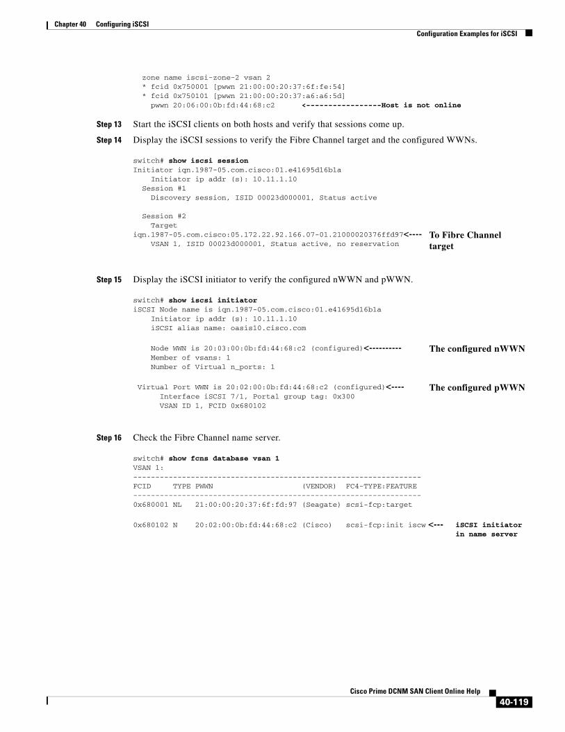
Chapter 40 Configuring iSCSIConfiguration Examples for iSCSI
zone name iscsi-zone-2 vsan 2 * fcid 0x750001 [pwwn 21:00:00:20:37:6f:fe:54] * fcid 0x750101 [pwwn 21:00:00:20:37:a6:a6:5d] pwwn 20:06:00:0b:fd:44:68:c2 <-----------------Host is not online
Step 13 Start the iSCSI clients on both hosts and verify that sessions come up.
Step 14 Display the iSCSI sessions to verify the Fibre Channel target and the configured WWNs.
Step 15 Display the iSCSI initiator to verify the configured nWWN and pWWN.
Step 16 Check the Fibre Channel name server.
switch# show iscsi session Initiator iqn.1987-05.com.cisco:01.e41695d16b1a Initiator ip addr (s): 10.11.1.10 Session #1 Discovery session, ISID 00023d000001, Status active
Session #2 Target iqn.1987-05.com.cisco:05.172.22.92.166.07-01.21000020376ffd97<---- VSAN 1, ISID 00023d000001, Status active, no reservation
To Fibre Channel target
switch# show iscsi initiator iSCSI Node name is iqn.1987-05.com.cisco:01.e41695d16b1a Initiator ip addr (s): 10.11.1.10 iSCSI alias name: oasis10.cisco.com
Node WWN is 20:03:00:0b:fd:44:68:c2 (configured)<---------- Member of vsans: 1 Number of Virtual n_ports: 1
The configured nWWN
Virtual Port WWN is 20:02:00:0b:fd:44:68:c2 (configured)<---- Interface iSCSI 7/1, Portal group tag: 0x300 VSAN ID 1, FCID 0x680102
The configured pWWN
switch# show fcns database vsan 1VSAN 1:-----------------------------------------------------------------FCID TYPE PWWN (VENDOR) FC4-TYPE:FEATURE-----------------------------------------------------------------0x680001 NL 21:00:00:20:37:6f:fd:97 (Seagate) scsi-fcp:target
0x680102 N 20:02:00:0b:fd:44:68:c2 (Cisco) scsi-fcp:init iscw <--- iSCSI initiator in name server
40-119Cisco Prime DCNM SAN Client Online Help

Chapter 40 Configuring iSCSIConfiguration Examples for iSCSI
Step 17 Verify the details of the iSCSI initiator's FC ID in the name server.
Step 18 Check the Fibre Channel name server.
Step 19 Verify the details of the iSCSI initiator's FC ID in the name server.
switch(config)# show fcns database fcid 0x680102 detail vsan 1------------------------VSAN:1 FCID:0x680102------------------------port-wwn (vendor) :20:02:00:0b:fd:44:68:c2 (Cisco) node-wwn :20:03:00:0b:fd:44:68:c2class :2,3node-ip-addr :10.11.1.10ipa :ff ff ff ff ff ff ff fffc4-types:fc4_features:scsi-fcp:init iscsi-gw symbolic-port-name :symbolic-node-name :iqn.1987-05.com.cisco:01.e41695d16b1aport-type :N port-ip-addr :0.0.0.0fabric-port-wwn :21:81:00:0b:fd:44:68:c0hard-addr :0x000000
Step 20 Verify that zoning has resolved the FC ID for the iSCSI client.
switch# show zoneset active vsan 1zoneset name iscsi-zoneset-v1 vsan 1 zone name iscsi-zone-1 vsan 1 * fcid 0x680001 [pwwn 21:00:00:20:37:6f:fd:97] * fcid 0x680102 [pwwn 20:02:00:0b:fd:44:68:c2]
switch(config)# show fcns database fcid 0x680102 detail vsan 1------------------------VSAN:1 FCID:0x680102------------------------port-wwn (vendor) :20:02:00:0b:fd:44:68:c2 (Cisco) node-wwn :20:03:00:0b:fd:44:68:c2class :2,3node-ip-addr :10.11.1.10ipa :ff ff ff ff ff ff ff fffc4-types:fc4_features:scsi-fcp:init iscsi-gw symbolic-port-name :symbolic-node-name :iqn.1987-05.com.cisco:01.e41695d16b1aport-type :N port-ip-addr :0.0.0.0fabric-port-wwn :21:81:00:0b:fd:44:68:c0 iSCSI alias name: oasis10.cisco.com
switch# show fcns database vsan 1VSAN 1:--------------------------------------------------------------FCID TYPE PWWN (VENDOR) FC4-TYPE:FEATURE-----------------------------------------------------------------0x680001 NL 21:00:00:20:37:6f:fd:97 (Seagate) scsi-fcp:target
0x680102 N 20:02:00:0b:fd:44:68:c2 (Cisco) scsi-fcp:init isc..w <----- iSCSI initiator in name server
40-120Cisco Prime DCNM SAN Client Online Help

Chapter 40 Configuring iSCSIConfiguration Examples for iSCSI
Step 21 Verify that the second initiator is connected to the two Fibre Channel targets in VSAN 2.
switch# show iscsi session initiator 10.15.1.11Initiator 10.15.1.11 Initiator name iqn.1987-05.com.cisco:01.25589167f74c Session #1 Target iqn.1987-05.com.cisco:05.172.22.92.166.07-05.21000020376ffe54 <-- VSAN 2, ISID 00023d000001, Status active, no reservation
Session to first target
Session #2 Target iqn.1987-05.com.cisco:05.172.22.92.166.07-05.2100002037a6a65d <-- VSAN 2, ISID 00023d000001, Status active, no reservation
Session to second target
switch# show iscsi initiator iSCSI Node name is 10.15.1.11 <--- Initiator ID is the IP address iSCSI Initiator name: iqn.1987-05.com.cisco:01.25589167f74c iSCSI alias name: oasis11.cisco.com
Node WWN is 20:04:00:0b:fd:44:68:c2 (dynamic) <------------------------ Member of vsans: 2 <--- vsan membership Number of Virtual n_ports: 1
Dynamic WWN as static WWN not assigned
Virtual Port WWN is 20:06:00:0b:fd:44:68:c2 (configured) <--------- Interface iSCSI 7/5, Portal group tag: 0x304 VSAN ID 2, FCID 0x750200
Static pWWN for the initiator
switch# show fcns database vsan 2VSAN 2:--------------------------------------------------------------------------FCID TYPE PWWN (VENDOR) FC4-TYPE:FEATURE--------------------------------------------------------------------------0x750001 NL 21:00:00:20:37:6f:fe:54 (Seagate) scsi-fcp:target 0x750101 NL 21:00:00:20:37:a6:a6:5d (Seagate) scsi-fcp:target
0x750200 N 20:06:00:0b:fd:44:68:c2 (Cisco) scsi-fcp:init isc..w <--Total number of entries = 3
iSCSI initiator entry in name server
switch# show fcns database fcid 0x750200 detail vsan 2------------------------VSAN:2 FCID:0x750200------------------------port-wwn (vendor) :20:06:00:0b:fd:44:68:c2 (Cisco) node-wwn :20:04:00:0b:fd:44:68:c2class :2,3node-ip-addr :10.15.1.11ipa :ff ff ff ff ff ff ff fffc4-types:fc4_features:scsi-fcp:init iscsi-gw symbolic-port-name :symbolic-node-name :10.15.1.11port-type :N port-ip-addr :0.0.0.0fabric-port-wwn :21:91:00:0b:fd:44:68:c0hard-addr :0x000000Total number of entries = 1
40-121Cisco Prime DCNM SAN Client Online Help
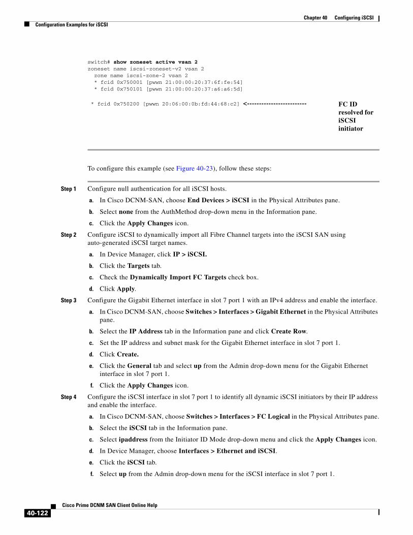
Chapter 40 Configuring iSCSIConfiguration Examples for iSCSI
To configure this example (see Figure 40-23), follow these steps:
Step 1 Configure null authentication for all iSCSI hosts.
a. In Cisco DCNM-SAN, choose End Devices > iSCSI in the Physical Attributes pane.
b. Select none from the AuthMethod drop-down menu in the Information pane.
c. Click the Apply Changes icon.
Step 2 Configure iSCSI to dynamically import all Fibre Channel targets into the iSCSI SAN using auto-generated iSCSI target names.
a. In Device Manager, click IP > iSCSI.
b. Click the Targets tab.
c. Check the Dynamically Import FC Targets check box.
d. Click Apply.
Step 3 Configure the Gigabit Ethernet interface in slot 7 port 1 with an IPv4 address and enable the interface.
a. In Cisco DCNM-SAN, choose Switches > Interfaces > Gigabit Ethernet in the Physical Attributes pane.
b. Select the IP Address tab in the Information pane and click Create Row.
c. Set the IP address and subnet mask for the Gigabit Ethernet interface in slot 7 port 1.
d. Click Create.
e. Click the General tab and select up from the Admin drop-down menu for the Gigabit Ethernet interface in slot 7 port 1.
f. Click the Apply Changes icon.
Step 4 Configure the iSCSI interface in slot 7 port 1 to identify all dynamic iSCSI initiators by their IP address and enable the interface.
a. In Cisco DCNM-SAN, choose Switches > Interfaces > FC Logical in the Physical Attributes pane.
b. Select the iSCSI tab in the Information pane.
c. Select ipaddress from the Initiator ID Mode drop-down menu and click the Apply Changes icon.
d. In Device Manager, choose Interfaces > Ethernet and iSCSI.
e. Click the iSCSI tab.
f. Select up from the Admin drop-down menu for the iSCSI interface in slot 7 port 1.
switch# show zoneset active vsan 2zoneset name iscsi-zoneset-v2 vsan 2 zone name iscsi-zone-2 vsan 2 * fcid 0x750001 [pwwn 21:00:00:20:37:6f:fe:54] * fcid 0x750101 [pwwn 21:00:00:20:37:a6:a6:5d]
* fcid 0x750200 [pwwn 20:06:00:0b:fd:44:68:c2] <------------------------- FC ID resolved for iSCSI initiator
40-122Cisco Prime DCNM SAN Client Online Help
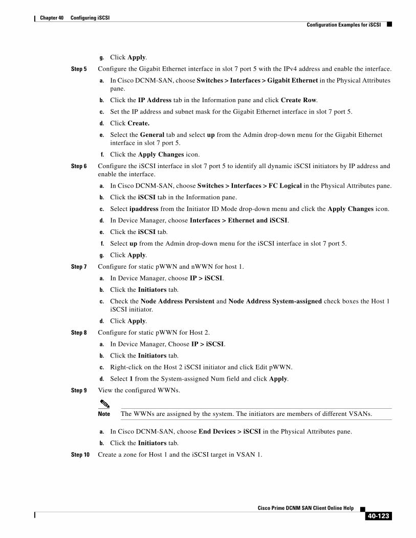
Chapter 40 Configuring iSCSIConfiguration Examples for iSCSI
g. Click Apply.
Step 5 Configure the Gigabit Ethernet interface in slot 7 port 5 with the IPv4 address and enable the interface.
a. In Cisco DCNM-SAN, choose Switches > Interfaces > Gigabit Ethernet in the Physical Attributes pane.
b. Click the IP Address tab in the Information pane and click Create Row.
c. Set the IP address and subnet mask for the Gigabit Ethernet interface in slot 7 port 5.
d. Click Create.
e. Select the General tab and select up from the Admin drop-down menu for the Gigabit Ethernet interface in slot 7 port 5.
f. Click the Apply Changes icon.
Step 6 Configure the iSCSI interface in slot 7 port 5 to identify all dynamic iSCSI initiators by IP address and enable the interface.
a. In Cisco DCNM-SAN, choose Switches > Interfaces > FC Logical in the Physical Attributes pane.
b. Click the iSCSI tab in the Information pane.
c. Select ipaddress from the Initiator ID Mode drop-down menu and click the Apply Changes icon.
d. In Device Manager, choose Interfaces > Ethernet and iSCSI.
e. Click the iSCSI tab.
f. Select up from the Admin drop-down menu for the iSCSI interface in slot 7 port 5.
g. Click Apply.
Step 7 Configure for static pWWN and nWWN for host 1.
a. In Device Manager, choose IP > iSCSI.
b. Click the Initiators tab.
c. Check the Node Address Persistent and Node Address System-assigned check boxes the Host 1 iSCSI initiator.
d. Click Apply.
Step 8 Configure for static pWWN for Host 2.
a. In Device Manager, Choose IP > iSCSI.
b. Click the Initiators tab.
c. Right-click on the Host 2 iSCSI initiator and click Edit pWWN.
d. Select 1 from the System-assigned Num field and click Apply.
Step 9 View the configured WWNs.
Note The WWNs are assigned by the system. The initiators are members of different VSANs.
a. In Cisco DCNM-SAN, choose End Devices > iSCSI in the Physical Attributes pane.
b. Click the Initiators tab.
Step 10 Create a zone for Host 1 and the iSCSI target in VSAN 1.
40-123Cisco Prime DCNM SAN Client Online Help
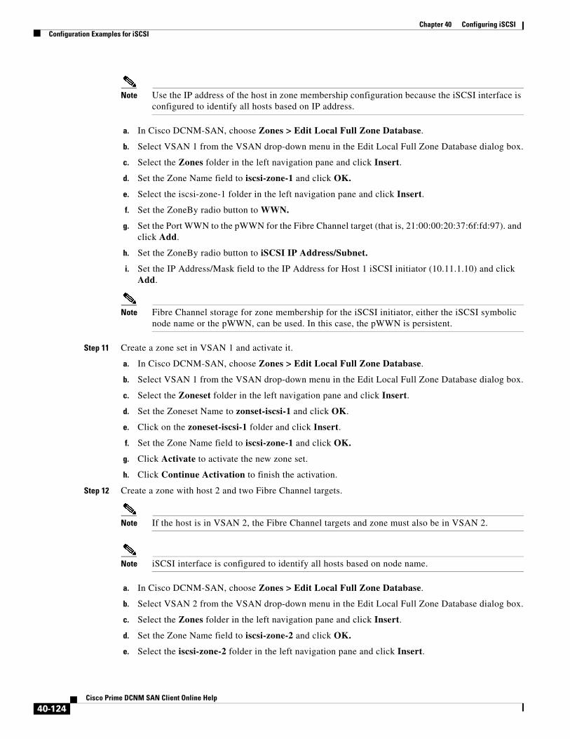
Chapter 40 Configuring iSCSIConfiguration Examples for iSCSI
Note Use the IP address of the host in zone membership configuration because the iSCSI interface is configured to identify all hosts based on IP address.
a. In Cisco DCNM-SAN, choose Zones > Edit Local Full Zone Database.
b. Select VSAN 1 from the VSAN drop-down menu in the Edit Local Full Zone Database dialog box.
c. Select the Zones folder in the left navigation pane and click Insert.
d. Set the Zone Name field to iscsi-zone-1 and click OK.
e. Select the iscsi-zone-1 folder in the left navigation pane and click Insert.
f. Set the ZoneBy radio button to WWN.
g. Set the Port WWN to the pWWN for the Fibre Channel target (that is, 21:00:00:20:37:6f:fd:97). and click Add.
h. Set the ZoneBy radio button to iSCSI IP Address/Subnet.
i. Set the IP Address/Mask field to the IP Address for Host 1 iSCSI initiator (10.11.1.10) and click Add.
Note Fibre Channel storage for zone membership for the iSCSI initiator, either the iSCSI symbolic node name or the pWWN, can be used. In this case, the pWWN is persistent.
Step 11 Create a zone set in VSAN 1 and activate it.
a. In Cisco DCNM-SAN, choose Zones > Edit Local Full Zone Database.
b. Select VSAN 1 from the VSAN drop-down menu in the Edit Local Full Zone Database dialog box.
c. Select the Zoneset folder in the left navigation pane and click Insert.
d. Set the Zoneset Name to zonset-iscsi-1 and click OK.
e. Click on the zoneset-iscsi-1 folder and click Insert.
f. Set the Zone Name field to iscsi-zone-1 and click OK.
g. Click Activate to activate the new zone set.
h. Click Continue Activation to finish the activation.
Step 12 Create a zone with host 2 and two Fibre Channel targets.
Note If the host is in VSAN 2, the Fibre Channel targets and zone must also be in VSAN 2.
Note iSCSI interface is configured to identify all hosts based on node name.
a. In Cisco DCNM-SAN, choose Zones > Edit Local Full Zone Database.
b. Select VSAN 2 from the VSAN drop-down menu in the Edit Local Full Zone Database dialog box.
c. Select the Zones folder in the left navigation pane and click Insert.
d. Set the Zone Name field to iscsi-zone-2 and click OK.
e. Select the iscsi-zone-2 folder in the left navigation pane and click Insert.
40-124Cisco Prime DCNM SAN Client Online Help

Chapter 40 Configuring iSCSIField Descriptions for iSCSI
f. Set the ZoneBy radio button toWWN.
g. Set the Port WWN to the pWWN for one of the Fibre Channel targets (for example, 21:00:00:20:37:6f:fe:5) and click Add.
h. Set the Port WWN to the pWWN for another of the Fibre Channel targets (for example, 21:00:00:20:37:a6:a6:5d) and click Add.
i. Set the ZoneBy radio button to iSCSI IP Address/Subnet.
j. Set the IP Address/Mask field to the IP Address for Host 2 iSCSI initiator (10.15.1.11) and click Add.
Step 13 Create a zone set in VSAN 2 and activate it.
a. In Cisco DCNM-SAN, choose Zones > Edit Local Full Zone Database.
b. Select VSAN 2 from the VSAN drop-down menu in the Edit Local Full Zone Database dialog box.
c. Select the Zoneset folder in the left navigation pane and click Insert.
d. Set the Zoneset Name to zonset-iscsi-2 and click OK.
e. Click on the zoneset-iscsi-2 folder and click Insert.
f. Set the Zone Name field to iscsi-zone-2 and click OK.
g. Click Activate to activate the new zone set.
h. Click Continue Activation to finish the activation.
Step 14 Start the iSCSI clients on both hosts.
Step 15 Show all the iSCSI sessions.
a. In Device Manager, choose Interface > Monitor > Ethernet and select the iSCSI connections tab to show all the iSCSI sessions.
b. In Device Manager, choose IP > iSCSI and select the Session Initiators tab.
c. Click Details.
Step 16 In Cisco DCNM- SAN, choose End Devices > iSCSI in the Physical Attributes pane to verify the details of the two iSCSI initiators.
Step 17 In Cisco DCNM-SAN, choose Zones > Edit Local Full Zone Database to view the active zone set. The iSCSI initiators' FC IDs are resolved.
Step 18 In Device Manager, choose FC > Name Server. The Fibre Channel name server shows the virtual N ports created for the iSCSI hosts.
Step 19 In Device Manager, Choose FC > Name Server.
Step 20 Click the Advanced tab. Verify the detailed output of the iSCSI initiator nodes in the Fibre Channel name server.
Field Descriptions for iSCSIThe following are the field descriptions for iSCSI.
40-125Cisco Prime DCNM SAN Client Online Help

Chapter 40 Configuring iSCSIField Descriptions for iSCSI
Ethernet Interfaces iSCSI
Ethernet Interfaces iSCSI TCP
Field Description
Description An alias name for the interface as specified by a network manager.
Speed Operational speed.
PhysAddress The interface's WWN.
Admin The desired state of the interface.
Oper The current operational state of the interface.
LastChange When the interface entered its current operational state. If the current state was entered prior to the last re-initialization of the local network management subsystem, then this value contains a N/A value.
PortVSAN The VSAN that the interface belongs to.
ForwardingMode Use Store and Forward if the HBA has problems with passthrough.
Initiator ID Mode How the initiator is identified on this interface, either by its iSCSI name (name) or by its IP address (ipaddress).
Enable The intiator proxy mode for this interface. If true, then all the initiators coming on this interface would use the intiator configuration provided by this interface. The initiator configuration include port WWN and node WWN.
Assignment How the initiator proxy mode FC addresses are assigned. If auto, then the FC addresses are automatically assigned. If it is manual, then they have to be manually configured.
Port WWN The Port FC address used by the intiators on this interface when the intiator proxy mode is on.
Node WWN The Node FC address used by the initiators on this interface when the initiator proxy mode is on.
Field Description
Local Port Local interface TCP port.
SACK Indicates if the Selective Acknowledgement (SACK) option is enabled or not.
KeepAlive The TCP keepalive timeout for this iSCSI interface. If the value is 0, the keepalive timeout feature is disabled.
MinTimeout The TCP minimum retransmit time.
Max The TCP maximum retransmissions.
SendBufferSize The TCP send buffer size.
MinBandwidth The TCP minimum bandwidth.
MaxBandwidth The TCP maximum bandwidth.
40-126Cisco Prime DCNM SAN Client Online Help
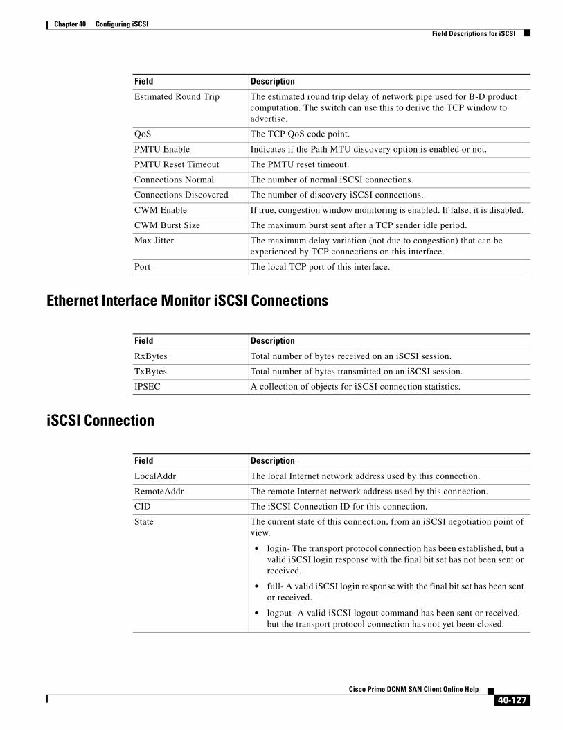
Chapter 40 Configuring iSCSIField Descriptions for iSCSI
Ethernet Interface Monitor iSCSI Connections
iSCSI Connection
Estimated Round Trip The estimated round trip delay of network pipe used for B-D product computation. The switch can use this to derive the TCP window to advertise.
QoS The TCP QoS code point.
PMTU Enable Indicates if the Path MTU discovery option is enabled or not.
PMTU Reset Timeout The PMTU reset timeout.
Connections Normal The number of normal iSCSI connections.
Connections Discovered The number of discovery iSCSI connections.
CWM Enable If true, congestion window monitoring is enabled. If false, it is disabled.
CWM Burst Size The maximum burst sent after a TCP sender idle period.
Max Jitter The maximum delay variation (not due to congestion) that can be experienced by TCP connections on this interface.
Port The local TCP port of this interface.
Field Description
RxBytes Total number of bytes received on an iSCSI session.
TxBytes Total number of bytes transmitted on an iSCSI session.
IPSEC A collection of objects for iSCSI connection statistics.
Field Description
LocalAddr The local Internet network address used by this connection.
RemoteAddr The remote Internet network address used by this connection.
CID The iSCSI Connection ID for this connection.
State The current state of this connection, from an iSCSI negotiation point of view.
• login- The transport protocol connection has been established, but a valid iSCSI login response with the final bit set has not been sent or received.
• full- A valid iSCSI login response with the final bit set has been sent or received.
• logout- A valid iSCSI logout command has been sent or received, but the transport protocol connection has not yet been closed.
Field Description
40-127Cisco Prime DCNM SAN Client Online Help

Chapter 40 Configuring iSCSIField Descriptions for iSCSI
iSCSI Initiators
MaxRecvDSLen The maximum data payload size supported for command or data PDUs in use within this connection. Note that the size of reported in bytes even though the negotiation is in 512 k blocks.
SendMarker Indicates whether or not this connection is inserting markers in its outgoing data stream.
HeaderDigest The iSCSI header digest scheme in use within this connection.
DataDigest The iSCSI data digest scheme in use within this connection.
Field Description
Name or IP Address A character string that is a globally unique identifier for the node represented by this entry.
VSAN Membership The list of configured VSANs the node represented by this entry can access.
Dynamic If true, then the node represented by this entry is automatically discovered.
Initiator Type Indicates whether the node is a host that participates in iSCSI load balancing.
Persistent Node WWN If true, then the same FC address is assigned to the node if it were to be represented again in the FC domain with the same node name. Note that the node FC address is either automatically assigned or manually configured.
SystemAssigned Node WWNN
If true, the FC address is automatically assigned to this node. If false, then the FC address has to be configured manually.
Node WWN The persistent FC address of the node.
Persistent Port WWN If true, then the same FC address is assigned to the ports of the node if it were to be represented again in the FC domain with the same node name.
Port WWN All the FC port addresses associated with this node.
AuthUser This is the only CHAP user name that the initiator is allowed to log in with.
Target UserName (Optional) The user name to be used for login. If you do not supply a username, the global user name is used.
Target Password (Optional) The password to be used for login. If you do not supply a password, the global password is used.
Load Metric A configured load metric of this iSCSI initiator for the purpose of iSCSI load balancing.
Auto Zone Name The zone name that is used when the system creates automatic zone for this initiator's specific list of targets.
Field Description
40-128Cisco Prime DCNM SAN Client Online Help
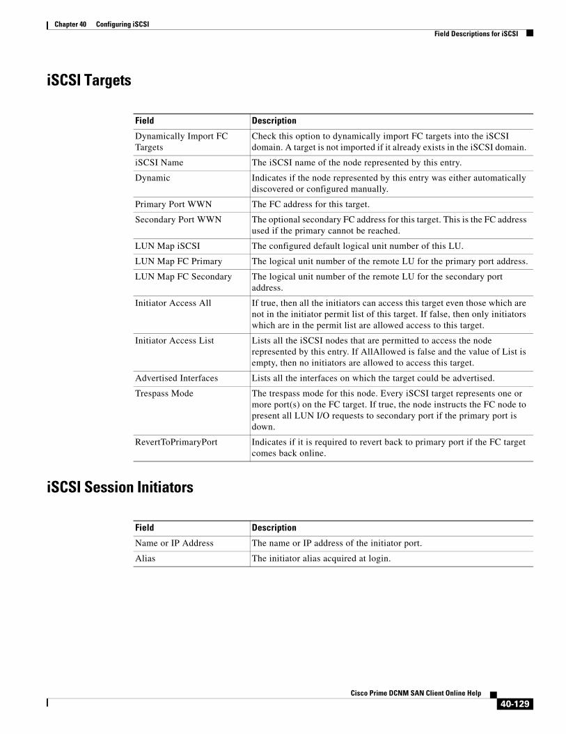
Chapter 40 Configuring iSCSIField Descriptions for iSCSI
iSCSI Targets
iSCSI Session Initiators
Field Description
Dynamically Import FC Targets
Check this option to dynamically import FC targets into the iSCSI domain. A target is not imported if it already exists in the iSCSI domain.
iSCSI Name The iSCSI name of the node represented by this entry.
Dynamic Indicates if the node represented by this entry was either automatically discovered or configured manually.
Primary Port WWN The FC address for this target.
Secondary Port WWN The optional secondary FC address for this target. This is the FC address used if the primary cannot be reached.
LUN Map iSCSI The configured default logical unit number of this LU.
LUN Map FC Primary The logical unit number of the remote LU for the primary port address.
LUN Map FC Secondary The logical unit number of the remote LU for the secondary port address.
Initiator Access All If true, then all the initiators can access this target even those which are not in the initiator permit list of this target. If false, then only initiators which are in the permit list are allowed access to this target.
Initiator Access List Lists all the iSCSI nodes that are permitted to access the node represented by this entry. If AllAllowed is false and the value of List is empty, then no initiators are allowed to access this target.
Advertised Interfaces Lists all the interfaces on which the target could be advertised.
Trespass Mode The trespass mode for this node. Every iSCSI target represents one or more port(s) on the FC target. If true, the node instructs the FC node to present all LUN I/O requests to secondary port if the primary port is down.
RevertToPrimaryPort Indicates if it is required to revert back to primary port if the FC target comes back online.
Field Description
Name or IP Address The name or IP address of the initiator port.
Alias The initiator alias acquired at login.
40-129Cisco Prime DCNM SAN Client Online Help
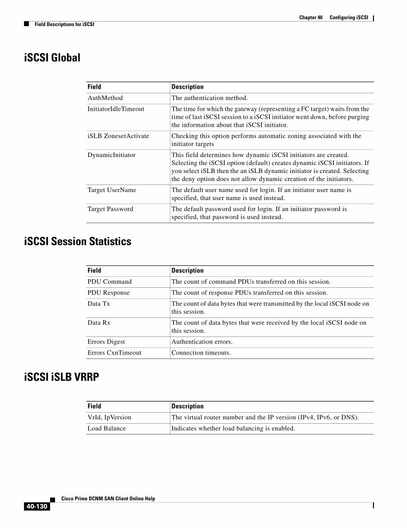
Chapter 40 Configuring iSCSIField Descriptions for iSCSI
iSCSI Global
iSCSI Session Statistics
iSCSI iSLB VRRP
Field Description
AuthMethod The authentication method.
InitiatorIdleTimeout The time for which the gateway (representing a FC target) waits from the time of last iSCSI session to a iSCSI initiator went down, before purging the information about that iSCSI initiator.
iSLB ZonesetActivate Checking this option performs automatic zoning associated with the initiator targets
DynamicInitiator This field determines how dynamic iSCSI initiators are created. Selecting the iSCSI option (default) creates dynamic iSCSI initiators. If you select iSLB then the an iSLB dynamic initiator is created. Selecting the deny option does not allow dynamic creation of the initiators.
Target UserName The default user name used for login. If an initiator user name is specified, that user name is used instead.
Target Password The default password used for login. If an initiator password is specified, that password is used instead.
Field Description
PDU Command The count of command PDUs transferred on this session.
PDU Response The count of response PDUs transferred on this session.
Data Tx The count of data bytes that were transmitted by the local iSCSI node on this session.
Data Rx The count of data bytes that were received by the local iSCSI node on this session.
Errors Digest Authentication errors.
Errors CxnTimeout Connection timeouts.
Field Description
VrId, IpVersion The virtual router number and the IP version (IPv4, IPv6, or DNS).
Load Balance Indicates whether load balancing is enabled.
40-130Cisco Prime DCNM SAN Client Online Help

Chapter 40 Configuring iSCSIField Descriptions for iSCSI
iSCSI Initiator Access
iSCSI Initiator PWWN
iSCSI Sessions
iSCSI Sessions Detail
Field Description
Initiator Name The iSCSI node name.
Field Description
Port WWN The FC address for this entry.
Field Description
Type Type of iSCSI session:
• normal—session is a normal iSCSI session
• discovery—session is being used only for discovery.
TargetName If Direction is Outbound, this will contain the name of the remote target.
Vsan ID The VSAN to which this session belongs to.
ISID The initiator-defined portion of the iSCSI session ID.
TSIH The target-defined identification handle for this session.
Field Description
ConnectionNumber The number of transport protocol connections that currently belong to this session.
ImmediateData Whether the initiator and target have agreed to support immediate data on this session.
Initial If true, the initiator must wait for a Ready-To-Transfer before sending to the target. If false, the initiator may send data immediately, within limits set by FirstBurstSize and the expected data transfer length of the request.
MaxOutstanding The maximum number of outstanding Ready-To-Transfers per task within this session.
First The maximum length supported for unsolicited data sent within this session.
40-131Cisco Prime DCNM SAN Client Online Help
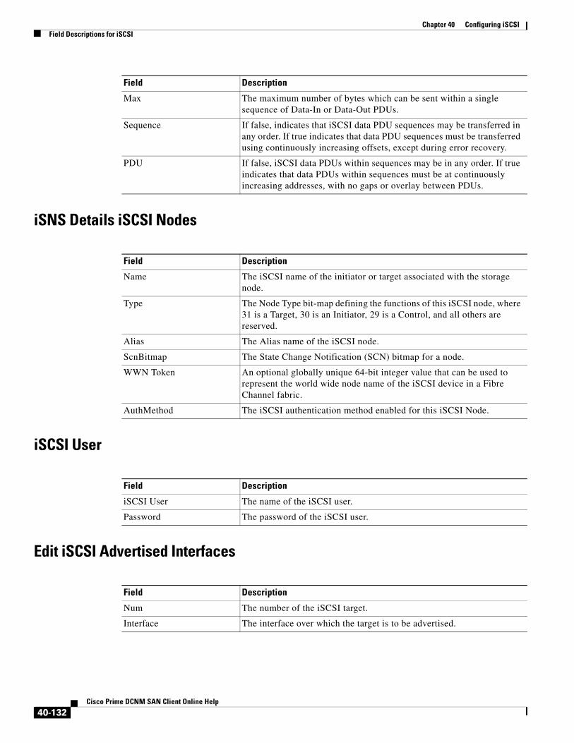
Chapter 40 Configuring iSCSIField Descriptions for iSCSI
iSNS Details iSCSI Nodes
iSCSI User
Edit iSCSI Advertised Interfaces
Max The maximum number of bytes which can be sent within a single sequence of Data-In or Data-Out PDUs.
Sequence If false, indicates that iSCSI data PDU sequences may be transferred in any order. If true indicates that data PDU sequences must be transferred using continuously increasing offsets, except during error recovery.
PDU If false, iSCSI data PDUs within sequences may be in any order. If true indicates that data PDUs within sequences must be at continuously increasing addresses, with no gaps or overlay between PDUs.
Field Description
Name The iSCSI name of the initiator or target associated with the storage node.
Type The Node Type bit-map defining the functions of this iSCSI node, where 31 is a Target, 30 is an Initiator, 29 is a Control, and all others are reserved.
Alias The Alias name of the iSCSI node.
ScnBitmap The State Change Notification (SCN) bitmap for a node.
WWN Token An optional globally unique 64-bit integer value that can be used to represent the world wide node name of the iSCSI device in a Fibre Channel fabric.
AuthMethod The iSCSI authentication method enabled for this iSCSI Node.
Field Description
Field Description
iSCSI User The name of the iSCSI user.
Password The password of the iSCSI user.
Field Description
Num The number of the iSCSI target.
Interface The interface over which the target is to be advertised.
40-132Cisco Prime DCNM SAN Client Online Help

Chapter 40 Configuring iSCSIAdditional References
Additional ReferencesFor additional information related to implementing FCIPs, see the following section:
• Related Document section, page 40-133
• Standards section, page 40-133
• RFCs section, page 40-133
• MIBs section, page 40-133
Related Document
Standards
RFCs
MIBs
Related Topic Document Title
Cisco MDS 9000 Family Command Reference Cisco MDS 9000 Family Command Reference, Release 5.0(1a)
Standard Title
No new or modified standards are supported by this feature, and support for existing standards has not been modified by this feature.
–
RFC Title
No new or modified RFCs are supported by this feature, and support for existing RFCs has not been modified.
–
MIBs MIBs Link
• CISCO-ISCI-GW-MIB
• CISCO-ISCSI-MIB
To locate and download MIBs, go to the following URL:
http://www.cisco.com/dc-os/mibs
40-133Cisco Prime DCNM SAN Client Online Help

Chapter 40 Configuring iSCSIAdditional References
40-134Cisco Prime DCNM SAN Client Online Help


![[MS-ISTM]: iSCSI Software Target Management Protocol](https://static.fdocuments.us/doc/165x107/586a39cf1a28ab3d018bf3b7/ms-istm-iscsi-software-target-management-protocol.jpg)

![[MS-ISTD]: iSCSI Software Target Discovery ProtocolMS-ISTD].pdf · iSCSI Software Target Discovery Protocol ... [MS-ISTD]: iSCSI Software Target Discovery Protocol ... The component](https://static.fdocuments.us/doc/165x107/5aa8c7067f8b9a9a188c0144/ms-istd-iscsi-software-target-discovery-protocol-ms-istdpdfiscsi-software-target.jpg)