The Internet, IPv4 and IPv6 - Massey University€¦ · The Internet, IPv4 and IPv6 ... – Accept...
89
The Internet, IPv4 and IPv6 ICT Technical Update Module
Transcript of The Internet, IPv4 and IPv6 - Massey University€¦ · The Internet, IPv4 and IPv6 ... – Accept...
The Internet, IPv4 and IPv6
ICT Technical Update Module
Post Graduate Certificate in Professional Development Slide 2
Presentation Outline• Internetworking in practice:
– How are networks interconnected?
– What devices are used?
– What is encapsulation and why is it necessary?
– How is addressing performed in the Internet?
– What is the Internet Protocol v4?
– How will the Next Generation Network use IPv6?

Post Graduate Certificate in Professional Development Slide 3
Objectives• You will be able to explain the various terms used for
internetworking• You will be able to explain the concepts of fragmentation
and reassembly as they apply to Internet packets• You will be able to explain why packets can be received out
of order and the mechanisms for preventing this• You will be able to perform subnet masking tasks with
Internet addresses• You will be able to identify the various special addresses
and their purposes• You will be able to compare and contrast the two versions
of the Internet Protocol.
Post Graduate Certificate in Professional Development Slide 4
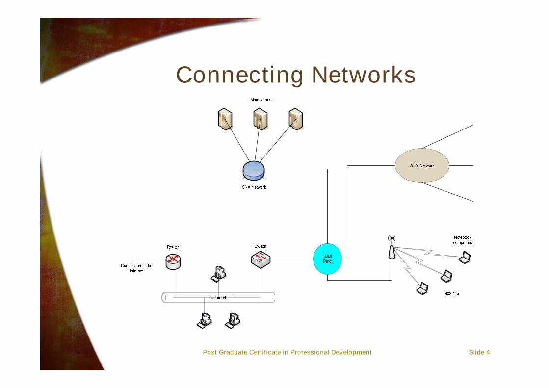
Connecting Networks
Post Graduate Certificate in Professional Development Slide 5
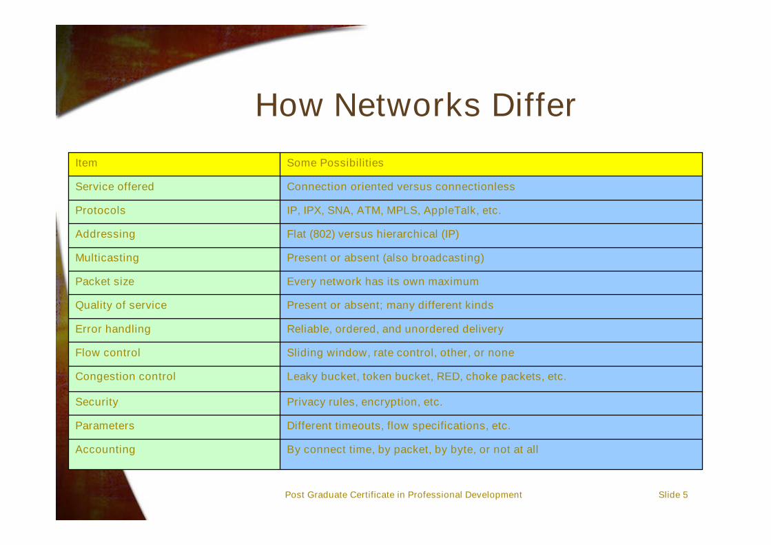
How Networks Differ
By connect time, by packet, by byte, or not at allAccounting
Different timeouts, flow specifications, etc.Parameters
Privacy rules, encryption, etc.Security
Leaky bucket, token bucket, RED, choke packets, etc.Congestion control
Sliding window, rate control, other, or noneFlow control
Reliable, ordered, and unordered deliveryError handling
Present or absent; many different kindsQuality of service
Every network has its own maximumPacket size
Present or absent (also broadcasting)Multicasting
Flat (802) versus hierarchical (IP)Addressing
IP, IPX, SNA, ATM, MPLS, AppleTalk, etc.Protocols
Connection oriented versus connectionlessService offered
Some PossibilitiesItem
Post Graduate Certificate in Professional Development Slide 6
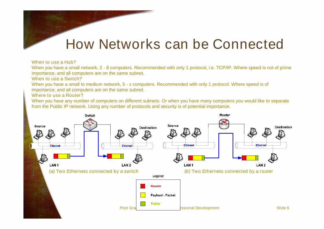
How Networks can be Connected
(a) Two Ethernets connected by a switch (b) Two Ethernets connected by a router
When to use a Hub?When you have a small network, 2 - 8 computers. Recommended with only 1 protocol, i.e. TCP/IP. Where speed is not of primeimportance, and all computers are on the same subnet.When to use a Switch?When you have a small to medium network, 5 - x computers. Recommended with only 1 protocol. Where speed is ofimportance, and all computers are on the same subnet.Where to use a Router?When you have any number of computers on different subnets. Or when you have many computers you would like to separatefrom the Public IP network. Using any number of protocols and security is of potential importance.
Post Graduate Certificate in Professional Development Slide 7
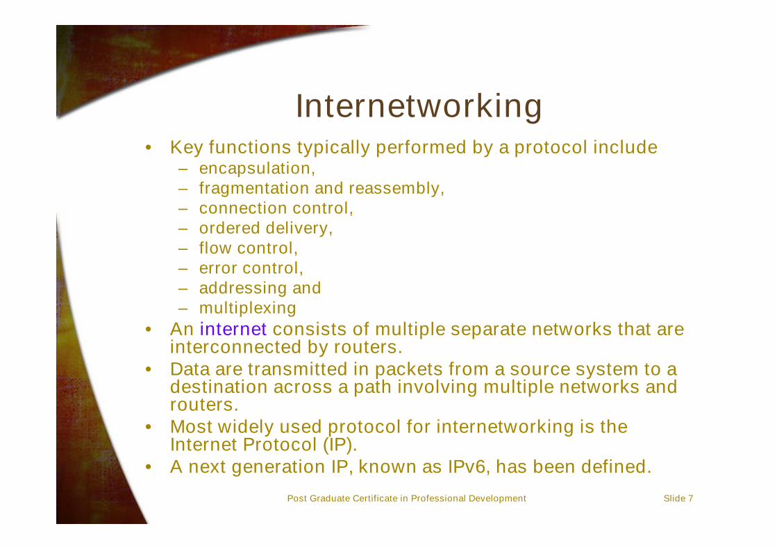
Internetworking• Key functions typically performed by a protocol include
– encapsulation,– fragmentation and reassembly,– connection control,– ordered delivery,– flow control,– error control,– addressing and– multiplexing
• An internet consists of multiple separate networks that areinterconnected by routers.
• Data are transmitted in packets from a source system to adestination across a path involving multiple networks androuters.
• Most widely used protocol for internetworking is theInternet Protocol (IP).
• A next generation IP, known as IPv6, has been defined.

Post Graduate Certificate in Professional Development Slide 8
Internetworking Terms - 1• Communications Network
– Facility that provides data transfer service
• An internet– Collection of communications networks interconnected
by bridges and/or routers
• The Internet (note the upper case I)– The global collection of thousands of individual
machines and networks
• Intranet– Corporate internet operating within the organization-
Uses Internet (TCP/IP and http) technology to deliverdocuments and
Post Graduate Certificate in Professional Development Slide 9
Internetworking Terms - 2• End System (ES)
– Device attached to one of the networks of an internet– Supports end-user applications or services
• Intermediate System (IS)– Device used to connect two networks– Permits communication between end systems attached to
different networks• Bridge
– Is used to connect two LANs using similar LAN protocols– Accept frames, examine the MAC addresses, and forward the
frames to different networks while doing minor protocoltranslation in the process
– OSI layer 2 (Data Link)• Router
– Connects two (possibly dissimilar) networks
Post Graduate Certificate in Professional Development Slide 10
Protocol Functions• Encapsulation• Fragmentation and reassembly• Connection control• Ordered delivery• Flow control• Error control• Addressing• Multiplexing• Transmission services

Post Graduate Certificate in Professional Development Slide 11
Encapsulation• Data, accepted or generated by entity, is usually
transferred in blocks, called Protocol Data Units(PDUs)– Each PDU contains data and control information– Some PDUs contain only control information
• Three categories of control– Address
• Of sender and/or receiver– Error-detecting code
• E.g. frame check sequence– Protocol control
• Additional information to implement protocol functions
• Addition of control information to data is referredto as encapsulation.
Post Graduate Certificate in Professional Development Slide 12
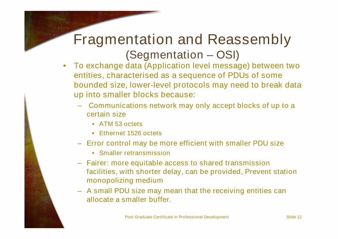
Fragmentation and Reassembly(Segmentation – OSI)
• To exchange data (Application level message) between twoentities, characterised as a sequence of PDUs of somebounded size, lower-level protocols may need to break dataup into smaller blocks because:– Communications network may only accept blocks of up to a
certain size• ATM 53 octets• Ethernet 1526 octets
– Error control may be more efficient with smaller PDU size• Smaller retransmission
– Fairer: more equitable access to shared transmissionfacilities, with shorter delay, can be provided, Prevent stationmonopolizing medium
– A small PDU size may mean that the receiving entities canallocate a smaller buffer.

Post Graduate Certificate in Professional Development Slide 13
Reassembly• Segmented data must be reassembled into
messages• More complex if PDUs are out of order….• General process is illustrated below:
Application Data PDU
Transportheader
Transportheader
Networkheader
Networkheader
Transportprotocol data units
Networkprotocol data units
(packets)

Post Graduate Certificate in Professional Development Slide 14
Connection Control• Connectionless data transfer
– Each PDU treated independently– E.g. datagram
• Connection-oriented data transfer– E.g. virtual circuit
• Connection-oriented preferred (even required) forlengthy exchange of data
• Three phases occur– Connection establishment– Data transfer– Connection termination– There may be interrupt and recovery phases to handle
errors

Post Graduate Certificate in Professional Development Slide 15
Phases of Connection - OrientedTransfer
ProtocolEntity
Connection request
Connection accept
Data
Acknowledgement
Terminate-connection request
Terminate-connection accept
ProtocolEntity
Tim
e

Post Graduate Certificate in Professional Development Slide 16
Ordered Delivery• PDUs may arrive out of order
– Caused by different paths through the network
• In order to maintain PDUs in order, PDUs need tobe sequentially numbered
Post Graduate Certificate in Professional Development Slide 17
Flow Control• Performed by receiving entity to limit the amount
or rate of data being sent• Stop and wait protocol, sliding window
techniques are both example of this approach.

Post Graduate Certificate in Professional Development Slide 18
Error Control• Guard against loss or damage• Error detection and retransmission
– Sender inserts error-detecting code in PDU– Receiver checks code on incoming PDU– If error, discard– If transmitter doesn't get an acknowledgment in a
reasonable time, retransmit
• Error- correction code• Error control is performed at various layers of the
protocol stack– Between station and network– Inside network
Post Graduate Certificate in Professional Development Slide 19
Introduction to the Internet• Interconnects tens of millions of computers
around the world and is continuing to grow veryrapidly!
• Consistently doubled in size from 1969 onwards• Started as a research project involving about 4
computers in 1969.• Users can:
– Exchange electronic mail– Read and post to electronic news bulletins– Access files on remote computers anywhere in the
world– Publish information to other Internet users
Post Graduate Certificate in Professional Development Slide 20
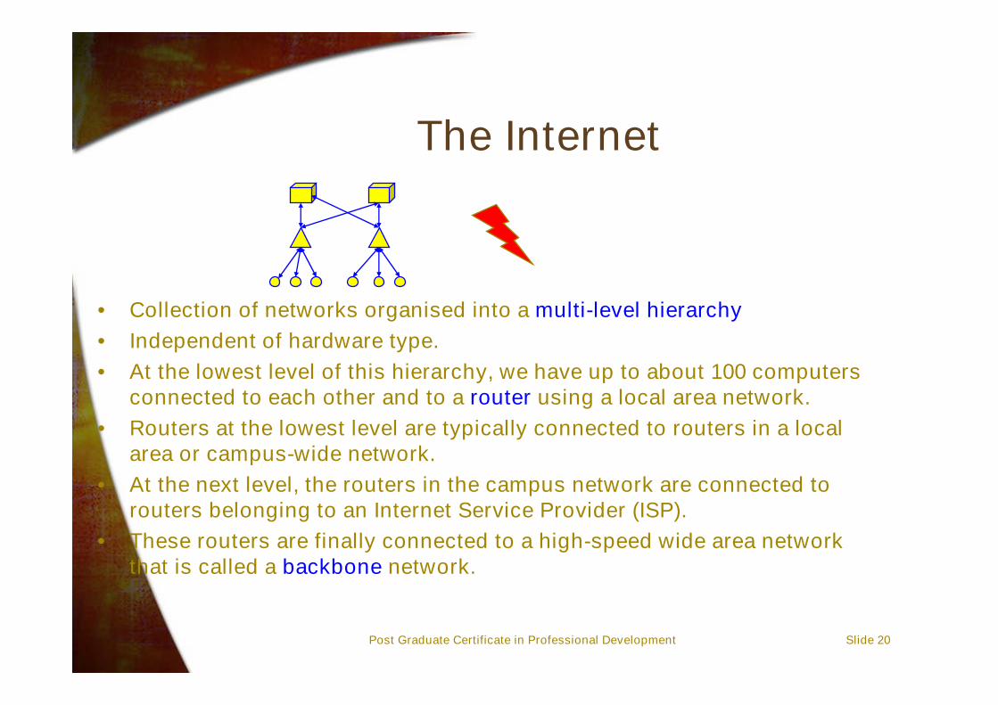
The Internet
• Collection of networks organised into a multi-level hierarchy• Independent of hardware type.• At the lowest level of this hierarchy, we have up to about 100 computers
connected to each other and to a router using a local area network.• Routers at the lowest level are typically connected to routers in a local
area or campus-wide network.• At the next level, the routers in the campus network are connected to
routers belonging to an Internet Service Provider (ISP).• These routers are finally connected to a high-speed wide area network
that is called a backbone network.

Post Graduate Certificate in Professional Development Slide 21
3 Concepts Underpinning the Internet• The key concepts that underpin the Internet are:
– Addressing• People need to be able to send data to you through the
network. This requires a method for identifying you as theintended recipient! Hence the need to have an addresswhere you can be reached.
– Routing• There needs to be a methodology to send messages
around the network based on prevailing networkconditions, speeds of the links, availability of capacity etc.
– Internet Protocol• All the devices in the network need to speak the same
“language” and this is a protocol for ensuring that themessages can be delivered correctly to their intendedaddressee.
Note:Note: Each of these concepts is designed to be scalable to largenetworks

Post Graduate Certificate in Professional Development Slide 22
Internet Technology
• Two principal ideas support Internettechnology:
– Packets– Store and forward transmission
InformationInformation
PacketsPackets
Illustration of the Store and Forward technique:
Packetising of a message:
StartStart EndEnd
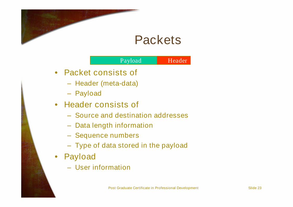
Post Graduate Certificate in Professional Development Slide 23
Packets
• Packet consists of– Header (meta-data)– Payload
• Header consists of– Source and destination addresses– Data length information– Sequence numbers– Type of data stored in the payload
• Payload– User information
Payload Header

Post Graduate Certificate in Professional Development Slide 24
Problems with Packets• Packets are quite efficient as a means of transferring
data, but applications such as voice or other real-timeservices may experience some problems.
• Consider digitising voice at the rate of 8000 samplesper second. Suppose that each sample is just 1 byte.– How long will it take to fill a 500-byte packet?– If interactive voice can only tolerate 100msec of delay,
what fraction of the 100msec is actually spent onpacketisation?
•• Answers:Answers:– Each sample corresponds to 1/8000 seconds so 500
samples take 500/8000 = 62.5msec.– As a fraction of 100msec we can see that 62.5% of the
delay budget is taken up with packetising the voice!!!
Post Graduate Certificate in Professional Development Slide 25
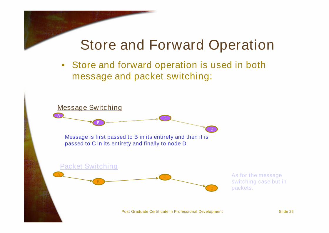
Store and Forward Operation• Store and forward operation is used in both
message and packet switching:
Message SwitchingA
BC
D
Message is first passed to B in its entirety and then it ispassed to C in its entirety and finally to node D.
Packet SwitchingA
BC
D
As for the messageswitching case but inpackets.

Post Graduate Certificate in Professional Development Slide 26
Problems with Store and ForwardOperation
• Store and forward networks are less expensive to operatethan circuit switched networks, but users do find someproblems with store and forward operation:
– Users cannot control how long their packets will take totraverse the network - how long will packets be delayed?
– By definition, packets are stored at the network nodes. Bufferspace can be expensive.
– Buffers are finite in size and so there is a chance that it will beinsufficient if many users send data via the same node -leading to loss of packets if the buffer is full. Controls may beneeded to ensure that packets won’t be dropped.
Packet arrivals Buffer SpaceServer
Post Graduate Certificate in Professional Development Slide 27
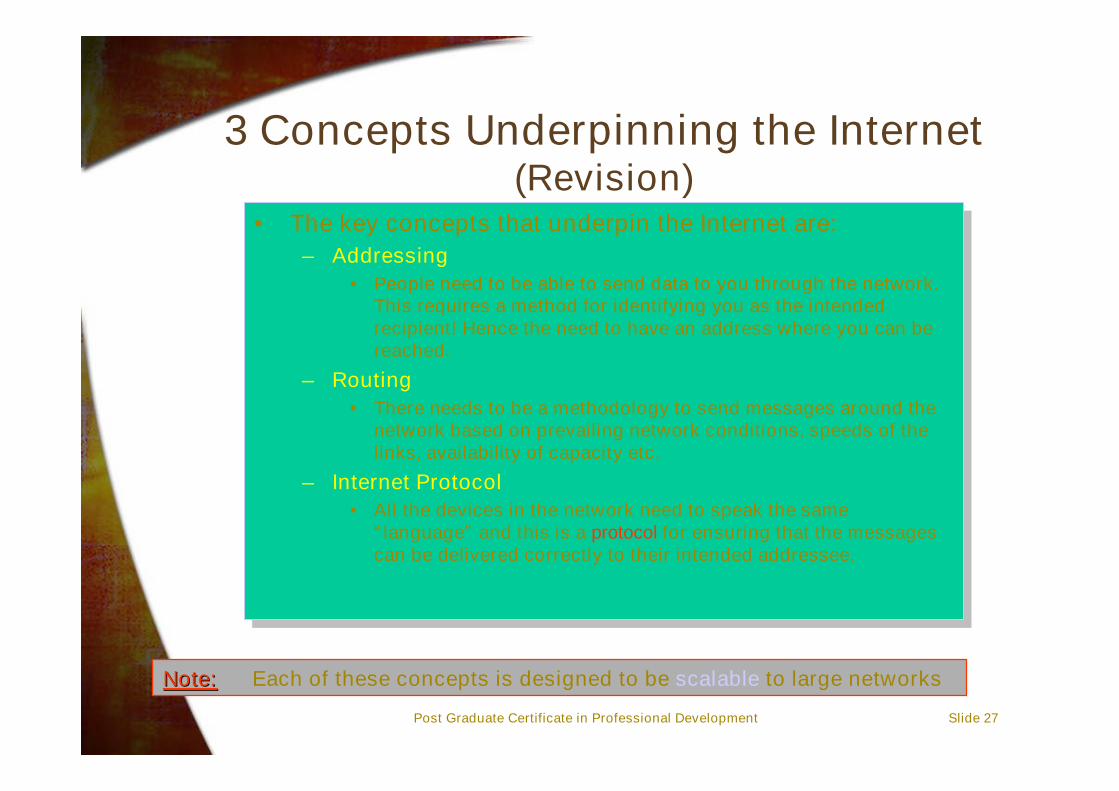
3 Concepts Underpinning the Internet(Revision)
• The key concepts that underpin the Internet are:– Addressing
• People need to be able to send data to you through the network.This requires a method for identifying you as the intendedrecipient! Hence the need to have an address where you can bereached.
– Routing• There needs to be a methodology to send messages around the
network based on prevailing network conditions, speeds of thelinks, availability of capacity etc.
– Internet Protocol• All the devices in the network need to speak the same
“language” and this is a protocol for ensuring that the messagescan be delivered correctly to their intended addressee.
Note:Note: Each of these concepts is designed to be scalable to large networks

Post Graduate Certificate in Professional Development Slide 28
Addressing - 1
• An Internet Protocol address (“IP address”) corresponds to a host-interface card - ie a device that connects a computer to a network.
• If a computer has more than one interface card it will require more thanone IP address.
• IP addresses are set up in a two-part hierarchy:– Network number– Interface number (also called a host number)
• Both the network and interface numbers are unique so that we canuniquely identify the device/card that is connected to the network.
Post Graduate Certificate in Professional Development Slide 29
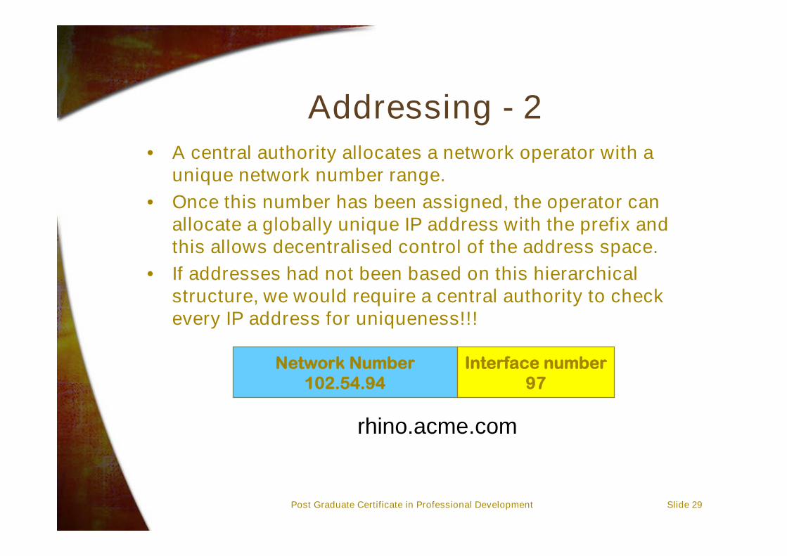
Addressing - 2• A central authority allocates a network operator with a
unique network number range.• Once this number has been assigned, the operator can
allocate a globally unique IP address with the prefix andthis allows decentralised control of the address space.
• If addresses had not been based on this hierarchicalstructure, we would require a central authority to checkevery IP address for uniqueness!!!
Network Number102.54.94
Interface number97
rhino.acme.com
Post Graduate Certificate in Professional Development Slide 30
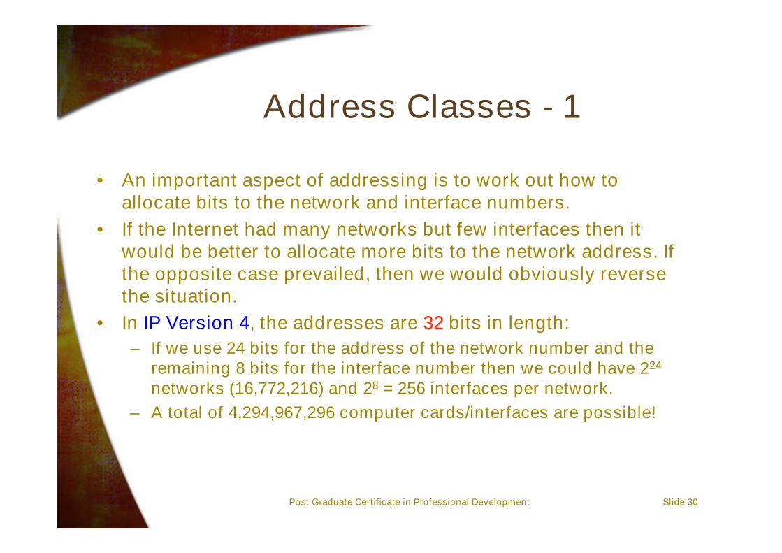
Address Classes - 1
• An important aspect of addressing is to work out how toallocate bits to the network and interface numbers.
• If the Internet had many networks but few interfaces then itwould be better to allocate more bits to the network address. Ifthe opposite case prevailed, then we would obviously reversethe situation.
• In IP Version 4, the addresses are 3232 bits in length:– If we use 24 bits for the address of the network number and the
remaining 8 bits for the interface number then we could have 224
networks (16,772,216) and 28 = 256 interfaces per network.– A total of 4,294,967,296 computer cards/interfaces are possible!

Post Graduate Certificate in Professional Development Slide 31
Address Classes - 2
• Internet designers initially thought there would only be 256networks so the situation described would have beenreversed!
• In fact, a rather more flexible scheme was adopted, viz:– Partition the address space into Class A, Class B, Class C and
Class D addresses with different numbers of bits assigned tothe network and interface numbers in each class.
– A Class A address has 8 bits for the network number and 24bits for the interface number.
– A single large part of the Internet would use a Class Aaddress.
– But by contrast, a Class C address has 24 bits of networknumber and only 8 bits of interface number. This means thatonly 256 hosts can be accommodated in a Class C network.

Post Graduate Certificate in Professional Development Slide 32
Address Classes - 3
• The network can distinguishbetween the 4 classes of addressby the first few bits of the networknumber:
– Class A - first bit is ‘0’– Class B - first two bits are ‘10’– Class C - first three bits are ‘110’– Class D - first four bits are ‘1110’– Class E - first four bits are ‘1111’
• Used for experimental purposesonly.
• Using these bits from the network number has the effect of reducing the overallnumber of networks in each of the classes.
• Class A networks are only 7 bits long so there can only be 128 large class networks.• Class B networks consists of 14 bits so there can only be 16,384 medium class
networks.
0
0
01
1
Class A
Class B
Class C
Class D
1
0
Class E
1
Post Graduate Certificate in Professional Development Slide 33
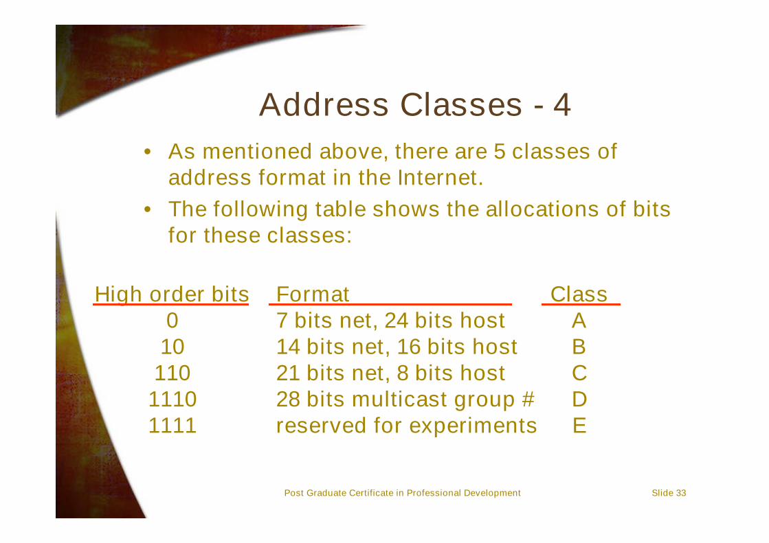
Address Classes - 4• As mentioned above, there are 5 classes of
address format in the Internet.• The following table shows the allocations of bits
for these classes:
High order bits010
11011101111
Format7 bits net, 24 bits host14 bits net, 16 bits host21 bits net, 8 bits host28 bits multicast group #reserved for experiments
ClassABCDE

Post Graduate Certificate in Professional Development Slide 34
Exercise
• Compute the number of Class C networkspossible.
• Hint: A class C address consists of 21 bits for thenetwork number and 8 bits for the interfacenumber. Refer to previous slide…..
•• Your Answer:Your Answer:

Post Graduate Certificate in Professional Development Slide 35
Address Class Problems - 1
• We have stated that IP Version 4 addresses are 32 bits long andcan theoretically address a total of 4,294,967,296 computercards/interfaces.
• In practice, we find that after the central authority hands out theaddress space allocations, there is little control that can beexercised over how much of that space is used. In earlier times,Class A and B spaces were rather freely allocated and rathersparsely used and cannot be reclaimed.
• To solve this problem, IP Version 6 - or IPng has been proposed- this will be discussed at another time.

Post Graduate Certificate in Professional Development Slide 36
Address Class Problems - 2
• If a campus network had more than 256 nodes, it would need aClass B address. This provides 65,536 nodes in the address space,but this is a very large number and typically the campus networkwould not have this many hosts.– Thus, there is considerable wastage if we adopt this approach.
• A solution is to use Classless Inter Domain Routing addresses(CIDR).– In this form of addressing, the network number can be an arbitrary
number of bits long so that the size of the network can be bounded bysome power of 2.

Post Graduate Certificate in Professional Development Slide 37
Internet Addresses - 2• Addresses are usually represented as four
decimal numbers separated using dots.• Each number represents an octet of the address.
– For example, consider 10.0.0.1– The binary representations are
• 00001010 00000000 00000000 00000001
High order bits0
10110
11101111
Format7 bits net, 24 bits host14 bits net, 16 bits host21 bits net, 8 bits host28 bits multicast group #reserved for experiments
ClassABCDE

Post Graduate Certificate in Professional Development Slide 38
Internet Addresses - 3• The two level hierarchy (network and host
numbers) were initially thought to be sufficient,but by 1984, it became clear that a thirdhierarchical level was needed and so the“subnet” was added to the hierarchy at that time.
• This leads to the following format:
Network number Subnet Host
Post Graduate Certificate in Professional Development Slide 39
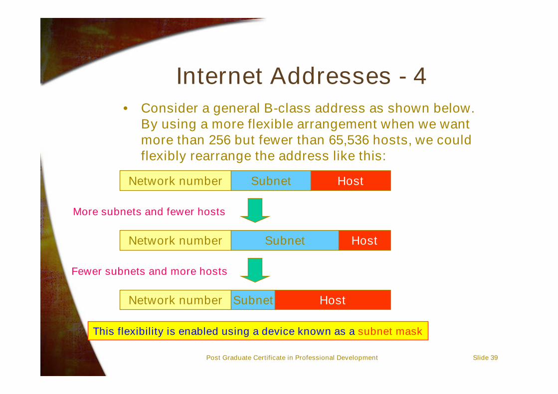
Internet Addresses - 4• Consider a general B-class address as shown below.
By using a more flexible arrangement when we wantmore than 256 but fewer than 65,536 hosts, we couldflexibly rearrange the address like this:
Network number Subnet Host
Network number Subnet Host
Network number Subnet Host
More subnets and fewer hosts
Fewer subnets and more hosts
This flexibility is enabled using a device known as a subnet mask
Post Graduate Certificate in Professional Development Slide 40
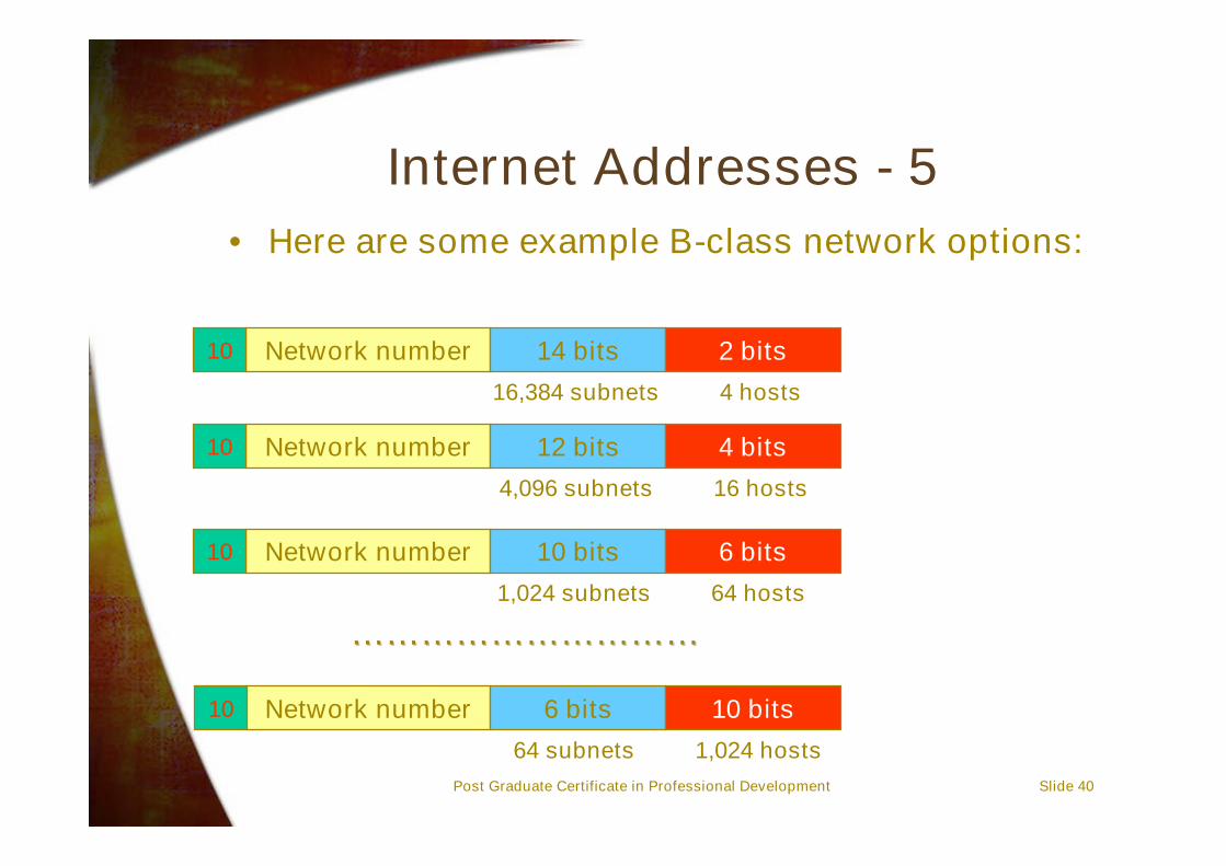
Internet Addresses - 5• Here are some example B-class network options:
Network number 14 bits 2 bits
Network number 12 bits 4 bits
Network number 10 bits 6 bits
16,384 subnets 4 hosts
4,096 subnets 16 hosts
1,024 subnets 64 hosts
Network number 6 bits 10 bits
64 subnets 1,024 hosts
10
10
10
10
……………………………………………………

Post Graduate Certificate in Professional Development Slide 41
Internet Addresses - 6
• The subnet field can have any length - it isspecified by a 32-bit “mask”.
• You find an address belongs to a subnet bycomparison using a mask operation:– This means that all bits of the address for which
the corresponding mask bit is null are zeroedand the result compared to the subnet identifier.
Mask Address Net Subnet Host
0xFFFF00000xFFFFFE00
0xFFFFFFC0
10.27.32.100136.27.33.100136.27.34.141193.27.32.197
A: 10 27 32.100B: 136.27 16 (32) 1.100
136.27 17 (34) 0.141C: 193.27.32 3 (192) 5

Post Graduate Certificate in Professional Development Slide 42
Internet Addresses - 7• Here are three examples of the masks given on the
previous slide in their Hex, Binary and “Dot” formats:
FFFF0000
1111 1111 1111 1111 0000 0000 0000 0000
255 . 255 . 0 . 0
Hex Format
Binary Format
Dot Format
FFFFFE00
255 . 255 . 254 . 0
1111 1111 1111 1111 1111 1110 0000 0000
Hex Format
Binary Format
Dot Format
FFFFFFC0
255 . 255 . 255 . 192
1111 1111 1111 1111 1111 1111 1100 0000
Hex Format
Binary Format
Dot Format

Post Graduate Certificate in Professional Development Slide 43
Exercise• Use the masks shown on the previous slide to
show the Net/Subnet/Host results on the righthand side of the table are correct.
•• Answer:Answer:

Post Graduate Certificate in Professional Development Slide 44
Answers - 1• First we convert the address into binary form:
10.27.32.100
0000 1010 0001 1001 0010 0000 0110 0100 Then we add the mask in binary form:
1111 1111 1111 1111 0000 0000 0000 0000 (Mask)
0000 1010 0001 1001 0000 0000 0000 0000 Then we perform the masking:
A-class address!
Result:
Net: 10 Subnet: 27 Comparison
Host: 32.100
We note that the length of the subnet mask here was the samelength as the length of a normal A-class address in this case.
We note that the length of the subnet mask here was the samelength as the length of a normal A-class address in this case.
Post Graduate Certificate in Professional Development Slide 45
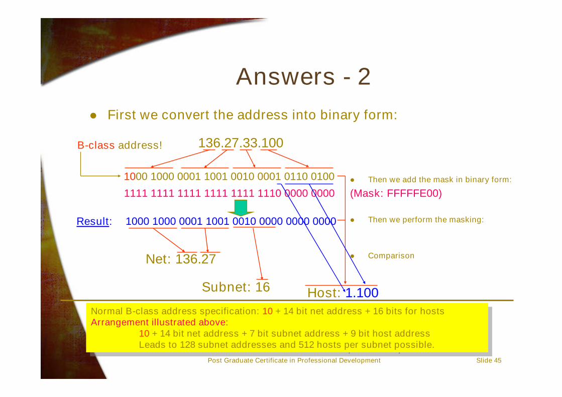
Answers - 2 First we convert the address into binary form:
136.27.33.100
1000 1000 0001 1001 0010 0001 0110 0100 Then we add the mask in binary form:
1111 1111 1111 1111 1111 1110 0000 0000 (Mask: FFFFFE00)
1000 1000 0001 1001 0010 0000 0000 0000 Then we perform the masking:
B-class address!
Result:
Net: 136.27 Comparison
Host: 1.100Subnet: 16
Normal B-class address specification: 10 + 14 bit net address + 16 bits for hostsArrangement illustrated above:
10 + 14 bit net address + 7 bit subnet address + 9 bit host addressLeads to 128 subnet addresses and 512 hosts per subnet possible.
Normal B-class address specification: 10 + 14 bit net address + 16 bits for hostsArrangement illustrated above:
10 + 14 bit net address + 7 bit subnet address + 9 bit host addressLeads to 128 subnet addresses and 512 hosts per subnet possible.

Post Graduate Certificate in Professional Development Slide 46
Answers - 3 First we convert the address into binary form:
136.27.34.141
1000 1000 0001 1001 0010 0010 1000 1101 Then we add the mask in binary form:
1111 1111 1111 1111 1111 1110 0000 0000 (Mask: FFFFFE00)
1000 1000 0001 1001 0010 0010 0000 0000 Then we perform the masking:
B-class address!
Result:
Net: 136.27 Comparison
Host: 0.141Subnet: 17
Normal B-class address specification: 10 + 14 bit net address + 16 bits for hostsArrangement illustrated above:
10 + 14 bit net address + 7 bit subnet address + 9 bit host addressLeads to 128 subnet addresses and 512 hosts per subnet possible.
Normal B-class address specification: 10 + 14 bit net address + 16 bits for hostsArrangement illustrated above:
10 + 14 bit net address + 7 bit subnet address + 9 bit host addressLeads to 128 subnet addresses and 512 hosts per subnet possible.

Post Graduate Certificate in Professional Development Slide 47
Answers - 4 First we convert the address into binary form:
193.27.32.197
1100 0001 0001 1011 0010 0000 1100 0101 Then we add the mask in binary form:
1111 1111 1111 1111 1111 1111 1100 0000 (Mask: FFFFFFC0)
1100 0001 0001 1011 0010 0000 1100 0000 Then we perform the masking:
C-class address!
Result:
Net: 193.27.32 Comparison
Host: 5Subnet: 3
Normal C-class address specification: 110 + 21 bit net address + 8 bits for hostsArrangement illustrated above:
110 + 21 bit net address + 2 bit subnet address + 6 bit host addressLeads to 4 subnet addresses and 64 hosts per subnet possible.
Normal C-class address specification: 110 + 21 bit net address + 8 bits for hostsArrangement illustrated above:
110 + 21 bit net address + 2 bit subnet address + 6 bit host addressLeads to 4 subnet addresses and 64 hosts per subnet possible.

Post Graduate Certificate in Professional Development Slide 48
One more for you to try!
130.50.15.6
1000 0010 0011 0010 0000 1111 0000 0110
1111 1111 1111 1111 1111 1100 0000 0000 (Mask: FFFFFC00)
?-class address?
You do the rest!You do the rest!
Post Graduate Certificate in Professional Development Slide 49
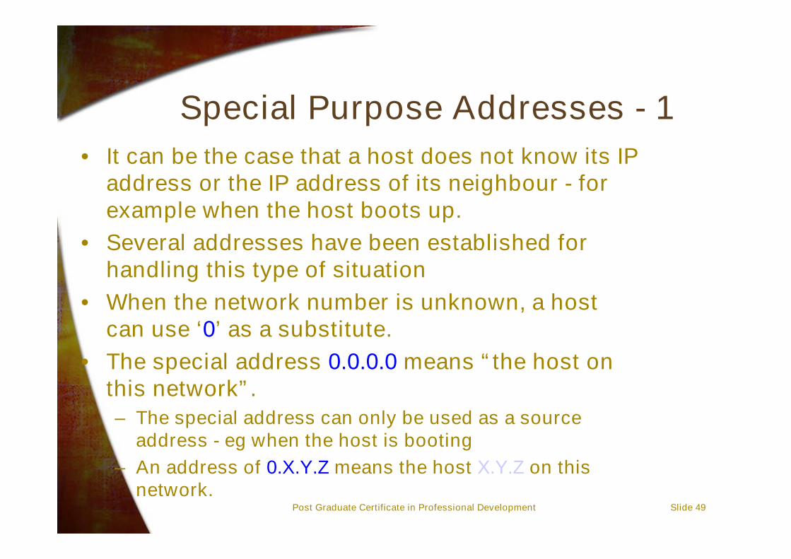
Special Purpose Addresses - 1• It can be the case that a host does not know its IP
address or the IP address of its neighbour - forexample when the host boots up.
• Several addresses have been established forhandling this type of situation
• When the network number is unknown, a hostcan use ‘0’ as a substitute.
• The special address 0.0.0.0 means “the host onthis network”.– The special address can only be used as a source
address - eg when the host is booting– An address of 0.X.Y.Z means the host X.Y.Z on this
network.

Post Graduate Certificate in Professional Development Slide 50
Special Purpose Addresses - 2
• The special address 255.255.255.255 isknown as the limited broadcast address– This address can only be used as a destination
address• Send a packet to all the hosts on the local subnet.• Packets cannot be relayed to any other network
outside of the local one.
• The special addresses A.255.255.255 orB.B.255.255 or C.C.C.255 are referred to asdirected broadcast message addresses.– Packets sent to these addresses are intended to
reach all hosts within the Class A, B or Cnetworks respectively.

Post Graduate Certificate in Professional Development Slide 51
Special Purpose Addresses - 3
• A consequence of this special purpose addressing is thatno subnet is allowed to have a null number, or a numberthat is expressed entirely in binary ones.– If we use 3 bits for the subnet number, for example, then we
can use only the values from 1 - 6.– In addition, we cannot have a subnet with a number that is
only one bit long!!!
• In addition to the above special addresses, Internetnumbering authorities have reserved other special“multicast” addresses as well.
Post Graduate Certificate in Professional Development Slide 52
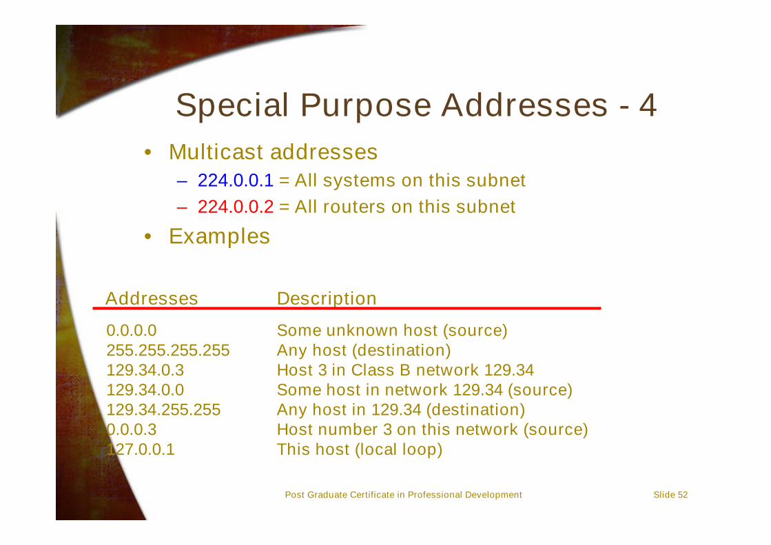
Special Purpose Addresses - 4• Multicast addresses
– 224.0.0.1 = All systems on this subnet– 224.0.0.2 = All routers on this subnet
• Examples
Some unknown host (source)Any host (destination)Host 3 in Class B network 129.34Some host in network 129.34 (source)Any host in 129.34 (destination)Host number 3 on this network (source)This host (local loop)
Addresses Description
0.0.0.0255.255.255.255129.34.0.3129.34.0.0129.34.255.2550.0.0.3127.0.0.1

Post Graduate Certificate in Professional Development Slide 53
Internet Protocol - Introduction• The Internet Protocol will now be presented in
more detail.• The components of interest are:
– Formats– Procedures
• Service types• Fragmentation• Reassembly• Options

Post Graduate Certificate in Professional Development Slide 54
Internet Header - 1
012345678901234567890123456789011 2 3
Version IHL Type of service Total Length
Identification
Protocol
Flags
Header Checksum
Source Address
Destination Address
PaddingOptions
Fragment Offset
Time to live
• The following diagram shows the Internet Headerdetails:
Post Graduate Certificate in Professional Development Slide 55
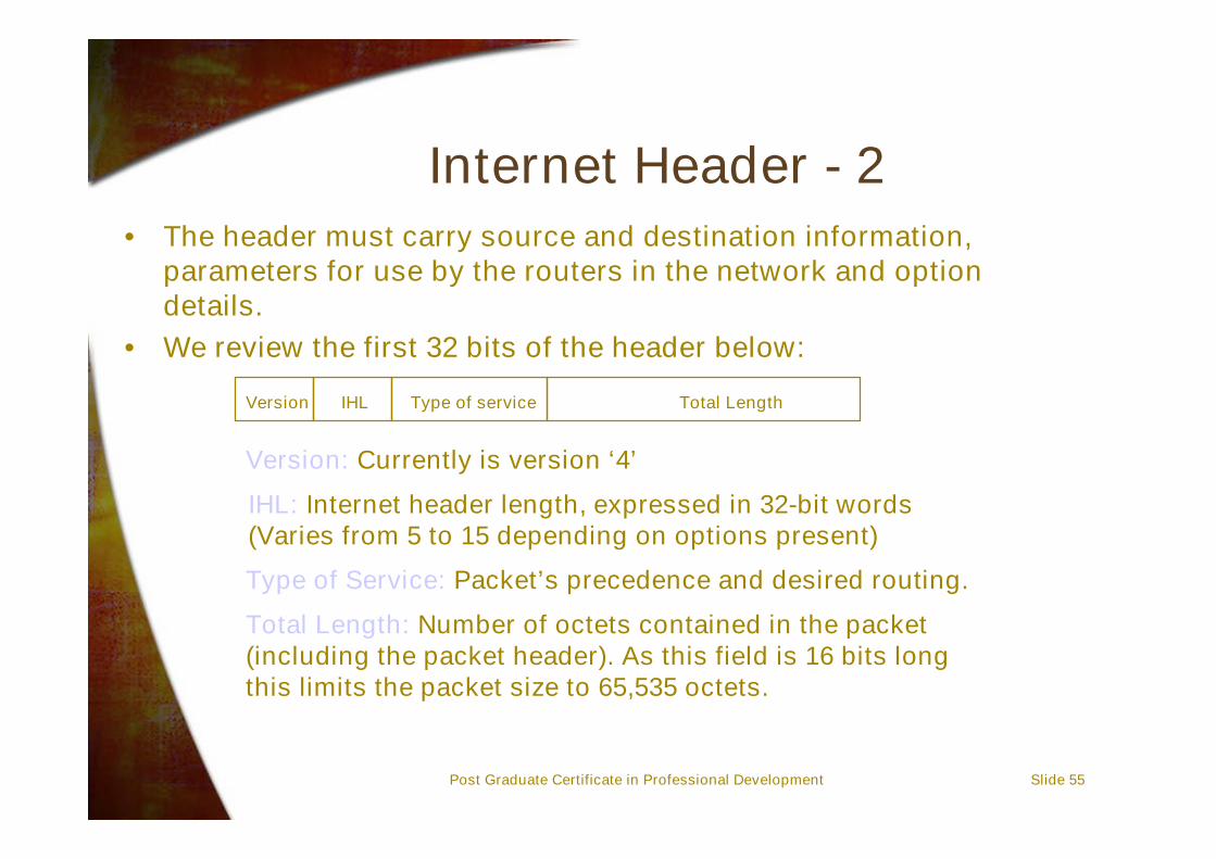
Internet Header - 2• The header must carry source and destination information,
parameters for use by the routers in the network and optiondetails.
• We review the first 32 bits of the header below:
IHL Type of service Total LengthVersion
Version: Currently is version ‘4’
IHL: Internet header length, expressed in 32-bit words(Varies from 5 to 15 depending on options present)
Type of Service: Packet’s precedence and desired routing.
Total Length: Number of octets contained in the packet(including the packet header). As this field is 16 bits longthis limits the packet size to 65,535 octets.

Post Graduate Certificate in Professional Development Slide 56
Internet Header - 3• The identification, flags and fragment offset will
be considered in more detail a little later.• The second 32 bit section is presented below:
Identification Flags Fragment Offset
Post Graduate Certificate in Professional Development Slide 57
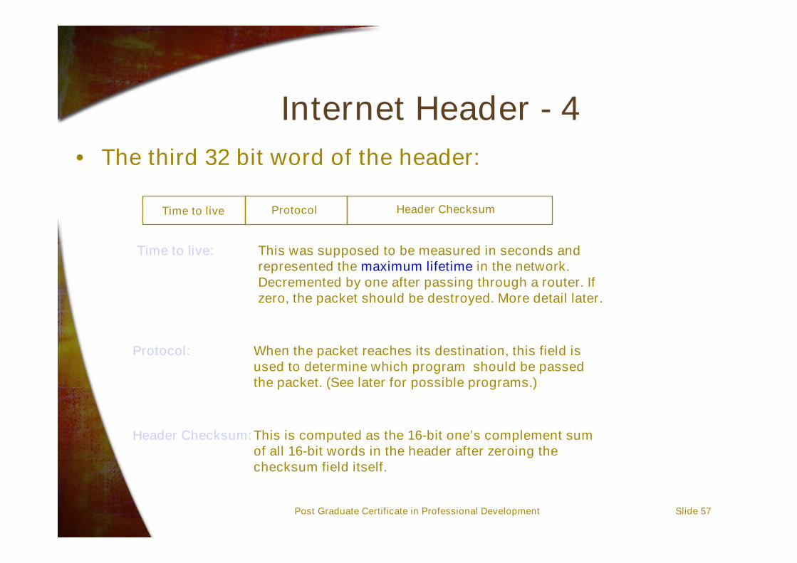
Internet Header - 4• The third 32 bit word of the header:
Time to live Protocol Header Checksum
Time to live: This was supposed to be measured in seconds andrepresented the maximum lifetime in the network.Decremented by one after passing through a router. Ifzero, the packet should be destroyed. More detail later.
Protocol: When the packet reaches its destination, this field isused to determine which program should be passedthe packet. (See later for possible programs.)
Header Checksum:This is computed as the 16-bit one’s complement sumof all 16-bit words in the header after zeroing thechecksum field itself.

Post Graduate Certificate in Professional Development Slide 58
Internet Header - 5• The fourth and fifth 32 bit words from the header
are the source and destination addresses
Source Address
Destination Address
Post Graduate Certificate in Professional Development Slide 59
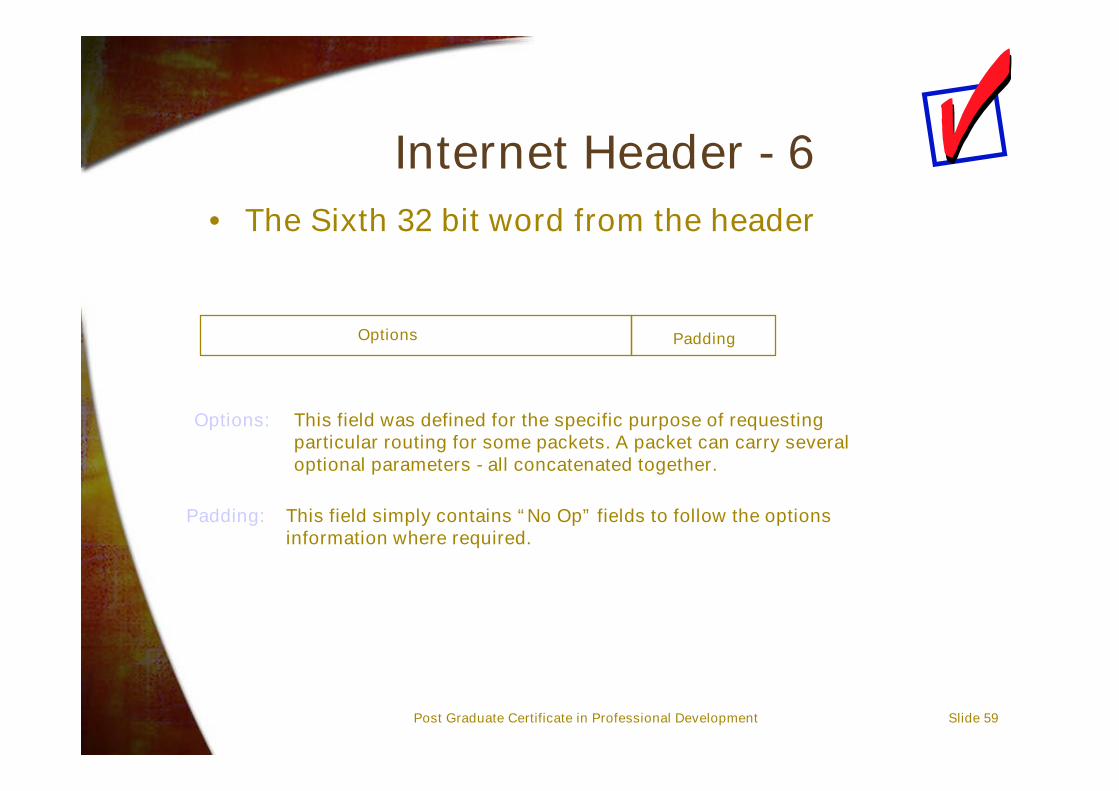
Internet Header - 6• The Sixth 32 bit word from the header
Options Padding
Options: This field was defined for the specific purpose of requestingparticular routing for some packets. A packet can carry severaloptional parameters - all concatenated together.
Padding: This field simply contains “No Op” fields to follow the optionsinformation where required.
Post Graduate Certificate in Professional Development Slide 60
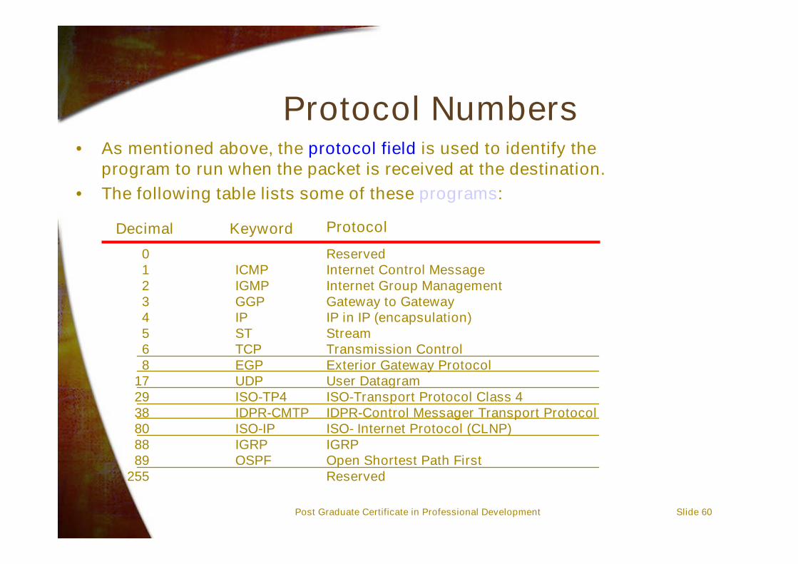
Protocol Numbers• As mentioned above, the protocol field is used to identify the
program to run when the packet is received at the destination.• The following table lists some of these programs:
01234568
172938808889
255
ProtocolKeywordDecimal
ICMPIGMPGGPIPSTTCPEGPUDPISO-TP4IDPR-CMTPISO-IPIGRPOSPF
ReservedInternet Control MessageInternet Group ManagementGateway to GatewayIP in IP (encapsulation)StreamTransmission ControlExterior Gateway ProtocolUser DatagramISO-Transport Protocol Class 4IDPR-Control Messager Transport ProtocolISO- Internet Protocol (CLNP)IGRPOpen Shortest Path FirstReserved

Post Graduate Certificate in Professional Development Slide 61
Precedence and Type of ServiceField
• The type of service field actually carries two sub-fields– Precedence
• An indication of priority
– Type of service• An indication for routing
Precedence Type of service
D T R C
0 1 2 3 4 5 6 7
D - Delay; T - Throughput; R - Reliability; C - Cost
Post Graduate Certificate in Professional Development Slide 62
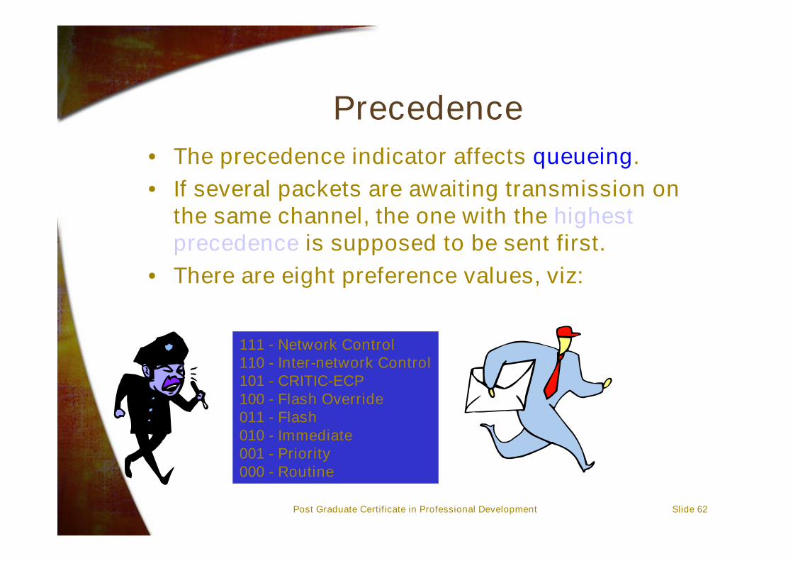
Precedence• The precedence indicator affects queueing.• If several packets are awaiting transmission on
the same channel, the one with the highestprecedence is supposed to be sent first.
• There are eight preference values, viz:
111 - Network Control110 - Inter-network Control101 - CRITIC-ECP100 - Flash Override011 - Flash010 - Immediate001 - Priority000 - Routine
Post Graduate Certificate in Professional Development Slide 63
Type of Service• Often there is more than one route to a
destination. These routes may have quitedifferent characteristics. Eg telephone circuits,satellite links, radio channels,…
• We want to indicate to the routing protocols howwe would like the packet to be routed.
• As indicated above, the four types of service areD, T, R and C:
– D - Delay: This is a mechanism for requesting low delays (avoidsatellite links)
– T - Throughput: Select path with highest throughput (avoid telephonelinks)
– R - Reliability: Highest reliability (avoid radio channels)– C - Cost: Cheapest route
Post Graduate Certificate in Professional Development Slide 64
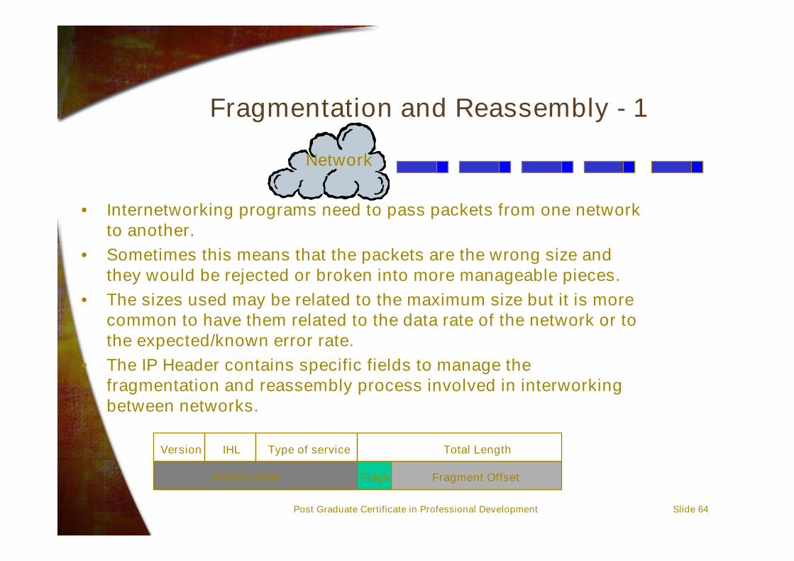
Fragmentation and Reassembly - 1
• Internetworking programs need to pass packets from one networkto another.
• Sometimes this means that the packets are the wrong size andthey would be rejected or broken into more manageable pieces.
• The sizes used may be related to the maximum size but it is morecommon to have them related to the data rate of the network or tothe expected/known error rate.
• The IP Header contains specific fields to manage thefragmentation and reassembly process involved in interworkingbetween networks.
Version IHL Type of service Total Length
Identification Flags Fragment Offset
Network

Post Graduate Certificate in Professional Development Slide 65
Fragmentation and Reassembly - 2
• The flags field has three bits.• The first bit is reserved for future use and must
be set to zero.• The DF bit means don’t fragment. If this bit is set,
then the router should discard the packet if it istoo large. (An ICMP error message needs to bereturned to the source address - if possible.)
• The MF bit means more fragments to follow.
Flags0
DF
MF
0 1 2
Post Graduate Certificate in Professional Development Slide 66
Options and Header Processing• Options are not used very often in modern
internets and intranets– There is an overhead penalty in processing these
options in the header.– Alternative approaches have been found - particularly
for high speed networks.
Where to now?IP Version 6/IPng
The future of the Internet Protocol
Professor Richard Harris

Slide 68
Presentation Outline• IP Version 6 Background/History• IPv6 Overview• New Header format• Extension Headers and Options• Quality of Service• Security• ICMP Version 6• Migration Issues

Post Graduate Certificate in Professional Development Slide 69
Objectives• You will be able to discuss the reasons for the
new generation Internet Protocol• You will be able to describe the new header
format and the extended capabilities of theprotocol that result from these changes.
• You will understand the need for QoS and QoSparameters
• You will have an appreciation of the issuesinvolved in migrating from the current version ofIP (v4) to the new version IPng.

Post Graduate Certificate in Professional Development Slide 70
History - 1• The Internet Protocol was introduced in the ARPANET in the mid-
1970s.• The version of IP in common use today is IP version 4 (IPv4),
described in Request for Comments (RFC) 791 (September 1981).• IPv4 was never intended for the Internet that we have today, either
in terms of the number of hosts, types of applications, or securityconcerns.
• In the early 1990s, the Internet Engineering Task Force (IETF)recognised that the only way to cope with these changes was todesign a new version of IP to become the successor to IPv4.
• The IETF formed the IP next generation (IPng) Working Group todefine this transitional protocol to ensure long-term compatibilitybetween the current and new IP versions, and support for currentand emerging IP-based applications.
• Work started on IPng in 1991 and several IPng proposals weresubsequently drafted.
Post Graduate Certificate in Professional Development Slide 71
History - 2• The result of this effort was IP version 6 (IPv6),
described in RFCs 1883-1886.• These four RFCs were officially listed in
December 1995.• IPv6 is designed as an evolution from IPv4 rather
than as a radical change.• Useful features of IPv4 were carried over in IPv6
and less useful features were dropped.

Post Graduate Certificate in Professional Development Slide 72
IP Version 6 Overview• The key changes from IPv4 to IPv6 can be
summarised as:– Expanded addressing range– Simplified header format– More support for extensions and options– Quality of service capabilities using “flow labelling”.– Extensions to support authentication and privacy issues

Post Graduate Certificate in Professional Development Slide 73
‘New’ Terminology in IPv6• There have been improvements made to terminology to
make things clearer! Here are some examples:• Packet: An IPv6 protocol data unit (PDU), comprising a header
and the associated payload. In IPv4, this would have beentermed packet or datagram.
• Node: A device that implements IPv6.• Router: An IPv6 node that forwards packets, based on the IP
address, not explicitly addressed to itself. In former TCP/IPterminology, this device was often referred to as a gateway.
• Host: Any node that is not a router; these are typically end-usersystems.
• Link: A medium over which nodes communicate with each otherat the Data Link Layer (such as an ATM, frame relay, SMDS widearea network, an Ethernet or token ring LAN).
• Neighbours: Nodes attached to the same link.
Post Graduate Certificate in Professional Development Slide 74
Addressing• Expanded Addressing Capabilities:
– The IP address size is increased from 32 bits to 128 bitsin IPv6, supporting a much greater number ofaddressable nodes, more levels of addressinghierarchy, and simpler auto configuration of addressesfor remote users.
– The scalability of multicast routing is improved byadding a Scope field to multicast addresses.
– A new type of address, called anycast, is also defined.
• According to some sources, 2128 is greater thanthe number of molecules that are present in theuniverse!

Post Graduate Certificate in Professional Development Slide 75
New IPng Header Format• Header Format Simplification: Some IPv4 header fields
have been dropped or made optional to reduce packetprocessing and to limit the bandwidth cost of the IPv6header.
• Note that although IPv6 addresses are four times the size ofIPv4 addresses, the basic IPv6 header is only twice the sizeof an IPv4 header, thus decreasing the impact of the largeraddress fields.
• The old and new header formats are shown in the next fewslides.

Post Graduate Certificate in Professional Development Slide 76
Old IP Version 4 Header
012345678901234567890123456789011 2 3
Version IHL Type of service Total Length
Identification
Protocol
Flags
Header Checksum
Source Address
Destination Address
PaddingOptions
Fragment Offset
Time to live
This is the old header format used in Version 4.
Post Graduate Certificate in Professional Development Slide 77
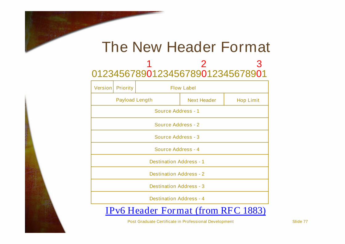
The New Header Format
012345678901234567890123456789011 2 3
Version Priority Flow Label
Payload Length Next Header
Source Address - 1
Destination Address - 4
Hop Limit
Source Address - 2
Source Address - 3
Source Address - 4
Destination Address - 3
Destination Address - 2
Destination Address - 1
IPv6 Header Format (from RFC 1883)
Post Graduate Certificate in Professional Development Slide 78
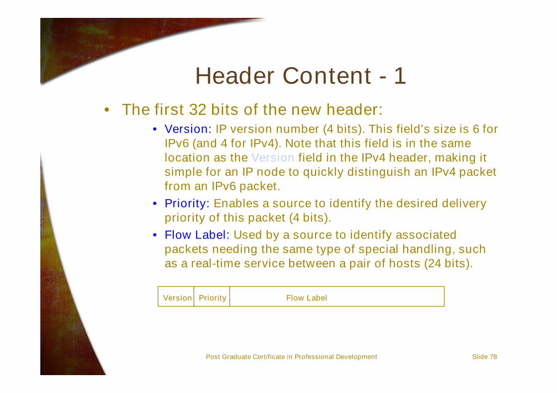
Flow Label
Header Content - 1• The first 32 bits of the new header:
• Version: IP version number (4 bits). This field's size is 6 forIPv6 (and 4 for IPv4). Note that this field is in the samelocation as the Version field in the IPv4 header, making itsimple for an IP node to quickly distinguish an IPv4 packetfrom an IPv6 packet.
• Priority: Enables a source to identify the desired deliverypriority of this packet (4 bits).
• Flow Label: Used by a source to identify associatedpackets needing the same type of special handling, suchas a real-time service between a pair of hosts (24 bits).
Version Priority
Post Graduate Certificate in Professional Development Slide 79
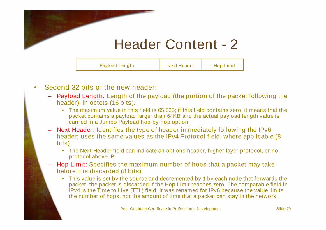
Header Content - 2
• Second 32 bits of the new header:– Payload Length: Length of the payload (the portion of the packet following the
header), in octets (16 bits).• The maximum value in this field is 65,535; if this field contains zero, it means that the
packet contains a payload larger than 64KB and the actual payload length value iscarried in a Jumbo Payload hop-by-hop option.
– Next Header: Identifies the type of header immediately following the IPv6header; uses the same values as the IPv4 Protocol field, where applicable (8bits).
• The Next Header field can indicate an options header, higher layer protocol, or noprotocol above IP.
– Hop Limit: Specifies the maximum number of hops that a packet may takebefore it is discarded (8 bits).
• This value is set by the source and decremented by 1 by each node that forwards thepacket; the packet is discarded if the Hop Limit reaches zero. The comparable field inIPv4 is the Time to Live (TTL) field; it was renamed for IPv6 because the value limitsthe number of hops, not the amount of time that a packet can stay in the network.
Payload Length Next Header Hop Limit
Post Graduate Certificate in Professional Development Slide 80
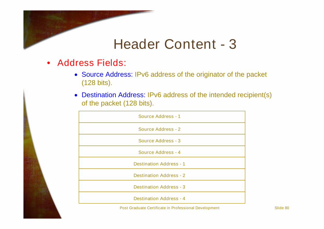
Header Content - 3• Address Fields:
Source Address: IPv6 address of the originator of the packet(128 bits).
Destination Address: IPv6 address of the intended recipient(s)of the packet (128 bits).
Source Address - 1
Destination Address - 4
Source Address - 2
Source Address - 3
Source Address - 4
Destination Address - 3
Destination Address - 2
Destination Address - 1

Post Graduate Certificate in Professional Development Slide 81
Extension Headers and Options• Improved Support for Extensions and Options:
– IPv6 header options are encoded in such a way to allowfor more efficient forwarding, less stringent limits on thelength of options, and greater flexibility for introducingnew options in the future.
– Some fields of an IPv4 header have been made optionalin IPv6.

Post Graduate Certificate in Professional Development Slide 82
Values for the Next Header Field
Value Contents of the next header1 Internet Control Message Protocol (ICMP)6 Transmission Control Protocol (TCP)17 User Datagram Protocol (UDP)43 Routing header44 Fragment header58 Internet Control Message Protocol version 6 (ICMPv6)59 Nothing; this is the final header60 Destination Options header89 Open Shortest Path First (OSPF)
This table gives possible values for the next headerfield:

Post Graduate Certificate in Professional Development Slide 83
Quality of Service - 1
• Flow Labelling Capability:– A new quality-of-service (QOS) capability has been added to enable the labelling
of packets belonging to particular traffic “flows” for which the sender requestsspecial handling, such as a real-time service.
– It should be noted that the concept of a flow in IP is a major departure from IPv4and most other connectionless protocols.
– Special handling for non-default quality-of-service is an important capability inorder to support applications that require guaranteed throughput, end-to-enddelay, and/or jitter, such as multimedia or real-time communication. These QOSparameters are an extension of IPv4's Type of Service (TOS) capability.
– The Priority field allows the source to identify the desired priority of a packet.Values 0–7 are used for congestion-controlled traffic, or traffic that backs off inresponse to network congestion, such as TCP segments.

Post Graduate Certificate in Professional Development Slide 84
Quality of Service - 2
Uncharacterised traffic“Filler” traffic (eg. Netnews)Unattended data transfer (eg. e-mail)(reserved)Attended bulk transfer (eg. FTP, HTTP, NFS)(reserved)Interactive traffic (eg. Telnet, X)Internet control traffic (eg. routing protocols, SNMP)
Priority Description
01234567
The following table lists the priority values thatare recommended for congestion-controlled traffic:
For non-congestion controlled traffic, the values of priority start at ‘8’ for packetsthat could be discarded up to priority ‘15’ that are least willing to be discarded.
For non-congestion controlled traffic, the values of priority start at ‘8’ for packetsthat could be discarded up to priority ‘15’ that are least willing to be discarded.
Post Graduate Certificate in Professional Development Slide 85
Security• Authentication and Privacy Capabilities:
– Extensions to support security options, such asauthentication, data integrity, and data confidentiality,are built-in to IPv6.
• IP Version 4 had very few, if any security featuresand this has become a problem in recent years.
• IP Version 6 has two special security features:(see RFC 1826 and RFC 1827 for details)– The IP Authentication Header– The IP Encapsulating Security Payload (ESP)
• These features should add to the overall securityof the new protocol.

Post Graduate Certificate in Professional Development Slide 86
ICMP Version 6 - 1• As previously discussed, the Internet Control
Message Protocol (ICMP) provides error andinformation messages that are beyond thecapabilities of IP to provide.
• ICMP for IPv6 (ICMPv6) is functionally similar toICMP for IPv4 and uses a similar message format,and forms an important and integral part of IPv6.
• ICMPv6 messages are carried in an IPv6datagram with a Next Header field value of 58.

Post Graduate Certificate in Professional Development Slide 87
ICMP Version 6 - 2• ICMPv6 error messages are:
• Destination Unreachable: Sent when a packet cannot bedelivered to its destination address for reasons other thancongestion
• Packet Too Big: Sent by a router when it has a packet thatit cannot forward because the packet is larger than theMTU of the outgoing link
• Time Exceeded: Sent by a router that when the packet'sHop Limit reaches zero or if all fragments of a datagramare not received within the fragment reassembly time
• Parameter Problem: Sent by a node that finds someproblem in a field in the packet header that results in aninability to process the header).

Post Graduate Certificate in Professional Development Slide 88
Migration Issues
• Before IPv6 can be widely deployed, the networkinfrastructure must be upgraded to employ software thataccommodates the new protocol.
• In addition, the new address format must be accommodatedby every TCP/IP protocol that uses addresses.
– The Domain Name System (DNS), for example, has defined anAAAA resource record for IPv6 128-bit addresses (IPv4's 32-bitaddresses use an A record) and the IP6.INT address domain(IPv4 uses the ARPA address domain).
– Other protocols that must be modified for IPv6 include DHCP,the Address Resolution Protocol (ARP) family, and IP routingprotocols such as the Routing Information Protocol (RIP), OpenShortest Path First (OSPF) protocol, and the Border GatewayProtocol (BGP). Only after the routers and the backbones areupgraded will hosts start to transition to the new protocol andapplications be modified to take advantage of IPv6'scapabilities.

Post Graduate Certificate in Professional Development Slide 89
IPv4 and IPv6 Co-existence
• The above diagram shows a possible scenario forfuture co-existence in the transition period.
IPv4Network
IPv6Network IPv4/IPv6
RouterIPv4/IPv6
Router
IPv6Network