The Influence of Explosion Relief Vent Layouts on ... · International standards for dust explosion...
6
CHEMICAL ENGINEERING TRANSACTIONS VOL. 48, 2016 A publication of The Italian Association of Chemical Engineering Online at www.aidic.it/cet Guest Editors: Eddy de Rademaeker, Peter Schmelzer Copyright © 2016, AIDIC Servizi S.r.l., ISBN 978-88-95608-39-6; ISSN 2283-9216 The Influence of Explosion Relief Vent Layouts on Explosion Overpressures in Large Biomass Storage Vessels Prankul Middha, Rohan Samaraweera*, Chris Coffey, David W. Price Gexcon UK Ltd., Hattersley House, Hattersley Court, Burscough Road, Lancashire, L39 2AY, United Kingdom rohan@gexcon.com International standards for dust explosion relief design (NFPA 68 2013, EN 14491 2012, VDI 3673) have largely been developed for conventional bulk material handling silos with volumes of less than 10,000 m 3 , with empirical calculations being used to determine the total suitable vent areas required to achieve explosion protection in the event of an internal incipient explosion. However, these standards generally do not advise on the effects of the distribution of this total area across the vessel. Some standards state that the distribution of the relief vent area is unimportant as long as the total required vent area is achieved. For larger vessels, such as large biomass storage silos with volumes up to 100,000 m 3 , Computational Fluid Dynamics (CFD) codes are often used to undertake explosion simulations in order to determine the effects of likely worst-case explosions and subsequently determine a suitable area of explosion relief venting. The effects of the distribution of these vent areas is again not often considered in the design of such vessels. This paper presents the results of research undertaken by Gexcon using the FLACS-DustEx CFD code, showing the effects of various relief vent arrangements for a given vessel and given total relief vent area. The initial results suggest that flames emitted through relief vents during an explosion can interact with one another outside of the vessel, increasing turbulence and reducing the efficiency of the venting process. This subsequently results in an increase in the reduced explosion pressure (P red ) within the vessel during an explosion. The level of interaction, and hence the magnitude of the change in the reduced overpressure, has been found to vary with the manner in which the total vent area is distributed across the vessel. The results of this initial research are discussed, along with preliminary conclusions and recommendations. Other aspects are also discussed, such as statements in the standards that may be misleading and the effects of structures located in-between large areas of relief vents on a vessel. 1. Introduction Biomass power plants frequently store biomass material (typically in pellet form) in very large storage silos. This allows a continuous power generation operation as there is always a large store of material available. These silos can be built so large that they have volumes up to 100,000 m 3 . Biomass material is usually transported into the storage silos via conveyors, which drop the material in from the top of the silo roof. During filling or emptying operations, large dust clouds can potentially be created as a result of dust brought in with the pellets and even with clean pellets from attrition due to the pellets striking one another during free fall and on impact with the pile. Clouds of fine, dry biomass dust are highly explosive due to their large surface area for a given mass. The presence of these clouds poses a significant safety risk should an effective ignition source be present inside the silo at the same time as a dust cloud having its concentration within explosive limits. Explosion relief venting is a common concept used to reduce the potential consequences of dust cloud explosions in silos and other vessels. Several venting panels are located on a silo, which yield at a predetermined low pressure. This allows relief of the pressure building up inside the silo during an explosion event and therefore reduces the maximum pressure realised within the silo. International standards for the design of explosion relief venting (NFPA 68 2013, EN 14491 2012, VDI 3673) were developed for smaller vessels with volumes less than 10,000 m 3 , with empirical calculations to determine the total vent area required to achieve explosion protection in the event of an internal explosion. However, these standards generally do not advise on the effects of the distribution of this total area across the vessel. Some standards state that the DOI: 10.3303/CET1648035 Please cite this article as: Middha P., Samaraweera R., Coffey C., Price D., 2016, The influence of explosion relief vent layouts on explosion overpressures in large biomass storage vessels, Chemical Engineering Transactions, 48, 205-210 DOI:10.3303/CET1648035 205
Transcript of The Influence of Explosion Relief Vent Layouts on ... · International standards for dust explosion...

CHEMICAL ENGINEERING TRANSACTIONS
VOL. 48, 2016
A publication of
The Italian Association of Chemical Engineering Online at www.aidic.it/cet
Guest Editors: Eddy de Rademaeker, Peter SchmelzerCopyright © 2016, AIDIC Servizi S.r.l., ISBN 978-88-95608-39-6; ISSN 2283-9216
The Influence of Explosion Relief Vent Layouts on Explosion Overpressures in Large Biomass Storage Vessels
Prankul Middha, Rohan Samaraweera*, Chris Coffey, David W. Price Gexcon UK Ltd., Hattersley House, Hattersley Court, Burscough Road, Lancashire, L39 2AY, United Kingdom [email protected]
International standards for dust explosion relief design (NFPA 68 2013, EN 14491 2012, VDI 3673) have largely been developed for conventional bulk material handling silos with volumes of less than 10,000 m3, with empirical calculations being used to determine the total suitable vent areas required to achieve explosion protection in the event of an internal incipient explosion. However, these standards generally do not advise on the effects of the distribution of this total area across the vessel. Some standards state that the distribution of the relief vent area is unimportant as long as the total required vent area is achieved. For larger vessels, such as large biomass storage silos with volumes up to 100,000 m3, Computational Fluid Dynamics (CFD) codes are often used to undertake explosion simulations in order to determine the effects of likely worst-case explosions and subsequently determine a suitable area of explosion relief venting. The effects of the distribution of these vent areas is again not often considered in the design of such vessels. This paper presents the results of research undertaken by Gexcon using the FLACS-DustEx CFD code, showing the effects of various relief vent arrangements for a given vessel and given total relief vent area. The initial results suggest that flames emitted through relief vents during an explosion can interact with one another outside of the vessel, increasing turbulence and reducing the efficiency of the venting process. This subsequently results in an increase in the reduced explosion pressure (Pred) within the vessel during an explosion. The level of interaction, and hence the magnitude of the change in the reduced overpressure, has been found to vary with the manner in which the total vent area is distributed across the vessel. The results of this initial research are discussed, along with preliminary conclusions and recommendations. Other aspects are also discussed, such as statements in the standards that may be misleading and the effects of structures located in-between large areas of relief vents on a vessel.
1. Introduction
Biomass power plants frequently store biomass material (typically in pellet form) in very large storage silos. This allows a continuous power generation operation as there is always a large store of material available. These silos can be built so large that they have volumes up to 100,000 m3. Biomass material is usually transported into the storage silos via conveyors, which drop the material in from the top of the silo roof. During filling or emptying operations, large dust clouds can potentially be created as a result of dust brought in with the pellets and even with clean pellets from attrition due to the pellets striking one another during free fall and on impact with the pile. Clouds of fine, dry biomass dust are highly explosive due to their large surface area for a given mass. The presence of these clouds poses a significant safety risk should an effective ignition source be present inside the silo at the same time as a dust cloud having its concentration within explosive limits. Explosion relief venting is a common concept used to reduce the potential consequences of dust cloud explosions in silos and other vessels. Several venting panels are located on a silo, which yield at a predetermined low pressure. This allows relief of the pressure building up inside the silo during an explosion event and therefore reduces the maximum pressure realised within the silo. International standards for the design of explosion relief venting (NFPA 68 2013, EN 14491 2012, VDI 3673) were developed for smaller vessels with volumes less than 10,000 m3, with empirical calculations to determine the total vent area required to achieve explosion protection in the event of an internal explosion. However, these standards generally do not advise on the effects of the distribution of this total area across the vessel. Some standards state that the
DOI: 10.3303/CET1648035
Please cite this article as: Middha P., Samaraweera R., Coffey C., Price D., 2016, The influence of explosion relief vent layouts on explosion overpressures in large biomass storage vessels, Chemical Engineering Transactions, 48, 205-210 DOI:10.3303/CET1648035
205

distribution of the relief vent area is unimportant as long as the total required vent area is achieved. For the much larger silos commonly encountered on modern plants with volumes greater than 10,000 m3, there is no particular guidance or standard to refer to. Therefore, Computational Fluid Dynamics (CFD) codes are often used to undertake explosion simulations for such larger silos in order to determine the likely results of worst-case explosion scenarios. The effects of the layout of relief vents on such silos are also not usually considered during design. This paper presents the results of CFD simulations undertaken by Gexcon, to examine the effects of varying the distribution of relief vents on the maximum reduced pressure realised within a silo. Simulations have been undertaken for a silo of a size and proportions for which the EN 14491 2012 standard is applicable, as well as a larger silo similar to those found in biomass power plants.different from the ones mentioned here.
2. Methodology
2.1 Software The simulations described in this paper were performed with the CFD code FLACS-DustEx formally known as DESC (Dust Explosion Simulation Code). DESC was developed as part of an EU funded project (Skjold, 2007). Large amounts of validation work have been conducted to ensure the accuracy of the code. DustEx can be used to determine the pressures realised for any size and shape of silo containing any size and shape of dust cloud. DustEx has been used extensively in industrial projects addressing, for example, the external effects of vented silos, the typical reduction in vent area for larger silos in comparison with empirical calculations, the potential for secondary explosions and understanding zones requiring restricted access.
2.2 Fuel representation ‘Fuel files’ are used to represent the properties of the dust material being modelled in the simulations. Two of the most important fuel properties that need to be accurately modelled are Pmax (the maximum pressure realised during combustion of the material in an enclosed vessel) and Kst max (the maximum rate of pressure rise realised during combustion of the material in an enclosed vessel). In the cases presented in this paper, the fuel modelled was wood dust with properties of Pmax = 9 bar and Kst max = 210 bar.m/s. This represents fairly typical wood dust properties encountered at biomass power plants. A dust concentration of 450 g/m3 was used for the dust cloud to represent the worst case concentration.
2.3 Geometrical model Two geometrical models were created for use in the simulations. The first was a small silo that consisted of a simple cylindrical silo structure with a flat roof. The silo was 25 m tall with a diameter of 20 m, resulting in a total internal volume of 7,854 m3. Square holes were cut into the roof of the silo to represent the free areas of the explosion relief vents. Initially, one large hole was cut into the silo roof to represent a single zone of vent panels placed next to one another in the centre of the silo roof. This zone was then split into two zones on either side of the silo roof to represent two distinct zones of relief vents. The zone was then split into four and eight separate zones. The discrete venting zones created in the silo roof are shown in Figure 1 below. The EN 14491 2012 standard was used to determine the total required vent area for a silo of this type with a Pred value (the reduced overpressure, i.e. the maximum overpressure realised within the silo after the explosion relief vents have yielded) of 0.3 barg. According to the standard, the total required vent area was 135 m2. Therefore, this area was defined in the explosion simulations as the total available vent area. The second geometrical model was of a larger silo, similar to the types of large biomass storage silos found at modern biomass power plants. This model consisted of a cylindrical silo structure with a flat roof. This silo was 40 m tall, with a diameter of 35 m, resulting in a silo volume of 38,485 m3. As this volume is significantly larger than the 10,000 m3 that the EN 14491 2012 standard applies to, an arbitrary total vent area was defined for this silo. Initially, one large venting zone was created in the centre of the roof of this silo. This zone was then split into two zones, which were subsequently moved further apart from each other. The objective of these simulations was to investigate the effects of the distance between separate venting zones. The reason these simulations were undertaken on a much larger silo model was that on a smaller silo there is insufficient roof space to separate the venting zones by a large enough distance to see the effects of this separation distance. Furthermore, larger silos of this type are frequently used at biomass sites and it was therefore also of interest to determine if the scale of the silo had any significant influence on the vent layout effects.
2.4 Scenarios and simulation setup The EN 14491 2012 standard assumes a homogeneous stoichiometric dust cloud filling 100% of the silo volume when calculating the required total vent area, therefore the initial dust cloud defined inside the silo simulations also occupied 100% of the silo volume, in order for the simulation results to be compared to the EN standard predictions. Ignition was defined at the bottom of the silo to represent a worst-case scenario, as
206
this gives the longest flame path distance to the vent panels, resulting in a longer time for flame acceleration and pressure build-up. Vent panels were defined in the holes cut out of the silo roof geometry to represent the explosion relief vents. These were given a static opening pressure of 0.1 bar, i.e. the pressure at which the vent panels will yield. This is a typical value for vent panels commonly used on large biomass storage silos. A final area porosity of 90% was defined for the vent panels, to represent framing and other structural details that may remain after the vent panels have yielded. The computational grid was refined in the area around the silo and vertically above the silo roof to ensure that the flow and combustion details were captured accurately in the areas of interest. The refined cells in this region were 0.5 m cubes. The grid was stretched in all directions to the domain boundaries, resulting in a total grid size of 3,684,200 cells.
Figure 1. Plan view of the silo roof used in the simulations of the small silo showing the varying vent layouts modelled (left) and perspective view of one of the small silo models (right).
3. Results and Discussion
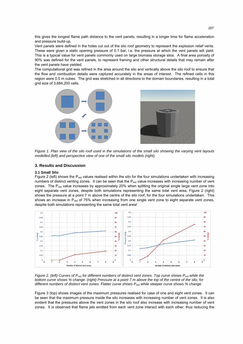
3.1 Small Silo Figure 2 (left) shows the Pred values realised within the silo for the four simulations undertaken with increasing numbers of distinct venting zones. It can be seen that the Pred value increases with increasing number of vent zones. The Pred value increases by approximately 20% when splitting the original single large vent zone into eight separate vent zones, despite both simulations representing the same total vent area. Figure 2 (right) shows the pressure at a point 7 m above the centre of the silo roof, for the four simulations undertaken. This shows an increase in Pred of 75% when increasing from one single vent zone to eight separate vent zones, despite both simulations representing the same total vent area!
Figure 2. (left) Curves of Pred for different numbers of distinct vent zones. Top curve shows Pred while the bottom curve shows % change. (right) Pressure at a point 7 m above the top of the centre of the silo, for different numbers of distinct vent zones. Flatter curve shows Pred while steeper curve shows % change.
Figure 3 (top) shows images of the maximum pressures realised for case of one and eight vent zones. It can be seen that the maximum pressure inside the silo increases with increasing number of vent zones. It is also evident that the pressures above the vent zones in the silo roof also increase with increasing number of vent zones. It is observed that flame jets emitted from each vent zone interact with each other, thus reducing the
207

efficiency of the venting process. The higher the number of separate vent zones, the greater the level of interaction between the jets and therefore the more significant the reduction in the venting process efficiency. Figure 3 (bottom) presents images of approximate flame path for each of the four simulations. The interaction of jets emitted from the vent zones (discussed in the previous paragraph) is observed in these images. It can be seen that with a single large vent zone, a well-defined jet is issued from the zone with significant momentum. With increasing number of vent zones, the jets become less well-defined and the flame path tends to be less directional with a slightly greater lateral spread. It is predicted that if these separate vent zones were moved further apart from one another, such that the jets were not close enough to interact with each other, the effect of increasing the number of vent zones would be reduced. The objective of the simulations undertaken for the larger silo model was to determine if this was the case or not.
Figure 3. (top-right) Contours of maximum pressure from the simulation with one vent zone (top-left) and eight vent zones. For B/W images, darker colours on the outside are the low pressures above 0.1 barg while darker colours on the inside represent high pressures, around 0.4 barg. (bottom-left) Images showing approximate flame path from the simulation with one vent zone and eight vent zones (bottom-right).
3.2 Large Silo The results of the simulations on the large silo showed that the lowest Pred value was achieved with the single vent zone in the centre of the silo roof. As this zone was split into two zones which were moved further apart, it was found that the Pred value started to increase. After a certain separation distance the Pred value began to decrease back towards the original value. Figure 4 illustrates this concept. The individual Pred values for each simulation undertaken have been omitted from this paper for brevity. As was observed in the simulations of the small silo, the interaction of flame jets emitted from the separate vent zones reduces the efficiency of the venting process, thus increasing the Pred value. However, as the vent zones are moved far enough away from each other that the jets do not interact with each other, this effect is reduced, and the Pred value decreases. The issues observed in the simulations undertaken essentially result in a reduction of the total effective vent area, which results in an increased Pred value within the silo. The Pred value is dependent on many different variables, therefore the number or spacing of distinct vent zones may not always have a significant effect, as other factors could become more dominant. This suggests that the effects of the layout of explosion vents will be more significant with smaller total vent areas, where the vent area has a larger effect on the resulting Pred value. A typical graph of total vent area vs. Pred shows a curve that levels off with increasing vent area, whereby further increases in the total available vent area do not result in any further reduction in the Pred value. For a given silo, a smaller vent area will be at a point on this curve where the gradient is steep,
208

therefore small changes in the layout of the vent panels, or the number of individual venting zones, could have a small effect on the effective vent area, resulting in a large change in the Pred value. However, for a larger vent area, the flatter gradient at this part of the curve suggests that changes in the effective total vent area will not have a significant effect on Pred. This concept is illustrated in Figure 5.
Figure 4. Illustration of the effects of vent separation distance on Pred for the large silo simulations
Another issue that has been observed in some industrial projects undertaken by Gexcon is the effect of large structures placed on silo roofs on the venting process. It has been observed that these structures can help separate the flame jets from discrete venting zones, thus reducing the interaction between them and therefore reducing the Pred value. Figure 8 shows the approximate flame paths for two large silos modelled by Gexcon, both of which have tall conveyor and head house structures on the silo roofs. It can be seen that these structures provide a division between the two flame jets issued on either side of them, thus reducing the immediate interaction between the jets. This implies that the siting of structures on silo roofs could be defined so as to aid the venting process during an explosion event, if consideration is given to this during design.
4. Conclusions
It was found that increasing the total number of separate venting zones, for a given total vent area, can result in an increase in the Pred value inside a silo, as well as the pressures in the surrounding area which may have an impact on surrounding buildings or structures. This appears to be a result of the interaction of flame jets between separate vent zones, which causes a reduction in venting efficiency. It was also determined that moving vent zones far enough away from each other such that the jets cannot interact with one another, resulted in this effect being reduced. It has been observed during various industrial projects that structures or objects on the silo roof can also affect the Pred value inside a silo. This can occur as objects (such as large conveyors or head houses) can help to separate the jets from separate venting zones, thus reducing the interaction between them. The EN 14491 2012 standard does not provide any guidance in terms of the layout of explosion vent panels on a vessel. However, the present paper has shown that varying the vent layout could potentially result in significant changes in the anticipated Pred value. The EN 14491 2012 standard states the following: “If the enclosure is small and relatively symmetrical, one large vent can be as effective as several small vents of equal combined area. For large enclosures, the location of multiple vents to achieve uniform coverage of the enclosure surface to the greatest extent practicable is recommended.” “The required vent area can, in practical applications, be divided into several smaller areas as long as the total area equals the required vent area.” In light of the results of the simulations presented in this paper, these statements appear to be misleading and it is hoped that, after further work, the standards can be improved to include guidance on the layout of vent panels. It is also anticipated that the results of the simulations presented in this paper can be applied to silo designs, by considering the layout of explosion vent panels early in the design process. A curve of total vent
209

area vs. Pred can be very useful at initial design stages in order to determine where on the curve the current design sits. This would allow the design team to understand if significant changes in Pred are likely to occur from changes to the vent panel layout.
Figure 5. Typical graph showing total available vent area vs. Pred
Figure 6. The effects of large silo roof structures on flame path for two industrial projects undertaken by Gexcon
Nomenclature
Pmax Maximum pressure realised during combustion of a material in an enclosed vessel Kst max Maximum rate of pressure rise realised during combustion of a material in an enclosed
vessel Pred Reduced overpressure – the maximum overpressure realised within a vessel during an
explosion inside the vessel, after the explosion relief vents have yielded
References
Skjold, T., 2007, Review of the DESC project, J. Loss Prevention in the Process Industries, 20: 291-3028 EN 14491 2012: Dust explosion venting protective systems
210