Incremental shaft encoders Incremental thru-Bore & motor ...

(Part of) Working Paper – Do not distribute or quote without permission. Only for CSCI577use.
The Incremental Commitment Spiral Model (ICSM) Barry Boehm, Jo Ann Lane, Supannika Koolmanojwong, Richard Turner
0.1 Introduction to the ICSM
0.1.1 What Is the ICSM?
Figure 1 and Figure 2 show the differences between the original spiral model and the ICSM. The
original spiral model was meant to say that after a project had identified its objectives,
constraints, and alternative solution approaches (OC&As), it would evaluate the alternatives with
respect to those objectives and constraints, and make a risk-driven determination of what to do
next.
If one alternative was clearly superior and feasible, the project could elaborate its lower-level
OC&As into detailed requirements, designs, and plans, and proceed into a build to requirements
approach. However, if there were uncertainties (which translate into risks), the project would
address the risks before proceeding into development. If there were no risks about the planned
system’s infrastructure, scalability, etc., and the only risks were about the user interface look and
feel, the project could use the available infrastructure and just develop the system in a series of
elaborated prototypes.
Unfortunately, the multiple branches are not explicit in Figure 1, and most interpretations of the
spiral model either “unrolled” it into a sequential waterfall model or treated it as an
unconstrained build-and-fix series of increments, generally with no notions of risk-based
decisionmaking. This led to numerous projects committing to risky or infeasible requirements,
or to uncontrollably building and fixing things.
Figure 1. The Original Spiral Model

(Part of) Working Paper – Do not distribute or quote without permission. Only for CSCI577use.
The ICSM diagram in Figure 2 instead makes these risk-driven decisions explicit. Each of the
numbered decision nodes in Figure 2 has four possible exits, as seen in the expanded Risk-Based
Decisions node at the lower left (the fourth dotted-line exit is not visible in the numbered nodes;
it is pointing into the third dimension into the paper or into your screen).
Rather than the traditional sequential approaches, each spiral will be concurrently rather than
sequentially addressing all of the activities of product development. Requirements (objectives
and constraints) and solutions (alternatives), products and processes, hardware, software and
human factors aspects, and business case analysis of alternative product configurations or
product line investments are all being considered in every spiral. All of this concurrency is
synchronized and stabilized by the
development team producing not only
artifacts, but also evidence of their
combined feasibility. This evidence is
assessed at the various stakeholder
commitment decision milestones by
independent experts. Any shortfalls in
evidence are considered as uncertainties
or probabilities of loss, and a level of
Risk Exposure calculated as described in
the sidebar. Any such significant risks
should then be addressed by a risk
mitigation plan.
Figure 2. The Incremental Commitment Spiral Model
Risk Exposure (RE) Calculation The magnitude of the risk at a given decision node is determined through evidence of system feasibility. The degree of uncertainty, or probability of loss, is multiplied by the relative size of the loss if the system development fails as a result of the risk. This standard definition of Risk Exposure RE is:
RE = probability of loss * size of loss

(Part of) Working Paper – Do not distribute or quote without permission. Only for CSCI577use.
The stakeholders then consider the risks and risk mitigation plans, and decide on a course of
action. If the risks are acceptable and well covered by risk mitigation plans, the project would
proceed into the next spiral. If the risks are high but addressable, the project would remain in the
current spiral until the risks are resolved. An example would be working out safety cases for a
safety-critical system, or producing acceptable versions of missing risk mitigation plans. If the
risks are negligible, there would be no need to perform a Valuation and a Foundations spiral, and
the project could go straight into Development. For example, this can happen if the Exploration
spiral finds that the solution can be easily produced by tailoring a COTS package rather than
developing a custom solution. If the risk is too high and unaddressable (for example, if it is
found at any point that the market window for such a product has already closed), the project
should be terminated or rescoped, perhaps to address a different market sector whose market
window is clearly still open.
0.1.2 Common Cases Decision Tables and Incremental Adoptability
The four arrows coming out of each decision node
indicate that there are many possible paths that a project
may take through the ICSM. We have been able to
reduce the apparent complexity of all these options by
identifying a set of risk patterns that determine a set of
common cases of the ICSM. These are listed in Table 1
and fully elaborated in Chapter 7. Another risk-driven
decision table helps projects determine whether it is best
to proceed with a single-step, prespecified incremental,
evolutionary sequential, evolutionary overlapped, or
evolutionary concurrent process.
The ICSM is not an all-or-nothing model.
Organizations can and do adopt its key
practices incrementally, such as its evidence-
based decision milestones, its stabilized
increment development and concurrent off-
line change traffic handling, and its
continuous verification and validation
activity. They can also tailor the decision
tables to fit their most common cases and
decision criteria. This is described in more
detail in Section 0.3.1
0.1.3 Principles Trump Diagrams
The discussion of the original spiral model in Figure 1a indicated that most of the problems in
using it came from looking just at the diagram and constructing processes that had nothing to do
with risk-driven decisionmaking. This is true of many process models: people just adopt the
diagram and neglect the principles that need to be followed.
Table 1. ICSM Common Cases
Pure Agile Methods
More Scalable Architected-Agile Methods
Hardware-Intensive Systems
Cots- Or Services-Intensive Systems
Legacy-Intensive Brownfield Systems
Net-Centric Services
Complex Hardware-Software-People-Intensive Systems
Families Of Systems
Systems Of Systems

(Part of) Working Paper – Do not distribute or quote without permission. Only for CSCI577use.
At least as important as the diagrams depicting the ICSM views are its four underlying
principles. If a project just follows the diagrams without following the principles, the project
will have a serious risk of failure. The four principles are:
0.1.4 Complementary Views of the ICSM
The standard view of the ICSM shown in Figure 2 is helpful in clarifying that the ICSM is not a
single one-size-fits-all process model, but actually a process generation model, in which a
project’s particular risk patterns and process drivers steer it toward achieving success with
respect to its particular objectives, constraints, and priorities.
There are complementary views of the ICSM that provide additional insights that are harder to
see from the spiral view. These are:
Phased View. This view details the two primary ICSM stages—Incremental System Definition
and Incremental System Development—along with their internal phases and an example of their
use and value in a competitive prototyping example.
Evolution View. This view, elaborated in the discussion of Stage II of the Phased View below,
shows a different set of concurrent activities that are performed by three teams in Stage II under
conditions of emergent requirements, rapid change, and the need for high assurance.
Concurrency View. This view illustrates the activities that are concurrently performed across
the system life cycle.
Swimlanes View. This view, used in Chapter 10, shows how the agile rebaselining team in Stage
II assesses the incoming change traffic, and proposes a triage of changes to be handled within the
current increment, deferred to the next or future increments, or rejected.
The Four ICSM Principles
1. Stakeholder value-based system definition and evolution. If a project fails to include and address the value propositions of its success-critical stakeholders such as end-users, maintainers, interoperators, or suppliers, these stakeholders will frequently feel little commitment (or active hostility) to the project and either underperform, decline to use, or block the use of the results.
2. Incremental commitment and accountability. If success-critical stakeholders are not accountable for their commitments, lack of commitments, and associated consequences (good or bad), they may not provide necessary commitments or decisions in a timely manner and are likely to be drawn away to other pursuits when they are most needed.
3. Concurrent hardware-peopleware-software system definition and development. If definition and development of requirements and solutions; hardware, software, and human factors; or product and process definition are done sequentially, the project is likely both to go more slowly, and to make early, hard-to-undo commitments that cut off the best options for project success.
4. Evidence and risk-based decision-making. If key decisions are made based on assertions, vendor literature, or meeting an arbitrary schedule without access to evidence of feasibility, the project is building up risks. And in the words of Tom Gilb, “If you do not actively attack the risks, the risks will actively attack you.”

(Part of) Working Paper – Do not distribute or quote without permission. Only for CSCI577use.
0.1.4.1 The Phased View
Figure 3 shows how the overall lifecycle process divides naturally into two major stages. Stage
I, Incremental Definition, covers the up-front growth in system understanding, definition,
feasibility assurance, and stakeholder commitment leading to a larger Stage II commitment to
implement a feasible set of specifications and plans for Incremental Development and Operations
of the desired system.
Stage I: The duration of the generic Stage I can be anywhere from one week to five years. The
duration depends on such factors as the number, capability, and compatibility of the proposed
system's components and stakeholders. A small, well-jelled agile-methods, developer-customer
team operating on a mature infrastructure can form and begin incremental development using
Scrum, eXtreme Programming (XP), Crystal or other agile methods in a week.
An ultra-large, unprecedented, multi-mission, multi-owner system-of-systems project needing to
integrate with numerous independently-evolving legacy or external systems may take up to five
years. Such an endeavor takes significant effort
defining a system vision through sorting out needs, opportunities, and organizational
roles
maturing key technologies
reconciling infrastructure incompatibilities
reducing uncertainties and risks via models, simulations, prototypes, advanced
technology demonstrations, and operational exercises
evolving a feasibility-validated set of specifications and plans for Stage II at the build-to
level for the initial increment, but only elaborated for later increments where there were
high-risk elements to resolve or expected downstream changes in mission objectives,
technology, and interoperating systems to accommodate.
As shown in Figure 3 each project's activity trajectory will be determined by the arrows chosen
based on the risk assessments and stakeholder commitment decisions at its anchor point
milestone reviews. The small agile project will follow the negligible-risk arrows at the bottom of
Figure 3 to skip the Valuation and Foundations phases and begin Stage II after a short
exploratory phase confirms that the risks of doing so are indeed negligible. The ultra-large
project could, for example, apply a form of competitive prototyping to fund four small
competitive concept-definition and validation contracts in the Exploratory phase, three larger
follow-on Valuation contracts, and two considerably larger Foundations contracts, choosing at
each anchor point milestone the best-qualified teams to proceed, based on the feasibility and risk
evaluations performed at each anchor point milestone review. Or, in some cases, the reviews
might indicate that certain essential technologies or infrastructure incompatibilities needed more
work before proceeding into the next phase.

(Part of) Working Paper – Do not distribute or quote without permission. Only for CSCI577use.
Activities
ICSM AnchorPoints
ICSM LifecyclePhases
Concurrent risk-and-opportunity-driven growth of system understanding and definition
Evaluation of evidence of feasibility to proceed
Stakeholder reviewand commitment
Initial scoping
Feasibility Evidence
High, but addressable
Too high, unaddressable
Concept definition
Investment analysis
... ... ... ...
System life-cycle architecture and ops concept
Build-to increment plans and specifications
NDI, outsource partner selections
Increment 1 Development
Increment 2 Foundations rebaseline
Increment 1 Operations & Production
Increment 2 Development
Increment 3 Foundations rebaseline
Acceptable
Negligible
Adjust scope, priorities, or discontinue
Risk? Risk? Risk?
Explo
ratio
n
Valua
tion
Found
atio
ns
Dev
elop
men
t 1
Found
atio
ns2
Ope
ratio
ns
& Pro
duct
ion 1
(O
&P) 1
Dev
elop
men
t 2
Found
atio
ns3
Risk?
VCR FCR DCR1OCR1
DCR2
Valuation Commitment Review
Foundations Commitment Review
Operations Commitment Reviewn
VCR = FCR = DCRn = OCRn =Development Commitment Reviewn
ECR
ECR =Exploration Commitment Review
Stage I: Incremental Definition
Stage II:
Incremental Development,
Operations & Production
...
...
...
Risk?
...
Figure 3. The Incremental Commitment Model: Phased View
Stage II: For Stage II, Incremental Development and Operations, a key decision that is made at
the Development Commitment Review is the length of the increments to be used in the system's
development and evolution. A small agile project can use two-to-four week increments.
However, an ultra-large SoS project such as a metropolitan-area crisis management system with
independently evolving elements or external systems would need increments of up to two years
to develop and integrate an increment of operational capability, although with several internal
integration sub-increments. Some very large, non-subsettable hardware systems would take even
longer to develop their initial increments, and would be scheduled to synchronize their deliveries
with concurrently-evolving infrastructure or software increments.
0.1.4.2 The Evolution View
The features in each Stage II increment would be prioritized and the increment architected to
enable what has variously been called timeboxing, time-certain development, or Schedule As
(Part of) Working Paper – Do not distribute or quote without permission. Only for CSCI577use.
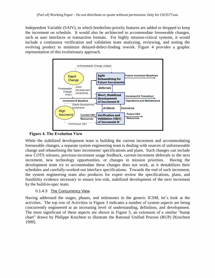
Independent Variable (SAIV), in which borderline-priority features are added or dropped to keep
the increment on schedule. It would also be architected to accommodate foreseeable changes,
such as user interfaces or transaction formats. For highly mission-critical systems, it would
include a continuous verification and validation team analyzing, reviewing, and testing the
evolving product to minimize delayed-defect-finding rework. Figure 4 provides a graphic
representation of this evolutionary approach.
Figure 4. The Evolution View
While the stabilized development team is building the current increment and accommodating
foreseeable changes, a separate system engineering team is dealing with sources of unforeseeable
change and rebaselining the later increments' specifications and plans. Such changes can include
new COTS releases, previous-increment usage feedback, current-increment deferrals to the next
increment, new technology opportunities, or changes in mission priorities. Having the
development team try to accommodate these changes does not work, as it destabilizes their
schedules and carefully-worked-out interface specifications. Towards the end of each increment,
the system engineering team also produces for expert review the specifications, plans, and
feasibility evidence necessary to ensure low-risk, stabilized development of the next increment
by the build-to-spec team.
0.1.4.3 The Concurrency View
Having addressed the stages, phases, and milestones in the generic ICSM, let’s look at the
activities. The top row of Activities in Figure 3 indicates a number of system aspects are being
concurrently engineered at an increasing level of understanding, definition, and development.
The most significant of these aspects are shown in Figure 5, an extension of a similar “hump
chart” drawn by Philippe Kruchten to illustrate the Rational Unified Process (RUP) [Kruchten
1999].

(Part of) Working Paper – Do not distribute or quote without permission. Only for CSCI577use.
As with the RUP version,
this is a conceptual
illustration, not a result of
some complex, data-
driven analysis. The
magnitude and shape of
the levels of effort are
risk-driven and will
almost certainly vary
from project to project. In
particular, they are likely
to have mini
risk/opportunity-driven
peaks and valleys, rather
than the smooth curves
shown for simplicity in
Figure 5. For example, in
the Exploration column,
although system scoping
is the primary objective of
the Exploration phase,
doing it well involves a
considerable amount of
activity in understanding
needs, envisioning
opportunities, identifying
and reconciling
stakeholder goals and
objectives, architecting
solutions, life cycle
planning, evaluating
alternatives, and
negotiating stakeholder
commitments.
Alternative descriptions: ICSM Metaphors
Playing the Odds
A simple metaphor to help understand the ICSM is to compare the ICSM to incremental-commitment gambling games such as Poker or Blackjack, rather than to single-commitment gambling games such as Roulette. Many system development projects operate like Roulette, in which a full set of requirements is specified up front, the full set of resources is committed to an essentially fixed-price contract, and one waits to see if the bet was a good one or not. The ICSM is more like Poker or Blackjack, in that one places an increasing series of bets to see whether the prospects of a win are good or not, and decides whether or not to continue betting based on better information about the prospects of success.
Life Together
The major ICSM life cycle milestone decision points work well as common commitment points across a variety of process model variants because they reflect similar commitment points during one’s lifetime. The Exploration Commitment Review milestone is the equivalent of investing time in going out on dates. The Valuation Commitment Review is the decision point at which you and a partner decide to go steady, investing some of your degrees of freedom in exploring the prospects of a more serious commitment. The Foundations Commitment Review is where the man invests in an engagement ring and the woman decides to say “yes” to a “Will you marry me?” question, but it is not yet an “until death do us part” commitment. That happens at the Development Commitment Review, which is the equivalent of getting married. As in life, if you marry your system architecture and plans in haste, you and your stakeholders will repent at leisure (if, in Internet time, any leisure time is available). The Operations Commitment Review constitutes an even larger commitment. It is the equivalent of having your first child, with all the associated commitments of care and feeding of a legacy system.
As with most metaphors, the correspondence of these decision points is not perfect. But the analogies of failure are pertinent: prematurely committing to infeasible requirements and spending lots of resources to create a failed outcome is similar to out-of-sequence life experiences such as dating, creating a child, getting married, and then finding that you can’t live with each other.

(Part of) Working Paper – Do not distribute or quote without permission. Only for CSCI577use.
Levels of activity
Activity category
System
Envisioning opportunities
System scoping
Understanding needs
Goals/objectivesRequirements
Architecting and designingsolutions a. system
b. human
c. hardware
d. software
Life-cycle planning
Feasibility Evidence
Negotiating commitments
Development and evolution
Monitoring and control
Operations and retirement
Organization capabilityimprovement
Explor
ation
Valuati
on
Found
ation
s
Develo
pmen
t1
Found
ation
s2
Opera
tions
& Pro
ducti
on1 (
O&P)1
Develo
pmen
t2
Found
ation
s3
VCR FCR DCR1OCR1
DCR2ECR
Stage I: Incremental DefinitionStage II: Incremental Development,
Operations & Production
ICSM Anchor Points
ICSM Lifecycle Phases
...
...
OC = Operational Capability ECR = Exploration Commitment Review VCR = Valuation Commitment Review
FCR = Foundations Commitment DCRn = Development Commitment Reviewn OCRn = Operations Commitment Reviewn
Figure 5. ICSM Concurrency View
0.1.4.4 How is All This Concurrent Engineering Synchronized and Stabilized?
The evidence-based anchor point milestone reviews are the mechanisms used in the ICSM to
manage the concurrency at the end of each phase. Each of these anchor point milestone reviews,
labeled at the top of Figure 5, is focused on evidence - developer-produced and independent-
expert reviewed - instead of typical briefings, assertions and assumptions. This provides accurate
information to help the key stakeholders determine the next level of commitment.
The review processes and use of independent experts are based on the highly successful AT&T
Architecture Review Board procedures described in [Maranzano 2005]. Figure 6 shows the
content of the Feasibility Evidence Description, the focus of each of the concurrency
stabilization reviews: Exploration Commitment Review (ECR), Valuation Commitment Review
(VCR), Foundations Commitment Review (FCR), and the Development Commitment Review
(DCR).

(Part of) Working Paper – Do not distribute or quote without permission. Only for CSCI577use.
Feasibility Evidence Description Content Evidence provided by developer and validated by independent experts that if the system is built to
the specified architecture, it will:
– Satisfy the requirements: capability, interfaces, level of service, and evolution
– Support the operational concept
– Be buildable within the budgets and schedules in the plan
– Generate a viable return on investment
– Generate satisfactory outcomes for all of the success-critical stakeholders
– Resolve all major risks by treating shortfalls in evidence as risks and covering
them by risk management plans
– Serve as basis for stakeholders’ commitment to proceed
The Operations Commitment Review (OCR) is different, in that it addresses the often much
higher operational risks of fielding an inadequate system. In general, stakeholders will
experience a factor of two-to-ten increase in commitment level in going through the sequence of
ECR to DCR milestones, but the increase in going from DCR to OCR can be much higher, as
can be the increase in going from DCR to the Production Commitment Review (PCR). These
commitment levels are based on typical cost profiles across the various stages of the acquisition
life-cycle. The OCR focuses on evidence of the adequacy of plans and preparations with respect
to hardware, software, personnel, facilities, and operational procedures, along with plans,
budgets, and schedules for fielding and operations.
Figure 6. Feasibility Evidence Description Content