The Inchworm Robot: A Multi-Functional System - MIT Computer
17
Autonomous Robots 8, 53–69 (2000) c 2000 Kluwer Academic Publishers. Printed in The Netherlands. The Inchworm Robot: A Multi-Functional System KEITH KOTAY AND DANIELA RUS Dartmouth Robotics Laboratory, Department of Computer Science, Dartmouth, Hanover, NH 03755 [email protected] [email protected] Abstract. We wish for robots to manipulate objects and move flexibly in three-dimensional spaces. We describe a robot that can move on a web of surfaces oriented around arbitrary directions in three-space and a set of control algorithms that implements motion in three-dimensions. The robot can manipulate objects in three dimensions while moving, by using the same set of physical resources and control algorithms. This robot is an inchworm-like robot with a simple, modular, and flexible design. Finally, we discuss our experiments. Keywords: inchworm robot, three-dimensional navigation, three-dimensional manipulation, minimalism 1. Introduction We wish for robots to navigate and manipulate objects flexibly and autonomously in three-dimensional envi- ronments, regardless of the presence, absence or direc- tion of gravity. Such robots must have the ability to propel themselves along any direction in three-space in a controlled way. Consider a task in which a robot is to climb up a complicated structure such as the Eiffel Tower, for inspection. The Eiffel tower is made of a web of metal bars. The bars are almost flat, they have varying lengths and directions, and they are oriented arbitrarily in three-space. A robot executing this task requires several skills: the robot should be able to climb vertically, the robot should be able to move inverted, it should be able to travel on arbitrarily oriented surfaces and avoid obstacles, and it should be able to make tran- sitions between adjacent surfaces (bars). We wish to do this task with an autonomous robot. We can view this task as a navigation problem in a three-dimensional space. The objects in this space are near-flat (planar or smooth with shallow curvatures) and they vary in size and orientation. The robot does not have geomet- rical models of the shape, nor mechanical models of their frictional properties. Furthermore, the robot does not assume anything about the size of the gravitational constant or about the direction of gravity. We assume however that the objects in the world are ferrous, so that the robot can use magnetic forces to attach to them. (We discuss alternatives to electromagnets as an attachment mechanism in Section 3.1.) Example worlds include the Eiffel tower, space stations, ships, metal bridges, radio towers, skyscrapers, nuclear reactors. Example applications for a robot endowed with the skill to nav- igate on such objects are inspection, fire-fighting, con- struction and repair tasks. In this paper we describe the Inchworm robot we have designed and built as an experimental platform for algorithms for three-dimensional navigation and manipulation. The Inchworm is a light robot designed with a minimalist philosophy (Donald et al., 1997a): we looked for the simplest mechanical and control de- sign that would support three dimensional locomotion. Minimalism (Donald et al., 1997a) provides an inter- esting framework for reducing the complexity of robot algorithms. A minimalist algorithm for task A that does not use resource B proves that B is inessential to the information structure of task A. In designing this robot we drew inspiration from biology. We studied the motions of inchworm cater- pillars. Inchworms (also called loopers) move with a looping movement in which the anterior legs and posterior legs are alternately made fast and released (Opler, 1994). The strong grip allows inchworms to attach themselves to arbitrarily oriented objects. The alternation of fastening enables a propelling motion.
Transcript of The Inchworm Robot: A Multi-Functional System - MIT Computer
Autonomous Robots 8, 53–69 (2000)c© 2000 Kluwer Academic Publishers. Printed in The Netherlands.
The Inchworm Robot: A Multi-Functional System
KEITH KOTAY AND DANIELA RUSDartmouth Robotics Laboratory, Department of Computer Science, Dartmouth, Hanover, NH 03755
Abstract. We wish for robots to manipulate objects and move flexibly in three-dimensional spaces. We describea robot that can move on a web of surfaces oriented around arbitrary directions in three-space and a set of controlalgorithms that implements motion in three-dimensions. The robot can manipulate objects in three dimensions whilemoving, by using the same set of physical resources and control algorithms. This robot is an inchworm-like robotwith a simple, modular, and flexible design. Finally, we discuss our experiments.
Keywords: inchworm robot, three-dimensional navigation, three-dimensional manipulation, minimalism
1. Introduction
We wish for robots to navigate and manipulate objectsflexibly and autonomously in three-dimensional envi-ronments, regardless of the presence, absence or direc-tion of gravity. Such robots must have the ability topropel themselves along any direction in three-spacein a controlled way. Consider a task in which a robot isto climb up a complicated structure such as the EiffelTower, for inspection. The Eiffel tower is made of aweb of metal bars. The bars are almost flat, they havevarying lengths and directions, and they are orientedarbitrarily in three-space. A robot executing this taskrequires several skills: the robot should be able to climbvertically, the robot should be able to move inverted, itshould be able to travel on arbitrarily oriented surfacesand avoid obstacles, and it should be able to make tran-sitions between adjacent surfaces (bars). We wish todo this task with an autonomous robot. We can viewthis task as a navigation problem in a three-dimensionalspace. The objects in this space are near-flat (planaror smooth with shallow curvatures) and they vary insize and orientation. The robot does not have geomet-rical models of the shape, nor mechanical models oftheir frictional properties. Furthermore, the robot doesnot assume anything about the size of the gravitationalconstant or about the direction of gravity. We assumehowever that the objects in the world are ferrous, so that
the robot can use magnetic forces to attach to them. (Wediscuss alternatives to electromagnets as an attachmentmechanism in Section 3.1.) Example worlds includethe Eiffel tower, space stations, ships, metal bridges,radio towers, skyscrapers, nuclear reactors. Exampleapplications for a robot endowed with the skill to nav-igate on such objects are inspection, fire-fighting, con-struction and repair tasks.
In this paper we describe the Inchworm robot wehave designed and built as an experimental platformfor algorithms for three-dimensional navigation andmanipulation. The Inchworm is a light robot designedwith a minimalist philosophy (Donald et al., 1997a):we looked for the simplest mechanical and control de-sign that would support three dimensional locomotion.Minimalism (Donald et al., 1997a) provides an inter-esting framework for reducing the complexity of robotalgorithms. A minimalist algorithm for task A that doesnot use resource B proves that B is inessential to theinformation structure of task A.
In designing this robot we drew inspiration frombiology. We studied the motions of inchworm cater-pillars. Inchworms (also called loopers) move witha looping movement in which the anterior legs andposterior legs are alternately made fast and released(Opler, 1994). The strong grip allows inchworms toattach themselves to arbitrarily oriented objects. Thealternation of fastening enables a propelling motion.

54 Kotay and Rus
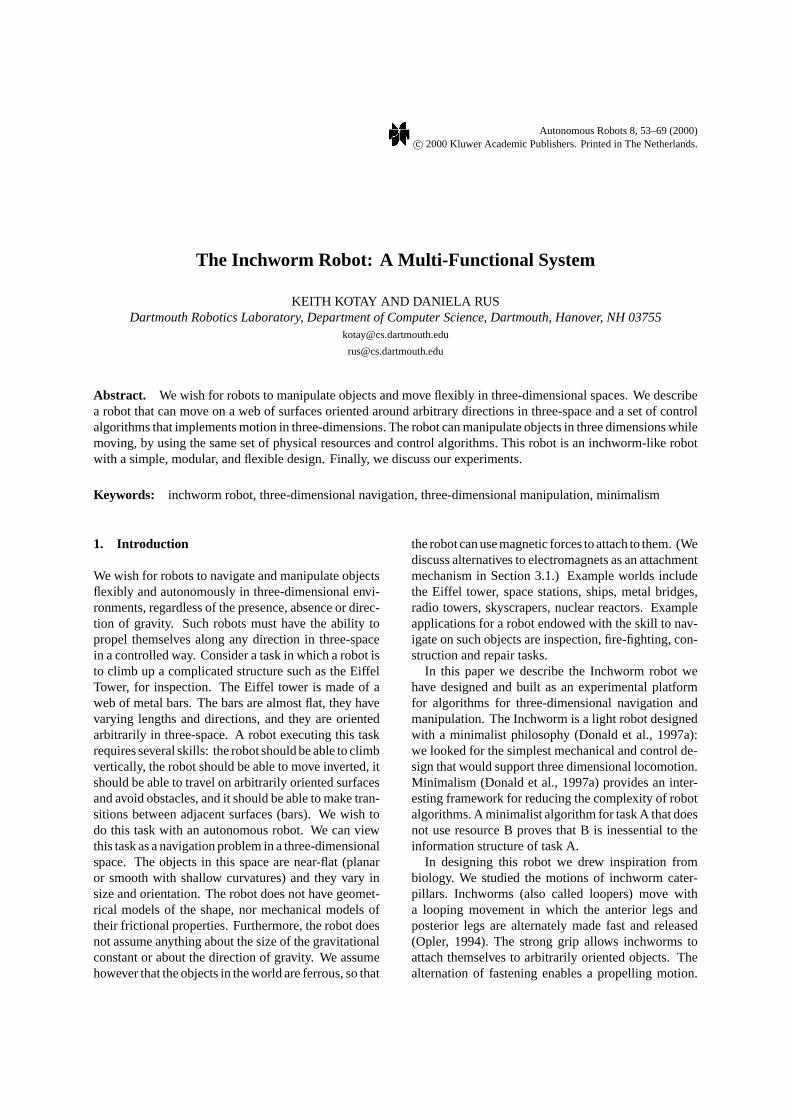
Figure 1. The Inchworm robot. The body of robot consists offour links. The first and last link of the robot comprise the feet.Each foot has two 1-inch electromagnets attached to it. The robothas one front IR sensor and a pair (IR sensor, contact switch fortouch sensing) attached to each electromagnet. The robot has threeactuators attached to the three joints visible in the plane of the image.A fourth actuator attached to the back foot allows the robot to pivotin and out of the plane of the image.
This simple strategy gives inchworms the mobility tomove stably on arbitrarily oriented surfaces.
We have engineered an Inchworm robot that is alight linear structure made of four links. The end linksare the robot’s twofeet (see Fig. 1). Electromagnetsplaced on the feet allow the robot to attach to arbitrarilyoriented surfaces, much like the loopers. Similarly, therobot alternates current to the two electromagnetic feetto simulate the inchworm propelling motion.
The Inchworm robot supports anO(1) greedy navi-gation strategy based on the idea of climbing over theobstacles to reach the goal rather than the usual wayof searching for paths around obstacles. The Inch-worm robot uses a small set of task-level primitives formoving along planes of arbitrary orientations and formaking transitions between such planes. These task-level primitives can be composed to generate on-linenavigation algorithms in three dimensions and manip-ulation algorithms. Thus, the Inchworm belongs tothe class ofmobipulatorrobots (Mason et al., 1999,to appear; Nilsson, 1984; Pai et al., 1994; Donaldet al., 1997; Xu et al., 1994), which are designed toexplore the connections between locomotion and ma-nipulation. While several other papers have examinedthe connection between locomotion and manipulation
(Mason et al., 1999, to appear; Nilsson, 1984; Pai et al.,1994; Donald et al., 1997a; Xu et al., 1994), this robotis different in that it treats manipulation and locomo-tion identically at the control level. All locomotion andmanipulation algorithms are composed from the sameset of task-level primitives.
In our lab, we built two Inchworm robots. Our sim-ple and modular design is lean in sensors and actuatorsbut is extensible: right now each robot consists of fouridentical links connected by a simple joint. The robotis equipped with a camera, 5 IR proximity sensors and4 discrete touch sensors attached to the feet, and movescompliantly. This design is extensible to any numbern of links. We advocate an extensible minimalist ap-proach to robot architectures for two reasons. First,since the size of an Inchworm step is proportional tothe total length of the robot, an extensible architectureimpacts the speed and efficiency of navigation. Thisis particularly suited to applications where there is nogravity, as supporting the weight of a robot on mag-nets no longer becomes an issue. Second, extensiblerobots have increased functionality. For example, weare planning on building four more Inchworm robotsand combining them into a six-legged walker. Sucha robot will be able to travel on non-ferrous and non-smooth terrains.
The Inchworm robot can propel itself on arbitrarilyoriented surfaces in the absence of geometric mod-els. Its motions are compliantly controlled on-line.The control algorithms are simple, compliant, on-line, adaptive, and reliable. In our lab, the Inchwormwalked hundreds of steps over filing cabinets, doors,and closets. The robot also walked up a fire escapeoutdoors.
The Inchworm robot can also manipulate objectswhile navigating over three dimensional surfaces. Thebasic manipulation skills we have developed are push-ing an object (moving on a flat surface or climbing onan incline) and pulling an object on a flat surface. Inour lab the robot performed these operations with greatreliability. The robot was also capable of transitioningbetween a pure navigation mode to a navigation andmanipulation mode. In this paper we show how to ac-complish this using the same basic control and designparadigms to enable both manipulation and locomo-tion. This is a basic form of multi-functional robotics,in which, as in biological systems, the same set of phys-ical resources can be used in a different manner, for dif-ferent tasks, by employing different control pathwaysor control algorithms.
The Inchworm Robot 55
2. Related Work
Our work draws on previous experiences with nav-igation algorithms (Latombe, 1991), designing bio-logically-inspired robots, and designing minimalistrobot systems (Donald et al., 1997a, 1997b).
Related work on biologically-inspired robots in-cludes Brooks (1989), Leventon (1993), Hirose et al.(1991), Fernworn and Stacey (1996), Desai et al.(1995). Brooks (1989) proposes insect intelligences.Leventon (1993) describes the design by Kerley of acaterpillar robot capable of a crawling movement simi-lar to the horizontal gait of our robot. The robot is alsocapable of climbing, but its flexibility is limited, mak-ing obstacle avoidance difficult. Fernworn (1995) de-scribes an inchworm robot capable of linear motions onhorizontal surfaces. Burleigh Instruments developedand patented an Inchworm Motor whose funtionalityresembles the movement of an inchworm caterpillar(see http://www.burleigh.com/Pages/inchtech.htm fordetails).
Related work on climbing robots include Madhaniand Dubowsky (1992), Neubauer (1994), Hirose et al.(1991), Gradetsky and Rachkov (1990), Carrara andde Paulis (1989), Nishi (1992), Chernousko (1990),Xu et al. (1994). Dubowsky (Madhani and Dubowsky,1992) describes a three-legged robot that climbs be-tween two ladders. Nishi (1992) describes a bipedwalking robot configured as a pendulum that uses asuction device for attachment and is capable of lin-ear motions and surface transitions. Hirose (Hiroseet al., 1991; Nagakubo and Hirose, 1994) describes aquadruped robot that uses suction cups for attachmentand can climb on straight surfaces (vertically and hor-izontally) and make transitions between surfaces withjoint angles of 90 degrees. This robot is much heavierthan ours (99 pounds vs. 1 pound). Xu et al. (Xu et al.,1994; Xu and Ueno, 1994) describe an inchworm-likerobot that uses grippers as attachments to move alonga space station truss. Our robot is different than theprevious climbing robots in that it is much smaller,lighter, uses less sensing, needs less workspace to op-erate and it can handle web structures, as well as solidwalls. However, our robot requires a ferrous surfacewhile the robots proposed in Nishi (1992) and Hiroseet al. (1991) use suction cups and the robot proposed inXu et al. (1994) use grippers—thus these other robotsdo not have material dependencies. Finally, the robots(Nishi, 1992; Hirose et al., 1991) depend on smoothsurfaces, while ours can handle porous surfaces.
Related work on the exploration of the connectionsbetween locomotion and manipulation include Masonet al. (1999, to appear), Nilsson (1984), Pai et al.(1994), Donald et al. (1997b), Xu et al. (1994). In Rusand Kotay (1999), a modular extensible robot architec-ture that support multiple modalities of locomotion isdescribed. We were inspired by the control and kine-matic analysis of Kelly and Murray (1994), Chen et al.(1994), Chirikjian and Burdick (1991) in the designand kinematic analysis of our system.
3. The Inchworm Robot
3.1. The Mechanical Components
The Inchworm is a biologically-inspired minimalistrobot, designed to imitate the movements of the inch-worm caterpillar. This functionality was achieved bycreating a light, linear structure made of four sections.The sections are linked with three joints providing threedegrees of freedom (see Fig. 1). These joints allow theInchworm to extend and flex. The first and fourth sec-tions are thefeetof the Inchworm. These sections con-tain the attachment mechanisms, equivalent to the legsand protolegs of the inchworm caterpillar, which allowthe Inchworm to adhere to the surface it is traversingand provide the anchoring force needed to support theInchworm walking motion. A fourth degree of freedomis provided by a pivot joint which allows the body ofthe Inchworm to rotate relative to the attachment mech-anism of the rear foot. This allows the robot to turn.The actuators for the joints are servomotors (Airtronics94739 Proportional Retract Servo) designed for use inradio controlled aircraft. The 94739 servo weighs 50grams and produces 5.3 kg cm of torque. This hightorque-to-weight ratio is essential to support the fullrange of motion (especially the surface-to-surface tran-sitions) we wish the robot to have.
The weight of the Inchworm is 566 grams. Whenfully extended, the length of the robot is 330 millime-ters and its height is 80 millimeters. When fully con-tracted, the length of the robot is 175 millimeters andits height is 160 millimeters. The speed of the robot is0.75 meters/minute.
The attachment mechanism of the robot is com-prised of electromagnets. There are two 12-volt electro-magnets per Inchworm foot, arranged in-line with thebody of the Inchworm. These electromagnets provideenough force to securely anchor a foot and support theweight of the robot when the other foot is completely
56 Kotay and Rus
extended. This enables our robot to utilize its en-tire range of motion. We chose electromagnets be-cause they are easy to use and provide a large amountof attachment force in a small package. However,this choice restricts the motion of the robot to steelsurfaces. The modular design of the robot makes iteasy to replace the electromagnetic modules (mechan-ical, electronic, and control) with modules that utilizesuction cups or grippers.
The Inchworm has three types of sensors: touch sen-sors, infrared proximity sensors, and a small camera.The touch sensors are Omron model EE-SA105 pho-totransistor optical switches with spring actuator. Twoof these sensors are mounted on each foot of the Inch-worm, one in front of the forward electromagnet andone behind the rear electromagnet. The touch sensorsare used to establish firm contact of the electromagnetswith the surface being traversed. The touch sensorsalso are used to indicate error conditions such as con-tact with a surface when it is not expected. The infraredproximity sensors are Omron model EE-SF5 reflectivephotomicrosensors. These sensors are used to imple-ment compliant movements along a surface. Five in-frared proximity sensors are used on the Inchworm,four mounted adjacent to the touch sensors orienteddownward in order to monitor the surface, and onemounted on the front of the Inchworm facing forward.The camera is a small 1.125 inch monochrome camerawith a 6.5 mm lens. The camera is mounted on thefront foot of the robot and it points forward.
The power source for the Inchworm consists of twolead-acid batteries. An 8-volt battery is used to powerthe servomotors and the electronics. The electromag-nets are powered by a 18-volt battery. The batteries arenot located on the body of the Inchworm due to weightconstraints. Thus, the current use of electromagnetspresents a limitation for using this robot on high struc-tures: the Inchworm Inchworm must be connected tothese components with a tether, which increases theweight of the system. We are currently exploring othermeans of powering this robot, for example with solarcells or a small gas-combustion engine.
3.2. The Electronic Components
Low-level hardware control of the Inchworm isachieved by an on-board 8-bit PIC16C73 microcon-troller. This microcontroller generates the pulse widthmodulation signals used to control the servomotors andalso reads the robot’s sensors. Higher-level control is
performed by a remote workstation which communi-cates with the microcontroller via a 38.4k baud se-rial link. This gives the Inchworm the properties ofa remote-brained system, as outlined in (Inaba, 1993).
The servomotors (e.g., the actuators) are controlledby varying the width of a positive electronic pulse be-tween 1 and 2 milliseconds in duration. This pulse mustbe repeated every 20 milliseconds. Each servo is con-trolled by a 9-bit value output by the PIC16C73 micro-controller. We use 308 different servo positions, whichresults in a rotational resolution of 0.85 degrees.
Electromagnet control is accomplished by a inte-grated circuit designed to switch inductive loads. A bi-nary value controls the state of the electromagnets oneach foot, yielding four possible states of energizationfor the Inchworm feet. Analog control of the electro-magnets was considered unnecessary for the initial de-sign; however there may be situations in which analogcontrol is useful.
One difficulty with using electromagnets is the resid-ual magnetism which develops in the steel to which theelectromagnets are attached. This residual magnetismgenerates a holding force after the current to the elec-tromagnets has been discontinued. The robot must beable to overcome this force to move the attached ap-pendage. A solution to this problem is to provide aburst of current in the opposite direction of that usedto attach the electromagnets to the surface. This burstof current generates a brief counter-electromagneticfield which removes the residual force. Our empiricaldata suggests that the Inchworm servos are powerfulenough to overcome the residual force, making addi-tional reverse-current circuitry unnecessary.
4. Control
The four degrees of freedom allow the Inchwormrobot to move compliantly on arbitrarily oriented three-dimensional surfaces and manipulate objects using alooping motion. In this section we describe a generalcontroller for the looping motion of the robot and wepresent the primitive control algorithms that can becomposed to implement navigation and manipulationgaits.
We start by observing that the configuration spaceof this robot is
SE(2)× S1(−π/2,π/2) × S1
(−π/2,π/2) × S1(−π/2,π/2).
Here,S1(−π/2,π/2) denotes a subset ofS1 defined for the
range of angles(−π/2, π/2). In the absence of inertial
The Inchworm Robot 57
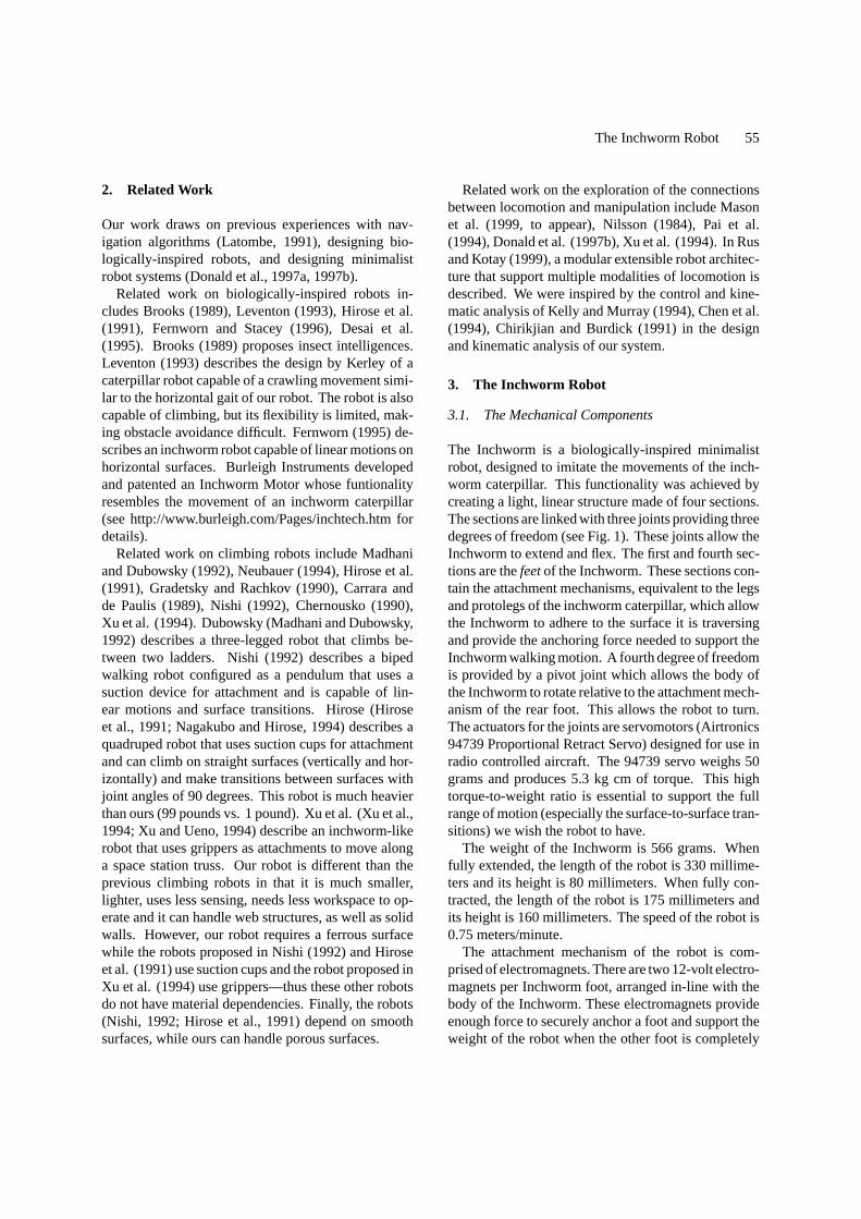
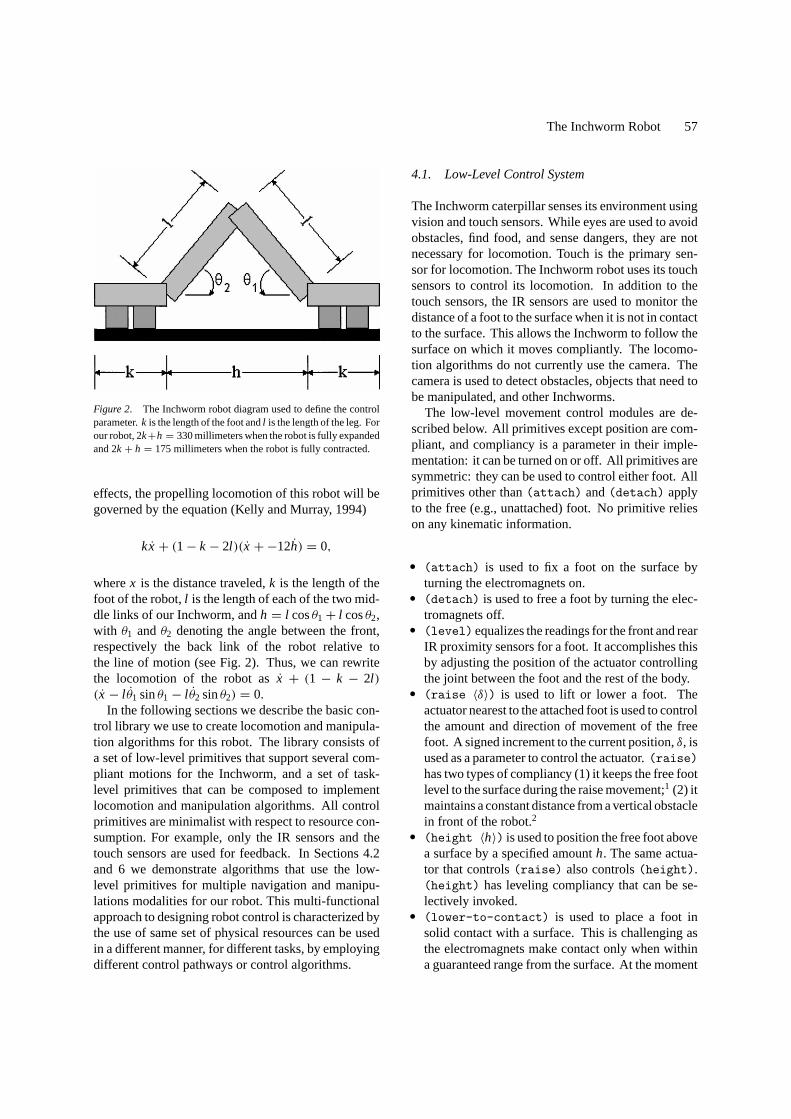
Figure 2. The Inchworm robot diagram used to define the controlparameter.k is the length of the foot andl is the length of the leg. Forour robot, 2k+h = 330 millimeters when the robot is fully expandedand 2k+ h = 175 millimeters when the robot is fully contracted.
effects, the propelling locomotion of this robot will begoverned by the equation (Kelly and Murray, 1994)
kx + (1− k− 2l )(x +−12h) = 0,
wherex is the distance traveled,k is the length of thefoot of the robot,l is the length of each of the two mid-dle links of our Inchworm, andh = l cosθ1+ l cosθ2,with θ1 andθ2 denoting the angle between the front,respectively the back link of the robot relative tothe line of motion (see Fig. 2). Thus, we can rewritethe locomotion of the robot asx + (1 − k − 2l )(x − l θ1 sinθ1− l θ2 sinθ2) = 0.
In the following sections we describe the basic con-trol library we use to create locomotion and manipula-tion algorithms for this robot. The library consists ofa set of low-level primitives that support several com-pliant motions for the Inchworm, and a set of task-level primitives that can be composed to implementlocomotion and manipulation algorithms. All controlprimitives are minimalist with respect to resource con-sumption. For example, only the IR sensors and thetouch sensors are used for feedback. In Sections 4.2and 6 we demonstrate algorithms that use the low-level primitives for multiple navigation and manipu-lations modalities for our robot. This multi-functionalapproach to designing robot control is characterized bythe use of same set of physical resources can be usedin a different manner, for different tasks, by employingdifferent control pathways or control algorithms.
4.1. Low-Level Control System
The Inchworm caterpillar senses its environment usingvision and touch sensors. While eyes are used to avoidobstacles, find food, and sense dangers, they are notnecessary for locomotion. Touch is the primary sen-sor for locomotion. The Inchworm robot uses its touchsensors to control its locomotion. In addition to thetouch sensors, the IR sensors are used to monitor thedistance of a foot to the surface when it is not in contactto the surface. This allows the Inchworm to follow thesurface on which it moves compliantly. The locomo-tion algorithms do not currently use the camera. Thecamera is used to detect obstacles, objects that need tobe manipulated, and other Inchworms.
The low-level movement control modules are de-scribed below. All primitives except position are com-pliant, and compliancy is a parameter in their imple-mentation: it can be turned on or off. All primitives aresymmetric: they can be used to control either foot. Allprimitives other than(attach) and(detach) applyto the free (e.g., unattached) foot. No primitive relieson any kinematic information.
r (attach) is used to fix a foot on the surface byturning the electromagnets on.r (detach) is used to free a foot by turning the elec-tromagnets off.r (level)equalizes the readings for the front and rearIR proximity sensors for a foot. It accomplishes thisby adjusting the position of the actuator controllingthe joint between the foot and the rest of the body.r (raise 〈δ〉) is used to lift or lower a foot. Theactuator nearest to the attached foot is used to controlthe amount and direction of movement of the freefoot. A signed increment to the current position,δ, isused as a parameter to control the actuator.(raise)has two types of compliancy (1) it keeps the free footlevel to the surface during the raise movement;1 (2) itmaintains a constant distance from a vertical obstaclein front of the robot.2r (height 〈h〉) is used to position the free foot abovea surface by a specified amounth. The same actua-tor that controls(raise) also controls(height).(height) has leveling compliancy that can be se-lectively invoked.r (lower-to-contact) is used to place a foot insolid contact with a surface. This is challenging asthe electromagnets make contact only when withina guaranteed range from the surface. At the moment

58 Kotay and Rus
this robot does not have force control to detect im-pediment, in case the foot attempts to penetrate a sur-face. We rely on the contact switches (touch sensors)to detect this case.(lower-to-contact) is a se-quential composition of(height) (to place the footin close proximity to the surface) and(raise −δ)that continues until one or both of the touch sensorsindicates that the foot has made contact with the sur-face. The motion terminates when both touch sen-sors record contact. When only one of the touchsensors is in contact, a search for the terminationcondition is implemented by rotating the foot.r (extend 〈r 〉) is used to increase or decrease thedistance between the feet. Ifr > 0, the center servoincreases the angle between the two middle sectionsof the body resulting in a separation of the feet.(ex-tend) uses(level) and(height) as subroutinesand it has simultaneous compliancy for the level andheight parameters. In normal operation,(extend)will maintain the initial height of the foot through-out the motion. It relies on the(level) primitive tokeep the foot level above the surface it is traversing.We have observed experimentally that Inchwormcomplies to variations in the surface slope and tran-sitions between surfaces of as much as 45 degreeswithin a single extending motion.r (position) is used to move the body of the robot toa specified relative location. This is a non-compliantprimitive, and it is only used when we have a guaran-tee that the path of the motion is through free space.
4.2. Task-Level Primitives
The Inchworm robot can navigate three dimensionalstructures and it can manipulate objects. The robot canpropel itself on arbitrarily oriented surfaces in an on-line fashion, in the absence of geometric models andindependent of the direction and magnitude of gravity.The robot can walk, climb, and walk inverted. Therobot can also make transitions between surfaces whosejoint angle is convex or concave. These motions are ob-tained by composing the low-level control primitives in
Figure 3. Illustration of the basic step movements. The two small arrows denote the foot which is connected to the environment. The largearrow denotes the direction of the next motion.
different ways. All motions are compliantly controlledon-line. The control algorithms are simple, compliant,adaptive, and reliable. We have implemented each ofthese skills as task-level operations. The rest of this sec-tion is devoted to describing the skills used for three-dimensional navigation.
4.2.1. Stepping. The simplest locomotion skill is the(step). A (step) consists of two phases, the exten-sion phase and the contraction phase. During the ex-tension phase, the rear foot is attached to the surface.An extension is accomplished by raising the front foot,extending it forward, and then lowering the foot untilit contacts the surface. At this point, the front foot isattached to the surface and the rear foot is detached.The contraction phase then occurs by raising the rearfoot, contracting the rear foot to bring it closer to thefront foot, and then lowering the foot until it contactsthe surface.
The control algorithm for(step) consists of ex-tending the front foot and then moving forward therear foot (see Fig. 3). We defined(step) as the fol-lowing sequential composition of the low-level controlprimitives described in Section 4.1:
(attach back-foot)(detach front-foot); move front
foot forward(raise l-compliance)(extend d l-compliance h-compliance)(attach front-foot)(detach back-foot); move back
foot forward(raise level-compliance)(extend −d l-compliance h-compliance)(lower-to-contact)(attach back-foot)(detach front-foot)
This algorithm is expressed in a reference frame withthe x-axis aligned with the current surface. The robotcan use this algorithm to translate on surfaces of ar-bitrary orientations. For example, Fig. 4 shows the
The Inchworm Robot 59
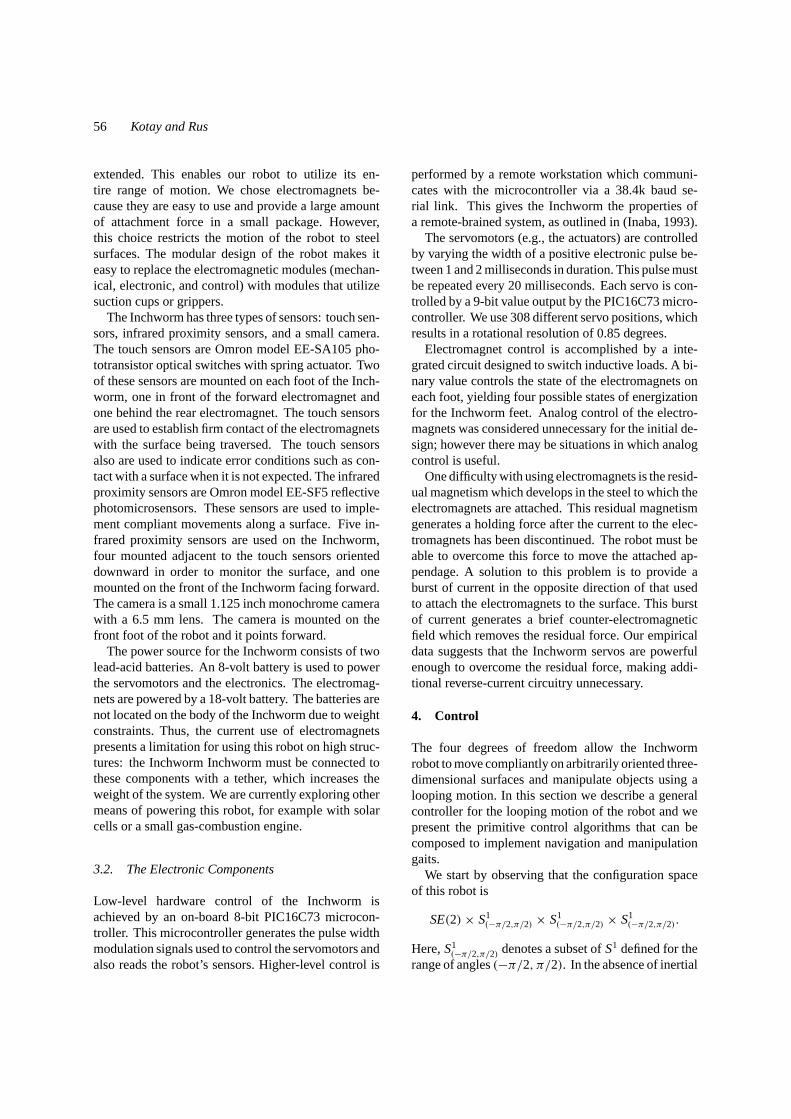
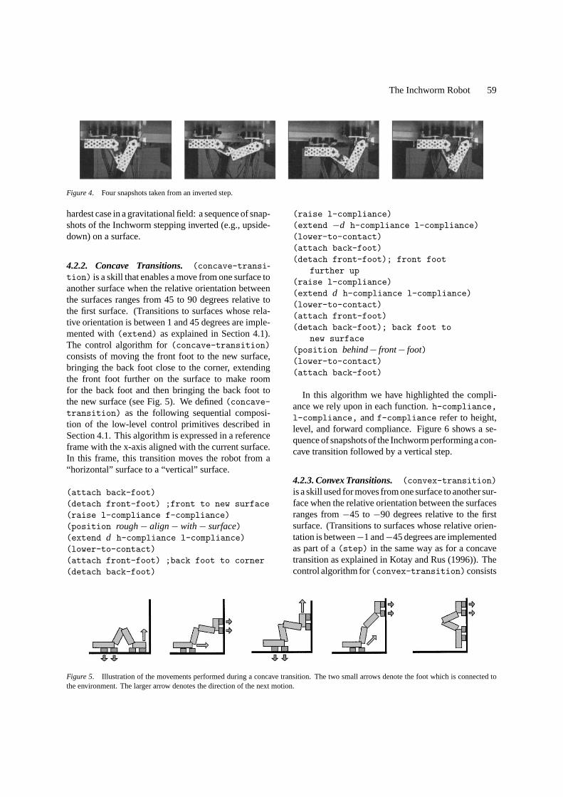
Figure 4. Four snapshots taken from an inverted step.
hardest case in a gravitational field: a sequence of snap-shots of the Inchworm stepping inverted (e.g., upside-down) on a surface.
4.2.2. Concave Transitions. (concave-transi-tion) is a skill that enables a move from one surface toanother surface when the relative orientation betweenthe surfaces ranges from 45 to 90 degrees relative tothe first surface. (Transitions to surfaces whose rela-tive orientation is between 1 and 45 degrees are imple-mented with(extend) as explained in Section 4.1).The control algorithm for(concave-transition)consists of moving the front foot to the new surface,bringing the back foot close to the corner, extendingthe front foot further on the surface to make roomfor the back foot and then bringing the back foot tothe new surface (see Fig. 5). We defined(concave-transition) as the following sequential composi-tion of the low-level control primitives described inSection 4.1. This algorithm is expressed in a referenceframe with the x-axis aligned with the current surface.In this frame, this transition moves the robot from a“horizontal” surface to a “vertical” surface.
(attach back-foot)(detach front-foot) ;front to new surface(raise l-compliance f-compliance)(position rough− align− with− surface)(extend d h-compliance l-compliance)(lower-to-contact)(attach front-foot) ;back foot to corner(detach back-foot)
Figure 5. Illustration of the movements performed during a concave transition. The two small arrows denote the foot which is connected tothe environment. The larger arrow denotes the direction of the next motion.
(raise l-compliance)(extend −d h-compliance l-compliance)(lower-to-contact)(attach back-foot)(detach front-foot); front foot
further up(raise l-compliance)(extend d h-compliance l-compliance)(lower-to-contact)(attach front-foot)(detach back-foot); back foot to
new surface(position behind− front− foot)(lower-to-contact)(attach back-foot)
In this algorithm we have highlighted the compli-ance we rely upon in each function.h-compliance,l-compliance, andf-compliance refer to height,level, and forward compliance. Figure 6 shows a se-quence of snapshots of the Inchworm performing a con-cave transition followed by a vertical step.
4.2.3. Convex Transitions. (convex-transition)is a skill used for moves from one surface to another sur-face when the relative orientation between the surfacesranges from−45 to−90 degrees relative to the firstsurface. (Transitions to surfaces whose relative orien-tation is between−1 and−45 degrees are implementedas part of a(step) in the same way as for a concavetransition as explained in Kotay and Rus (1996)). Thecontrol algorithm for(convex-transition)consists
60 Kotay and Rus
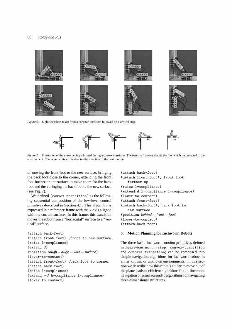
Figure 6. Eight snapshots taken from a concave transition followed by a vertical step.
Figure 7. Illustration of the movements performed during a convex transition. The two small arrows denote the foot which is connected to theenvironment. The larger white arrow denotes the direction of the next motion.
of moving the front foot to the new surface, bringingthe back foot close to the corner, extending the frontfoot further on the surface to make room for the backfoot and then bringing the back foot to the new surface(see Fig. 7).
We defined(convex-transition) as the follow-ing sequential composition of the low-level controlprimitives described in Section 4.1. This algorithm isexpressed in a reference frame with the x-axis alignedwith the current surface. In this frame, this transitionmoves the robot from a “horizontal” surface to a “ver-tical” surface.
(attach back-foot)(detach front-foot) ;front to new surface(raise l-compliance)(extend d)(position rough− align−with− surface)(lower-to-contact)(attach front-foot) ;back foot to corner(detach back-foot)(raise l-compliance)(extend −d h-compliance l-compliance)(lower-to-contact)
(attach back-foot)(detach front-foot); front foot
further up(raise l-compliance)(extend d h-compliance l-compliance)(lower-to-contact)(attach front-foot)(detach back-foot); back foot to
new surface(position behind− front− foot)(lower-to-contact)(attach back-foot)
5. Motion Planning for Inchworm Robots
The three basic Inchworm motion primitives definedin the previous section (step, convex-transitionand concave-transition) can be composed intosimple navigation algorithms for Inchworm robots ineither known, or unknown environments. In this sec-tion we describe how this robot’s ability to move out ofthe plane leads to efficient algorithms for on-line robotnavigation on a surface and to algorithms for navigatingthree-dimensional structures.

The Inchworm Robot 61
5.1. Motion Planning on Three-DimensionalSteel Web Structures
Suppose the environment of the Inchworm is a three-dimensional structure such as a bridge, a tower, or thescaffolding of a building. Wheel-based mobile robotscan not navignate such structures. Inchworm robots,however, can move regardless of the direction of grav-itation. The Inchworm robot can compose its abil-ity to step in a plane of arbitrary orientations,turnto change movement direction in the place, and makesurface transitions between planes to move. Thus, theInchworm robot can function as a navigator of three-dimensional surfaces.
Due to the current use of magnets as the attachmentmechanism, the robot in currently restricted tosteelsurfaces. However, we do not consider this to be aloss of generality because it is possible to replace themagnets with suction cups to implement attachment toother materials.
The size and configuration space of the robot (whichmay be limited by the actuator used at the joint) addssome limitations to the geometry of the structures thatcan be traversed by this robot. Figure 8 illustrates thelimit cases for concave and convex transitions. Con-sider the notation in Figs. 2 and 8. Using the law ofsines and the law of cosines, it is easy to derive anequation of
sinα >l sinθ1√
l 2+ k2+ 2lk cosθ1
for the concave anglesα in the environment that permitthe robot to make concave transitions. Similarly, usingbasic geometric facts on angles, it is easy to derive anequation of
2π − β, whereβ > π − 2θ1− 2θ2
for the convex angles 2π − β in the environment thatpermit the robot to make convex transitions. The lower
Figure 8. Illustration of the environment constraints. The leftmost image shows the Inchworm robot in a typical concave angle transition.The second image show the Inchworm robot in a limit case for performing concave transitions: the robot is stuck, due to the geometry of theenvironment. The third image shows the Inchworm robot in a typical convex angle transition. The fourth image shows the Inchworm robot in alimit case for performing convex surface transitions: the actuators of the robot may not be able to exert the torque necessary to reach the wall.
bound forα is obtained by setting the values ofθ1 andθ2 so that the robot is fully compressed. The upperbound for 2π − β is obtained by setting the values ofθ1 andθ2 to the maximum configuration supported bythe robot actuators. For the current implementation ofthe Inchworm robot described in this paper the concaveangles can be at most sinα = l (
√3/2)√
l 2+k2+lkand the convex
angles can be at most 5π/3.For environments that satisfy the concave and con-
vex angle constraints, we can employ classical off-linemotion planning algorithms (Latombe, 1991) to com-pute the robot’s path from start to goal, or we can usealgorithms that enable the robot to travel along all sur-faces in the environment for inspection purposes.
5.2. On-Line Navigation
In this section we discuss navigation issues for Inch-worm robots in the absence of maps. For example, wemay consider a factory floor where dynamic obstaclesmake it impossible to supply the robot with an accuratemap. The model for this problem is an Inchworm robotthat starts at a known location and is to find its way toa goal location, identifiable by a beacon.
A simple strategy, such as the right hand rule, or theon-line navigation algorithms proposed by Lumelsky(1987), may be employed to find a path to the goal.However, because Inchworm robots have the abilityto move out of plane, we propose a simpler algorithmfor this problem. The basic idea is to move the robotgreedily in the direction of the goal. When an obsta-cle is reached, instead of going around the obstacle,which is the technique employed by robots confined tomove in the plane (for example wheel-based robots),Inchworm robots can simply climb over the obstacles,maintaining their original heading. The algorithm de-scribed in Fig. 9 summarizes this intuition.
Theorem 1. Suppose an Inchworm robot has to travelfrom an initial location S to a goal location G in an
62 Kotay and Rus
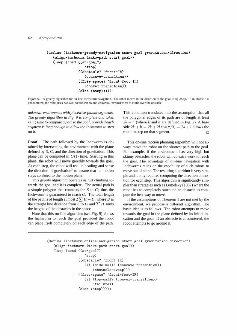
Figure 9. A greedy algorithm for on-line Inchworm navigation. The robot moves in the direction of the goal usingstep. If an obstacle isencountered, the robot usesconvex-transition andconcave-transition to climb over the obstacle.
unknown environment with piecewise-planar segments.The greedy algorithm in Fig.9 is complete and takesO(1) time to compute a path to the goal, provided eachsegment is long enough to allow the Inchworm to stepon it.
Proof: The path followed by the Inchworm is ob-tained by intersecting the environment with the planedefined byS, G, and the direction of gravitation. Thisplane can be computed inO(1) time. Starting in thisplane, the robot will move greedily towards the goal.At each step, the robot will use its heading and sensethe direction of gravitation3 to ensure that its motionstays confined to the motion plane.
This greedy algorithm operates as hill climbing to-wards the goal and it is complete. The actual path isa simple polygon that connects theS to G; thus theInchworm is guaranteed to reachG. The total lengthof the path is of length at most 2
∑H +D, whereD is
the straight line distance fromS to G and∑
H sumsthe heights of the obstacles in the space.
Note that this on-line algorithm (see Fig. 9) allowsthe Inchworm to reach the goal provided the robotcan place itself completely on each edge of the path.
(define (inchworm-online-navigation start goal gravitation-direction)(align-inchworm (make-path start goal))(loop (cond ((at-goal?)
’stop)((obstacle? ’front-IR)
(if (side-wall? (concave-transition))(obstacle-sweep)))
((free-space? ’front-foot-IR)(if (top-wall? (convex-transition))
’failure))(else (step)))))
This condition translates into the assumption that allthe polygonal edges of its path are of length at least2k + h (wherek andh are defined in Fig. 2). A baseside 2k + h = 2k + 2l cos(π/3) = 2k + l allows therobot to step on that segment. 2
This on-line motion planning algorithm will not al-ways move the robot on the shortest path to the goal.For example, if the environment has very high butskinny obstacles, the robot will do extra work to reachthe goal. The advantage of on-line navigation withInchworms relies on the capability of such robots tomove out of plane. The resulting algorithm is very sim-ple and it only requires computing the direction of mo-tion for each step. This algorithm is significantly sim-pler than strategies such as Lumelsky (1987) where therobot has to completely surround an obstacle to com-pute the best way to move.
If the assumptions of Theorem 1 are not met by theenvironment, we propose a different algorithm. Thebasic idea is as follows. The robot attempts to movetowards the goal in the plane defined by its initial lo-cation and the goal. If an obstacle is encountered, therobot attempts to go around it.
The Inchworm Robot 63
The Inchworm uses its rotational degree of freedomon the back foot to scan the space in front of it. Thescanning operation is done with the IR sensors, whichhave a limited visibility range. Thus, if the robot de-tects no change in the nature of the surface, it contin-ues with a step. If the robot detects an obstacle sur-face it examines the height of the surface to decidedwhether it is a wall or an obstacle. If the surface islong enough to permit a concave transition, the robotmoves in that configuration and repeats. If the surfaceis a small obstacle, the(obstacle-sweep) algorithmis executed to go around. Finally, if the robot detects anempty space it examines the length of the wall to deter-mine whether a convex transition can be performed. Ifthe top surface is too small for a convex transition, therobot has the choice of returning’failure or backingup.
The (obstacle-sweep) function is employed tocreate a path to the goal. The robot finds the most op-timal corner, proceeds to the most optimal corner, andrepeats. This algorithm uses the IR sensors to detect ob-stacles and estimate the distance to the obstacle corners.The robot effectively constructs a tree that correspnodsto the topology of the environment (that is, branches inthe tree correspond to paths and preserve the relativeorder of the paths in the physical environment). Thenext point in the tree is chosen by optimizing the direc-tion and the area the Inchworm wishes to travel throughnext. If there is a straight path to the goal, it is detectedby the sweep and the Inchworm heads straight towardthe goal until obstacles are detected at some thresholddistance. Otherwise, the Inchworm chooses the nextpoint in the tree that minimizes the path to the goal.The process continues until the robot recognizes thegoal by using a beacon or odometry.
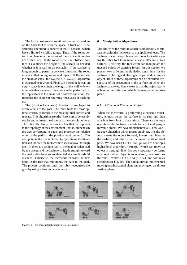
Figure 10. Six snapshots taken from a sweep sequence
6. Manipulation Algorithms
The ability of the robot to attach itself securely to sur-faces enables the Inchworm to manipulate objects. TheInchworm can grasp objects with one foot while us-ing the other foot to maintain a stable attachment to asurface. This way, the Inchworm can manipulate thegrasped object by exerting forces. In this section wepresent two different manipulation algorithms for theInchworm: lifting and placing an object and pulling anobject. Both of these algorithms can be executed irre-spective of the orientation of the surface on which theInchworm moves. One caveat is that the object has toadhere to the surface on which the manipulation takesplace.
6.1. Lifting and Placing an Object
When the Inchworm is performing a concave transi-tion, it must detect the surface in its path and thenattach its front foot to that surface. These are the sameoperations the Inchworm needs to detect and grasp amovable object. We have implemented a(lift-and-place) algorithm which grasps an object, lifts the ob-ject, moves the object forward, lowers the object tothe surface, and returns the Inchworm to its originalpose. We have used(lift-and-place) to develop ahigher-level algorithm,(sweep), which can move anobject in a straight line.(sweep) repeatedly performsa(step) until an object is encountered, then positionsthe robot, invokes(lift-and-place), and continuesstepping (see Fig. 10). The operation was implementedmoving on a horizontal plane and moving on an almostvertical plane.

64 Kotay and Rus
When an object is detected by the forward IR sensorduring astep movement, the(step) is terminatedand the Inchworm is positioned to perform a grasp. A(raise) movement with forward compliance is thenused to lift the front foot while maintaining a constantdistance to the object. Then a(position) motion isperformed to align the bottom of the front foot with theobject, followed by an(extend) motion which ter-minates on the detection of free space by the forward,downward-pointing IR sensor on the front foot, signi-fying that the front foot is near the top of the object. A(lower-to-contact) motion places the electromag-nets on the surface of the object and an(attach) mo-tion completes the grasp. Once the object is grasped,the (raise) movement is used to lift and lower theobject, and theextend movement is used to movethe object forward. A(detach) motion releases theobject.
6.2. Pulling an Object
In this section we present a manipulation algorithm thatallow the Inchworm to attach itself to an object, moveitself and the object, and detach itself from the object.These skills enable the Inchworm to manipulate objectsin its environment. Our current experimental platformis a wheeled object with an attached steel surface at anangle of approximately 45 degrees (see Fig. 11). Thisobject rests on a level steel surface, or “floor”. The
Figure 11. Eight snapshots taken from a pull sequence followed by a step.
robot manipulates the object by attaching one foot tothe steel surface of the object, attaching the other footto the floor, and then generating a propelling motionwhich moves the entire system.
The manipulation skills are(connect), (stride),and(disconnect). (connect)allows the Inchwormto attach its rear foot to the object to be manipulated.This is done using a series of(position) move-ments which place the rear foot in close proximity tothe inclined steel surface, followed by a(lower-to-contact) movement which moves the rear foot intocontact with the surface.(attach) is then used to ac-tivate the attachment mechanism. When the rear footis attached, the front foot can be raised off the “floor”surface due to the stability of the wheeled platform.This allows the front foot to be placed in the startingpoint for the(stride) skill.
The(stride) skill is used to move the Inchwormand wheeled platform system across the steel floor. Thealgorithm begins with an extension of the front footidentical to that in the extension phase of the(step)algorithm described in Section 4.2.1. After the frontfoot is in contact with the surface, it is attached to thesteel floor and three(position) movements are per-formed which, in turn, push down on the floor raisingthe small castor ball on the wheeled platform, pull thewheeled platform forward toward the front foot, andlower the castor ball to the floor. This results in a netforward motion of the object.

The Inchworm Robot 65
(disconnect) is an operation that is used to de-tach the Inchworm from the manipulation object. Itconsists of a(detach) motion which deactivates theattachment mechanism on the rear foot, followed bya (raise) movement which lifts the rear foot offthe steel attachment surface. Two(position) move-ments and a(lower-to-contact) movement returnthe rear foot to contact with the floor.
Using these skills the Inchworm can perform manip-ulation tasks on objects such as the wheeled platform(see Fig. 11). We have only implemented a pulling mo-tion, but a pushing motion is also feasible.
7. Combining Navigation and Manipulation
The design of our control code enables autonomoustransitions between manipulation and navigation tasks.This is demonstrated by the use of a navigationskill, (step), and a manipulation skill,(lift-and-place), within the(sweep) algorithm.(sweep) au-tonomously transitions between navigation and manip-ulation operations in the process of moving an object.In the object pulling task, the Inchworm uses manipula-tion skills to move the object but once the robot has de-tached itself from the object it can switch to navigationskills to move away from the object as shown in Fig. 11.The ability to autonomously transition between navi-gation and manipulation tasks gives the Inchworm theflexibility to navigate or manipulate as circumstancesdictate.
7.1. Multi-Legged Walker
In Section 6.2 we showed how the Inchworm can ma-nipulate an object by pulling it. This manipulationfunctionality can be distributed and generalized to pro-vide parallel locomotion systems that can travel acrossrough terrain. Multiple Inchworms can run the pullingalgorithm in synchrony. This is useful when the weightof the object being pulled is too large to be moved byone Inchworm alone. If the frictional forces betweenthe object being pulled and the surface are high, mul-tiple Inchworms can attach themselves to the objectand lift it to suspend the object in air. The Inchwormscan then propel themselves in synchrony to relocatethe object. This resulting structure can be thought ofas a multi-legged walker, where each Inchworm func-tions as one leg. A six-legged Inchworm walker (seeFig. 12) can walk by using the tripod gait. We propose to
Figure 12. A six-legged walker composed of six Inchworm robots.
implement the linear motion of this six-legged walkeras a crab-like motion using the tripod gate. To changegait and advance, each of the three legs performs thestride described in Sections 6.2 and 7.2. We proposeto implement steering motions by attaching the backfoot on the base structure. The base foot has the ad-ditional pivoting degree of freedom, which supportsthe placement of the foot out of the current plane ofmotion—that is, it supports steering.
Other interesting gaits can be formulated when morethan six legs are involved. As described in Section 7,the Inchworm can autonomously transition betweennavigation and manipulation tasks. This capability en-ables individual Inchworms to independently navigateto the walker structure and then use manipulation skillsto attach to and move the structure. Similarly, Inch-worms can detach from the walker structure and switchto navigation skills in order to perform individualtasks.
7.2. Globally-Controlled Leg
Although we have not yet implemented this algorithmbecause we have not completed the construction of allsix Inchworms, we have implemented the function ofone leg. The(stride) movement performed as partof the pulling task executes a motion which propelsan attached object forward. This one-leg control canbe replicated on five other Inchworms. Here we as-sume that a global controller coordinates the specificroles of the Inchworms in this structure (that is, tellsthe Inchworms when to stay fixed to support the objectand when to execute the stride). Of course, many in-teresting challenges arise in a distributed model, whereInchworms have local control and some communica-tion mechanism. We plan to address the control of adistributed set of Inchworms in our future work.
66 Kotay and Rus
8. Experiments
We have implemented all the low-level and task-levelprimitives and algorithms described in this paper andran many experiments. In this section we report onthe data we collected from these experiments. Most ofthe data comes from experiments performed in our lab,although we did a few tests outdoors, in a less stableenvironment.
8.1. Locomotion Experiments in the Lab
The goal of these experiments was to determine statis-tically the reliability of the primitives in the control li-brary in the lab. The Inchworm environment created forthis purpose consisted of Web structures constructedfrom the walls of filing cabinets. We used several dif-ferent geometric configurations with different lengths,concave angles, and convex angles. We did not providethe geometric models to the robot. However, we notethat the light, temperature, and surface properties wereuniform throughout these experiments.
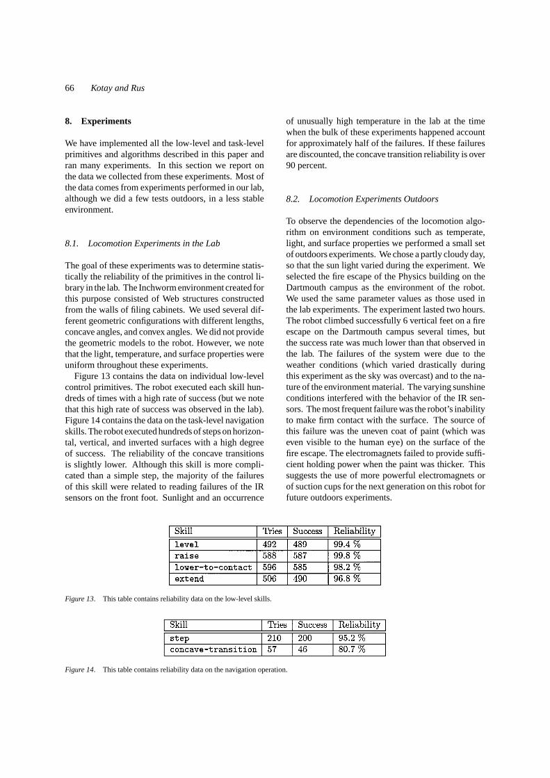
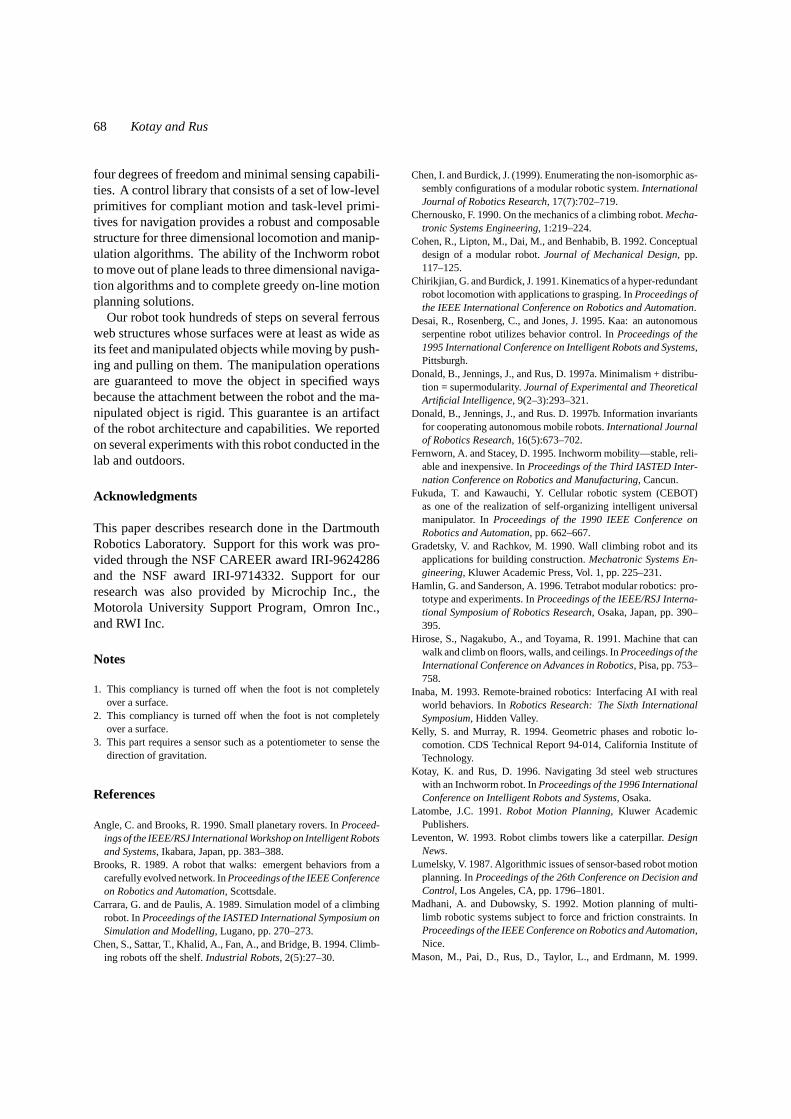
Figure 13 contains the data on individual low-levelcontrol primitives. The robot executed each skill hun-dreds of times with a high rate of success (but we notethat this high rate of success was observed in the lab).Figure 14 contains the data on the task-level navigationskills. The robot executed hundreds of steps on horizon-tal, vertical, and inverted surfaces with a high degreeof success. The reliability of the concave transitionsis slightly lower. Although this skill is more compli-cated than a simple step, the majority of the failuresof this skill were related to reading failures of the IRsensors on the front foot. Sunlight and an occurrence
Figure 13. This table contains reliability data on the low-level skills.
Figure 14. This table contains reliability data on the navigation operation.
of unusually high temperature in the lab at the timewhen the bulk of these experiments happened accountfor approximately half of the failures. If these failuresare discounted, the concave transition reliability is over90 percent.
8.2. Locomotion Experiments Outdoors
To observe the dependencies of the locomotion algo-rithm on environment conditions such as temperate,light, and surface properties we performed a small setof outdoors experiments. We chose a partly cloudy day,so that the sun light varied during the experiment. Weselected the fire escape of the Physics building on theDartmouth campus as the environment of the robot.We used the same parameter values as those used inthe lab experiments. The experiment lasted two hours.The robot climbed successfully 6 vertical feet on a fireescape on the Dartmouth campus several times, butthe success rate was much lower than that observed inthe lab. The failures of the system were due to theweather conditions (which varied drastically duringthis experiment as the sky was overcast) and to the na-ture of the environment material. The varying sunshineconditions interfered with the behavior of the IR sen-sors. The most frequent failure was the robot’s inabilityto make firm contact with the surface. The source ofthis failure was the uneven coat of paint (which waseven visible to the human eye) on the surface of thefire escape. The electromagnets failed to provide suffi-cient holding power when the paint was thicker. Thissuggests the use of more powerful electromagnets orof suction cups for the next generation on this robot forfuture outdoors experiments.

The Inchworm Robot 67
8.3. Manipulation Experiments in the Lab
We also implemented the skills that allow the robotto manipulate objects in a lab setting, using the sameenvironment as in the locomotion experiments.
We implemented the(sweep) algorithm to test the(lift-and-place) skills, and the(pull) algorithmto test the(connect),(stride), and(disconnect)skills. All experiments were conducted on a level steelsurface.
The object used in the(sweep) experiments wasa balsa wood block with a steel plate attached to oneside. The weight of the block is 116 grams. A suc-cessful(lift-and-place)means that the object wasgrasped, lifted, moved forward, and lowered. Each suc-cessful(lift-and-place) also implies that the ob-ject was successfully detected and the Inchworm wascorrectly positioned for the(lift-and-place) op-eration, however object detection and Inchworm posi-tioning are part of the(sweep) algorithm not(lift-and-place). In this experiment, all objects detectedin front of the Inchworm were assumed to be movableobjects. As shown in Fig. 15, in 115 trials(lift-and-place) was successful over 92 percent of the time.
In the straight-line pulling experiment, the Inch-worm uses(connect) to attach itself to a wheeledplatform, pulls the platform using two(stride) oper-ations, detaches from the object using(disconnect),and then performs two(step) motions. The resultsof 35 runs of this experiment are shown in Fig. 15. Asthe data shows, the skills are very reliable. It is worthnoting, however, that the(connect) operation is sen-sitive to the initial positions of the robot and the object.For the above experiment, the initial positions of therobot and the object were set by hand. The reason forthis is that the Inchworm does not have a backwardfacing sensor to detect the position of the object. Weintend to add a sensor to overcome this limitation.
Figure 15 also includes data for the globally-controlled leg algorithm. These tasks were componentsof the straight-line pulling experiment. Each pullingexperiment included two(step) tasks. The globally-
Figure 15. This table contains reliability data for the lifting and placing, straight-line pulling experiments, and navigation as a leg experiments.
controlled leg data consists of data for the(stride)component of the pulling experiment. This was donebecause a(stride) consists of the leg motion whichwould be used for each Inchworm in the multi-leggedwalker.
9. Discussion
In this paper we described a minimalist Inchworm robotand on-line locomotion and manipulation algorithmsfor this robot. Thus, this is an example of a multi-functional robot system, that provides an experimentaltestbed for exploring the connection between locomo-tion and manipulation. Multi-functional robot systemsare interesting because they can change their globalrelation to the world to perform different tasks (for ex-ample, manipulation vs. locomotion). Like its biolog-ical counterpart, the Inchworm robot employs a simpleand robust control system and is capable of sophisti-cated navigation and locomotion tasks in the presenceof unknown and unpredictable environmental factors.The basic control system used for locomotion taskscan be also used for manipulation tasks by pushingand pulling, with minimal changes. This manipulationfunctionality can be distributed and generalized to pro-vide parallel locomotion systems that can travel acrossrough terrain. The individual Inchworm control systemfor manipulation can be reconfigured as a crawling orcreeping robot, when the robot is turned so the feet(‘legs’) contact the ground. Thus the same basic controland design paradigms enable both manipulation and lo-comotion. This is a basic form of multi-functional orreconfigurable robotics, in which, as in biological sys-tems, the same set of physical resources can be usedin a different manner, for different tasks, by employingdifferent control pathways or control algorithms.
The Inchworm robot was designed to imitate themovements of the inchworm caterpillar and to supportthree-dimensional on-line locomotion and manipula-tion algorithms. This functionality was achieved by cre-ating a light, linear structure made of four sections with
68 Kotay and Rus
four degrees of freedom and minimal sensing capabili-ties. A control library that consists of a set of low-levelprimitives for compliant motion and task-level primi-tives for navigation provides a robust and composablestructure for three dimensional locomotion and manip-ulation algorithms. The ability of the Inchworm robotto move out of plane leads to three dimensional naviga-tion algorithms and to complete greedy on-line motionplanning solutions.
Our robot took hundreds of steps on several ferrousweb structures whose surfaces were at least as wide asits feet and manipulated objects while moving by push-ing and pulling on them. The manipulation operationsare guaranteed to move the object in specified waysbecause the attachment between the robot and the ma-nipulated object is rigid. This guarantee is an artifactof the robot architecture and capabilities. We reportedon several experiments with this robot conducted in thelab and outdoors.
Acknowledgments
This paper describes research done in the DartmouthRobotics Laboratory. Support for this work was pro-vided through the NSF CAREER award IRI-9624286and the NSF award IRI-9714332. Support for ourresearch was also provided by Microchip Inc., theMotorola University Support Program, Omron Inc.,and RWI Inc.
Notes
1. This compliancy is turned off when the foot is not completelyover a surface.
2. This compliancy is turned off when the foot is not completelyover a surface.
3. This part requires a sensor such as a potentiometer to sense thedirection of gravitation.
References
Angle, C. and Brooks, R. 1990. Small planetary rovers. InProceed-ings of the IEEE/RSJ International Workshop on Intelligent Robotsand Systems, Ikabara, Japan, pp. 383–388.
Brooks, R. 1989. A robot that walks: emergent behaviors from acarefully evolved network. InProceedings of the IEEE Conferenceon Robotics and Automation, Scottsdale.
Carrara, G. and de Paulis, A. 1989. Simulation model of a climbingrobot. InProceedings of the IASTED International Symposium onSimulation and Modelling, Lugano, pp. 270–273.
Chen, S., Sattar, T., Khalid, A., Fan, A., and Bridge, B. 1994. Climb-ing robots off the shelf.Industrial Robots, 2(5):27–30.
Chen, I. and Burdick, J. (1999). Enumerating the non-isomorphic as-sembly configurations of a modular robotic system.InternationalJournal of Robotics Research, 17(7):702–719.
Chernousko, F. 1990. On the mechanics of a climbing robot.Mecha-tronic Systems Engineering, 1:219–224.
Cohen, R., Lipton, M., Dai, M., and Benhabib, B. 1992. Conceptualdesign of a modular robot.Journal of Mechanical Design, pp.117–125.
Chirikjian, G. and Burdick, J. 1991. Kinematics of a hyper-redundantrobot locomotion with applications to grasping. InProceedings ofthe IEEE International Conference on Robotics and Automation.
Desai, R., Rosenberg, C., and Jones, J. 1995. Kaa: an autonomousserpentine robot utilizes behavior control. InProceedings of the1995 International Conference on Intelligent Robots and Systems,Pittsburgh.
Donald, B., Jennings, J., and Rus, D. 1997a. Minimalism + distribu-tion = supermodularity.Journal of Experimental and TheoreticalArtificial Intelligence, 9(2–3):293–321.
Donald, B., Jennings, J., and Rus. D. 1997b. Information invariantsfor cooperating autonomous mobile robots.International Journalof Robotics Research, 16(5):673–702.
Fernworn, A. and Stacey, D. 1995. Inchworm mobility—stable, reli-able and inexpensive. InProceedings of the Third IASTED Inter-nation Conference on Robotics and Manufacturing, Cancun.
Fukuda, T. and Kawauchi, Y. Cellular robotic system (CEBOT)as one of the realization of self-organizing intelligent universalmanipulator. InProceedings of the 1990 IEEE Conference onRobotics and Automation, pp. 662–667.
Gradetsky, V. and Rachkov, M. 1990. Wall climbing robot and itsapplications for building construction.Mechatronic Systems En-gineering, Kluwer Academic Press, Vol. 1, pp. 225–231.
Hamlin, G. and Sanderson, A. 1996. Tetrabot modular robotics: pro-totype and experiments. InProceedings of the IEEE/RSJ Interna-tional Symposium of Robotics Research, Osaka, Japan, pp. 390–395.
Hirose, S., Nagakubo, A., and Toyama, R. 1991. Machine that canwalk and climb on floors, walls, and ceilings. InProceedings of theInternational Conference on Advances in Robotics, Pisa, pp. 753–758.
Inaba, M. 1993. Remote-brained robotics: Interfacing AI with realworld behaviors. InRobotics Research: The Sixth InternationalSymposium, Hidden Valley.
Kelly, S. and Murray, R. 1994. Geometric phases and robotic lo-comotion. CDS Technical Report 94-014, California Institute ofTechnology.
Kotay, K. and Rus, D. 1996. Navigating 3d steel web structureswith an Inchworm robot. InProceedings of the 1996 InternationalConference on Intelligent Robots and Systems, Osaka.
Latombe, J.C. 1991.Robot Motion Planning, Kluwer AcademicPublishers.
Leventon, W. 1993. Robot climbs towers like a caterpillar.DesignNews.
Lumelsky, V. 1987. Algorithmic issues of sensor-based robot motionplanning. InProceedings of the 26th Conference on Decision andControl, Los Angeles, CA, pp. 1796–1801.
Madhani, A. and Dubowsky, S. 1992. Motion planning of multi-limb robotic systems subject to force and friction constraints. InProceedings of the IEEE Conference on Robotics and Automation,Nice.
Mason, M., Pai, D., Rus, D., Taylor, L., and Erdmann, M. 1999.
The Inchworm Robot 69
A mobile manipulator. InProceedings of the 1999 InternationalConference on Robotics and Automation.
Mason, M., Pai, D., Rus, D., Howell, J., Taylor, L., and Erdmann,M. (to appear). Experiments with desktop mobile manipulators.In Experimental Robotics VI, Corke, P. (Eds.), LNCIS, SpringerVerlag.
Murata, S., Kurokawa, H., and Shigeru Kokaji. 1994. Self-assembling machine. InProceedings of the 1994 IEEE Interna-tional Conference on Robotics and Automation, San Diego.
Nagakubo, A. and Hirose, S. 1994. Walking and running ofthe quadruped wall-climbing robot. InProceedings of theIEEE Conference on Robotics and Automation, San Diego,pp. 1005–1012.
Neubauer, W. 1994. A spider-like robot that climbs vertically in ductsor pipes. InProceedings of the 1994 International Conference onIntelligent Robots and Systems, Munich.
Neville, B. and Sanderson, A. 1996. Tetrabot family tree: modu-lar synthesis of kinematic structures for parallel robotics. InPro-ceedings of the IEEE/RSJ International Symposium of RoboticsResearch, Osaka, Japan, pp. 382–390.
Nilsson, N. 1984. Shakey the robots. Technical Report 323, SRIInternational.
Nishi, A. 1992. A biped walking robot capable of moving on a verticalwall. Mechatronics, 12(6):543–554.
Opler, P. 1994.Peterson First Field Guides–Butterflies and Moths,Houghton Mifflin.
Pamecha, A., Chiang, C.-J., Stein, D., and Chirikjian, G. 1996. De-sign and implementation of metamorphic robots. InProceedingsof the 1996 ASME Design Engineering Technical Conference andComputers in Engineering Conference, Irvine, CA.
Paredis, C. and Khosla, P. 1995. Design of modular fault tolerantmanipulators. InThe First Workshop on the Algorithmic Founda-tions of Robotics, Goldberg, K., Halperin, D., Latombe, J.-C., andWilson, R. (Eds.), pp. 371–383.
Paredis, C. and Khosla, P. 1993. Kinematic design of serial linkmanipulators from task specifications.International Journal ofRobotic Research, 12(3):274–287.
Pai, D., Barman, R., and Ralph, S. 1994. Platonic beasts: a new fam-ily of multilimbed robots. InProceedings of the 1994 InternationalConference on Robotics and Automation, pp. 1019–1025.
Rus, D. and Kotay, K. 1999. Locomotion versatility throughself-reconfiguration.Robotics and Autonomous Systems, 26:217–232.
Xu, Y. and Ueno, H. 1994. Modelling and configuration-independent
control of a self-mobile space manipulator.Journal of Intelligentnd Robotic Systems, (10):37–58.
Xu, Y., Brown, B., Aoki, S., and Kanade, T. 1994. Mobility andmanipulation of a light-weight space robot.Journal of Roboticsand Autonomous Systems, 13:1–12.
Yim, M. 1993. A reconfigurable modular robot with multiple modesof locomotion. InProceedings of the 1993 JSME Conference onAdvanced Mechatronics, Tokyo, Japan.
Keith Kotay is a Ph.D. candidate in the Computer Science Depart-ment at Dartmouth College. He holds a Masters Degree in Com-puter Science from Dartmouth College, and B.S. and B.A. Degreesfrom Lebanon Valley College. His research interests include self-reconfiguring robotic systems, 3-D navigation and manipulation, andmobile robots.
Daniela Rusis an assistant professor in the Computer Science De-partment at Dartmouth, where she founded and directs the DartmouthRobotics Laboratory. She also co-founded and co-directs the Trans-portable agents Laboratory and the Dartmouth Center for MobileComputing. She holds a Ph.D. degree in computer science formCornell University. Her research interests include distributed ma-nipulation, 3d navigation, self-reconfiguring robotics, mobile agents,and information organization. She is a Alfred P. Sloan FoundationFellow and holds an NSF Career award.