
The Implementation of a Special Language Interpreter for ...
104
W&M ScholarWorks W&M ScholarWorks Dissertations, Theses, and Masters Projects Theses, Dissertations, & Master Projects 1974 The Implementation of a Special Language Interpreter for the The Implementation of a Special Language Interpreter for the Control Data 3100 Computer Control Data 3100 Computer James Thomas Lee College of William & Mary - Arts & Sciences Follow this and additional works at: https://scholarworks.wm.edu/etd Part of the Computer Sciences Commons Recommended Citation Recommended Citation Lee, James Thomas, "The Implementation of a Special Language Interpreter for the Control Data 3100 Computer" (1974). Dissertations, Theses, and Masters Projects. Paper 1539624886. https://dx.doi.org/doi:10.21220/s2-1czt-td53 This Thesis is brought to you for free and open access by the Theses, Dissertations, & Master Projects at W&M ScholarWorks. It has been accepted for inclusion in Dissertations, Theses, and Masters Projects by an authorized administrator of W&M ScholarWorks. For more information, please contact [email protected].
Transcript of The Implementation of a Special Language Interpreter for ...

W&M ScholarWorks W&M ScholarWorks
Dissertations, Theses, and Masters Projects Theses, Dissertations, & Master Projects
1974
The Implementation of a Special Language Interpreter for the The Implementation of a Special Language Interpreter for the
Control Data 3100 Computer Control Data 3100 Computer
James Thomas Lee College of William & Mary - Arts & Sciences
Follow this and additional works at: https://scholarworks.wm.edu/etd
Part of the Computer Sciences Commons
Recommended Citation Recommended Citation Lee, James Thomas, "The Implementation of a Special Language Interpreter for the Control Data 3100 Computer" (1974). Dissertations, Theses, and Masters Projects. Paper 1539624886. https://dx.doi.org/doi:10.21220/s2-1czt-td53
This Thesis is brought to you for free and open access by the Theses, Dissertations, & Master Projects at W&M ScholarWorks. It has been accepted for inclusion in Dissertations, Theses, and Masters Projects by an authorized administrator of W&M ScholarWorks. For more information, please contact [email protected].

THE IMPLEMENTATION OF A SPECIAL LANGUAGE INTERPRETER FOR THE CONTROL DATA 3100 COMPUTER.
A Thesis Presented to
The Faculty of the Department of Applied Science
The College of William and Mary in Virginia
In Partial Fulfillment
Of the Requirements' for the Degree of
Master of Science
by
James Thomas Lee, Jr.
APPROVAL SHEET
This thesis is submitted in partial fulfillment of
the requirements for the degree of
Master of Science
James Thomas Le' J i.
Approved, August 1975
Michael K. Donegan
Norman E. Gibbs

TABLE OF CONTENTSPage
LIST OF FIGURES..................... iv
ABSTRACT................................................. v
SECTIONI. THE CDC 3100 COMPUTER SYSTEM . . . . . . . . . . . . 1
Hardware Configuration. . ............... . . . . 1The ECDAPS Software System............... 3An Changing Program In An Everchanging System . . 5
II. THE INTERPRETER IN DESIGN.................. 10The First Pass............. 10The Second Pass ................... 26
Executable instructions............. *29Instructions which affect the program
execution................................... 29Input/Output Request Instructions . . . 36
Expressions............................ 51Normal Expressions............ 51Logical Expressions,. . . . . . . . . . 62
III. THE DATA DUMP................................. 65
IV. THE DIAGNOSTIC SYSTEM............................ 73
V. CLOSING COMMENTS........... 84
APPENDIX A. THE MAT STATEMENT IN U S E .............* 88
APPENDIX B. FUNCTION ACCURACY. . . .............. - 91
APPENDIX C. LOGICAL EXPRESSIONS..................... . 94
BIBLIOGRAPHY................. - ......... . 96
iii
LIST OF FIGURESFigure Page
1. The CDC 3100 Computer System Hardware Configuration. . 2
•2. The First Pass of the Interpreter. . . . . . . . . . 12
3. Example of Interpreter's input conversion routines . 24
4. The Development of the First Pass Tables........... 27
5. The Instruction Set capability for the Second Pass . . 30
6. Example of Interpreter's output conversion routines.. . 39
7. Sample Data Dump . . . . . ........... . 668. Sample of Diagnostic Messages. . . . . . . . . . . • 74
9. Examples of MAT Statement. . . . . . . . . . . . . . 89
10. Examples of WRITE Statement without MAT Statement. . 90
• 11. Function Preciseness, (I) . . . . . . . . . . . . . . 92
12. Function Preciseness, (II). 93
13. Boolean Expressions . . . . . . . . . . . . . . . - 95
iv
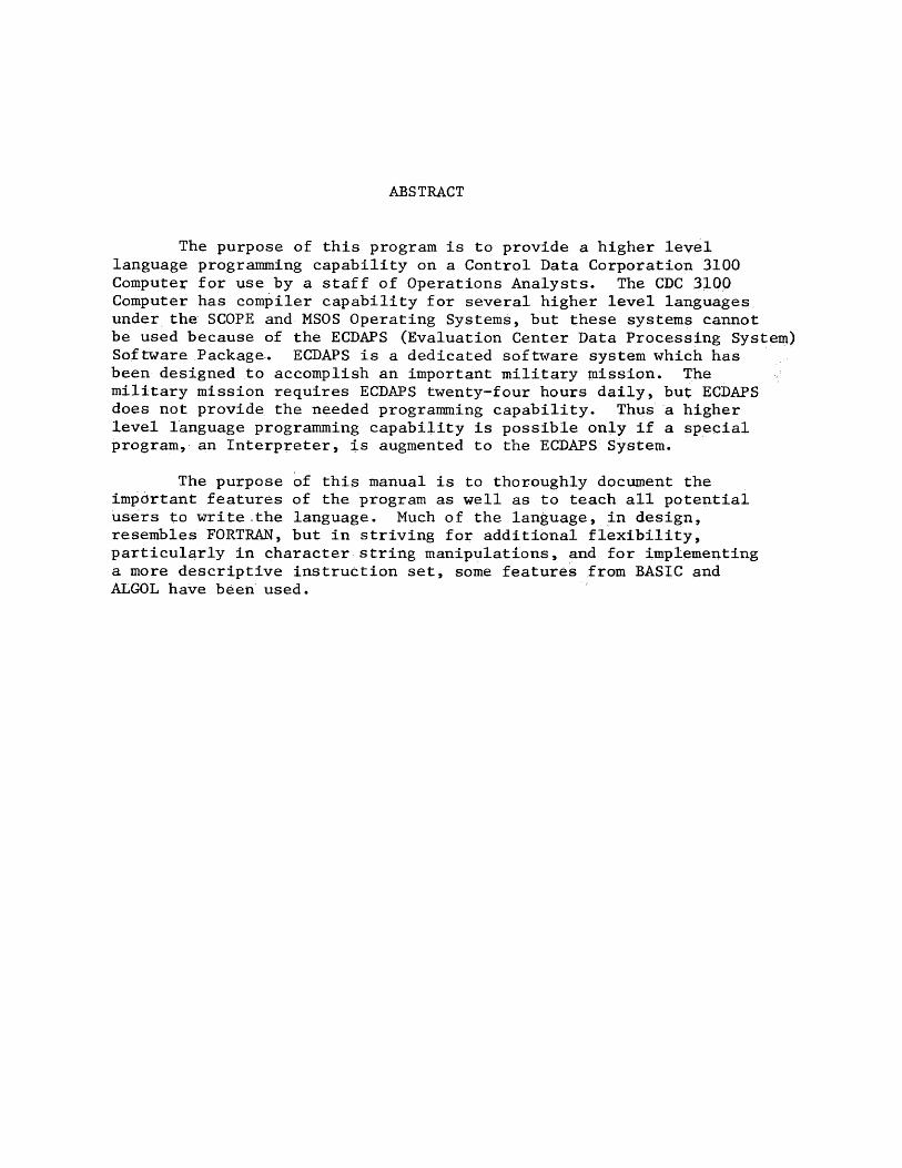
ABSTRACT
The purpose of this program is to provide a higher level language programming capability on a Control Data Corporation 3100 Computer for use by a staff of Operations Analysts. The CDC 3100 Computer has compiler capability for several higher level languages under the SCOPE and MSOS Operating Systems, but these systems cannot be used because of the ECDAPS (Evaluation Center Data Processing System) Software Package. ECDAPS is a dedicated software system which has been designed to accomplish an important military mission. The military mission requires ECDAPS twenty-four hours daily, but ECDAPS does not provide the needed programming capability. Thus a higher level language programming capability is possible only if a special program, an Interpreter, is augmented to the ECDAPS System,
The purpose of this manual is to thoroughly document the important features of the program as well as to teach all potential users to write the language. Much of the language, in design, resembles FORTRAN, but in striving for additional flexibility, particularly in character string manipulations, and for implementing a more descriptive instruction set, some features from BASIC and ALGOL have been used.
THE IMPLEMENTATION OF A SPECIAL LANGUAGE
INTERPRETER FOR THE CONTROL DATA 3100 COMPUTER
I. THE CDC 3100 COMPUTER SYSTEM
A. Hardware Configuration
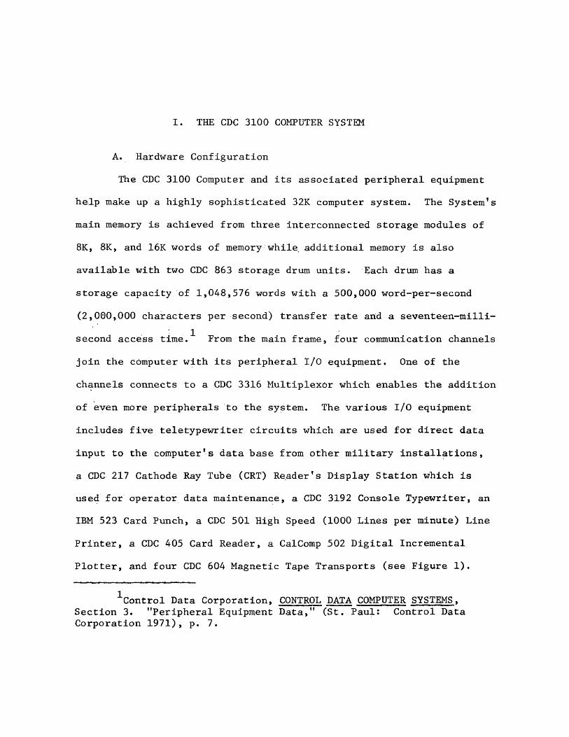
The CDC 3100 Computer and its associated peripheral equipment
help make up a highly sophisticated 32K computer system. The System's
main memory is achieved from three interconnected storage modules of
8K, 8K, and 16K words of memory while additional memory is also
available with two CDC 863 storage drum units. Each drum has a
storage capacity of 1,048,576 words with a 500,000 word-per-second
(2,000,000 characters per second) transfer rate and a seventeen-milli
second access time.^ Prom the main frame, four communication channels
join the computer with its peripheral I/O equipment. One of the
channels connects to a CDC 3316 Multiplexor which enables the addition
of even more peripherals to the system. The various I/O equipment
includes five teletypewriter circuits which are used for direct data
input to the computer's data base from other military installations, a CDC 217 Cathode Ray Tube (CRT) Reader's Display Station which is used for operator data maintenance, a CDC 3192 Console Typewriter, an IBM 523 Card Punch, a CDC 501 High Speed (1000 Lines per minute) Line
Printer, a CDC 405 Card Reader, a CalComp 502 Digital Incremental
Plotter, and four CDC 604 Magnetic Tape Transports (see Figure 1).
■^Control Data Corporation, CONTROL DATA COMPUTER SYSTEMS, Section 3. "Peripheral Equipment Data," (St. Paul: Control DataCorporation 1971), p. 7.

pciwCM HCTv W Mi—1PCO OCO Wo a P*P OCJ CJ H
EHM[3oPiEh M
H CJ
wo<5 piW Wo O clCO H hivO CO oCO pi§ HCJ S S25P Pi oCJ Q CJ
CMOCMW55 Eho Wtt COPMw <3hi Rw <3H P
HB
>H P̂ EH W H CJ
CO vD 00 a « hO £3 O H U R W P
co W\DooS 3 HCJ pj O HP Pi EH S;u p CO 2
PiwHPP &O orH CJOO 1PHP 55W WCO S CO
HPH33CJPiH 1—1H CJ
PiHPiw
hihiQH PiH f-Hohi oPm CJ
Pi PiWMoo 2 hifxj hirvl Pi roCO Pi§HCJ 52?P <3 oCJ CJ CJ
PiwvO Pi him RCM N oCO H PiCJ HO jgp h-1 oCJ Ph o
in S 3r*§ PCM qCO PiQ EHCJ 2 55P OCJ'u O
wS!
v O H . C OHU CJ PiCM O MOH PM O H CO pi W COO O
CM hiO <3inP*H w PiB <2 s Wo H pu Ho M pi EH1—1CD CJ OcO M 55 hiCJ P M Pm
Piwpino
<1sHf
CJQO CJ
piWH55H1— 1 Pio PMm wCJ 55P HCJ hi
P3CJCO H<N PMmS §PQ <H CJ Fi
gure
1. The
CDC
310
0 Computer
System
Hardward
Configuration.

In addition to the I/O equipment mentioned above, a mini
computer system interfaces, through the Multiplexor, with the CDC 3100
Computer System. The second system, consisting of a Sander’s Computer
Interactive Display (CID), a Scientific Engineering Laboratory (SEL)
810B mini-computer (16K), an ADDS 900 Digital Converter, and a Bell
Telephone Laboratories 202 Data Set, enables a user-controlled display
of data that is in the computer. A program request initiated from the
CID Station causes a program execution at the CDC 3100 Computer with
the subsequent data output transferred to the SEL 810B computer.
From the SEL 810B system, the data is forwarded by the ADDS 900 to
the Sander CID for display. Since data are displayed simultaneously by this system in both an alphanumeric and a geographic mode, a CID
system is a key part of the Overall CDC 3100 system, but the second
system is always subordinate to and dependent upon the CDC 3100 system,
and should be thought of as another I/O device.
B. The ECDAPS Software System
The hardware described above becomes a complete system with the
addition of ECDAPS. As stated earlier, ECDAPS is a dedicated software
system which operates twenty-four hours daily on the CDC 3100 Computer.
The software package was initially developed by, and is still maintained
by the Bell Telephone Laboratories, Greensboro, North Carolina. The
first ECDAPS, in 1968, was packed into only 16K words of core; hence,
the main frame is composed of interconnected storage modules (as
opposed to one larger unit) and other special-function optional modules
which mark the gradual growth of the system. As the system has grown,
new hardware has been added to the old, and new software has been added

to ECDAPS. In recent years, ECDAPS has seen major hardware additions,
such as the two CDC 863 storage drum units and the CID System. With
these additions and continuing research developments, ECDAPS has
changed and is still changing.
Through all the additions, ECDAPS has developed into a massive
system of programs, most of which operate on a single data base or
other data bases which are derived from the one data base. Among the
different types of programs in the system are routines which list the
data (in different formats), routines which calculate statistics or
perform other meaningful analysis, routines which handle data maintenance,
and routines which drive the CID System. The large volume of programs
requires special storage consideration to eliminate the many possible
conflicts which might occur with swapping programs in and out of core.
For this reason, the first drum is divided into regions of 12K words
each for program storage. When a program request is made, the computer
loads the entire 12K region into core. Filling but the main memory is
a section of program called Utility. Utility contains the data con
version routines, the mathematical functions, and other miscellaneous
often-required routines which are essential for program execution.
The region loaded is then able to link with the Utility routines
and perform the requested program execution. When execution is
complete,-the 12R region is returned to its place on the drum.
Although desirable, the ECDAPS does not have multiprogramming or an adequate priority interrupt system. As a result, many times the system will require users to wait for the completion of current
program requests even though the waiter may have a higher priority
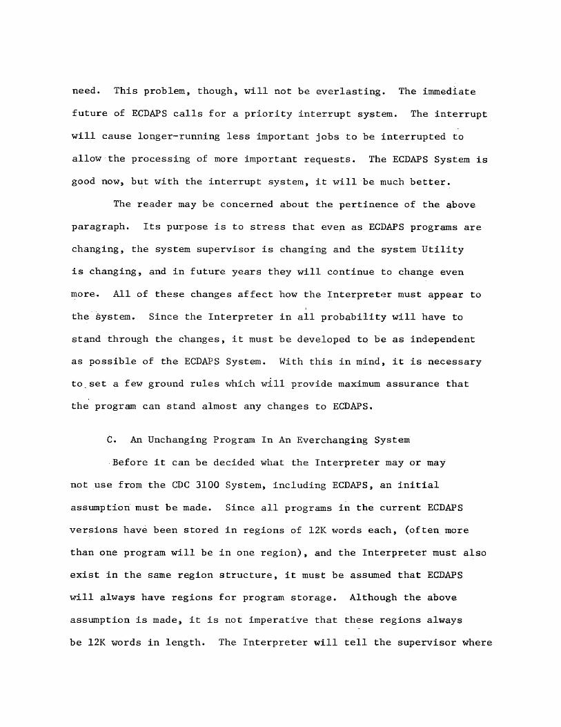
need. This problem, though, will not be everlasting. The immediate
future of ECDAPS calls for a priority interrupt system. The interrupt
will cause longer-running less important jobs to be interrupted to
allow the processing of more important requests. The ECDAPS System is
good now, but with the interrupt system, it will be much better.
The reader may be concerned about the pertinence of the above
paragraph. Its purpose is to stress that even as ECDAPS programs are
changing, the system supervisor is changing and the system Utility
is changing, and in future years they will continue to change even
more. All of these changes affect how the Interpreter must appear to
the system. Since the Interpreter in all probability will have to
stand through the changes, it must be developed to be as independent as possible of the ECDAPS System. With this in mind, it is necessary
to set a few ground rules which will provide maximum assurance that
the program can stand almost any changes to ECDAPS.
C. An Unchanging Program In An Everchanging System
Before it can be decided what the Interpreter may or may
not use from the CDC 3100 System, including ECDAPS, an initial
assumption must be made. Since all programs in the current ECDAPS
versions have been stored in regions of 12K words each, (often more
than one program will be in one region), and the interpreter must also
exist in the same region structure, it must be assumed that ECDAPS
will always have regions for program storage. Although the above
assumption is made, it is not imperative that these regions always
be 12K words in length. The Interpreter will tell the supervisor where

6
it lives by a region number, and the supervisor will then take over.
So with this assumption, the concern can rightfully turn to which
routines, or more accurately, which type of routines are to be included
or excluded. Logically those routines which are still in a develop
mental mode and are likely to change must be excluded. Such routines
are the ones which support the CID System. The CID System is still very
new, and is constantly changing. Of consideration would be to duplicate
some vital CID functional routines as part of the Interpreter, but the
amount of core required makes such thinking impractical. So whereas
the CID System might have been beneficial to users with access to the
higher level language capability provided by the Interpreter, its
software must be regarded as continually changing software to be avoided.
Also likely to change over time are routines which pass arguments.
The arguments passed by these routines are often subject to change
as new system capabilities or needs are created; therefore, routines
which pass arguments and also routines which may in the future be
required to pass arguments should be removed from the Interpreter.
Essentially after a review of ECDAPS, it becomes apparent that most
routines cannot be used for one of the two above reasons. Therefore,
rather than try any longer to second guess the future of ECDAPS, the
Interpreter will rely only on the system routines which have not
changed, and which logically should never change. These routines are
mostly of the variety which make I/O requests of the peripheral equipment and those routines which access the computer's data base.
It should be noted that even these routines are not absolutely
guaranteed never to change, but they should not change significantly
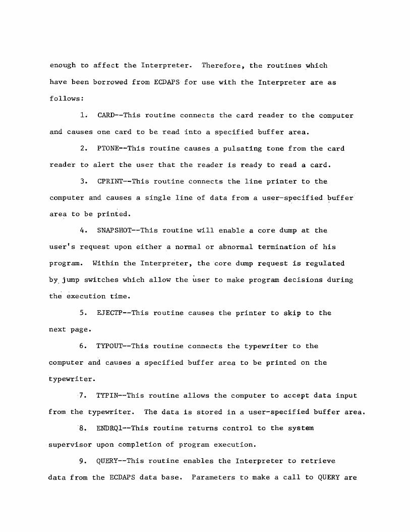
enough to affect the Interpreter. Therefore, the routines which
have been borrowed from ECDAPS for use with the Interpreter are as
follows:
1. CARD-— This routine connects the card reader to the computer
and causes one card to be read into a specified buffer area.
2. PTONE— This routine causes a pulsating tone from the card
reader to alert the user that the reader is ready to read a card.
3. CPRINT— This routine connects the line printer to the
computer and causes a single line of data from a user-specified buffer area to be printed.
4. SNAPSHOT— This routine will enable a core dump at the
user’s request upon either a normal or abnormal termination of his
program. Within the Interpreter, the core dump request is regulated
by jump switches which allow the user to make program decisions during
the execution time.
5. EJECTP— This routine causes the printer to skip to the
next page.
6. TYPOUT— -This routine connects the typewriter to the
computer and causes a specified buffer area to be printed on the
typewriter.
7. TYPIN— -This routine allows the computer to accept data input
from the typewriter. The data is stored in a user-specified buffer area.8. ENDRQ1— This routine returns control to the system
supervisor upon completion of program execution.
9. QUERY— This routine enables the Interpreter to retrieve
data from the ECDAPS data base. Parameters to make a call to QUERY are

8
defined by the user with the Interpreter's FILE Statement (see Section
IIB, para. Ib5). Once the data has been retrieved from storage,
QUERY places it in a special area and makes it available to the
Interpreter by a pointer called ENTRY. ENTRY is a location in core
which contains the absolute address of the data buffer. With that
information, the Interpreter can fulfill user-oriented requests on the
data.
10. DATA— QUERY is only responsible for initially retrieving a
block of data which matches the specified parameters. Once the data is retrieved and stored in core, QUERY is finished. DATA then becomes
necessary for repeated calls to the already stored special buffer.
Essentially, DATA serves to update the pointer ENTRY.
11. ENTRY^— As the reader probably has noted, ENTRY is the
magic key which leads the Interpreter to the location of the data
retrieved and stored by QUERY.
12. T777— When the end of file was found by QUERY, it made a
notation, T777, which could alert the Interpreter that the end of file
was encountered. As a result, the Interpreter carries the tradition
to the user by conveniently providing a technique whereby the
Interpreter will continue to load data from the data base until the end of file is found (see Section IIB, para. 15b).
13. GCLFLT4— This is the system's location for the computer clock.
The Interpreter uses the computer clock to avoid an infinite loop in the nonconvergent case of the WHILE Statement (see Section IIB, para.
Ia6).

9
14. PHOLL— This routine causes an eighty-character, user-
specified buffer area to be punched in Hollerith code on the card punch.
With such a small selection of system routines used by the
Interpreter, many subroutines are required to fill the gaps. The
user program, when read into the computer, is in binary coded decimal
(BCD) format and must be converted to binary. Conversely, when the
results of the program are ready to be printed, the data must be
converted back to BCD from binary. Conversion routines will be
necessary to convert real numbers, or floating point numbers, to the floating point notation for input and subsequent calculations, and from
floating point notation back to a BCD real number for output. In
addition, all mathematical routines must be developed and coded. Thus,
a major effort in the development of the Interpreter will be the
creation of a library of programs’ or utility routines to satisfy the
programming requirements of the user. In the following pages, these
routines will be discussed more carefully as seems appropriate.

II. THE INTERPRETER IN DESIGN
A. The First Pass
Although the Interpreter involves execution of each instruction
as read, some instructions may require branching to another part of
the program, or it may involve the execution of a programmed logical
loop. If these types of programming options are to be available to the
user, then the Interpreter must have certain vital information about
the user’s program for ready reference. Such information might include
the address of a statement which is to be branched to or the location
of pertinent input data. To make ready this information for the
Interpreter, a two-pass technique is employed. The Interpreter, in
the first pass, will read and store the user's source program, will
set up tables of names and address pointers, and will maintain
significant counters. As a result, when a branch to another part of
the program is requested, the address of the next instruction will
be readily available without requiring a clumsy and time-consuming
program search. In addition, when a variable is used, its location,
data type, and current value will be on hand and easily accessible.
Paying Close attention to the construction of the tables in the first
pass will result in a smoother flowing execution phase in the second
pass.
Tables to be maintained and developed in the first pass are a
source text listing table, a variable reference table, a table of
10
11
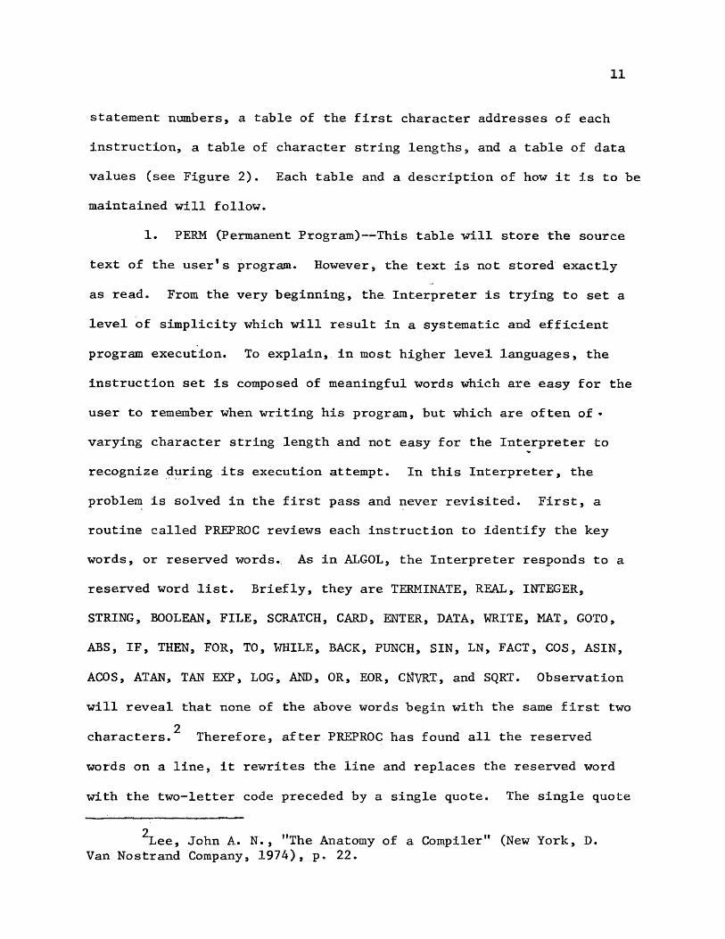
statement numbers, a table of the first character addresses of each
instruction, a table of character string lengths, and a table of data
values (see Figure 2). Each table and a description of how it is to be
maintained will follow.
1. PERM (Permanent Program)— This table will store the source
text of the user’s program. However, the text is not stored exactly
as read. From the very beginning, the Interpreter is trying to set a
level of simplicity which will result in a systematic and efficient
program execution. To explain, in most higher level languages, the
instruction set is composed of meaningful words which are easy for the
user to remember when writing his program, but which are often of *
varying character string length and not easy for the Interpreter to
recognize during its execution attempt. In this Interpreter, the
problem is solved in the first pass and never revisited. First, a
routine called PREPROC reviews each instruction to identify the key
words, or reserved words. As in ALGOL, the Interpreter responds to a
reserved word list. Briefly, they are TERMINATE, REAL* INTEGER,
STRING, BOOLEAN, FILE, SCRATCH, CARD, ENTER, DATA, WRITE, MAT, GOTO,
ABS, IF, THEN, FOR, TO, WHILE, BACK, PUNCH, SIN, LN, FACT, COS, ASIN,
ACOS, AT AN, TAN EXP, LOG, AND, OR, EOR, CNVRT, and SQRT. Observation
will reveal that none of the above words begin with the same first two 2characters. Therefore, after PREPROC has found all the reserved
words on a line, it rewrites the line and replaces the reserved word
with the two-letter code preceded by a single quote. The single quote
2Lee, John A. N. , "The Anatomy of a Compiler" (New York, D.Van Nostrand Company, 1974), p. 22.

12
START
CARD c o n t a i n: IS READ AND
[NG INSTRUCTION STORED IN INST
MODIFIED TEXT STORED IN PERM
CHECK FOR STATEMENT NUMBER. IF FOUND, MAKE TABLES ENTRY
CHECK STATEM]5NT TYPE
DATASTATEMENT
EVALUATE AND CONVERT ENTRY TO PROPER. DATA TYPE AND STORE IN DATATAB
OTHER
IF MORE CARDS, GO TO START, OTHERWISE, CONTINUE BELOW.
CHECK FOR DATA DUMP OPTION. IF REQUESTED, DUMP THE TABLES DEVELOPED IN THE FIRST PASS.
CHECK LAST CARD FOR TERMI- NATE. IF NOT FOUND, ABORT.
SET UP PI AND STAR AS DECLARED VARIABLES.
CONTINUE TO THE SECOND PASS
DECLARATIONSTATEMENT
FOR DECLARED VARIABLES. MAKE TABLES ENTRY.
IF STRING, MAKE CHARACTER LENGTH ENTRY IN STLGTAB
Figure 2. The First Pass of the Interpreter.

13
is included to alert the Interpreter that a reserved word follows and
not just a two-digit variable name. Of note, the single quote should
never appear to the Interpreter at any other time except in a
character string; however any character string will be enclosed between
double quotes and protected from a possible misinterpretation by the
Interpreter. In addition to establishing a simple instruction
recognition procedure, the above method of program storage can help
reduce the amount of core required for program storage. Final prepara
tion for storage is to add a semicolon to end the instruction. This
actually has a two-fold purpose. First, the user can extend his
statement from one card to another without concern. In many higher
level languages, like FORTRAN, the user must put a special character
in a particular column on his card to have multi-card instructions,
and this can be bothersome. Secondly, the semicolon assists the
Interpreter in locating the end of an instruction. Of course, the
Interpreter can continue to read the user1s program until the next
instruction is found or until the Interpreter thinks it has found the
next instruction, but this would require more extensive and really
unnecessary programming. Also, as in the case with the single quote,
the semicolon should not in any way cause horrendous problems for the
Interpreter by way of misinterpretation. Now that the instruction has
been prepared for storage, a few examples follow of the instruction
as the Interpreter sees it:
INPUT IN STORAGE
REAL X, Y, Z fREX, Y, Z;
A=(B+TAN(X))+75 A=(B+1TA(X))+75;
TERMINATE fTE;

14
As stated above, the problem of instruction recognition is
resolved in the first pass. This is possible through a special routine,
DETEMN (Determine Instruction Type), which has been developed as a
follow-up to the above program preparation. Thus, whenever a single
quote is found, the next two characters are read, and a call is made
to DETRMN. When the instruction type has been determined, the routine
returns the first word address of the routine which will execute the
instruction.2. TABLES— When the Interpreter has knowledge of the statement
type being used, the next problem to be encountered is the variable
name'. When the Interpreter reads a variable name in the user’s
program, a number of questions are asked. First of all, was the
variable properly declared by a Declaration Statement (Declaration
Statements will be discussed below)? If not, then the Interpreter
does not recognize it, and no analysis or calculation can take place.
A second question asked by the Interpreter is, What is the variable’s
data type? This is important because if the type is string variable,
then the Interpreter is dealing with variable length constants. If
the type is real number, then the Interpreter must be ready to deal
with floating point notation; that is, to make floating point
conversions and calculations. If the data type is boolean, then the Interpreter must use a special routine for boolean expressions (BOOLSTOR).
Only if the type is integer does the Interpreter do nothing special to prepare. Another question to be answered is, Are arrays being
used? If they are, the Interpreter is then tasked with determining the
displacement between the first word of the array in storage and the

15
desired element of the array. When you consider the variable word
lengths used by character strings and real numbers, then you can begin
to imagine the difficulty that the Interpreter must face. A final
problem or question, as if the Interpreter needs any mqre, is, Where
can the data variable’s current value be found in storage? To provide
the Interpreter with the answers to these questions is a table called TABLES; however, before any entries can be made, the Interpreter must
find one of the following Declaration Statements:(a) REAL X, Y, Z,...
This instruction enables the user to specify a variable whose
value will be a real number; that is, it will contain a decimal point.
In addition, large numbers using scientific notation are to be expressed
and declared as real numbers.
(b) INTEGER X, Y, Z,...
This instruction enables the user to specify a variable whose
value is an integer; that is, it does not contain a decimal point.
As a word of precaution though, the Interpreter only reserves one
word of core for an integer, so the maximum value allowed in storage
is 77777777 (octal) or 16777215 (decimal). However this value is
further reduced by the WRITE routine which uses the left-most BCD
character as a sign bit. Therefore, the restriction imposed upon an
integer X is that it must be in the range -9999999 (decimal)
_< X _< 9999999 (decimal) . Any integer not within the above range must
be declared as a real number.
16
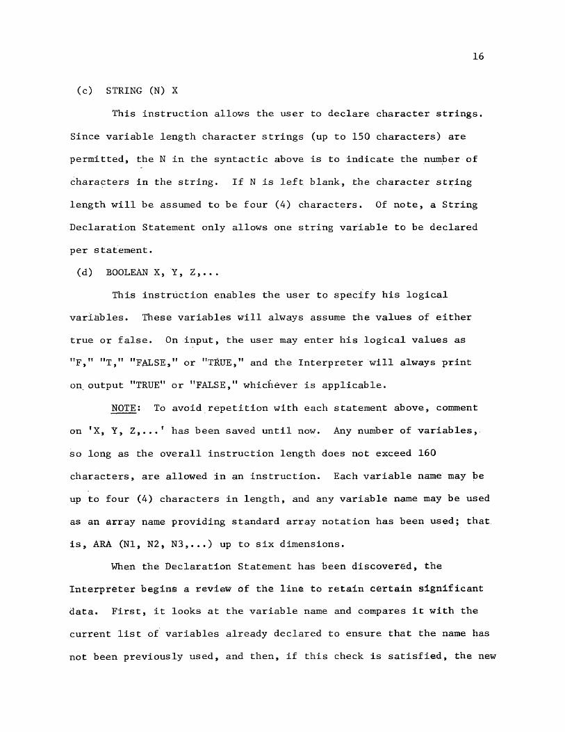
(c) STRING (N) X
This instruction allows the user to declare character strings.
Since variable length character strings (up to 150 characters) are
permitted, the N in the syntactic above is to indicate the number of
characters in the string. If N is left blank, the character string
length will be assumed to be four (4) characters. Of note, a String
Declaration Statement only allows one string variable to be declared
per statement.(d) BOOLEAN X, Y, Z,...
This instruction enables the user to specify his logical
variables. These variables will always assume the values of either
true or false. On input, the user may enter his logical values as
"F," "T," "FALSE," or "TRUE," and the Interpreter will always print
on output "TRUE" or "FALSE," whichever is applicable.
NOTE: To avoid repetition with each statement above, comment
on fX, Y, Z,..if has been saved until now. Any number of variables,
so long as the overall instruction length does not exceed 160
characters, are allowed in an instruction. Each variable name may be
up to four (4) characters in length, and any variable name may be used
as an array name providing standard array notation has been used; that
is, ARA (Nl, N2, N3,...) up to six dimensions.When the Declaration Statement has been discovered, the
Interpreter begins a review of the line to retain certain significant data. First, it looks at the variable name and compares it with the
current list of variables already declared to ensure that the name has
not been previously used, and then, if this check is satisfied, the new

17
name is stored in TABLES. Next, since the data type can be taken
directly from the instruction type, the Interpreter stores the type in
TABLES. This information is stored in a two-digit notation (IN'— Integer,
RE— Real, ST— String, BO-— Boolean). If an array is being declared,
the Interpreter stores the relative character address of the array's
dimensioning specifications in PERM for later use by a routine which
will locate the absolute storage location of a given array element
(ARRAYLOC— Array Element Locator). This relative character address
is stored along with the data type because it can be stored in the
other two character positions of the variable's value in the data
tables. A pointer to the data tables is kept, and as new variables and
arrays are declared, the pointer increments through the data table
to the next available storage location. Before the pointer is
incremented, though, its value is- stored in TABLES as the storage
location of the variables declared. The actual format of entries
into TABLES is as follows:XXXX PPTT AAAA
where XXXX is the variable name, PP is a pointer to the user's program
in PERM if the entry is an array declaration, TT is the two-digit
indicator, and AAAA is the relative displacement of the variable's
storage location from the first word of the data tables.If the variable is a string variable, then the Interpreter
must store some additional data. As stated earlier, a string character may be up to 150 characters in length which requires special
preparation for storage. So that the Interpreter will not become
confused with varying strings lengths, a special table, STLGTAB
18
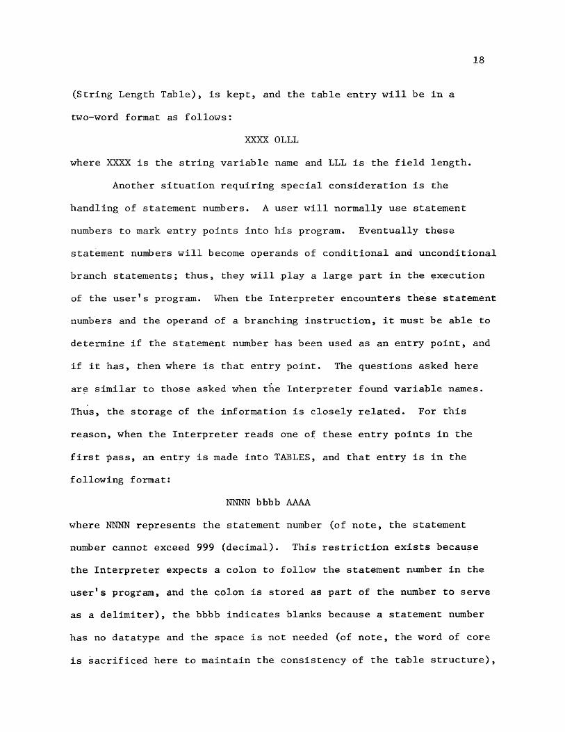
(String Length Table), is kept, and the table entry will be in a
two-word format as follows:
XXXX OLLL
where XXXX is the string variable name and LLL is the field length.
Another situation requiring special consideration is the
handling of statement numbers. A user will normally use statement
numbers to mark entry points into his program. Eventually these
statement numbers will become operands of conditional and unconditional
branch statements; thus, they will play a large part in the execution
of the user’s program. When the Interpreter encounters these statement numbers and the operand of a branching instruction, it must be able to
determine if the statement number has been used as an entry point, and
if it has, then where is that entry point. The questions asked here
are similar to those asked when the interpreter found variable names.
Thus, the storage of the information is closely related. For this
reason, when the Interpreter reads one of these entry points in the
first pass, an entry is made into TABLES, and that entry is in the
following format:
NISTNN bbbb AAAA
where NNNN represents the statement number (of note, the statement number Cannot exceed 999 (decimal). This restriction exists because
the Interpreter expects a colon to follow the statement number in the
user's program, and the colon is stored as part of the number to serve as a delimiter), the bbbb indicates blanks because a statement number
has no datatype and the space is not needed (of note, the word of core
is sacrificed here to maintain the consistency of the table structure),

19
and the AAAA is the relative address of the statement number in the
user's program as stored in PERM.
In discussions of variables and statement numbers, concern has
been expressed about knowing that the variable or statement number
had not been previously declared. The error is obvious; if a
variable or statement number has been declared two or more times, the
Interpreter will not know which storage location to store a value, or
it may not know which entry point to go to on a branching operation.
To check each Declaration Statement for duplicate variables and each
statement number for repetition is a special routine called TABSCAN
(Table Scan). If the routine finds the error, a message is sent to
the user (see Section IV, para 23). Although TABSCAN is instrumental
in determining duplicate variables and repeated statement numbers, it
is also useful to retrieve the specific information which was retained
on the variables and statement numbers. The routine makes a TABLES
search to locate the name or number and return with the stored
information of that name or number.
In the discussion above, note was made of the different problems
which the interpreter must face and resolve for successful processing of variable names and statement numbers. With the specially constructed
TABLES and the routine TABSCAN, the task of the Interpreter in this
area is no longer so difficult.3. STMTTAB (Statement Table)— This table contains the relative
address as stored in PERM of each instruction of the user's program,
except the first, which the Interpreter already knows to be zero. This

20
table is significant during the execution cycle, because it directs
the Interpreter through each instruction of the program.
4. DATATAB (Data Tables)— This table holds the current value
for each data variable which is declared in the user’s program. Entries are made either through a DATA Statement, which is processed in the
first pass, or by an Assignment Statement, which is processed in thesecond pass and will be discussed as part of the second pass
discussion (see Section IIB, para 2). The DATA Statement is of the
form:
DATA NAME, VALUE, NAME, VALUE,...
where NAME is the variable name and it can be an array, and VALUE is
the value assigned to the variable (for character strings, including
Boolean values, VALUE must be enclosed in double quotes).
When the Interpreter finds a DATA Statement, the first task
is to determine the variable used, if it exists, and if it does, then
where does it live? All these questions can be answered using TABSCAN.
Use of TABSCAN will return the data type and the storage location of
the variable, but if the routine is unable to find the variable, then
an error is printed (see Section IV, para 5).Once the Interpreter knows the type of data that it is working
with, it can make the necessary conversions to get the data stored.
Since the storage area has already been assigned by the Interpreter,
according to data type, the Interpreter is concerned only with the
proper conversion and storage, which is no problem; thus, with the
data type returned by TABSCAN, the Interpreter chooses one of the
following conversion techniques:

21
(a) Boolean Variables— Boolean variables take on values of either
TRUE or FALSE. These values are entered into the computer in BCD
format, and stored in BCD format, so no conversion is necessary.
They are stored as read.
(b) String Character Variables— Integers are read into the computer
in BCD format, but since the computer performs calculations in
binary arithmetic, it will be necessary to convert the integer BCD
value to an octal (binary) number. The Interpreter has two routines
which perform the desired conversion. The first, BCDOCT, is designed
to handle small integers known to be fewer than four digit. This
routine is simple and efficient for quick conversions. For data input,
though, it is not known whether the value will be large or small, so
the Interpreter assumes that it will be larger than four digits. For
the large BCD-to-octal conversions, the routine BCDOCTL will convert
numbers up to 12 digits in length. The limitation on BCDOCTL might warn
the user that if he expects an integer larger than 12 digits, he should
declare it a real number and use scientific notation for input to avoid an error.
BCDOCTL converts large and small BCD numbers to octal in
three successive calls to BCDOCT. Initially, the BCD integer is
stored in a three-word storage area, NUMA, left justified and zero
filled to the end of the storage area, and a counter is kept for the
number of BCD digits in the number (call it n). On the first call to
BCDOCT, the first four characters of NUMA from the left are converted
to octal, multiplied by 100,000,000 and stored in a temporary storage
area. On the next call, the second four characters are converted by
22
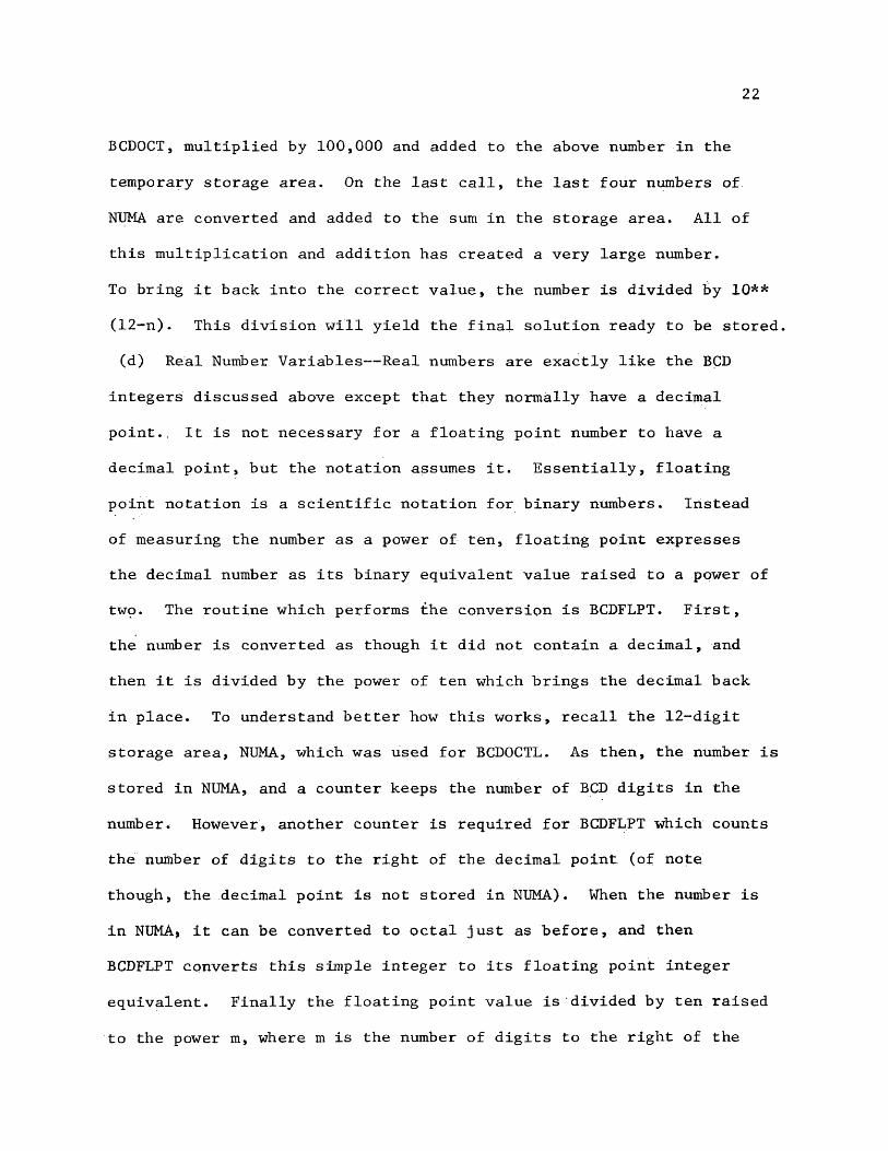
BCDOCT, multiplied by 100,000 and added to the above number in the
temporary storage area. On the last call, the last four numbers of
NUMA are converted and added to the sum in the storage area. All of
this multiplication and addition has created a very large number.
To bring it back into the correct value, the number is divided by 10**
(12-n). This division will yield the final solution ready to be stored,
(d) Real Number Variables— Real numbers are exactly like the BCD
integers discussed above except that they normally have a decimal
point.. It is not necessary for a floating point number to have a
decimal point, but the notation assumes it. Essentially, floating
point notation is a scientific notation for binary numbers. Instead
of measuring the number as a power of ten, floating point expresses the decimal number as its binary equivalent value raised to a power of
twp. The routine which performs the conversion is BCDFLPT. First, the number is converted as though it did not contain a decimal, and
then it is divided by the power of ten which brings the decimal back
in place. To understand better how this works, recall the 12-digit
Storage area, NUMA, which was used for BCDOCTL. As then, the number is
stored in NUMA, and a counter keeps the number of BCD digits in the
number. However, another counter is required for BCDFLPT which counts
the number of digits to the right of the decimal point (of note
though, the decimal point is not stored in NUMA). When the number is
in NUMA, it can be converted to octal just as before, and then
BCDFLPT converts this simple integer to its floating point integer
equivalent. Finally the floating point value is divided by ten raised
to the power m, where m is the number of digits to the right of the

23
decimal. The division is floating point division; hence, the answer
is in floating point notation and ready to be stored (see Figure 3).
A problem alluded to earlier but not discussed was locating
the elements of an array. Now that data has been converted and is
ready to be stored, we have to tell the Interpreter where to store it.
In most cases, the Interpreter can use TABSCAN to retrieve the storage
location of the variable and store the value there, but in the case of
arrays, special calculations must determine the relative displacement
between the first element of the array and the desired element. This
calculation is done by the routine ARRAYLOC (Array Locator) using the
formula:d 6
relative location of element = c( T (x. . ir n.))i=l 1 j=i+l ^
where d is the dimension of the array (limited to six dimensions because
of the Interpreters limit to 12K words of core), x^ is the ith para
meter of the array element, n̂. is the j th parameter of the declared
array as specified in the Declaration Statement, and c is a multiplicative,
constant which indicates the number of words of core used by each
element of the array. The multiple is automatically set to one for
integers and boolean variables, two for real numbers, and the value
in STLGTAB divided by four (plus one for any remainder) for string
characters.Once the interpreter has read all the user's program and
stored the required information for the tables discussed in this section, there are only a few administrative tasks and then, the
Interpreter is ready for the second pass. The first administrative
function is to check to see if the user has requested a data dump.

24
Step 1. The Interpreter first reads the value into a buffer, NUMA, ignoring the decimal but counting the digits. After being read, the buffer and counters will contain the following:
NUMA 1045 3125 0000 with NUMCOUNT 0012 (octal) count for total digits.
DECOUNT 0007 (octal) count ofdigits to the right of the decimal.
Step 2. Next, through three successive calls to BCDOCT, the value in NUMA is converted to octal (ignoring the decimal). Then the number is further reduced by division.
1. First call: 1045 (decimal) 2. Second call: 3125 (decimal)converted to 2025 (octal). converted to 6064 (octal).
575360400 (octal) for 100000000 23420 (octal) for 10000x 2025 x 6064
1412453672400 (octal) 167127500 (octal)
Note: The third call to BCDOCT returns the value zero. Thetwo values are then added together.
1412453672400 (octal)+ 167127500 (octal)1412643022100 (octal)
Step 3. When the calls have been completed to BCDOCT, control returns to BCDOCTL. The above sum is divided by l0**(12-n) where n=10 (decimal).
7623431620 (octal)144 1412643022100
1412643022100Step 4. Now the number is ready to be converted to floating
point, which the floating point value of 7623431620 is 20367623 43162000. Division will be by the floating point value for 10**m, where m=7. This value is 20304611 32000000. The floating point division yields the final value:
20076421 00000000.
Figure 3. Above is an example of the conversion routines, BCDOCTL and BCDFLPT, in operation. Assume the value 104.5312500 is the object for floating point conversion. For the conversion back to BCD, see Figure 6.

It is possible, by using jump switch 6 on the computer console
(see Section III, para 4), to obtain a data dump of all the tables
which should be developed in the first pass. The dump allows the user
to ensure that his tables have been set up correctly before he
continues to the second pass. More discussion will be given on the
data, dumps in Section III. Next, the Interpreter must check to see if
the last card is terminate. If it is not, the program must be
abnormally terminated by the Interpreter, or the Interpreter will not be able.to terminate itself properly during the execution phase.
One final operation must occur before the Interpreter can move
on to the second pass. As an added capability of the Interpreter,
instructions which retrieve data directly from the CDC 3100 system's
data files are provided. When trig functions are used, the value PI
is very frequently desired. By the development of the Interpreter,
the user is required to first declare PI as a variable (real), and
then set it equal to 3.141592654; however, the requirement for PI can
be and is anticipated by the Interpreter. Before leaving the first pass
the Interpreter adds the variable name PI just as though it had been
declared, and literally follows the same routine as other variables
which are formally declared. In addition, the constant value stated
above is placed in its appropriate location in the DATATAB. When using
data from the computer's data base, the same situation again arises. Without intervention by the Interpreter, the user would be required to declare an eighty character string variable; however, since the
^Control Data Corporation, CDC 3100 COMPUTER SYSTEM REFERENCE MANUAL (St. Paul, Control Data Corporation, 1965), p. 7~3Q.

26
Interpreter knows of the requirement, it simulates the declaration
of a string variable (80 characters in length) and gives it the name
STAR. When a line of data is retrieved from the computer’s data base, it is stored in STAR.
Now that all the tables have been completed, the Interpreter
is ready to move to the second pass (see Figure 4).
B. The Second Pass
In the second pass, the Interpreter is ready to begin
execution of the user's program. To enable a sequential execution of
the program, the Interpreter has a program counter, STMTNUM, which
actually contains the first character address of the current
instruction, and a cyclic routine which directs the Interpreter as
STMTNUM steps through the program.
Most program counters are incremented by one after each
instruction because the counter is an instruction counter, but since
the Interpreter must read each instruction character by character to
interpret and execute it, and since the program is stored character by
character, then the program counter will be a character counter. Now
the reader might recall the development of the table STMTTAB (see
Section IIA, para 3), in the first pass which stored the relative
character address of the first character of each instruction. This
table is used to update STMTNUM after the execution of each instruction
until the completion of the program. It should be noted that completion of the program will be indicated by the TERMINATE Statement,
not the end of the STMTTAB table, although both events should occur
at the same time. In some cases, though, the user might end his
program with a TERMINATE Statement which is correct and was checked
27
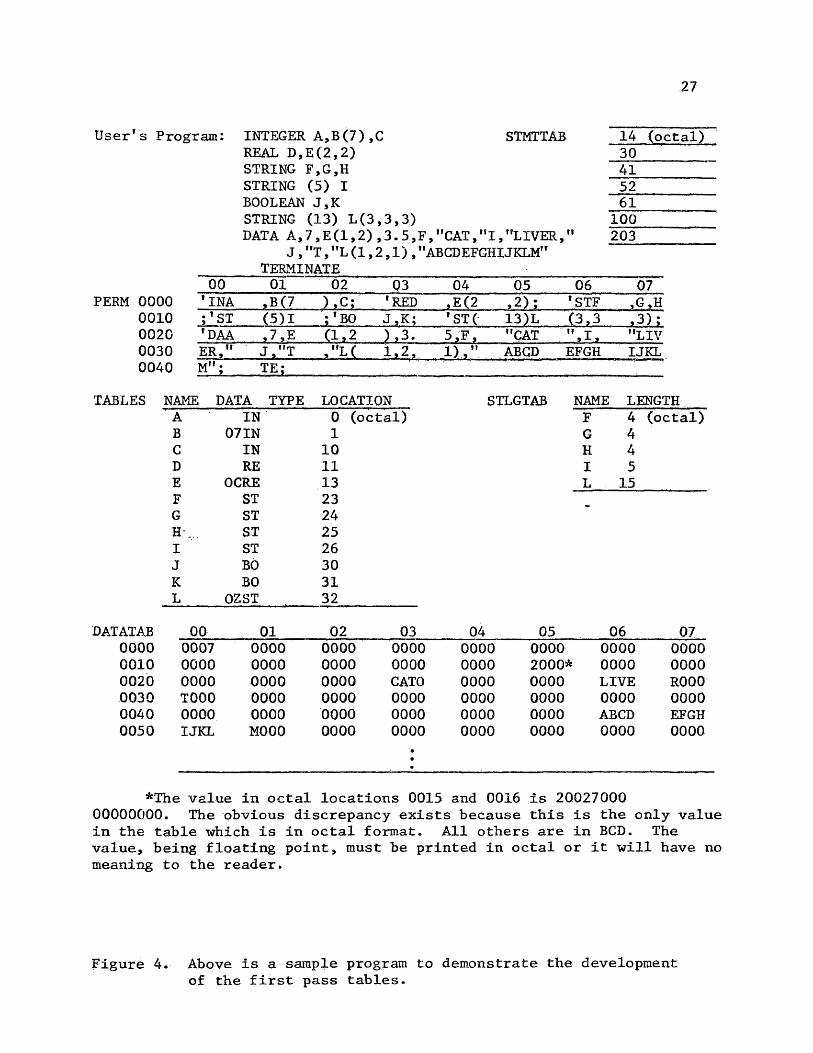
User s Program: INTEGER A, B (7),C STMTTABREAL D,E(2,2)STRING F,G,H STRING (5) I BOOLEAN J,K STRING (13) L(3,3,3)DATA A,7 ,E(1,2) ,3.5,F,"CAT,,fI,rfLIVER,ri
J , "T, f,L (1,2,1), "ABCDEFGHIJKLMfr TERMINATE
14 (octal)30415261
100203
00 01 02 03 04 05 06 070000 * INA »B(7 1, C;I 'RED ,E(2 ,2) ; * STF ,G,H0010 ;' ST (5)1 ; 'BO J.K; ' ST( 13)L (3,3 ,3);0020 tDAA ,7,E a_^2 ),3. 5,F, "CAT " I "LIV0030 ER," J , "T 1,2, 1)," ABCD EFGH IJKL0040 M"; ?Jj
TABLES NAME DATA TYPE LOCATION STLGTAB NAME LENGTH
DATATAB000000100020003000400050
A IN 0 (octal) F 4 (octal)B 07 IN 1 G 4C IN 10 H 4D RE 11 I 5E OCRE 13 L 15F ST 23G ST 24H\ ST 25I ST 26J BO 30K BO 31L 0ZST 32
00 01 02 03 04 05 06 070007 0000 0000 0000 0000 0000 0000 00000000 0000 0000 0000 0000 2000* 0000 00000000 0000 0000 CATO 0000 0000 LIVE R000T000 0000 0000 0000 0000 0000 0000 00000000 0000 0000 0000 0000 0000 ABCD EFGHIJKL M000 0000 0000
•••
0000 0000 0000 0000
*The value in octal locations 0015 and 0016 is 2002700000000000. The obvious discrepancy exists because this is the only value in the table which is in octal format. All others are in BCD. The value, being floating point, must be printed in octal or it will have no meaning to the reader.
Figure 4. Above is a sample program to demonstrate the development of the first pass tables.
28for toward the end of the first pass, but due to some program bug, such
as an infinite loop, his program may not be able to terminate. To
eliminate this problem until the user can correct his program, the
Interpreter will recognize an emergency abort which can be enacted by
the user by depressing jump switch 2 on the CDC 3100 computer console.
The abort will completely terminate the execution of the Interpreter
and return control to the ECDAPS.
Once the first character address of the next instruction has been loaded, the Interpreter begins a character by character search
of the instruction looking for either a single quote or an equals sign.
The single quote (see Section IIA, para 1) will alert the Interpreter
that an instruction type will follow and can be determined from the
next two characters. If the Interpreter finds the single quote, then
these next two characters will be read, the instruction type will be
determined by using the routine DETKMN, and control will be passed to
the routine which evalues and executes the instruction. On the other
hand, if the Interpreter finds the equals sign, then it knows that
an expression is being calculated instead of an instruction being
, so it will be necessary to use a special routine to process
ruction. However, before the expression can be evaluated, the
Interpreter must learn the final storage area for the results of the expression. This information can be found in the argument on the left
side of the expression. The Interpreter has a special routine,EXPRHOME (Expression Home), which will evaluate the left side of the expression and advise the Interpreter of the place to store the
final solution. Now to return to the above discussion, a special
routine must be used to evaluate an expression, but because the
executed
inst

29
evaluation of the Boolean expression differs so greatly from any
other expression, the Interpreter has two routines for solving
expressions. To execute Boolean expressions is BOOLSTOR, and to
evaluate normal expressions is EXPRESN. As the reader might guess,
the expression type returned by EXPRHOME will direct the Interpreter
to the correct routine to be used.
At this point, it should be evident that the Interpreter
deals with only two broad types of instructions: (1) Executableinstructions, and (2) Expressions (see Figure 5). Below will follow
a more thorough inquiry into the mechanics of each of these statement
types.
1. Executable instructions— Executable instructions can be
further broken down into instructions which give directions to the
Interpreter about program execution and into instructions which cause
the Interpreter to make an Input/Output request of the CDC 3100 computer
system. Discussion of these instructions will be offered for the
instructions which direct the Interpreter in the program execution
followed by the I/O request instructions.
(a) Instructions which affect the program execution
1. The TERMINATE Statement— This instruction is probably
the most important to the Interpreter because it indicates that the
job is done. Without this instruction at the end of the program, the
program will not execute, and a diagnostic message will be printed
(see Section IV, para 6). Above it was noted that the user has the
option to~ get a data dump after the first pass. At the end of the
program execution, a similar option also exists. The final chore of
30
X.
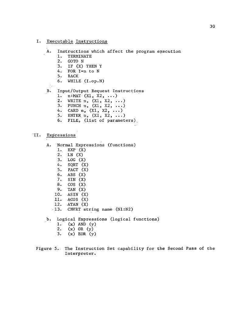
II.
Executable Instructions
A. Instructions which affect the program execution1. TERMINATE2. GOTO N3. IF (X) THEN Y4. FOR I=n to N5. BACK6. WHILE (I.op.N)
B. Input/Output Request Instructions1. n:MAT (XI, X2, ...)2* WRITE n, (XI, X2, ...)3. PUNCH n, (XI, X2, ...)4. CARD n, (XI, X2, ...)5. ENTER n, (XI, X2, . . . )6. FILE, (list of parameters).
Expressions
A. Normal Expressions (functions)1. EXP (X)2. LN (X)3. LOG (X)4. SQRT (X)5. FACT (X)6. ABS (X)7. SIN (X)8. COS (X)9. TAN (X)
10. ASIN (X)11. ACOS (X)12. ATAN (X)13. CNVRT string name (N1:N2)
Logical Expressions (logical1. (x) AND (y)2. (x) OR (y)3. (x) EOR (y)
Figure 5*. The Instruction Set capability for the Second Pass of the Interpreter.

31
the Interpreter after it reads the TERMINATE Statement is to provide
a listing of the source program and if requested, the data dump. If
before the source listing begins, the user decides to request the
full data dump, he may do so by depressing jump switch 1 on the
computer console. On the other hand, if the user decides not to even
get the source listing, in the case of a long program, then once the
listing begins, he may depress jump switch 2 on the computer console,
and the listing will be aborted (for more discussion of data dumps and
dump options, see Section III). Upon completion of the printout
the Interpreter will print a message to the user to indicate a normal
termination of the program.
2. The GOTO Statement— -This statement allows the user to
skip a section of his program which he may not wish to execute in the
normal instruction sequence. The ■format Of the statement isGOTO N
where N is an integer number (less than 999). When the Interpreter
reads N, it uses TABSCAN to determine the character address associated
with the statement number (see Section IIA, para 2), which should have
been stored in the first pass, and then a reverse search through
STMTTAB to locate the address and determine the new pointer to the table. The entire procedure is simply to modify STMTNUM. Obviously,
when a jump is- to be made, the Interpreter is not only concerned with
properly executing the jump, but also with ensuring that the pointer to STMTTAB, which is STMTNUM, is updated so that each statement
executed hereafter is the correct instruction. Once the pointer to

32
STMTTAB is updated, the Interpreter is ready to continue to the next
instruction.
3. The IF ... THEN Statement— This statement gives the
user the capability to execute an instruction (the THEN segment)
providing a preset condition holds (the IF segment), and to skip the
execution of the instruction if the condition does not hold. The
format of this instruction is
IF (X) THEN Y
where X is any logical expression containing two operands separated
by a logical operator, and Y is any executable instruction. The
expression (X), for any two operands, x and y, can make the following
logical comparisons:
(x.EQ.y) X equal to y
(x.NE.y) X not equal to y(x.GE.y) X greater than or equal to y
(x.LE.y) X less than or equal to y
(x.GT.y) X greater than y
(x.LT.y) X less than y
of note is that the logical operators shown above, like FORTRAN,
are flanked on both sides by periods.To actually make the logical comparisons, a special routine,
LEXPRCHK, has been developed. This routine makes use of the normal expression routine, EXPRESN (to be discussed later), to return a
single value of TRUE or FALSE to the Interpreter. Even though EXPRESN
is used, Boolean comparisons are possible because of a specially
designed portion of the two routines (see Section IIB, introduction).
33
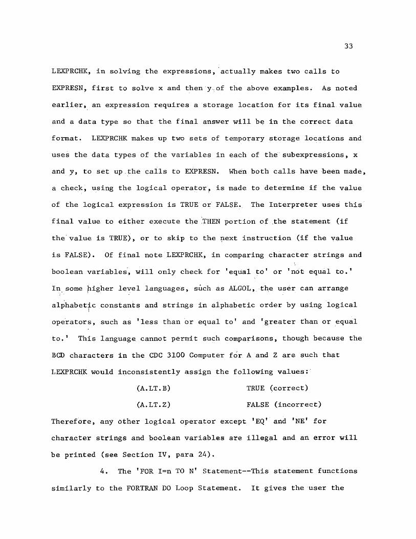
LEXPRCHK, in solving the expressions, actually makes two calls to
EXPRESN, first to solve x and then y,of the above examples. As noted
earlier, an expression requires a storage location for its final value
and a data type so that the final answer will be in the correct data
format. LEXPRCHK makes up two sets of temporary storage locations and
uses the data types of the variables in each of the subexpressions, x
and y, to set up.the calls to EXPRESN. When both calls have been made,
a check, using the logical operator, is made to determine if the value
of the logical expression is TRUE or FALSE. The Interpreter uses this
final value to either execute the THEN portion of the statement (if
the value is TRUE), or to skip to the next instruction (if the value
is FALSE). Of final note LEXPRCHK, in comparing character strings and
boolean variables, will only check for ’equal to' or ’not equal to.’
In some higher level languages, such as ALGOL, the user can arrange
alphabetic constants and strings in alphabetic order by using logical
operators, such as ’less than or equal to' and 'greater than or equal
to.1 This language cannot permit such comparisons, though because the
BCD characters in the CDC 3100 Computer for A and Z are such that LEXPRCHK would inconsistently assign the following values:
(A.LT.B) TRUE (correct)(A.LT.Z) FALSE (incorrect)
Therefore, any other logical operator except *EQ* and 'NE' for character strings and boolean variables are illegal and an error will
be printed (see Section IV, para 24).4. The 'FOR I=n TO N' Statement— This statement functions
similarly to the FORTRAN DO Loop Statement. It gives the user the

34
capability to cycle through specified statements until the number
of cycles, or loops is equivalent to the limit entered by the user.
The format of the statement is as shown, where I is any declared integer ,
variable name (note that this variable must be declared using an
Integer Declaration Statement) which acts as the indice or loop
counter, n is the initial value assigned to I (the value should also
be an integer; however, if n is a real number, since I was declared
an integer, it will be rounded to the nearest integer), and N is the
limit of I; thus placing a limit on the number of loops to be taken.
Unlike FORTRAN, though, the user cannot specify the value by which i
will; be incremented with each loop; the counter, I, will automatically
be incremented by one with each loop.
The Interpreter will allow up to six nested loops; that is,
only six loops may be used at one time. The organization of this
statement by the Interpreter is not very involved and relatively
uncomplicated. The Interpreter maintains a table which contains
the relative address (relative to DATATAB) of the counter’s storage
location (determined by TABSCAN), a table which contains the final value, or limit, of the counter, and a table which contains the
character address of the first statement following the ’FOR1 Statement.
The construction of these tables enables efficient processing and
execution of the 'FOR’ Statement. Finally, the ’FOR’ Statement
requires another statement which acts as a delimiter to the loop. This
additional statement will indicate to the Interpreter that the end of
the loop has been found, and the Interpreter must either execute the
instructions of the loop again, or close the loop and continue to the

35
next instruction. The statement referred to here is the BACK
statement.
5. The ’BACK* Statement— This statement, as stated above,
signals the conclusion of a set of instructions. This conclusion will
be either to a group of instructions involved in a ’FOR' Statement
loop or a 'WHILE1 Statement loop. The format of the Statement is as
shown above. The. statement has no formal parameters.
When used with the 'FOR1 Statement, the ’BACK' Statement will
cause the Interpreter to examine the tables developed by the ’FOR'- /
Statement and do one of the following things.
(a) - If the value of the counter, I, has not yet reached its limit,
the Interpreter will retrieve the relative character address of the
statement following the 'FOR* Statement and transfer it to the
instruction which begins the loop 'again. Just prior to transferring,
though, the counter, I, will be incremented and restored.
(b) If the value of the counter, I, is equal to its limit, then the Interpreter will close the loop, by decrementing a counter to
the tables, and continue to the next executable instruction.
(c) If the value of the counter, I, exceeds its limit, then the user
must have incorrectly used the fFOR' Statement. Most likely, such an
error would be initializing the value of I, n, to be a value larger
than the limit., N. In such a case, an error message will be printed
for the user (see Section IV, para 18).
When used with the 'WHILE' Statement (to be discussed later)
many of the above actions will take place. In particular, though,
since the variable in the 'WHILE' Statement is not automatically
36
incremented with each loop, the ’BACK' Statement must also check to
see if the variable is converging to the limit, If not, the computer
verges on an infinite loop, and the program must be aborted. To
coordinate this, the Interpreter uses the computer’s internal clock
to limit the loop execution time. If the program must be aborted, an
error message will be printed to the user (see Section IV, para 26).
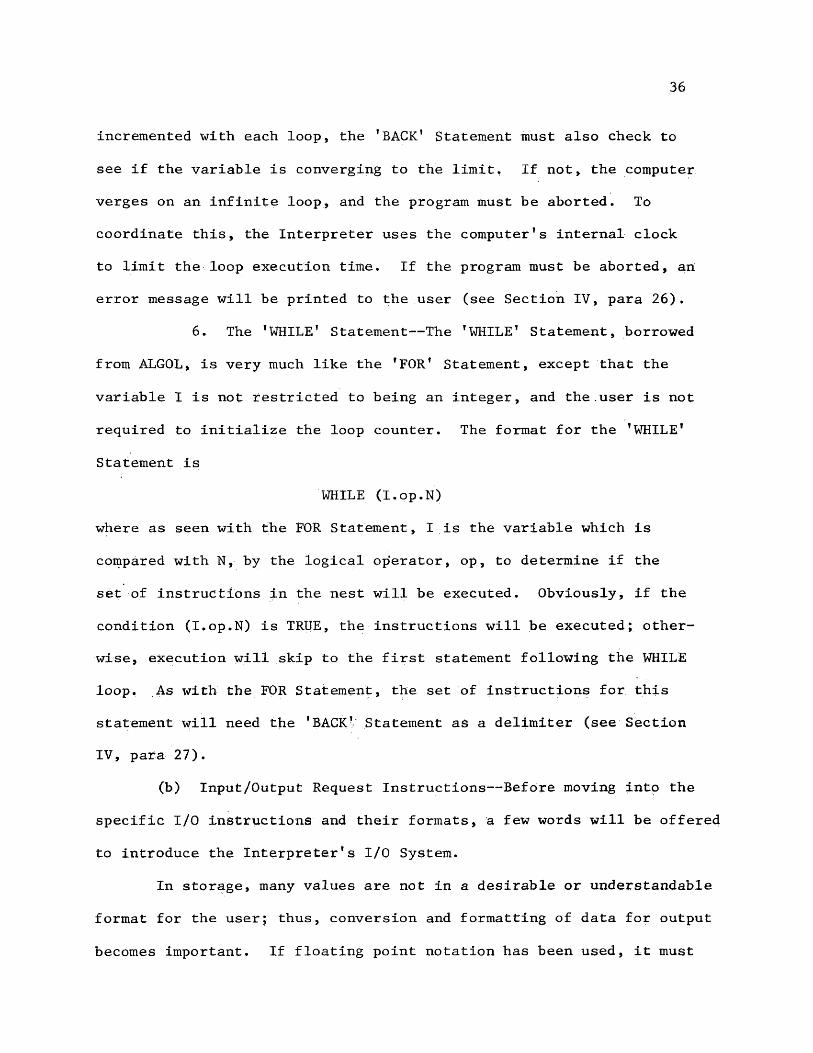
6. The ’WHILE’ Statement— The ’WHILE’ Statement, borrowed
from ALGOL, is very much like the ’FOR* Statement, except that the
variable I is not restricted to being an integer, and the.user is not
required to initialize the loop counter. The format for the ’WHILE’
Statement is
WHILE (I.op.N)
where as seen with the FOR Statement, I is the variable which is
compared with N, by the logical operator, op, to determine if the
set of instructions in the nest will be executed. Obviously, if the
condition (I.op.N) is TRUE, the instructions will be executed; otherwise, execution will skip to the first statement following the WHILE
loop. As with the FOR Statement, the set of instructions for this
statement will need the ’BACK’ Statement as a delimiter (see Section IV, para 27).
(b) Input/Output Request Instructions— Before moving into the
specific I/O instructions and their formats, a few words will be offered
to introduce the Interpreter’s I/O System.
In storage, many values are not in a desirable or understandable
format for the user; thus, conversion and formatting of data for output
becomes important. If floating point notation has been used, it must

37
be converted to its real number equivalent (in BCD) before printing;
if the number is octal, it must be converted to decimal since most
people do not work with octal values; and if it is in string notation,
the data is stored in the correct format, but it must receive proper
handling for printing according to its specified string length.
To do the above important tasks are two routines for data
conversions and three routines for data formatting. First we will
discuss the data conversions.
For real number values stored in floating point notation, the
routine FLTDEC (Floating Point to Decimal Conversion) is used.
FLTDEC actually performs the conversion in two parts: first, it
converts the floating point number to its integer value (BCD) without
the fraction and stores it; then it finishes the conversion by processing
the decimal portion which is preceded by a decimal and stored behind the
BCD integer. The BCD integer is arrived at by unfloating the real number into an octal integer and fraction; the fraction is placed in
temporary storage. The integer then is converted to BCD by dividing it by the largest possible power of ten (such that the resulting quotient
be greater than one but less than ten), where the quotient represents
the leftmost significant digit, and from there by continually dividing
the remainder of the previous division by the next smallest power of
ten, to produce each additional significant digit (from left to right),
until the divisor becomes one. When the divisor is one, the integer
conversion is complete. At this point, the fraction is retrieved from
its storage area, and converted to a decimal fraction by continually
multiplying the fraction by ten (decimal) until the desired accuracy

38
(seven places) is achieved. Each multiplication produces one
significant digit (from left to right), where the significant digit will' )
be found to the left of the decimal. As the reader can see, the
routine is complicated, particularly when dealing with negative numbers
and decimal numbers (less than abs(l)); however, without it, the
Interpreter cannot provide the user with a meaningful answer.
Another such routine within the Interpreter is FLTBCD (Floating
Point to BCD Conversion), which converts octal integers to BCD decimal
integers. From the above paragraph, it should be noted that the
Interpreter was tasked with converting the floating point number to an
integer (decimal) and a decimal (fraction) number; thus, conversion
of integers is identical to real number conversions except the
fraction is excluded. So the integer conversion will Use the same
technique and the same routine, FLTOCT, initially, but if there is any
fraction, it will be rounded off to the nearest integer (see Figure 6).
Now that the data has been converted to the correct data
structure for printing, the user must be concerned about the output
format. Otherwise, there will be times when the computed format
will appear messy and inadequate to the user. For example, the
Interpreter in converting real numbers to BCD format, uses the standard
seven digits on each side of the decimal. If the user is working in
dollars and cents, he will most likely only want two digits to the
right of the decimal; another case is for small numbers, the Interpreter
fills out the value with leading and trailing zeros, which the user may
or may not want in his printout. Therefore, because at times the user
will not be satisfied with the computer's format, and at other times,

39
Notes Initially, it will be assumed, that the value 20076421 00000000 is already in storage waiting to be converted to BCD format for printout purposes.
Step 1. Unfloating the floating point number yields:
150.42.Retain the 150; temporarily store the 42.
Step 2. Next the number is converted by digit through division. The number is divided by the largest power of ten which produces a quotient greater than one but less than ten. The single digit quotient is a significant digit in the conversion and is saved, while the power of ten is reduced one place as a divisor for the remainder of the previous division. Continue dividing in this manner until the power of ten is zero.
a). Dividing by 144 (octal for decimal 100) yields: 1
144 1150-144
4b). Dividing by 12 (octal for decimal ten) yields:
o '12 14
-04
e). Dividing by 1 (octal for decimal one) yields:4
1 !4-4 0
Step 3. Next place the three digits from the calculations above in order to form 104. At this point, FLTBCD, for integers, rounds off the fraction (.42 (octal)), and returns the BCD integer value 105.
Step 4. Multiply .42 (octal) by 12 (octal for decimal ten) seven consecutive times as below to determine the decimal fraction.
1. .42 2. .24 3. .10 4. ,20 5, .40 6. .00 7. .0012 12 12 12 12 12 12
5.24 3.10 1.20 2.40 5.00 0.00 0.00
Step 5. The final step is to place the leftmost digits from each multiplication above with the 104 to arrive at the BCD value
104.5312500.
Figure 6. Above is an illustration of the FLTDEC and FLTBCD routines which prepare data for the user’s eyes.
40
he will want to use the computer’s format, the Interpreter provides
the option of either formatting or not.
Whether format statements are used or not, the Interpreter begins
its analysis in the same way. First, the Interpreter reads the
statement to look for a statement number. If it finds one, the number
is stored for later use. If not, a flag is set to indicate that no
format statement is being used. Then the Interpreter transfers to a
routine DATAREAD, which finishes reading the I/O Instruction to
identify which data variables are required for the printout. DATAKEAD
creates a table, I0REQ, to store the data type, the storage location of
the data item to be processed, and when a string variable, the
string length. In the case of arrays, the absolute address is
calculated and stored, rather than storing the array’s first element
word address. Once the table is established for the line to be printed,
the Interpreter moves to another routine, MATEVAL, which actually
constructs the line for output. Before this second routine gets
started though, it checks for the statement number, which, if it
exists, would have been stored earlier. If there is a statement number,
then the line cannot be constructed until the MAT Statement is evaluated
so that guidance will be available for MATEVAL. To perform this
evaluation, the routine MATSTA has been developed. MATSTA, first of
all, determines the location of the MAT Statement (using TABSCAN,
see Section IIA, para. 2); then, it makes a character by character
replica of the desired output line, using only characters (X— for
blank, R— for integer portion of real number, D— for decimal of the
real number, F---for fraction of the real number, C--for character

41
strings, and I— for each integer digit) instead of the actual values.
Later, MATEVAL will use this replica to determine the exact location
to store blanks, numbers (also paying attention to the size of the
number in digits to be printed), and character strings. Once the
replica line has been constructed, MATEVAL uses the table constructed
by DATAREAD to retrieve each data item listed; it uses the conversion
routine discussed above to put the data in the correct format; and
finally, it overwrites the replica line according to the placing of the
format characters on the line. It should be noted that the Interpreter does not actually overwrite the replica line, but writes in parallel
to another buffer area of the same size. Overwriting the replica line would lead to problems because the nature of the procedure described
above implies that the Interpreter must scan the replica line in■'l
search for X's, R ’s, D\s, F fs, C's, and I1s. Assuming that a character
string is part of the output, if a second line were not used for the
data, the Interpreter would be hard pressed to separate actual data
items (characters) from the format notes. The difficulty is not worth
the extra core saved by using only one buffer. Thus this problem is
avoided by storing the character string label in the second buffer
(the buffer which is actually printed). Since the label was to appear
in this location in the second buffer anyway, no harm is done, and much
confusion is avoided. In accordance with the above discussion of format
statements, the format of the MAT Statement is introduced below:
n: MAT (XI,X2,...)
where n is the statement number followed by a colon, and (XI, X2,...)
is made up of any data formats using the cases as illustrated below:
(a) Fw.d— where w is the field length (including the decimal), and
d is the number of characters to the right of the decimal.
(b) Iw— where w is the number of digits in the integer to be
printed.
(c) Cw— -where w is the number of characters in a string to be
printed.
(d) nX— where n specifies a certain number of blanks to be printed.
Of course, as noted earlier, F, I, C, and X must appear as part of the
field length information to identify the data type for MATEVAL.
Next to be considered is the case when a format statement
has not been used. If no Statement number is indicated in the I/O
Instruction, then the Interpreter is saved some analysis, but it does
not escape totally free from the spell of formats. Although not
officially entered by the user, when no format statement is used, the
interpreter must still supply an output format. In this instance, the
data to be printed can only be taken directly from storage and dumped;
thus, the concept of a standard format is begun.
Even though no format statement exists, as noted earlier,
the Interpreter wihl still go through DATAREAD to set up the table of data types, storage locations, and string lengths. From DATAREAD, the
Interpreter goes to MATEVAL, but since there is no format number, the
Interpreter will not use MATSTA. Since no direction is provided from
MATSTA, it is necessary to keep a column counter, or tab counter, to
43
keep abreast of where each data value is to be stored. As these
values are stored, the tab counter will increment accordingly to move
down the line as the Interpreter moves through the table which was
produced by DATAREAD. Obviously, some form of spacing must be used.
The Interpreter automatically assigns four words of storage to real
numbers and to integers. Since the format of these data, items is
unadjusted, they will be printed in long form; that is, integers will
be seven digits (with leading zeros), and real numbers will be fifteen
digits (with leading and trailing zeros). Character strings will be
stored in their entirety, and the spacing will be a skip to the end of
the current word and then skip one full word. The character string
skipping is irregular because the Interpreter does not readily know where
the address of the next word of buffer storage is. Therefore, it must
divide a character by four, round the quotient, and add one word to
ensure adequate spacing. (For examples of the I/O System, see Appendix
A).Now that the user has seen how the I/O structuring operates
for output, discussion can turn to the actual I/O Instructions which
make use of the above concepts:
1. The ’WRITE1 Statement— This instruction provides the user with the capability to make I/O data requests of the printer.
As was seen above, the option to use or not to use format statements
exists. The format of the WRITE Statement is:
WRITE n,(XI, X2,...)
where n is the optional statement number of the format statement
used, and (XI, X2,...) are the data variable names for the quantities
44
to be printed (the parentheses are optional). The data variables
can be any type; they can also be in array format. The routine DATA-
READ, as discussed above, will properly handle the data type, data location, the string length where applicable, and store the information
in a table.
2. The ’PUNCH’ Statement— The PUNCH instruction is identical
to the WRITE Statement except that the output peripheral is a card
punch instead of a line printer. The format for this instruction is:
PUNCH n, (XI, X2,...)
where the above symbols are as represented in the WRITE Statement.
As above, where it was necessary to prepare, through conversion
routines and formatting routines, the data in storage for the user’s
eyes, now it is necessary to consider the reciprocal operation; that
is, preparing input data for the computer's eyes. The process is not
to differ greatly from the above method of converting the output
data; however, just by the fact that the data is moving in a different ‘
direction means that additional routines are necessary. For example,
the Interpreter cannot very well convert BCD quantities to binary
(octal) or floating point values by using the same routine which
Converts from floating point and binary to BCD. In the same manner,
instead of using MATEVAL which stores information to a line in its
final format ready for print, a different routine will be required
which will take the data from the line as read into the computer,
convert it to its proper format for computer use, and store it in its
proper storage location in DATATAB. Therefore, it is necessary to
45
determine what parts of the current I/O system can be salvaged for
input, and what parts must be developed.
As stated above, different routines will be needed to convert
the data structures recognized by the computer. Fortunately, these
routines have already been developed for use in the DATA Statement
(see Section IIA, para 4), They are BCDFLPT, which converts the BCD
real number into its floating point equivalent, and BCDOCTL, which
converts a BCD integer value into its octal equivalent. Therefore, it
is only necessary to read the line of data and determine what value is
to be converted, use the above routines to convert it, and then,to
store the data. First let us consider the storage of the data. As was discussed earlier, to store data which is in BCD format, the
Interpreter must have a data type and data storage location. Now the
reader might recall that the Interpreter constructed a table, using the routine DATAREAD, which contained precisely the needed information for
data storage. DATAREAD was introduced as a routine which stored
the type, storage location, and character count of string variable for
output conversions, but the same routine will now be used to store the
data type, storage location, and string length for input. The obvious
difference will be in the next step where different conversion routines
will be used depending upon whether the operation is input or output.
Thus the real change to be made will be in the routine which causes
the data conversion. To carry the thought one more step, another
difference is the final destination of the data storage; one case will
.cause data to be stored to a buffer for printing or punching, while the
other case will cause the data to be stored to the computer's data

46
tables for future processing* In the output mode, the routine which
converted and stored the data was MATEVAL. Thus, for the input
operation MATEVAL must be the routine to be replaced, or actually, to
be redone to reverse the direction of the data. The replacement
routine will be MATINPT, which will follow DATAREAD, and use the
table established by it* In addition the system will use the routine
MATSTA, which, as the reader will recall, constructs a replica line
of the format line, if used. Then these three routines together
will get data from the input queue of the computer to the correct
storage location in the data tables. In cases where no format is used,
the Interpreter will just read the information and recognize commas
as data delimiters.
Now that the user has seen how the I/O is done for input,
it is time to turn to the instructions which will cause the above
concepts to be used.
3. The VGARD* Statement— This instruction will give the
user the capability to enter data with cards. The structure of this
statement is:/
CARD n, (XI, X2,...)
where n is the optional format statement number, and (X1,X2,...)
are the data variable names which indicate the storage location for
the input data. Of note, the parentheses above are optional in
all of the Input Routines as they were in the Output Routines.
4. The 1 ENTER* Statement— This instruction provides the
user with the capability to enter data into the computer from the
console typewriter. The format of this instruction is:
47
ENTER n s (XI, X2 ,...)
where the symbols used are identical with the ones used in the
CARD Statement.
Thus far, the Interpreter has dealt with computer input and
output in terms of its peripheral equipment, such as the printer, card
reader, card punch, and the typewriter. However, there is one more
I/O instruction to be considered. A major feature of the Interpreter
is that the user will have access to the data base in the computer.
To make the data retrieval, it is necessary to use two routines of
the ECDAPS Software System; one is QUERY, which when supplied with a
list of parameters for data retrieval options, will search the data base and bring the desired data into a buffer of the computer. Output
from QUERY to the Interpreter can call up the data line by line for
the user. All subsequent calls for a line of data is coordinated by
the ECDAPS routine DATA, which updates the pointer to the data buffer.
After each line of data is read, it is necessary to update the pointer
to the next line.
Normally the Interpreter acts as the middle man between the
user and the ECDAPS Software System. Thus, a routine must be
developed to. enable the user to define his data needs of the system and
to state those needs to the two ECDAPS routines to be used. To better
understand what such a routine must look like, it will be necessary to
understand a few things about the data base of the computer. Since
the data is classified military information, it will not be possible
to discuss in great detail the purpose or design of the data. However,
it is important for the reader to understand that the computer is a
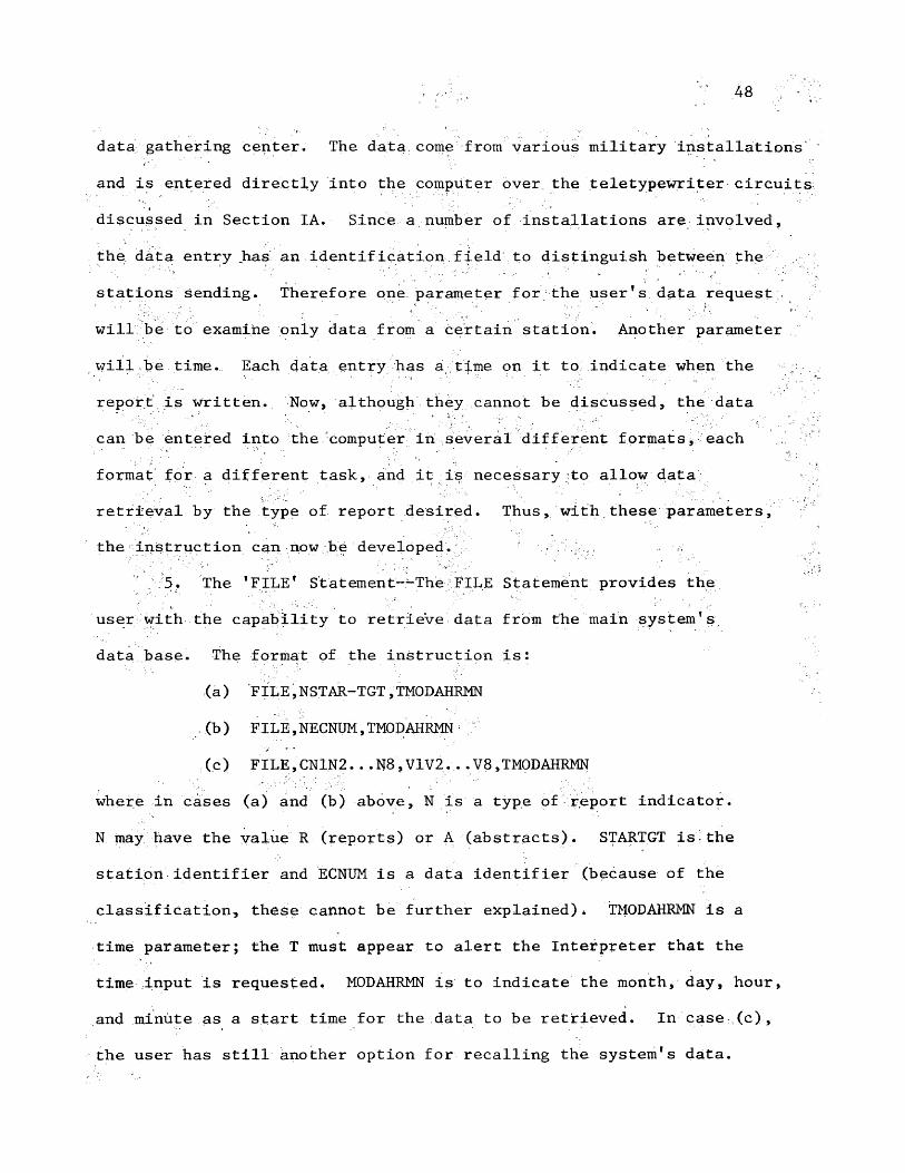
'• " 48 > :'v.
data gathering center. The data, come from various military installations
and is entered directly into the computer over the teletypewriter circuits
discussed in Section IA. Since a number of installations are involved,
the data entry has an identification field to distinguish between the
stations sending. Therefore one parameter for the user's data request
will be to examine only data from a certain station. Another parameter
will be time. Each data entry has a time on it to indicate when the
report is written. Now, although they cannot be discussed, the data
can be entered into the computer in several different formats, each
format for a different task, and it is necessary to allow data retrieval by the type of report desired. Thus, with these parameters,
the instruction can now be developed. - ■5. The 'FILE' Statement---The FILE Statement provides the
user with the capability to retrieve data from the main system's
data base. The format of the instruction is:
(a) FILE,NSTAR-TGT,TMODAHRMN
.(b) FILE,NECNUM,TMODAHRMN;
(c) FILE,CN1N2...N8,V1V2... V8,TMODAHRMN
where in cases (a) and (b) above, N is a type of report indicator*
N may have the value R (reports) or A (abstracts). STARTGT is the
station identifier and ECNUM is a data identifier (because of the
classification* these cannot be further explained). TMODAHRMN is a
time parameter; the T must appear to alert the Interpreter that the
time input is requested. MODAHRMN is to indicate the month, day, hour, and minute as a start time for the data to be retrieved. In case (c),
the user has still another option for recalling the system's data.
49
Because the data is in the form of an 80 column string (see Section
IIA, closing remarks), the data can be requested based on stated
column values. The columns to be compared will be N1N2...N8 (note no
comma between column numbers), up to 8, and the values to be compared
against for the respective columns will be V1V2..,V8 (again no comma).
Of note, the values specified by should be only one digit even though
they are implied to be two digits.- With this capability, the user
can request to see all lines of data in the computer with a 3 in column
27 by using the instruction FILE,C27,3.So that the reader will not be confused by use of this
instruction, an explanation must be given. From above, it seems that
the instruction will load an entire buffer of data into an area for the user to use. This is not the case. The buffer has been loaded by
QUERY for the Interpreter to use, but due to the limitation on storage
for the Interpreter, it is not possible for the Interpreter to load
this data for the user. Instead, the FILE instruction causes a single
line of data to be loaded. For more data, it is necessary to loop
through the instruction each time a new line is required. Now, an
obvious way for the user to override the Interpreter’s intent here to
conserve storage is to declare an 80 column string array, read a line of data and store it in each successive element of the array. However,
when a line is called up, it is automatically stored in an area set
aside by the Interpreter (STAR), and can be operated on from that special location. The desirable method to use the FILE instruction
capability is to read a line of data, operate on it, and return for
another line. In this way, the user can still use the data without
50
tying up the InterpreterTs storage area. To loop the FILE instruction
as recommended, the Interpreter has developed a special technique to
continue reading data until the end of file is reached. The loop
should look like this:
WHILE (STAR.HE."T")
FILE,(followed here by requested parameters)
BACK
«
TERMINATE
As can be seen, the Interpreter performs the loading operation
with the WHILE Statement. Once the last line of data has been found,
the Interpreter enters the letter TT* in the first character position
of STAR.
6. The 1 SCRATCH1 Statement— -The simple function of this
command is to void the current file of data, which had been earlier
retrieved, when the user is ready to fetch new data. After this
statement, the user can reinitialize his QUERY parameters. Then,
when he specifies the new parameters in another 'FILE* Statement,
the new buffer of data can be loaded.
Now that the I/O instructions have been discussed it is
time to look at the instructions and functions which revolve around
the Interpreter1s expressions. Since the computer is filled with
calculations3 the solving of expressions is highly important.

51
2. Expressions— Developing a method to solve expressions
is extremely complex because expressions can be simple involving no
variables, or cumbersome involving variables, functions, or just a
combination of these. They may be long or short, with parentheses or
without. In each case, one routine must be able to accommodate the
problem. The first task for the Interpreter to handle when
confronted by an expression is to determine the expression’s home; that
is, once a final solution has been calculated, the Interpreter must
know where to store it and in which data form. Thus as was stated in
the introduction to the Second Pass, a routine, EXPRHOME, will read
the name of the variable, including arrays, on the left side of the
expression, and determine and store the location of the variable and
its data type.
Once the location and type are known, it is necessary to
tackle the right side of the equation; however, because the calculation
of expressions are handled differently in the case of Boolean variables
it is necessary to have two techniques to solve expressions* Thus,
discussion of each of these routines will follow.
(a) Normal Expressions-— The routine to solve normal expressions,
EXPRESN, is divided Into two main parts; one, EXPRESN, has the capability to solve expressions which have both real numbers and integers contained within it, and two, EXPRESN can process string
variable assignment statements.
... First, let us consider the string variable assignments.
A string variable may be assigned a value either by giving it the
value of a string constant which is enclosed in double quotes, or by

52
setting it equal to another string variable. Therefore, if the
Interpreter, in scanning the expression, finds a double quote, it knows
immediately to store the characters following as the string’s value.
In the other case, if the string variable is set equal to another
string variable, the Interpreter simply copies the characters fromthe first location in core to the new location. As is readily seen,
this first type of expression can be easily handled by the Interpreter.
The solving of this string variable problem is accomplished primarilyby allowing the Interpreter to utilize programming designed for the
second type of normal expression.
A major feature of the Interpreter in dealing with character
strings is the capability given to the user to work with partial
strings. This means that the user may print just part of the string
variable, or in an assignment, he may give it the value of only part4of another string. The feature exists in ALGOL W ; it cannot be found
in FORTRAN or most other scientific languages. The notation adopted
by the Interpreter to indicate a partial string is
STR (N1:N2)
where STR is the string variable name, N1 signals to the Interpreter
to skip the first N1 characters, and beginning with Nl+1, use the
next N2 characters.In the second type of normal expression, the Interpreter is
much more involved with the expression. In the previous type, the
Interpreter was concerned with relocating data from the expression
^Sites, Richard L., "ALGOL W Reference Manual," (Stanford University, 1972), p. 40.

53
or from a location in storage to the location of the variable being
assigned the value. In this problem, though, the Interpreter deals
with arithmetic expressions which may be nested in parentheses and which
may contain many variable names and arrays. In either case, the
Interpreter must break the expression down into simple, easily solvable
components of the original problem. In undertaking this task, the
Interpreter first scans the line in search for each data element
(variables, constants, and functions). As each element is discovered,
it is converted into its floating point value; that is, variables
are retrieved from storage, and if required, are converted, and
constants are all assumed to be real numbers and are automatically
converted to floating point.. When these floating point numbers are
arrived at, they are stored in a table called VALU. Since a floating
point number requires two words of core, the relative address of
these in VALU are 0, 2, 4, ..., which in BCD will be 00, 02, 04,...,
respectively. As the values are being stored in VALU, the Interpreter
is rewriting the expression by replacing each value by its relative
address in VALU, but without changing the symbols and other notation
of the expression. Below is an example of how this process works:DEMO = (3.0+ARA(2,3))*7-VAR**EXP
where ARA(2,3)=2 and VAR =4and EXP =6
From rewriting the expression as described above, the result is
=(0+2)*4-618 where VALU 20026000 00000000+2 20024000 00000000+4 20037000 00000000+6 20034000 00000000+8 20036000 00000000
54
Note .that the symbol for exponentiation, **, is rewritten as a t.
This is deliberate. From close observation of the rewritten expression
above, the reader will note that the line can now be reread, and the .
Interpreter will with each character load the address of a value, or a
parenthesis, or an arithmetic operator. With the new structure, the
Interpreter has surpassed the problem of character names and lengths
as well as variable and value string length. Next, higher level
languages deal with the execution priority sequence. Usually they
will execute everything in parentheses first, then they will execute
each operation on the line according to the operator priority. Thus
the Interpreter will execute everything in parentheses. It will
accomplish the task by reading and storing the expression. Whenever
a begin parenthesis is encountered, the Interpreter forgets what it
has read, and from the point of the new parenthesis it begins to read
and store the remainder of the expression. Whenever an end parenthesis
is encountered, the Interpreter solves whatever portion of the
expression has been stored at that point. When the expression within
the parenthesis has been calculated, the final value determined will be stored in VALU in the lowest relative address of this mini-expression,
and the expression will be rewritten, only this time, with one less level of parentheses. When the Interpreter does not find any
parentheses, it will run into the semicolon stored at the end of the
instruction by PREPROC, and then it will solve the expression which has
been read. When more than one operator is in an expression, priority
is given in the following order: **>/»*»+,-• Within the example
given above, the final solution would be derived as follows:

55
=(0+2)*4-6f8 (0+2) is evaluated and stored in 0=0*4-618 ' 618 is evaluated and stored in 6=0*4-6 0*4 is evaluated and stored in 0=0-6 0-6 is evaluated and stored in 0=0 Final value will always be in zero
From the breakdown given above, the two points are worth noting;
first, the final will always be in relative address 0 in VALU, and
secondly, the Interpreter does not require four passes through the line
to solve such a trivial problem. The Interpreter requires one pass to
rid the expression of the parentheses, and one pass to solve the problem.
One part of expression solving which has been ignored until now
is function processing. When the Interpreter comes across a function
request such as TAN, SQRT, etc., it must come up with a quick evaluation^
of that expression before it can continue to the actual mechanics of
expression solving which were discussed above. Thus before moving on,
it is necessary to jump back to discuss the functions which come with
the Interpreter, and how they work.
1. EXP (X)--This function solves the problem, e**X, where
e=2.718281828. The Interpreter arrives at the value by a method of
series expansions’* through the first sixty expansions. The equation is0 1 2 59Y y Y Y
EXP (X) = -5T- + -l r + ~2j- + ... + -jgT .The expansion is carried so far, because when dealing with real numbers,
the Interpreter calculates the solution to seven decimal places.In problems where X is extremely large or small, the seven place
accuracy can be obtained only by going through sixty expansions.
^National Book of Standards, Handbook of Mathematical Functions With Formulas, Graphs, and Mathematical Tables, ed. by Milton Abramowitz and Irene A. Stegun (Washington, D. C.: U. S. GovernmentPrinting Office, 1964), p. 69.
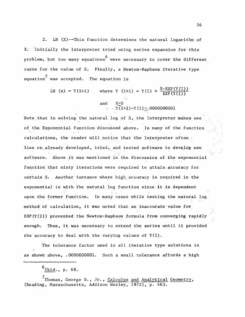
56
2. LN (X)-— This function determines the natural logarithm of
X. Initially the Interpreter tried using series expansion for this£
problem, but too many equations were necessary to cover the different
cases for the value of X. Finally, a Newton-Raphson Iterative type equation^ was accepted. The equation is
LN (x) = Y(I+1) where Y (1+1) = Y(I) +
and X_<0Y (I+ 1)-Y ( I ) <_. 0000000001
Note,that in solving the natural log of X, the Interpreter makes use
of the Exponential function discussed above. In many of the function
calculations, the reader will notice that the Interpreter often
lies on.already developed, tried, and tested software to develop new
software. Above it was mentioned in the discussion of the exponential
function that sixty iterations were required to attain accuracy for
certain X. Another instance where high accuracy is required in the
exponential is with the natural log function since it is dependent
upon the former function. In many cases while testing the natural log
method Of calculation, it was noted that an inaccurate value forEXP(Y(I)) prevented the Newton-Raphson formula from converging rapidlyenough. Thus, it was necessary to extend the series until it providedthe accuracy to deal with the varying values of Y(I).
The tolerance factor used in all iterative type solutions is
as shown above, .0000000001. Such a small tolerance affords a high
^Ibid., p. 68.
^Thomas, George B., Jr., Calculus and Analytical Geometry, (Reading, Massachusetts, Addison Wesley, 1972), p. 463.

57
factor of accuracy for all calculations. It should be brought out
that whereas the Interpreter only prints the solution to seven
decimal digits, often the final output will be varied by the lower
order values. In use of floating point notation, the Interpreter can
express up to twelve digits of a number. These digits may be to the
right or left of the decimal; however, more often than not, the
Interpreter will be calculating numbers to the ninth and tenth decimal
place. Therefore, in discussing the accuracy of calculations, many
times the Interpreter is dealing with the lower order values which may
not be printed, but obviously affect the final solution.
3. LOG (X)--This routine will calculate the common logarithm
of X. The method is very simple using the identity
LOG (X) = (2.302485093) * LN(X)> X>0.Again the reader can see where the preciseness.all the way back to
EXP (X) will be required just to calculate the common logarithm of X.
4. SQRT (X)— This routine will calculate the square root of
X. As might be expected, the solution is determined by using the
famous Newton-Raphson method of iteration. However, as the reader has
been told, the Interpreter, whenever possible, will make use of already
developed technology for continued developments, so the decision had
to be made as to whether to use the exponentiation of X to the one
half power. The problem was quickly resolved by the examination of
the two techniques. Whereas in every example tested (see Appendix B),
the,solutions were identical, the Newton-Raphson method proved itself
quicker in reaching the final solution. It was interesting and
reassuring to note that each method, even though completely different

.58
Software was used for each, produced the identical value to the seventh
decimal place. The Newton-Raphson iteration formula for the square root is
y_y(tY2SQRT (X) = Y (1+1) where Y(I-fl) = Y(I) +
and X>_0Y(I+1)-Y(1)^.0000000001
5. FACT (X)— This function will calculate the factorial of X.
The routine begins with X, decrements by one,:and multiplies the two to
arrive at the product. Then, it continues to decrement the value of
X by one, multiplying the new number by the previous product, which
yields a new product, and continues through the cycle until X becomes
equal to one. Then the final, value has been found. Of note, X must be
a positive integer, or an error will result (see Section IV, para 13).
The equation isFACT (X) - (X)(X-l)(X-2) . . .(1), where X is a positive
integer.
6. ABS (X)— This routine determines the absolute value of X.
The determination is made according to the following relationships
. ’ lX=X for X positive or zeroABS (X) = J
(x=-X for X negative7. SIN (X)— This routine will calculate the sine of X by
■ t gusing the series expansion method. The formula is
Y 1 Y 3 Y 5 Y 7 Y 9 Y 11SIN (X) « - 5- - - + -------- - +-------l! 31 5! 7! 9! ll!
^Ibid., p. 822.

59
Note that the series is alternating in sign; also note that the series
is expanded only to the sixth expansion. The series is short because
it provides a quick and highly accurate convergence to the solution.
An additional capability to the user which is not immediately
obvious is that the function has radian or degree input available.
If the user wishes to exercise the radian input option, he can precede the parentheses with an R; otherwise degree input will be assumeid.
8. COS(X)— This routine will calculate the cosine value of X;9 •The series expansion technique is also used with cosine, and the.
formula is ;X° X2 x4 X6 X8 x10COS (X) = -qT- - - T - +. “ T~ - -gT- + -gT 10T
Note here also that the series has an alternating sign, and it too
is expanded only to the 6th element. Although it should not need
mention, the cosine function has the Same option for radian and
degree input as the sine function.
9. TAN (X)— This routine will calculate the tangent of X.
For this value, it is simple for the Interpreter to determine the sine
and cosine values of X and use the following relationship
TAN (X) =Of note, the tangent function has the same restrictions and
advantages as it constituents sine and cosine.10. ASIN (X)-—-This routine calculates the arcsine, or inverse
sine, of X. The value is calculated using the Newton-Raphson
iterative technique. The formula is
^Ibid. , p.. 823.

ASIN (X) = Y(I+1) where Y(X+1) = Y(I) +
and Y (I+1)-Y(I)_<. 0000000001-1_<X<1
11. ACOS (S)— This routine calculates the value of the
arccosine, or the inverse cosine, of X, again with the ASIN function,
by using the Newton-Raphson method of iteratively converging to the
solution. The formula isACOS (X) = Y (1+1) were Y(I+1) = Y(I)-
and Y (I+l)-Y (I)_<. 0000000001 -l£X£l
12. ATAN (X)--This routine will determine the acrtangent or
the inverse tangent of X. The calculation is performed by a direct
formula usingx2ATAN(X) = ASIN ---2 1/21-rX
Although not mentioned with the inverse trigonometric functions, the
user can get his answer either in radians, by using the R preceding
the parentheses in the instruction, or by degrees by leaving the blank
as discussed with the trigonometric functions.13. CNVRT(STR(N1:N2))— This routine is much simpler than it
appears. When data is retrieved from the computer’s data base, it is
given to the user in string character format (see Section IIB, para
lb5); however, the user may often wish to make calculations from the
line of data, such as calculation of time differences, or to perform
other numerical comparisons. Before these calculations are possible,
the data must be converted from string constant format (BCD) to
integer format (binary). Obviously, since the Interpreter has already
solved this problem in data input processing with BCD0CTL, it will not

61
be difficult to perform the conversion for the user. In the format
above, STR represents the string variable name (in the case of the
computer's data base, the name would be STAR), N1 directs the
Interpreter to skip the first N1 character of the string, and N2 Is
the number of characters to be converted. The conversion will be done v as one value in length of N2 characters up to twelve digits. As the
reader may recall, the limit to twelve digits was imposed by BCDOCTL
(see Section 11A, para 4d).
Now that each of the functions has been discussed, the emphasis
appropriately turns to the use of these functionsi In each of the
above functions,, the operand variable X was used, but there was never
any mention of what the Interpreter expected in X. To make the
execution of functions more systematic and smoother, the Interpreter
uses a special routine PARENCHK, which looks at the argument in the
function and returns the value which is to be operated on. The only
restriction imposed by the routine is that the argument cannot be a
complex expression, and it cannot contain any arrays. The above .statement says that complex expressions cannot be used, so obviously we should
define what constitutes a complex expression. Any' expression which
requires the use of parentheses is considered by the Interpreter to be complex. Thus, the restrictions are really saying that the Interpreter
cannot handle any data item which contains a parenthesis; thus, an
array cannot be used because of the array elements in parentheses.
Once the routine has returned the value, in floating point form for
computations, the function can derive the value of its desired

62
purpose, and the routine to solve expressions can once again commence
execution of the expressions.
■(h) Logical Expressions— As stated above, it is necessary to have
two expression routines. In solving normal expressions, the Interpreter
is concerned with numerical calculations, in the case of the integer
and real number expressions, and with character string manipulations.
The reader may be.questioning the need for an additional routine for
Boolean expressions. The.distinction is not drawn because of the data
types— that is binary arithmetic as opposed to alphabetic strings. The
difference in the two expressions is the operator. The Boolean
expression is using logical operators, discussed in the ’IF...THEN1
Statement (see Section IIB, para la3), whereas the normal expression is
using normal arithmetic operators. In the case of the character string expressions, there are no operators used. Either the'string variable
is equal to a string constant enclosed in double quotes, or it is
equal to another string variable.
To evaluate the Boolean expression, the Interpreter has a
routine, BOOLSTOR, which can handle simple and complex expressions; that
is, logical expressions which may or may not be linked by logical
conjunctions. The logical conjunctions which link two logical
expressions are:
1. The. ’AND1 Logical Connector— For two subexpressions x
and y, the logical AND connector will cause the following action:
ftrue if and only if (x) and (y) is true(x) AND (y) =
[false otherwise

63
2. The ’OR’ Logical Connector— For two subexpressions, x and y,
the logical OR will cause the following action:,
(true if either (x) or (y) is true(x) OR (y) .
(false otherwise
3. The ’EOR* Logical Connector— For two subexpressions x
and y, the expression is evaluated as follows:
(true if either (x) or (y), but not both,(x) EOR (y) — / is true '
(false otherwise
The reader should note that the expressions cited above, x
and y , are the same type of expressions' as used in the ’WHILE’ and ’IF’
Statements. As such, x and y will be expressions using logical
operators,. As may be recalled, these operators are GE, GT, LE, LT,
NE, EQ, and when used they must be flanked by periods, and the entire
subexpression must be enclosed in parentheses (see Appendix C).
Missing from the above list, of logical connectives is the
’NOT’ Operator. This operator has been omitted because the user may
easily set up the inverse-of a Boolean character in the following manner
BOOLEAN A, B .
, •
A+(B.NE.MT")
TERMINATE,
In the above example, if B is equal to true, then (B.NE."T") will be
false, and A will be false; conversely, if B is equal to false, then
(B.NE.”T”) will be true, and A will be true. Thus even without the
inverse Boolean operator, the user can still derive the same effect.

64
This completes the execution stage of the Interpreter, At
this point, the user should have a good idea of the working, of the'
Interpreter, as well as the language itself. Now, the remaining pages
will be devoted to the Error Diagnostics and the Data Dump System.

III. THE DATA DUMP
Perhaps one of the single most important features of any
computer system is the data dump. When the user's program has gone
astray, confusing both the user and the computer, then the computer
can immediately alert the user of a problem and give him an indication
of the,error with a dump. The data dump shows its value by providing
valuable information to the user about the contents of his files which
will assist him.in correcting the problems. The dump designed for the
Interpreter carefully prints all data files in an easy to read format;
however, since the computer works in binary, the files are binary. For the dump, though, some files are dumped in binary octal, and some in
BCD (see Figure 7).
In most every instance when problems occur, the user will need
to see a listing of his program. Thus, the first part of the dump is
the program listing. Just above the listing, there will be an address
request which will indicate the location in the Interpreter from where
the dump was requested. This information is provided for the user
with a listing of the Interpreter. It may also be used by the person
who maintains the Interpreter in the event of a system programming
error. To the left of the program listing, there is a seven digit
number which is a character address (decimal, relative to PERM) of
the instruction. The address refers to the first character of the
instruction. Later the reader will see that the first character address
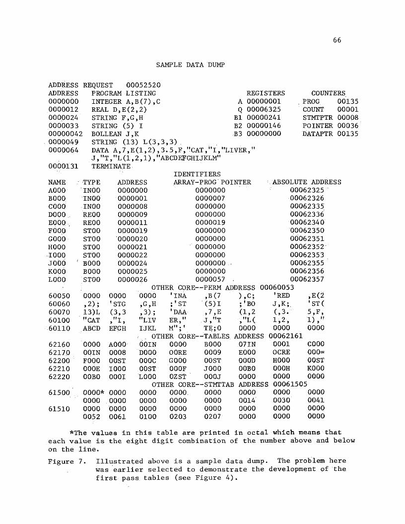
66
SAMPLE DATA DUMP
ADDRESS REQUEST 00052520ADDRESS PROGRAM LISTING REGISTERS COUNTERS0000000 INTEGER A,B(7),C A 00000001 . PROG 001350000012 REAL D,E(2,2) Q 00006325 COUNT 000010000024 STRING F,G,H B1 00000241 STMTPTR 000080000033 STRING (5) I B2 00000146 POINTER 0003600000042 BOLLEAN J,K B3 00000000 DATAPTR 00135
, 0000049 STRING (13) L(3,3,3) .0000064 DATA A,7,E(1,2),3.5,F,VCAT,"I,"LIVER,"
J ,"T,"L(1,2,1),"ABCDEFGHIJKLM"0000131 TERMINATE
IDENTIFIERSNAME TYPE ADDRESS ARRAY -PROG'POINTER ABSOLUTE ADDRESSA000 INOO 0000000 0000000 00062325B000 INOO 0000001 0000007 00062326C000 INOO 0000008 0000000 00062335D000 REOO 0000009 0000000 00062336E000 . REOO 0000011 0000019 00062340F000 STOO 0000019 0000000 00062350G000 STOO 0000020 0000000 00062351H000 STOO 0000021 0000000 000623521000 STOO 0000022 0000000 00062353J000 '' B000 0000024 0000000 . 00062355K000 B000 0000025 0000000 00062356L000 STOO 0000026 0000057 ■ 00062357
OTHER CORE;— PERM ADDRESS 0006005360050 0000 0000 0000 ’ INA ,B(7 ),C; ’RED ,E(260060 >2); tSTG ,G,H ;' ST (5)1 ; ’BO J,K; ’ST(60070 13)L (3,3 ,3); ’ DAA »7 ,E (1,2 (,3. 5,F ,60100 "CAT "I » ■*- » "LIV ER," J ,"T V 'U 1,2, 1),"60110 ABCD EFGH IJKL M";T TE; 0 0000 0000 0000
. OTHER CORE— TABLES ADDRESS 0006216162160 0000 AO 00 00IN 0000 B000 07IN 0001 COOO62170 00IN 0008 D000 OORE 0009 E000 OCRE 000-62200 F000 OOST OOOC G000 OOST 000D H000 OOST62210 000E 1000 OOST 000F J000 00B0 000H K00062220 00B0 0001 L000 OZST 000J 0000 0000 0000
OTHER CORE— STMTTABi ADDRESS 0006150561500 0000* 0000 0000 0000 0000 0000 0000 0000
0000 0000 0000 0000 0000 0014 0030 004161510 0000 0000 0000 0000 0000 0000 0000 0000
0052 0061 0100 0203 0207 0000 0000 0000
*The values in this table are printed in octal which means that each value is the eight digit combination of the number above and below on the line.Figure 7. Illustrated above is a sample data dump. The problem here
was earlier selected to demonstrate the development of the first pass tables (see Figure 4).
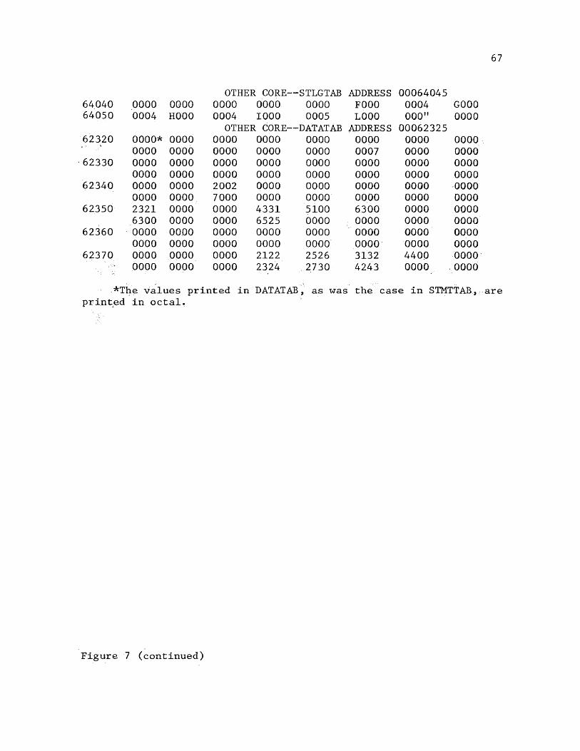
67
OTHER CORE--STLGTAB ADDRESS 0006404564040 0000 0000 0000 0000 0000 F000 0004 GOOO64050 0004 H000 0004 1000 0005 L000 000" 0000
OTHER CORE--DATATAB ADDRESS 0006232562320 0000* 0000 0000 0000 0000 0000 0000 0000
0000 0000 0000 0000 0000 0007 0000 000062330 0000 0000 0000 0000 0000 0000 0000 0000
0000 0000 0000 0000 0000 0000 0000 000062340 0000 0000 2002 0000 0000 0000 0000 0000
0000 0000 7000 0000 0000 0000 0000 000062350 2321 0000 0000 4331 5100 6300 0000 0000
6300 0000 0000 6525 0000 0000 0000 000062360 0000 0000 0000 0000 0000 0000 0000 0000
0000 0000 0000 0000 0000 0000 0000 000062370 0000 0000 0000 2122 2526 3132 4400 0000
0000 0000 0000 2324 2730 4243 0000 0000
*The values printed in DATATAB, as was the case in STMTTAB, are printed in octal.
Figure 7 (continued)

68
shown with the instruction corresponds to the PERM location of the
statement and not to the printed character location of the statement.
Recall that the program is not stored exactly as it is read (see
Section IIA, para 1). The purpose here is that the Interpreter uses the character address as a guide to each statement; so the address
is for the use and benefit of the Interpreter and not the user.
To the right of the program listing is a summary table which
lists the values, at the time of print, of significant registers and
program counters. The CDC 3100 computer has five registers which are
displayed on the computer console. These registers are key to
the programming effort because they are used for all computer operations.
The dump will print a list of these registers, A, Q, Bl, B2, and B3, and their current values. Beside these registers will be a list of
the counters to the more important tables of the Interpreter. These
counters keep a check on PERM which houses the user’s input program,
INST, which contains the last instruction read by the Interpreter,
STMTTAB, which holds the character addresses of each instruction,
TABLES, which is the table for declared variables and statement
numbers,.and DATATAB, which of course is the data tables for each declared variable. The counters which prevent any of these tables from being overloaded are PROG, COUNT, STMTPTR, POINTER, and DATAPTR,
respectively. Periodically, throughout execution of the Interpreter,
checks are made to ensure that these counters, hence the user's
program, are not becoming too large. The routine which makes these
checks is CNTRCKS (Counter Checks); these checks will be discussed in
more detail in Section IV, para 1.

69
After the program has been listed, the Interpreter prints
a table of the statement numbers and declared variables, or as the reader might guess, the information contained in TABLES. The name is
listed first; that is, the variable name or statement number; then
the data type, the relative location of the variable in DATATAB or
the statement number in PERM, whichever is applicable, followed by '
the array prog pointer, which points to the location in PERM where array
dimensioning information for the declared variable can be found, if
applicable, and finally, the absolute address of the variable’s
storage location is printed. • Since the data dump will print DATATAB
in an octal dump with octal core addresses, the user will need the
absolute address in order to locate the value of his variable. All
of the information listed in this table can be found in TABLES .except
the absolute address of the variable, but this information can
easily be determined from the information contained in TABLES.
After the TABLES listing, the Interpreter prints the contents
of the previously mentioned key tables of the Interpreter, These tables which are dumped are PERM, TABLES, STMTTAB, DATATAB, and
STLGTAB, each of which should be of interest to the user. PERM, TABLES,
STMTTAB, and DATATAB have already been pointed to above for their
importance, but the other one was not mentioned. STLGTAB, as may be
recalled (see Section IIA, para 2), is the source of the declared
length of the string variables, and is used to assist the Interpreter
in proper storage-of string variables. Of the five tables dumped,
PERM, TABLES, and STLGTAB, all of which contain mostly BCD characters
70
are dumped in BCD rather than octal. The remaining two tables are
dumped in octal.
Before each table, a message will be printed to indicate which
table is to follow, and the absolute core location of where it begins.
Following, of course, is the table dump. The Interpreter is not
responsible for the octal core dump. It makes use of the ECDAPS
routine, SNAPSHOT (see Section IC, para 4), which handles the output
request. When the dump is completed, the Interpreter has finished
execution of the user's program, and returns control to the CDC 3100
system.■
> To be mentioned is the criteria for the data dump. Naturally,
the user will not always want to see the full data dump; on the other
hand, there will be special times when the user will want it. The
Interpreter has tried to second guess the user in this area by providing
the capability to get a dump at several strategic evolutions of the execution cycle, but the dump is actually provided by the user's
intervention. The user is given the capability to tell the Interpreter the circumstances in which the dump will be needed and the Interpreter responds to the needs of the user. The user is able to communicate his
desires to the Interpreter through the use of jump switches which are
a part of the CDC 3100. The turning on of a jump switch will cause the
Interpreter to deviate from its normal course, and honor the user's
request. The jump switches and their function are as follows:
1. .SJ1— Jump switch 1 causes a complete data dump at thenormal termination of the user's program. This dump is particularly
71
valuable when the user has a problem getting the correct output,
even though the Interpreter has given no diagnostics.
2. SJ2— Jump switch 2 causes the emergency abort of the user’s
program in the event of an infinite loop. Also, jump switch 2 allows
the user to abort the program listing which follows the execution
cycle. The latter option should not be put into effect until the
listing actually begins to prevent accidentally aborting the program.
3. SJ5— Jump switch 5 will cause a dump if the Interpreter
finds a diagnostic error. After the dump, though, the Interpreter
will terminate the program execution. More about diagnostic errors
will be discussed in Section IV.
4. SJ6— Jump switch 6 -causes a dump of the program and files after the first pass. This dump will allow the user to check the
tables which were developed in the first pass (see Figure 4) and
continue with the program execution. This option does not cause the
automatic abort of the user's program.
The reader will note that the Interpreter makes use of only
four of the six jump switches. Jump switch 3 has a special function
for the ECDAPS system which would be pertinent when using the ECDAPS
routines. Jump switch 4 is being reserved for later technology of
the Interpreter if such technology is possible (see Section V for a
discussion of the ideas for future consideration for the Interpreter).
In the discussion above, it was mentioned that a program
listing follows the execution of the program. If the user does not
use any of the jump switch options provided, then the Interpreter
72
will follow the program output with a listing of the program. In
nearly every instance, the user will'want such a listing. In those
rare cases when the user feels the program is too lengthy for the
complete listing, he may abort the listing using jump switch 2 as
prescribed above.
The data dump routine is rather simple in style, but it is
very important to the user when he has a software problem. Therefore,
the Interpreter has tried.to provide, above all other features, an
adequate data dump facility. Another important feature for the user
when he has a problem is clear and precise diagnostics. Discussion
of the diagnostic system will follow in Section IV.
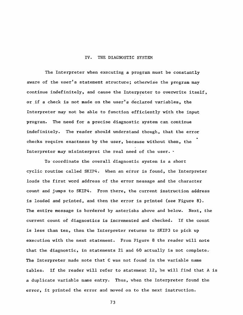
IV. THE DIAGNOSTIC SYSTEM
The Interpreter when executing a program must be constantly
aware of the user’s statement structure; otherwise the program may
continue indefinitely, and cause the Interpreter to overwrite itself,
or if a check is not made on the user's declared variables, the
Interpreter may not be able to function efficiently with the input
program. The need for a precise diagnostic system can continue
indefinitely. The reader should understand though, that the error
checks require exactness by the user, because without them, the
Interpreter may misinterpret the real need of the user. ~
To coordinate the overall diagnostic system is a short
cyclic routine called SKIP4. When an error is found, the Interpreter
loads the first word address of the error message and the character
count and jumps to SKIP4. From there, the current instruction address
is loaded and printed, and then the error is printed (see Figure 8).
The entire message is bordered by asterisks above and below. Next, the
current count of diagnostics is incremented and checked. If the count
is less than ten, then the Interpreter returns to SKIPS to pick up
execution with the next statement. From Figure 8 the reader will note
that the diagnostic, in statements 21 and 60 actually is not complete.
The Interpreter made note that C was not found in the variable name
tables. If the reader will refer to statement 12, he will find that A is
a duplicate variable name entry. Thus, when the Interpreter found the
error, it printed the error and moved on to the next instruction.
73
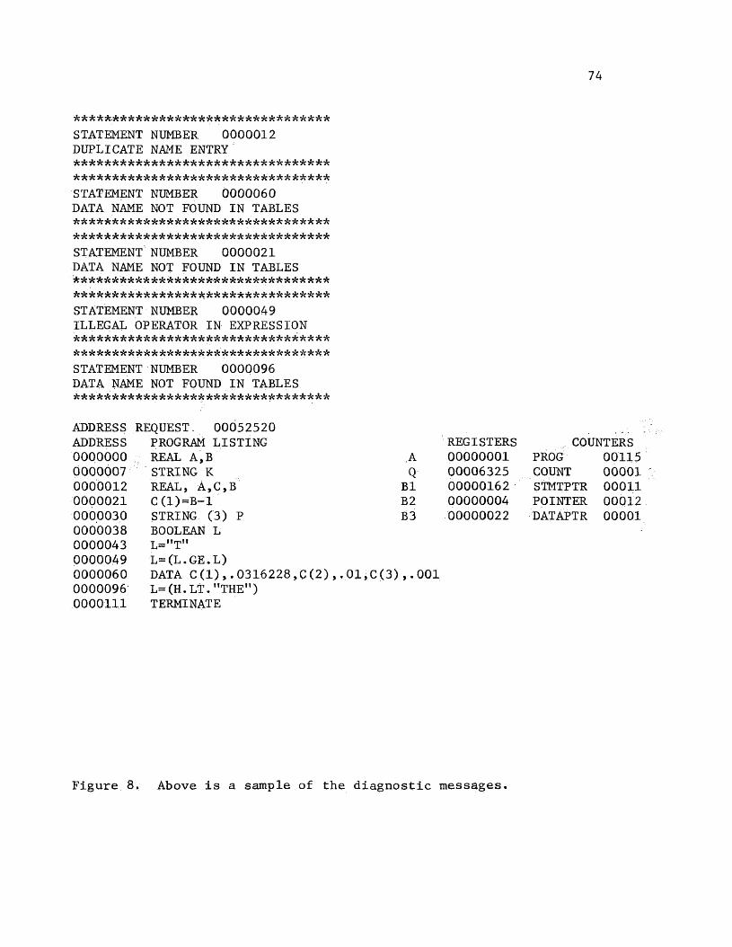
74
*****-**************** ************ STATEMENT NUMBER 0000012 DUPLICATE NAME ENTRY ********************************* ********************************* STATEMENT NUMBER 0000060 DATA NAME NOT FOUND IN TABLES ********************************* ********************************* STATEMENT NUMBER 0000021 DATA NAME NOT FOUND IN TABLES * * * * * * * * * * * * * * * * * * * * * * * * * * * * * * * * ** * * * * * * * * * * * * * * * * * * * * * * * * * * * * * * * * STATEMENT NUMBER 0000049 ILLEGAL OPERATOR IN EXPRESSION ********************************* ********************************* STATEMENT NUMBER 0000096 DATA NAME NOT FOUND IN TABLES * * * * * * * * * * * * * * * * * * * * * * * * * * * * * * * * *
ADDRESS REQUEST. 00052520ADDRESS PROGRAM LISTING REGISTERS COUNTERS0000000 REAL A,B A 00000001 PROG 001150000007 STRING K Q 00006325 COUNT 000010000012 REAL, A,C,B B1 00000162 STMTPTR 000110000021 C (l)-B-l B2 00000004 POINTER 000120000030 STRING (3) P B3 00000022 DATAPTR 000010000038 BOOLEAN L0000043 L="T"0000049 L=(L.GE.L)0000060 DATA C(l),.0316228,0(2) ,.01,C(3),.0010000096 L= (H. LT. ’’THE")0000111 TERMINATE
Figure 8. Above is a sample of the diagnostic messages.
75
The variable C was never declared to the Interpreter because the
statement had been aborted due to the duplicate variable name error.
Once statement 12 is corrected, another execution will result in an
error in statements 21 and 60 which says that an array has been used
but has not been declared. The reader might question the Interpreter’s
needing two separate executions to discover all the errors in the
user’s program. The Interpreter cannot uncover every error because
if the Interpreter returned to the same line after printing the
diagnostic message instead of moving to the next instruction, it may
lose system control when it tries to pick up execution of the statement.
It should be noted that the Interpreter discovers all errors while
trying to execute the instruction, but when an error is found, the
Interpreter, no longer attempts to execute the statement. There is-no
presearch to check for errors. Another example of the same situation
can be found in Statement 96. In the first execution attempt, the
Interpreter printed that H could not be found in the variable name .
table because it had not been declared. When the user declares the
Variable, the next execution attempt will site the same instruction
for an illegal operator; that is, the LT operator is not valid for
string variables (see Section IIB, para la3).From the above discussion, the reader can see that the
Interpreter may require several execution attempts before the bugs will
be completely removed. To assist the user in understanding the
diagnostic messages which are printed, each message will be discussed.

76
1. "COUNTER ERROR AT XXXX"— This error appears when the user
has exceeded the input storage restrictions. The five counters which appear in the right corner of the data dump— PROG, COUNT, STMTPTR,
DATAPTR, and POINTER-— are the measures of core used by the user's
program. The limits assigned to each of these counters are as follows:(a) PROG— -PROG counts the number of characters in the user’s
permanent program and is restricted to 4000 (decimal) characters which '
will normally figure to be a 500 instruction program.
(b) COUNT— COUNT counts the number, of characters read into the
current instruction and its limit is 160 decimal characters. The main
reason for the extreme length allowance is to handle the variable
length of the string variables. The reader might recall that a
string variable is limited to a length of 150 characters.
(c) STMTPTR-STMTPTR counts the number of instructions.:
Its actual purpose is to point to the table which contains the
statement character addresses, STMTTAB. The limit for this counter ! - ;
is 500 which will assume, as does PROG, that the average instruction
.length will be 8 characters.(d) DATAPTR— :DATAPTR points to the data tables, DATATAB. The
limit of data values is set to 1000 words. The data tables are mixed
up with integers, floating point numbers, and variable length string
characters, all of which require a different number of words in
core; thus, it is nearly impossible to estimate how far this limitation
will extend. With 1000 words of core, though, the user should have
enough storage to handle most problems.

77
(e) POINTER— POINTER counts the number of declared variables
and statement numbers. As the reader will recall from Section IIA,
para 2, the Interpreter uses TABLES to store All variable names and
statement numbers; thus, POINTER prevents TABLES from being overflowed.
The limit of variable identifiers is fifty.
After the counter error is printed, the address of the error
location within the Interpreter will be printed. Thus, the user,
if he understands COMPASS, may wish to examine the Interpreter.
If not,.the user can use the current statement number printed above
the error to trace his error.
2. "INSTRUCTION FORMAT ERROR IN STATEMENT NUMBER XXXXXXX"—
As discussed in Section IIA, para 1, DETRMN is a routine used to
locate the instruction type which has been used. If the routine
cannot determine the instruction used, it will print this error.
3. "ARRAY HAS TOO MANY DIMENSIONS"— An array because of
storage limitations must be limited to only six fields. The limit
although small is not unreasonable, because few arrays extend any
deeper.4. "END OF NAME NOT FOUND'— VARIABLE LENGTH ERROR"— The
Interpreter limits the length of variable names to four characters.In the execution of the routine, TABSCAN, when the Interpreter is
searching the variable name and statement number table, if the
variable name which it is searching for is found to be too long, this
error will occur.5. "DATA NAME NOT FOUND IN TABLES"— This'diagnostic indicates
that the user has not declared one of the variable names or statement

78
numbers properly. The user should review his declaration statements
and his statement numbers to resolve this problem.
6. "LAST CARD NOT TERMINATE"— This error can be fatal to the
Interpreter if not remedied. When this error occurs, the Interpreter
prints the message of the console typewriter instead of the printer,
and aborts the program.
7. "ARRAY USED— NOT DECLARED"— Earlier in this section,
mention was made of the variable ’Cf (see Figure 4) which had been
used as an array but not declared in the standard array format.
With that error, this is the message to the user.
8. "ARRAY DECLARED— NOT USED"— -The converse to the previous
error is the case when the user has declared the array, but tried to
use the array as a simple variable. In either situation, the
Interpreter becomes confused by the statement and must abort the
instruction by one of the above two messages.
9. "EXPRESSION TOO LONG"— In any case where the Interpreter
deals with expressions, this error may occur. The purpose of this
diagnostic is not just to restrict the user, but primarily to
return control to the Interpreter when the user has failed to place
a delimiter on his statement. The restrictions imposed by this
diagnostic are:(a) In the FILE Statement, the "limit on the number of
column parameters is eight. Similarly, the time input for this
statement is eight digits for the date time group, MODAHRMN. If
either restriction is violated, this message is printed.
(b) In the MAT Statement, a check is made to guarantee that
the user has not tried to format too many spaces for data items. For
real numbers, the maximum format is F15.7; for integers, it is 17;
and for characters, it is C150. In addition, the statement is
limited to only ten variable names by this diagnostic.
(c) In a Boolean expression, the expression is limited to
twelve characters on each side of the operator.
10. "NAME TOO LONG"— This error is very similar to the
preceding diagnostic. Whenever this message appears, the user should
first look for any variable name which' exceeds four characters in
length; If that is not the error, some other instances where this
message may appear are:
(a) In the FILE Statement, the allowable length for a
station identifier is eight digits.(b) In the GOTO Statement,1 the Interpreter ensures that
the statement number does not exceed three digits (see Section
IIA, para 2) .
(c) In the MAT Statement, the maximum length which can
be formatted is 150 for a lengthy character string.11. "UNMATCHED PARENTHESES"— The Interpreter must*demand
precise notation from the user when dealing with numerical expressions.
Otherwise, if the user is slack in setting up his equation, the
Interpreter will not be able to ensure that it has evaluated the
expression as the user had intended.
12. "NO END PAREN ON NAME"— This error is used to relate to
the user that he has not placed an end parenthesis on the array used
on the left side of the expression.
80
13. "ILLEGAL EXPRESSION IN PARENTHESIS"— This error is
obvious. Some of its uses are!
(a) In specifying the length of string variables in the
STRING Statement, if the input is not numeric, then this error
will result.
(b) In three of the functions, FACT, LN, and SQRT, the
operand must be positive. If they are not, then this error is
indicated.- 14. "SIMPLE VARIABLE NOT DECLARED"— The Interpreter prints
this message if the user has tried to use an array in the operand
of his function. •»;. I
'v, v 15. "ILLEGAL TRIG EXPRESSION"— This error occurs when
the Interpreter finds that COS X=0 when calculating TAN X. This
error is also a divide fault, but the message printed is more precis
L 16. "TOO MANY SIMULTANEOUS LOOPS"— The Interpreter allows
only six nested loops at one time. The total is derived from the
number of FOR Statements used at the same time. ;17. "ITERATION VARIABLE MUST BE AN INTEGER"— In the FOR
Statement, the iteration variable must be an integer and can only
be incremented by integer values.
: 18. "ERROR IN LOOP LIMIT"— In the FOR Statement, the
iteration variable cannot decrement to a negative number. It may .
only increment by one to a positive integer value. Likewise, if
the initial value of the loop counter is greater than the limit
declared in the FOR Statement, then this error message will apply.
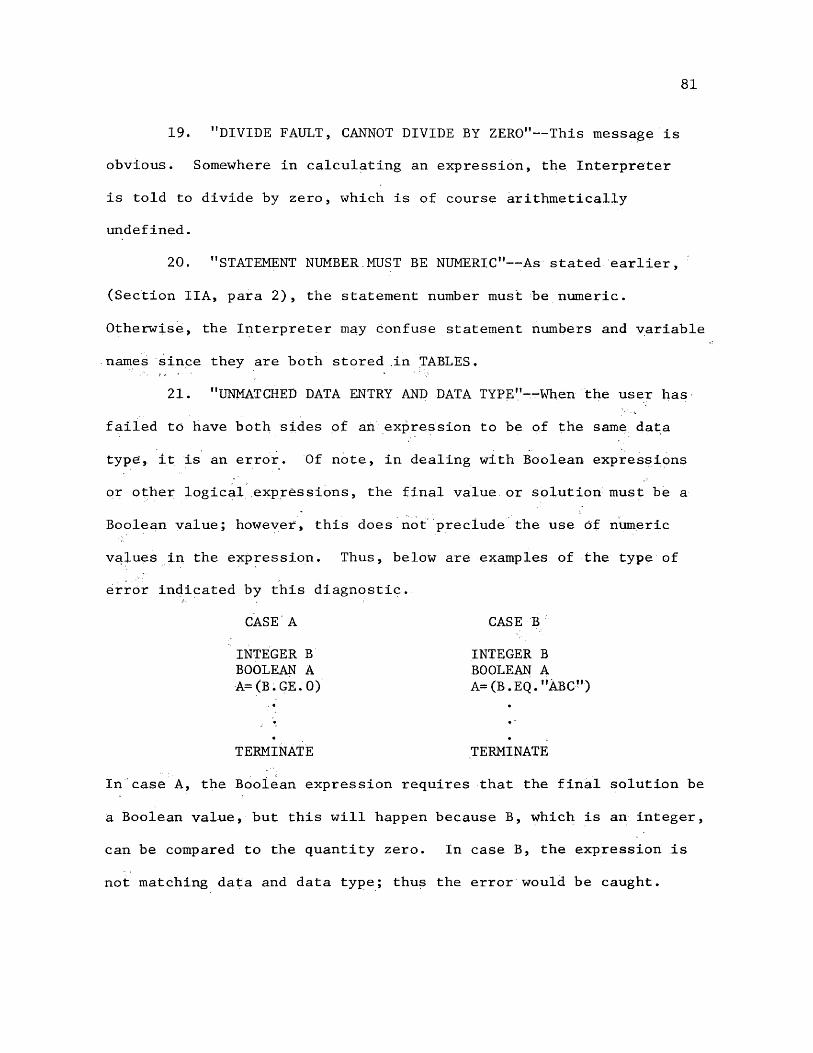
81
19. "DIVIDE FAULT, CANNOT DIVIDE BY ZERO"— This message is obvious. Somewhere in calculating an expression, the Interpreter
is told to divide by zero, which is of course arithmetically undefined.
20. "STATEMENT NUMBER.MUST BE NUMERIC"— As stated earlier, :
(Section IIA, para 2), the statement number must be numeric.
Otherwise, the Interpreter may confuse statement numbers and variable
names since they are both stored .in TABLES.
21. "UNMATCHED DATA ENTRY AND DATA TYPE"— When the user has
failed to have both sides of an expression to be of the same data
type, it is an error. Of note, in dealing with Boolean expressions
or other logical expressions, the final value or solution must be a
Boolean value; however, this does not preclude the use of numeric
values in the expression. Thus, below are examples of the type of
error indicated by this diagnostic.CASE A CASE B
INTEGER B INTEGER BBOOLEAN A BOOLEAN AA=(B.GE.0) A=(B.EQ."ABC")
• • "
• •
TERMINATE TERMINATE
In case A, the Boolean expression requires that the final solution be
a Boolean value, but this will happen because B, which is an integer,
can be compared to the quantity zero. In case B, the expression is
not matching data and data type; thus the error would be caught.
22. "ILLEGAL VARIABLE IN EXPRESSION"— The message of this
diagnostic is the best words for the type of error. Mostly the
diagnostic is to ensure that the user has not tried to incorrectly
use Boolean variable names in normal expression.
23. "DUPLICATE NAME ENTRY"— The message here is equally
obvious. A variable should always be declared once, but it should
never be declared more than once; thus, when the interpreter finds
the same variable declared in more than one place, it prints the
error. • V.-"
24. "ILLEGAL OPERATOR IN EXPRESSION"— This diagnostic
occurs when the user has incorrectly, tried to use an invalid operator
in Boolean and character string expressions. In these two cases,
the only operators allowed are EQ'and NE (see Section IIB, para la3).
In another situation, that of the FILE Statement parameter list, this
error can be found. The Interpreter must be able.to read the data:
parameter request of the statement, or it is an error. If the list
has for some reason been misproported, the error will occur.25. "ERROR IN FORMATTED OUTPUT"— This error is designed to
catch the Interpreter if the MAT Statement has been improperly
constructed. Without such a means to regain control, the Interpreter
could easily write out core. The type of error which this refers
to is when the proper delimiter has been omitted. The Interpreter,
in this case, could continue to write until it had overwritten all
core.26. "EXPRESSION IN WHILE STATEMENT DOES NOT CONVERGE"— The
WHILE Statement is probably the most vulnerable in the Interpreter.
83
If the user fails to properly converge the variable in the expression /
to the limit, the Interpreter may become locked in the loop. To overcome this problem, the Interpreter makes use of the computer's
internal clock to check the duration of the statement. If the time
of execution of the loop exceeds the limit set (about 10 seconds),,
the Interpreter will print this error and move on. Of note, the
Interpreter does not abort the program until ten diagnostics have
occurred, so the message will actually be printed ten times in most
cases. The advantage here is that the Interpreter will continue to
print the next ten solutions so that the user may actually observe the
divergence of his variable.
. H 27. "INVALID WHILE L00PM-“Td terminate the WHILE; Statement, . ~U! '
the user must close the loop with a BACK Statement, or the WHILE loop ’ :
is invalid, and the message will be printed. ; ’Now the user and reader have completed the investigation
of the Interpreter both in theory and in operation. In every
instance, thought has been directed toward the needs of the user. V
However, even as the Interpreter nears completion, there are several closing thoughts which must be entered as possible improvements for
the system. These ideas will be discussed in the following and
final section.
V. CLOSING COMMENTS
When thoughts first began to develop the Interpreter for the
CDC 3100 Computer, they were somewhat vague and unsophisticated. As
a result, much of the finished Interpreter is vague and unsophisticated.
The original idea was to develop a language which could utilize features
of other popular higher level languages, but as the program began to
unfold, new requests began to surface. The Interpreter began as a
small system primarily for my personal programming needs with the
staff1s computer, but soon, others became interested in the planned
capabilities for the system. High among everyone’s prierities was
a FORTRAN Interpreter because many of the staff’s analysts have massive
FORTRAN programs which can be adapted to the CDC system.
The first attempt at the Interpreter does not have the
FORTRAN Interpreter, but some effort has been made to lay the
groundwork for the change. Essentially, the only modification
required is to change some instruction names and to perhaps add some
new instructions. It was decided not to move into the FORTRAN
version of the Interpreter with this present system because of the
following reasons:
1. By the nature of the staff’s request and the already
mentioned core limitation on the Interpreter, a massive FORTRAN
program cannot be executed in 12K words of core.
84
85
.2. A major concept in FORTRAN programming which has not
been dealt with in the first version of the Interpreter, also
because of core, is subroutine programming. The reader will probably
note that subroutines are designed to save core; however the mechanics
of simulating the FORTRAN subroutine will entail lengthy software.
It would be nearly pointless to strike out in the direction.of
subroutines too soon if the results were less than desirable. It is
hoped that the opportunity will later arise to update the current
Interpreter with the subroutine capability.3. The entire FORTRAN instruction set is quite massive,'
and'the expected effort for the original Interpreter was to be
just a few months. My military tour at the command ends in a
short while, and I had hoped to leave at least the current higher
level language programming capability for the staff.
As time permits toward the end of my military tour, I hope
to fulfill the expectation of a FORTRAN Interpreter in the following
ways:
1. The most severe deterrent to the addition of the
FORTRAN Interpreter is, as was cited above, core. From Section IV,
the reader knows that the length of the user’s program is limited
to 500 instructions (see Section IV, para lc). Surely most lengthy
FORTRAN programs will exceed the instruction limit. In addition,
the size of the data tables is limited to 1000 words of core. These
limitations simply are not realistic for a user’s program, and they must be greatly increased if the Interpreter is to be of value. The
86
update to the Interpreter will shift program and data storage to
tapes. This modification alone will unlock core to allow the r
Interpreter to tackle any and all programs. The use of a tape for.
program storage and another tape for data files will remove the user
from the ridiculous restrictions which must be imposed on the 12K
Interpreter.
2. The reader will recall that the Interpreter uses the
first two characters to identify the type of instruction in a
statement. The'routine PREPROC actually uses a table to compare the
instruction name entered by the user with the instruction name
recognized by the Interpreter. When a match is found-the routine rewrites the instruction using the corresponding two'character codes
for the instruction. If the table used for the comparisons had a new set of instruction names, and the:user changed his instruction set
accordingly, then the instruction names have been changed.' For example':.,
in the current instruction set, the user must use the command CARD to
cause the Interpreter to read a card. If the name in the table were
changed to READ, the user would be required to use READ to have his
card read. Of note, the instruction in PERM would still be stored
with the same two digit code CA for CARD, but to the user, the instruction READ would be executed.1 The above procedure will be
implemented to modify the current instruction set to match the
FORTRAN instruction set. Of course the instruction set which now
exists with the Interpreter is only a small part of the set which
will be required for FORTRAN. Thus conversion will require not only

87
changing the names of many of the current instructions, but also the
. addition of many new routines.
3. As. was noted above, the addition of subroutine capability
, will be a high priority for the upcoming changes..
4. In the I/O Statements, the instructions do not provide
for .the-implied loop that is, the user cannot express the variable
operand as an array with the indice being an automatically
incrementing variable. At the' present time» the user must either loop
through the statement until he has covered the desired elements, or he must repeat each element in the, I/O instruction. In the update,
this implied loop is a planned addition. .
5. In Section III, the reader might recall that the Interpreter
had reserved jump switch 4 for * a special purpose. Now that purpose
can be revealed. As programs are written for the Interpreter,; a dual
, requirement will develop for a FORTRAN Interpreter and the special
language Interpreter. .Therefore, by use of the jump switch 4, the
user: can have a choice of the Interpreter he pref ers. s iV ;
, ‘ With the final changes as outlined above, the Interpreter
will be finished, unless of course, more needs occur. At that time,
the user should have unlimited program and data storage areas, and he
should have FORTRAN as well as the Interpreter’s language with which
to work.

APPENDIX A
THE MAT STATEMENT IN USE;
In Section IIB, para lb, the Interpreter deals with the
Input/Output Instructions, both formatted and unformatted. The
illustration presented here should indicate the advantage in the MAT Statement. In Figures 9 and 10, the user will observe the
same problem in four different output situations. ,
In Figure 9, the output is handled using the MAT Statement.
In the listing., the solution is obviously easier to read because the
numbers are not sloppily printed with leading and trailing zeroes.
The printout of the real array has some extra zeroes; however,
they are there by request from the MAT instruction in line 87.
The MAT Statement has ordered four real numbers to be printed,
each with field length seven including two digits to the tight of
the decimal.
In Figure.10, the printouts are not organized by the MAT Statement, so the format designed by the Interpreter, as the default
case, must be used. The user will note how unorderly these listings
are, particularly in the real array case. Without a doubt, the
MAT Statements enable clearer and easier to read output.
88
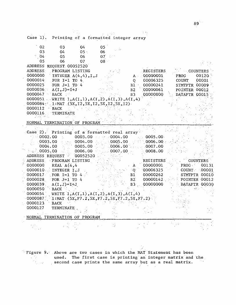
89
Case 1) . Printing of a formatted integer array
02 03 04 0503 04 05 06
; , 04 05 06 07 :05 06 07 08
ADDRESS REQUEST, 00052520ADDRESS PROGRAM LISTING REGISTERS .7 COUNTERS0000000 ' INTEGER A(4,4),I,J A 00000001 PROG 001200000014 FOR 1=1 TO 4 Q 00006325 COUNT 000010000025 FOR J=1 TO 4 B1 • 00000241 STMTPTR 000090000036 A(I,J)=I+J B2 .00000061 POINTER 000120000047 BACK : ' 7'"’' B3 oooooooo ;■ DATAPTR 000150000051 WRITE 1,A(1,1) »A(I , 2 ) , A (1 ,3 ) , A (1,4 ) V.-*'
0000084 ;: 1:MAT (5X,I2,5X,I2,5X,I2,5X,.I2) 0000112 BACK V - : ; A ' ■ ^ -0000116 TERMINATE ‘ 7 V ANORMAL TERMINATION OF PROGRAM
Case 2). Printing; of a formatted real array '■■7"r"7, ' 7'-.-,7.;' 70002.00 : 0003.00 0004.00 0005.000003.00 0004.00 / 0005.00 0006.00 •V.is.' * ■ * , 70004.00 : 0005.00 7 7 0006.00 7 0007.00
• , 0005.00 0006.00 7 0007.00 0008.00ADDRESS REQUEST 7 00052520ADDRESS PROGRAM LISTING REGISTERS . COUNTERS0000000 REAL A (4 ,4 ;:';7 . A 00000001 > PROG i r 001310000010 INTEGER I,J - r■V q 00006325 COUNT: 900010000017 FOR 1=1 TO 4 B1 00000262 • STMTPTR 000100000028 FOR J=1 TO 4 7 / :7.7,;.'- B2 00000142 , 7 7. POINTER 000120000039 A(I,J)=I+J 7 7- B3 oooooooo V DATAPTR 000300000050 BACK ' . 'i ■ • . *7- •0000054 WRITE 1,A(I,1),A(I,2) ,A(1 ,3) , A(1,4)0000087.. 1 :MAT (5X,F7.2,5X,F7.2,5X,F7 . 2 ,5X,F772) '0000123 1 BACK0000127 TERMINATE ; NORMAL TERMINATION OF PROGRAM
Figure 9. Above are two cases in which the MAT Statement has beenused. The first case is printing an integer matrix and the
- second case prints the same array but as a real matrix.
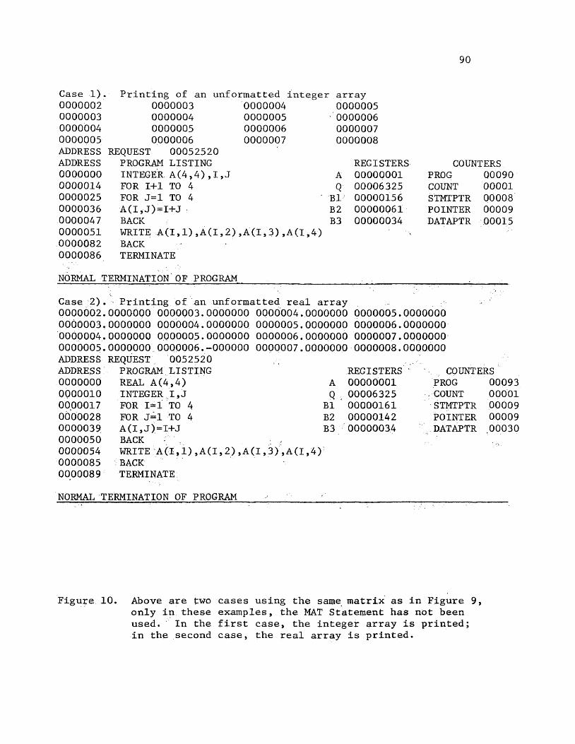
90
Case 1). Printing of an unformatted integer array0000002 0000003 0000004 00000050000003 0000004 0000005 00000060000004 0000005 0000006 00000070000005 0000006 0000007 0000008ADDRESS REQUEST 00052520ADDRESS PROGRAM LISTING REGISTERS COUNTERS0000000 INTEGER A (4,4),I ,J A 00000001 PROG 000900000014 FOR 1+1 TO 4 Q 00006325 COUNT 000010000025 FOR J=1 TO 4 B1 00000156 STMTPTR 000080000036 A(I,J)=I+J ; B2 00000061 POINTER 000090000047 BACK B3 00000034 DATAPTR 000150000051 WRITE A(I»1),A(I,2) ,A(I,3),A(I,4) '00000820000086
BACKTERMINATE
NORMAL TERMINATION OF PROGRAM
Case 2). Printing of an unformatted real array0000002.0000000 0000003.0000000 0000004.0000000 0000005.00000000000003.0000000 0000004.0000000 0000005.0000000 0000006.00000000000004.0000000 0000005.0000000 0000006.0000000 0000007.00000000000005.0000000 0000006.-000000 0000007.0000000 0000008.0000000 ADDRESS REQUEST 0052520ADDRESS PROGRAM LISTING0000000 REAL A (4,4) A0000010 INTEGER I,J Q00.00017 FOR 1=1 TO 4 B10000028 FOR J=1 TO 4 B20000039 A(I,J)=I+J B30000050 BACK : .0000054 WRITE A(I,1),A(I,2),A(I,3),A(I,4)0000085 BACK0000089 TERMINATE
REGISTERS0000000100006325000001610000014200000034
COUNTERSPROGCOUNTSTMTPTRPOINTERDATAPTR
0009300001000090000900030
NORMAL TERMINATION OF PROGRAM
Figure 10. Above are two cases using the same matrix as in Figure 9, only in these examples, the MAT Statement has not been used. In the first case, the integer array is printed; in the second case, the real array is printed.
APPENDIX B
FUNCTION ACCURACY
A very significant factor for the Interpreter is just
how well are the functions being calculated. It is definitely
important to have an efficient technique to calculate these values;' .
however, if the values are inaccurate, the user will be in trouble.
Therefore, first emphasis is given to accuracy and second concern to
technique. <4
• ' In the figures which follow, Figures 11 and 12, the reader ‘will observe a series of function evaluations.- - The-calculated values
are printed to the seventh decimal and have been verified to be
accurate to the seventh decimal by a calculator. By being able to
insure calculator accuracy for most calculations, the Interpreter
passes the accuracy test. Although the example programs only evaluate
the E X P L N , SIN; COS, and SQR.T functions, each function of the
Interpreter has undergone independent testing with the same high
results; thus, the Interpreter has licked the problem of providing
dependable solutions. Now, the concern can turn to more efficient
operation.
91

92
1.01005 1.02020 1.03045 1.04081 1.05127 1.06183 1.07250, 1.08328 1.09417 i:10517 ADDRESS ADDRESS 0000000 0000008 0000013 0000017 0000030 0000046 0000058 0000073 0000088 0000103 0000122 0000157 0000163 0000167 0000221
0.00000 0.69314. 1.09861 1.38629 1.60943 1.79175 1.94591 2.07944 2.19722 2.30258
REQUEST ,
,0.17364 . 0.34202 0.49999 0.64278 0.76604 0.86602 0.93969 0. 98480 1.00000 0.98480'
0052520
0.98480 0,93969 0.86602 0.76604 0.64278 0.50000 0.34202 0.17364 0.00000
-0.17364
PROGRAM LISTING REAL A(6)INTEGER I1=1 / ■ . . 1WHILE (I.LE.10)A(1)=EXP (1/100) ;v.A(2)=LN(I) J 'A(3)=SIN(1*10)A(4) = C0S (1*10) r ;A(5)=SQRT(1*10) . 1 •A(6)=(1*10)**(1/2) -WRITE 1,A(l),A(2),A(3),A(4)
• 1=1+1 K-' • vb a c k .a ; . v 71:MAT (F7 .5 ,2X,F7 .5 ,1XSF7.5 TERMINATE :
03.162277604.472135905.477225506.324555307.071067807.745966608.366600208.944271909.486832910.0000000
03.162277604.472135905.4772255 ■061324555307,071067807.745966608.366600208.944271909.486832910.0000000
AQ
B1B2B3
REGISTERS00000001000063250000016100000242OOOOOOOO
COUNTERSPROGCOUNTSTMTPTRPOINTERDATAPTR
0022500001000150000600013
a .: A; '• H 7' 7 , . ?-.* "A ‘
•7 A •,A('5),A(6), ' ■ / j ' ■ ■ - ■/ y
.V • 5, r r ‘ •• ■
;*2X,F7 .5 ,2X?F10. 7 ,2X,F10. 7)
NORMAL TERMINATION OF PROGRAM
Figure 11. Above is a sample program which demonstrates the preciseness ■ of the Interpreter's functions. V 4

93
1000.00000 0989.26786 0978.53572 0967.80358 0957.07144 0946.33930 0935.60716 0924.87502 0914.14288 0903.41074
ADDRESS REQUEST ADDRESS 0000000 000000900000160000030000003900000500000061000009400001070000111
31.622776631.452628831.2815555 '31.109541630.936571230.762628330.587696230.411757930.2347958 30.0567919
0052520 PROGRAM LISTING REAL A, B , I 1=1000WHILE (I.GT.900) A=SQRT(I)B=I**(l/2)WRITE 1,I,A,B 1 :MAT (5X,F10.5,5X,F10 1=1-10.73214 *BACKTERMINATE
31.622776631.452628831.2815555 31.109541630.936571230.762628330.587696230.411757930.2347958
• 30.0567919
REGISTERS A 00000001 Q 00006325
B1 00000126 B2 00000162 B3 OOOOOOOO
7,5X,F10.7)
NORMAL TERMINATION OF PROGRAM
COUNTERS PROG 00115 COUNT 00001 STMTPTR 00010 POINTER 00009 DATAPTR 00006
Figure 12. Above is another example which demonstrates the accuracy of the squareroot function.

APPENDIX C
LOGICAL EXPRESSIONS , >
In addition to performing normal arithmetic calculations, the
Interpreter also provides the capability to evaluate Boolean expressions.
A Boolean expression in its most simple form is the assignment to a '
Boolean variable the value of TRUE or FALSE. As the expression becomes :
more complex, the value is arrived at by comparing two subexpressions,
x and y, where the level of comparison is set by a logical operator.
Por a discussion of logical operators, see Section IIB, paira la'3>
The most sophisticated level of Boolean expression is achieved
by combining the above subexpressions with another set of subexpressions
by a logical conjunction. These conjunctions were discussed in
Section IIB, para 2b. For an illustration of these types of Boolean
expressions in use, see Figure 13. . ”
94
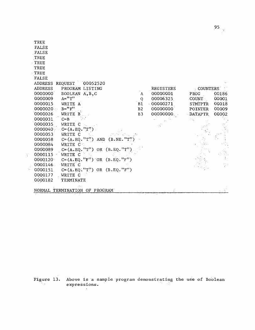
TRUEFALSEFALSETRUETRUETRUETRUEFALSEADDRESS REQUEST 00052520ADDRESS PROGRAM LISTING REGISTERS : COUNTERS ‘ooooooo BOOLEAN A, B ,C A 00000001 PROG 001860000009 A="T" Q 00006325. COUNT 000010000015 WRITE A B1 00000271 STMTPTR 000180000020 B="F" B2 00000000 POINTER 000090000026 WRITE B B3 00000000 DATAPTR 000020000031 C=B '0000035 WRITE C ,0000040 C=(A.EQ."T")0000053 WRITE C0000058 C=(A.EQ."Tm) a n d (b .n e .mT")0000084 WRITE C0000089 C=(A.EQ.MT") OR (B.EQ."T")0000115 ' WRITE C0000120 C=(A.EQ."F") OR (B.EQ."F")0000146 WRITE C0000151 C=(A.EQ."T") OR (B.EQ."F") 0000177 WRITE C 0000182 TERMINATE
NORMAL TERMINATION OF PROGRAM
Figure 13. Above is a sample program demonstrating the use of Boolean expressions.
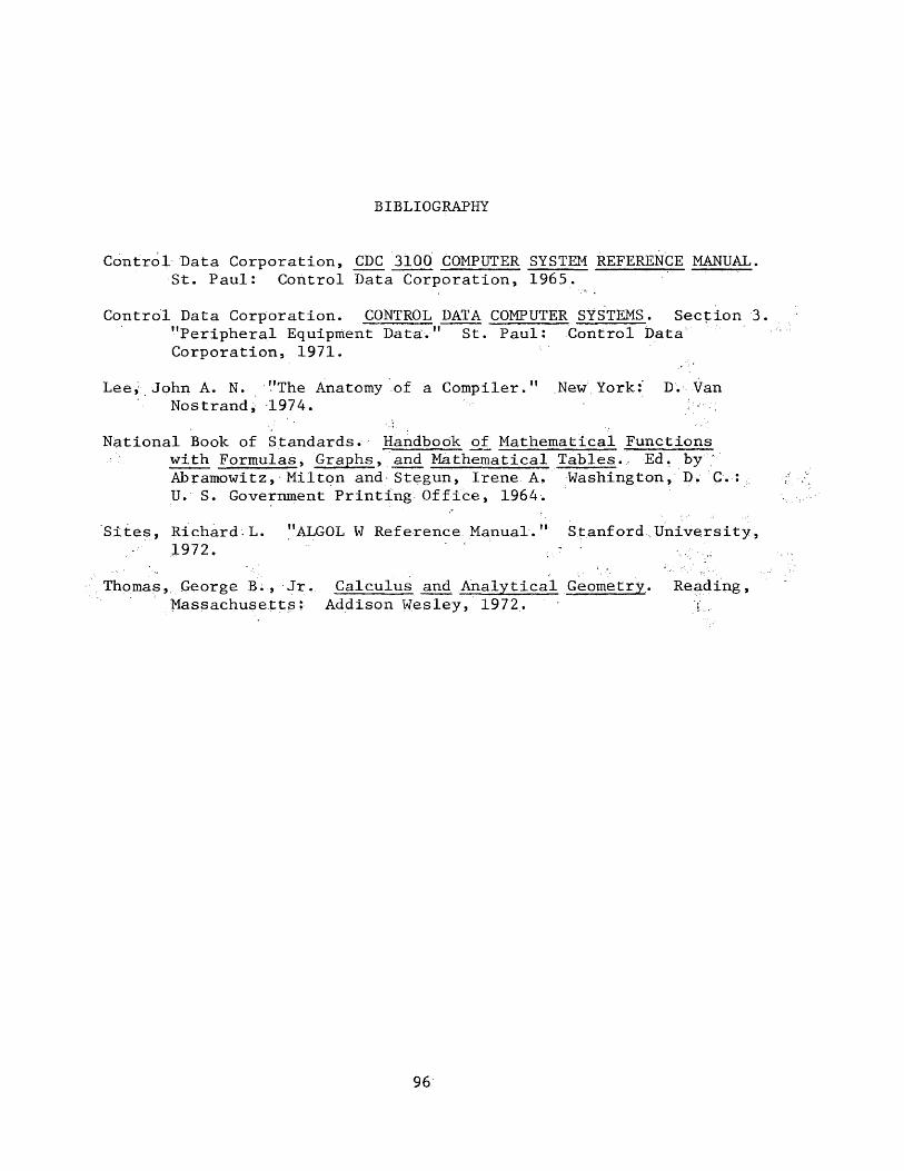
BIBLIOGRAPHY
Control Data Corporation, CPC 3100 COMPUTER SYSTEM REFERENCE MANUAL. St. Paul: Control Data Corporation, 1965.
Control Data Corporation. CONTROL DATA COMPUTER SYSTEMS. Section 3. "Peripheral Equipment Data." St. Paul: Control DataCorporation, 1971.
Lee, John A. N. ’’The Anatomy of a Compiler." New York:" D. Van Nostrand, 1974. :
National Book of Standards. Handbook of Mathematical Functions with Formulas, Graphs, and Mathematical Tables.- Ed. by Abramowitz, Milton and Stegun, Irene A. Washington, D. C.:U. S. Government Printing Office, 1964.
Sites, Richard-L. "ALGOL W Reference. Manual.11 Stanford University, 1972. ‘ ;
Thomas, George B. , Jr. Calculus and Analytical Geometry.. Reading, Massachusetts; Addison Wesley, 1972. i
96

97
VITA
James Thomas Lee, Jr.
Born in Newport News, Virginia, November 28, 1948. Graduated
from Hampton High' School in Hampton, Virginia in ,June 1966, B.A. ,
Old Dominion University, 1972. M.S. candidate, College of William ■
and- Mary, 1973-75, with a concentration in Computer Systems and
Programming. The course requirements for this degree have been
completed, but not. the thesis: Implementation,of a Special Language
Interpreter for the CDC 3100 Computer.
In November 1972, the author .entered the U. S.. Navy, '
graduated from Officer Candidate School, Newport, Rhode Island, and
presently serves as Automated Data. Processing Officer.


![Multi-language Interpreter Services · 2019. 8. 8. · Multi-language Interpreter Services [English] ATTENTION: Language assistance services, free of charge, are available to you.For](https://static.fdocuments.us/doc/165x107/60b30f3ee40b5a04f70a9ff8/multi-language-interpreter-services-2019-8-8-multi-language-interpreter-services.jpg)
