
The Hydraulic Infinite Linear Actuator with Multiple Rods · E-mail: [email protected],...
15
The 15th Scandinavian International Conference on Fluid Power, SICFP’17, June 7-9, 2017, Linköping, Sweden The Hydraulic Infinite Linear Actuator with Multiple Rods Magnus Landberg, Magnus Sethson*, Petter Krus* Saab Aeronautics, Linköping, Sweden E-mail: [email protected], [email protected], [email protected] * Division of Fluid and Mechatronic Systems; Department of Management and Engineering, Linköping University, Linköping, Sweden Abstract Future hydraulic actuation systems can be significantly improved by utilisation of a new type of hydraulic linear actuator technology. By enabling multiple actuating elements, integrated in a compact and lightweight single unit controlled by ordinary directional valves it is possible to achieve a high position accuracy. This is a new way to generate and distribute mechanical linear movement and force by using hydraulic actuators in a cost effective way, in less responsive closed loop systems. This is a variant on the Hydraulic Infinite Linear Actuator, HILA, invention. The technology also represents a new sort of digital hydraulics. The presented technology provides typical hydraulic actuator characteristics with high system pressure and potentially no external oil leakage. It is based on a well-known hydraulic clamping element technology used in a new way, where the piston and the piston rod can quickly be coupled and uncoupled by means of the clamping element in a failsafe way by using well defined incremental steps. HILA in its simplest usage, provides new features to hydraulic cylinders such as providing very long strokes, high rod speed, and small chamber volumes which means high stiffness and low capacitance. The aim of this study is to present a fundamentally new way of using hydraulic actuators. The invention is called the Hydraulic Infinite Linear Actuator with Multiple Rods, HILA MR. The study presents the idea, principles and feasible combinations of the technology. Also applications in the aircraft and robotic field will be presented. Keywords: hydraulic actuator, incremental control, snake-like robot, robot arm 1 Introduction Linear hydraulic actuators is highly competitive, unique in some aspects and have significant advantages compared with electric motor drives and electric actuators. These advantages are higher power to weight ratio, stiffer than electric drives, smoother performance at low speed, wider speed range, and greater extent of self-cooling even in stall condition [1]. In areas where high forces and precise movements are needed, hydraulic solutions are often required. Reducing the size of fluid power components and systems, by increasing power density, while maintaining power output provides a great benefit. There is a need of multiple actuator functions with high requirements for strength and stiffness to be implemented especially in confined working spaces. These are common in the aircraft and automotive production, where also compactness and agility are advantageous. These requirements are also common in robot applications, such as articulated robots and snake-like robots. Additionally, the hydraulic cylinder needs to be designed for longer strokes for use in Cartesian/Gantry robots, tooling machines and additive manufacturing of bigger objects. The basic invention, in this paper, is a hydraulic cylinder with a releasable piston. It is called the Hydraulic Infinite Linear Actuator (HILA) and is presented in [1]. A hydraulic membrane, the clamping mechanism, is connecting the piston and the rod when pressurised. By using simple logic valves for pressurizing, the piston and rod can be connected and disconnected with maximum secure and reliable clamping in a fast way. The paper presents a new way of using hydraulic actuators and reports the present state of the HILA development project, that is a collaborative work between Linköping University and Saab AB. In this paper, the focus will be on finding interesting applications that can further enhance the development process of the project. Hopefully, at the same time, the study of the applications will have commercial impact. The ideas and principles of the multiple rod technology will be presented, mainly on a conceptual level. To some extent this project takes the hydraulic cylinder technology into new exciting areas, as this technology has been developed slowly in recent decades compared to electric linear actuators. The disposition of the article is as follows. It is divided into four main parts, see fig 1. The first part is a description of the basic HILA technology with only one piston rod; the structure and its operation of a standard cylinder. It also describes how bronze bearings and boots can replace the rubber seals between the piston and the cylinder; the advantages and disadvantages, including removing of external leakage, the ability to handle lateral forces and increase the maximum rod speed. In the second part, HILA with incremental control is presented. It adds new features to present hydraulic cylinder technology and can be a potential alternative to expensive electric and hydraulic servo systems, when high position accuracy is the primary goal within less responsive closed loop systems. The technology also represents a new sort of digital hydraulics. An aircraft high lift flap system with trim capability has been chosen as a suitable example for aviation applications. This normally requires expensive, complex and maintenance intensive electrical or hydraulic actuation systems. The presented technology can also be used on the leading edge slat system. Non-reviewed paper. SICFP - June Linköping, Sweden
Transcript of The Hydraulic Infinite Linear Actuator with Multiple Rods · E-mail: [email protected],...

The 15th Scandinavian International Conference on Fluid Power, SICFP’17, June 7-9, 2017, Linköping, Sweden
The Hydraulic Infinite Linear Actuator with Multiple Rods
Magnus Landberg, Magnus Sethson*, Petter Krus*
Saab Aeronautics, Linköping, SwedenE-mail: [email protected], [email protected], [email protected]
* Division of Fluid and Mechatronic Systems;Department of Management and Engineering,
Linköping University, Linköping, Sweden
AbstractFuture hydraulic actuation systems can be significantly improved by utilisation of a new type of hydraulic linear actuator technology.By enabling multiple actuating elements, integrated in a compact and lightweight single unit controlled by ordinary directionalvalves it is possible to achieve a high position accuracy. This is a new way to generate and distribute mechanical linear movementand force by using hydraulic actuators in a cost effective way, in less responsive closed loop systems. This is a variant on theHydraulic Infinite Linear Actuator, HILA, invention. The technology also represents a new sort of digital hydraulics. The presentedtechnology provides typical hydraulic actuator characteristics with high system pressure and potentially no external oil leakage. Itis based on a well-known hydraulic clamping element technology used in a new way, where the piston and the piston rod can quicklybe coupled and uncoupled by means of the clamping element in a failsafe way by using well defined incremental steps. HILA in itssimplest usage, provides new features to hydraulic cylinders such as providing very long strokes, high rod speed, and small chambervolumes which means high stiffness and low capacitance. The aim of this study is to present a fundamentally new way of usinghydraulic actuators. The invention is called the Hydraulic Infinite Linear Actuator with Multiple Rods, HILA MR. The studypresents the idea, principles and feasible combinations of the technology. Also applications in the aircraft and robotic field will bepresented.
Keywords: hydraulic actuator, incremental control, snake-like robot, robot arm
1 IntroductionLinear hydraulic actuators is highly competitive, unique insome aspects and have significant advantages compared withelectric motor drives and electric actuators. These advantagesare higher power to weight ratio, stiffer than electric drives,smoother performance at low speed, wider speed range, andgreater extent of self-cooling even in stall condition [1].
In areas where high forces and precise movements areneeded, hydraulic solutions are often required. Reducing thesize of fluid power components and systems, by increasingpower density, while maintaining power output provides agreat benefit. There is a need of multiple actuator functionswith high requirements for strength and stiffness to beimplemented especially in confined working spaces. Theseare common in the aircraft and automotive production, wherealso compactness and agility are advantageous. Theserequirements are also common in robot applications, such asarticulated robots and snake-like robots.
Additionally, the hydraulic cylinder needs to be designed forlonger strokes for use in Cartesian/Gantry robots, toolingmachines and additive manufacturing of bigger objects.
The basic invention, in this paper, is a hydraulic cylinder witha releasable piston. It is called the Hydraulic Infinite LinearActuator (HILA) and is presented in [1]. A hydraulicmembrane, the clamping mechanism, is connecting the pistonand the rod when pressurised. By using simple logic valvesfor pressurizing, the piston and rod can be connected anddisconnected with maximum secure and reliable clamping ina fast way.
The paper presents a new way of using hydraulic actuatorsand reports the present state of the HILA developmentproject, that is a collaborative work between LinköpingUniversity and Saab AB. In this paper, the focus will be on
finding interesting applications that can further enhance thedevelopment process of the project. Hopefully, at the sametime, the study of the applications will have commercialimpact. The ideas and principles of the multiple rodtechnology will be presented, mainly on a conceptual level.To some extent this project takes the hydraulic cylindertechnology into new exciting areas, as this technology hasbeen developed slowly in recent decades compared to electriclinear actuators.
The disposition of the article is as follows. It is divided intofour main parts, see fig 1. The first part is a description of thebasic HILA technology with only one piston rod; the structureand its operation of a standard cylinder. It also describes howbronze bearings and boots can replace the rubber sealsbetween the piston and the cylinder; the advantages anddisadvantages, including removing of external leakage, theability to handle lateral forces and increase the maximum rodspeed.
In the second part, HILA with incremental control ispresented. It adds new features to present hydraulic cylindertechnology and can be a potential alternative to expensiveelectric and hydraulic servo systems, when high positionaccuracy is the primary goal within less responsive closedloop systems. The technology also represents a new sort ofdigital hydraulics.
An aircraft high lift flap system with trim capability has beenchosen as a suitable example for aviation applications. Thisnormally requires expensive, complex and maintenanceintensive electrical or hydraulic actuation systems. Thepresented technology can also be used on the leading edgeslat system.
Non-reviewed paper. 279 SICFP2017 7-9 June 2017Linköping, Sweden

Figure 1. The disposition of the paper, chapter 1 - 4(Grey parts are surrounding machine elements).
The third part introduces HILA with Multiple Rods (HILAMR) technology. It enables a completely new way to generateand distribute mechanical linear movement and force byusing hydraulic actuators, maintaining high pressure,compactness and energy efficiency. An unmanned aircraft,which flies autonomously has been selected as anothersuitable example for aviation control application. It is alsodescribed how a single position sensor on the common pistoncan be used to determine the absolute position of theindividual piston rod.
In the fourth part HILA MR technology is combined withincremental control using ordinary directional valves. It isapplied to robot arm segments. By manoeuvring four pistonrods simultaneously, twin rotary actuation systems for pitchand yaw in each robot arm segments end is made possible.With large and small incremental steps executed in two linkedrobot arm segments, it will be able to have a more accurateand time efficient method for angle positioning. Thesegments can be built together in series creating a snake-likerobot. Such high agility robot configuration is capable ofworking in confined spaces and reach the farthest ends of thecavities of for example an aircraft wing tank. This is anaviation manufacturing example.
1.1 Introduction to HILA technology applied on onepiston rod
The basic actuator innovation, the Hydraulic Infinite LinearActuator (HILA) is presented in more detail in [2]. In itssimplest usage it is characterised by providing very longstrokes, high system pressure, power efficiency, compactnessand small chamber volumes. The actuator has a higherstiffness and higher natural frequency compared toconventional hydraulic cylinders. These factors arefavourable in control design [2]. The higher system pressureand symmetric piston areas allows for an even more compactsystem design, with lower flow levels and a smaller reservoir.
The basic invention is a hydraulic cylinder with a releasablepiston. A hydraulic membrane, the clamping mechanism, isconnecting the piston and the rod, when pressurised. By using
simple logic valves for pressurizing, the piston and rod can beconnected and disconnected with maximum secure andreliable clamping in a fast way (see fig. 1).
Figure 2. Hydraulic cylinder with a releasable piston.
In the concept in fig. 2 the cylinder chamber with highestpressure pressurizes the hydraulic clamping element using ashuttle valve. The clamping element’s surface against the rodis large, which means that the clamping element and theworking piston is partially outside the cylinder. The linearhydraulic actuator consists of two double acting cylinderswith a common rod in one variant (see fig. 3). For movementsone of the pistons is connected alternatively to the rodproviding the drive. In this way the two pistons are movingthe rod alternatingly in a kind of rope climbing motion.
Figure 3. An example of implementation of HILA actuator.
In fig. 4 the actuation process of the cylinders is described.After step 7 the process will continue with step 2 (see alsohttps://www.youtube.com/watch?v=tVJkqC2w5ws ).
Non-reviewed paper. 280 SICFP2017 7-9 June 2017Linköping, Sweden

Figure 4. The actuation process of the cylinders.
A parallel to the novel hydraulic actuator is the inchwormmotor. This is a device that uses piezoelectric actuators tomove a shaft [3].
1.2 Separate pressurisation
An identified problem within this HILA design is unintendedclamping when the piston is in retracting mode. The pressurelevel must be kept rather low in the cylinder chambers duringretraction in order to avoid inadvertent self-clamping [4].
A solution of this problem is to separate the pressure supplyto the clamping element. The pressurization of the clampingelement and thus engaging can be implemented by a separateport C through the piston (see fig. 5) and using a separate 3/2valve. The purpose is to pressurise the small membranevolume and a very small flow is needed and thus a small valvecan be used.
The separate pressurisation opens up for a new degree offreedom in control. The piston and the clamping element canbe independently controlled in time. The clamping elementcan be pressurised before or after the piston is pressurised.This solution means also that the shuttle valve in the pistoncan be replaced.
With this arrangement, full system pressure can be obtainedand maximum performance in the clamping element betweenthe piston and the piston rod at valve opening, regardless ofthe current pressure in the cylinder chambers or load case.This facilitate to minimize any micro slip between the pistonrod and the piston, during the clamping and unclampingphase. Another advantage is that inadvertent self-clampingcan be avoided.
Figure 5. Separate pressurisation of the clamping element.
2 HILA with incremental controlThe two predominant forms of linear motion control ishydraulic cylinders and electric linear actuators. Electricactuators are often selected as they provide a higher flexibilityregarding the motion-control capabilities compared tohydraulic cylinders with directional valves, regardingposition, velocity, acceleration and repeatability [5].
A conventional hydraulic cylinder, controlled by ordinarydirectional valves, works well for end-to-end positionapplications. A mid-stroke positioning application is moredemanding, and requires a more complex control valvesolution. Mid-stroke positioning for hydraulic withdirectional valves is an open-loop operation which requiresmanually operation.
More advanced hydraulic servo hydraulic systems, providesmore accurately control position, velocity, and force, but theyrequire a servo controller, an electrohydraulic servo valve,and a position feedback system. They also add complexityand cost to hydraulic systems and they are sensitive tocontamination [5]. New digital hydraulic technology has beenintroduced in recent years in order to overcome this problems.
2.1 Digital Hydraulics
Digital hydraulics or digital fluid power is a broad researchfield and several research institutes and companies contributethe research. The technology offers several new ways toimplement highly efficient hydraulic systems. Newapplications are emerging and several branches exists, withinfollowing areas; valves, pumps, actuators and transformers.Digital fluid power could be defined as follows: “DigitalFluid Power means hydraulic and pneumatic systems havingdiscrete valued component(s) actively controlling systemoutput” [6]. There are two main branches of digital fluidpower; systems based on switching technologies and systemsbased on parallel connection. Both can be applied in severaldifferent ways.
Non-reviewed paper. 281 SICFP2017 7-9 June 2017Linköping, Sweden

(A) (B)
Figure 6. Systems based on switching technologies (A) andsystems based on parallel connection (B).
The switching technology can be implemented as shown infig. 6A by a switching controlled two-way valve. The valvecontrols the average flow area by the high frequencymodulation and pulse-width modulation technology (PWM)is often used. The other way is to implement valves in parallelas shown in fig. 6B. The total flow area is the sum of the flowareas of the open valves. The main difference between themethods is that the parallel valves do not need switching tomaintain a determined flow [6].
Connecting several on/off valves in parallel to form a DigitalFlow Control Unit (DFCU), which is the analogue of a DA-converter, as shown in fig. 6B. This approach, needs morevalves, but valves can be simpler and with a slower response.The approach gives also other benefits, good motion controlwith slow-response valves, improved redundancy andreduced durability requirement, when compared to PWMmethods. Characteristic of digital hydraulics is that it can usestandardized fast, robust and simple valves. They areinsensitive for contamination and possibly zero leak. Thiscombined with a high degree of flexibility andprogrammability opens up for many new design solutions.The drawbacks includes pressure pulsations and noise,durability and life time with switching technology, physicalsize and price with parallel connection technology and finallycomplicated control [6].
2.2 HILA with incremental control
One combination of HILA technology comprises a HILAcylinder which allows moving of the piston rod incombination with a static clamping unit. The piston rodmovement is performed in discrete, incremental steps, like abang-bang control strategy in a digital hydraulic system. Fora feeding cylinder an end position cushioning is needed. Endposition cushioning ensures a controlled deceleration of thestroke velocity in both end positions. This means that theactuator will not go into hard ends. This cushions eliminatesstress on the actuator elements and increase durability. Themovements will be smoother.
The operating schedule is as shown in fig. 7. Ordinarydirectional valves are used for controlling the flow. Theclamping elements in the static and moving element takesturn to keep the piston rod during the movement. Thispositioning technology offers a cost-effective, compact,simple and robust way to move a payload linearly from pointA to point B.
Figure 7. Incremental motion with a HILA cylinder incombination with a static clamping unit.
2.3 Adding fine tuning capability
The displacement of the load occurs in discrete steps. Thismeans little opportunity for accurate control. Opportunities tocorrect and fine-tune the position is missing. But can easilybe achieved by a slight modification of the design to obtain ahigher positioning accuracy. The static clamping unit in theconcept can be relatively easily modified. It can be replacedwith a HILA cylinder with a considerably shorter stroke thanthe other HILA cylinder. The short stroke cylinder is veryuseful for enabling position fine tuning. With small correctivesteps a high positioning accuracy is enabled withoutexpensive hydraulic valve solutions, see fig. 8.
Figure 8. Incremental motion with a HILA feeding cylinderin combination with a fine tuning HILA cylinder.
The characteristic feature of this design is that the twocylinders HILA change function during the different phases.In the Discrete Feeding Mode the fine tuning cylinder acts asa static clamping unit and the feeding cylinder is moving withincremental motion. In the Fine Tuning Mode the roles areshifted, as shown in the fig. 9. The fine tuning can be done inboth directions. And finally, when the required position isreached, both cylinders enters the static clamping mode,providing high stiffness.
1/0
- +Fine tuning
Fine Tuning CylinderShort stroke
Feeding CylinderLong stroke
Non-reviewed paper. 282 SICFP2017 7-9 June 2017Linköping, Sweden
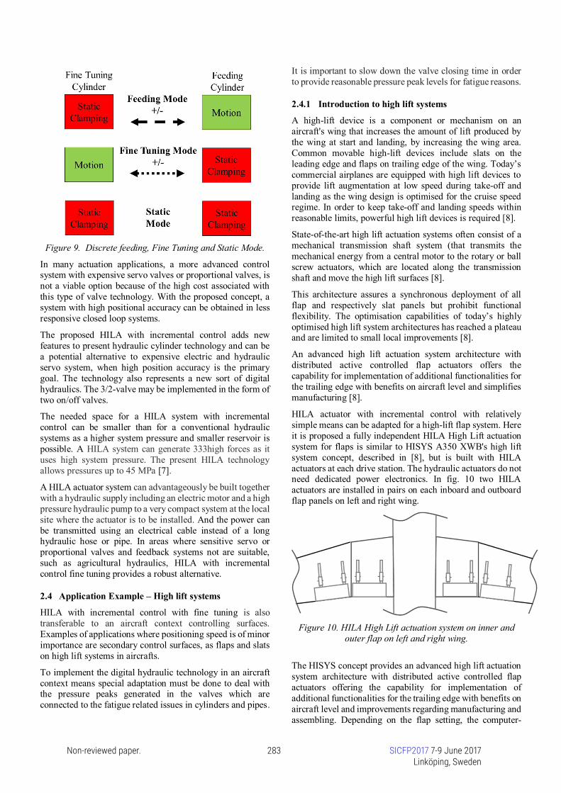
Figure 9. Discrete feeding, Fine Tuning and Static Mode.
In many actuation applications, a more advanced controlsystem with expensive servo valves or proportional valves, isnot a viable option because of the high cost associated withthis type of valve technology. With the proposed concept, asystem with high positional accuracy can be obtained in lessresponsive closed loop systems.
The proposed HILA with incremental control adds newfeatures to present hydraulic cylinder technology and can bea potential alternative to expensive electric and hydraulicservo system, when high position accuracy is the primarygoal. The technology also represents a new sort of digitalhydraulics. The 3/2-valve may be implemented in the form oftwo on/off valves.
The needed space for a HILA system with incrementalcontrol can be smaller than for a conventional hydraulicsystems as a higher system pressure and smaller reservoir ispossible. A HILA system can generate 333high forces as ituses high system pressure. The present HILA technologyallows pressures up to 45 MPa [7].
A HILA actuator system can advantageously be built togetherwith a hydraulic supply including an electric motor and a highpressure hydraulic pump to a very compact system at the localsite where the actuator is to be installed. And the power canbe transmitted using an electrical cable instead of a longhydraulic hose or pipe. In areas where sensitive servo orproportional valves and feedback systems not are suitable,such as agricultural hydraulics, HILA with incrementalcontrol fine tuning provides a robust alternative.
2.4 Application Example – High lift systems
HILA with incremental control with fine tuning is alsotransferable to an aircraft context controlling surfaces.Examples of applications where positioning speed is of minorimportance are secondary control surfaces, as flaps and slatson high lift systems in aircrafts.
To implement the digital hydraulic technology in an aircraftcontext means special adaptation must be done to deal withthe pressure peaks generated in the valves which areconnected to the fatigue related issues in cylinders and pipes.
It is important to slow down the valve closing time in orderto provide reasonable pressure peak levels for fatigue reasons.
2.4.1 Introduction to high lift systems
A high-lift device is a component or mechanism on anaircraft's wing that increases the amount of lift produced bythe wing at start and landing, by increasing the wing area.Common movable high-lift devices include slats on theleading edge and flaps on trailing edge of the wing. Today’scommercial airplanes are equipped with high lift devices toprovide lift augmentation at low speed during take-off andlanding as the wing design is optimised for the cruise speedregime. In order to keep take-off and landing speeds withinreasonable limits, powerful high lift devices is required [8].
State-of-the-art high lift actuation systems often consist of amechanical transmission shaft system (that transmits themechanical energy from a central motor to the rotary or ballscrew actuators, which are located along the transmissionshaft and move the high lift surfaces [8].
This architecture assures a synchronous deployment of allflap and respectively slat panels but prohibit functionalflexibility. The optimisation capabilities of today’s highlyoptimised high lift system architectures has reached a plateauand are limited to small local improvements [8].
An advanced high lift actuation system architecture withdistributed active controlled flap actuators offers thecapability for implementation of additional functionalities forthe trailing edge with benefits on aircraft level and simplifiesmanufacturing [8].
HILA actuator with incremental control with relativelysimple means can be adapted for a high-lift flap system. Hereit is proposed a fully independent HILA High Lift actuationsystem for flaps is similar to HISYS A350 XWB's high liftsystem concept, described in [8], but is built with HILAactuators at each drive station. The hydraulic actuators do notneed dedicated power electronics. In fig. 10 two HILAactuators are installed in pairs on each inboard and outboardflap panels on left and right wing.
Figure 10. HILA High Lift actuation system on inner andouter flap on left and right wing.
The HISYS concept provides an advanced high lift actuationsystem architecture with distributed active controlled flapactuators offering the capability for implementation ofadditional functionalities for the trailing edge with benefits onaircraft level and improvements regarding manufacturing andassembling. Depending on the flap setting, the computer-
Non-reviewed paper. 283 SICFP2017 7-9 June 2017Linköping, Sweden

controlled spoiler automatically moves into the most efficientposition during cruise flight. Drag can be reduced by up totwo per cent at high gross weights, resulting in considerablefuel economies. Weight savings on the order of half a tonnefor the wing box are feasible by using differential flap settingsto alleviate loads by changing the centre of lift for loadsmanagement [8]. HILA concept also has the same functionalbenefits and reduced manufacturing effort as the HISYSconcept.
2.5 Requirements on a high lift hydraulic actuator
The requirements that characterize a hydraulic actuator for ahigh-lift flap applications are as follows:
- High demands on position accuracy- Relatively high air loads, but no mass inertia- High stiffness- Low operating actuator speed- Lightweight and compact design- High reliability, a failsafe solution and a high abilityto detect errors- Non-complex control algorithm- No high pressure peaks during operation. Soft startand stop of cylinder manoeuvring.- Parallel and synchronous movement of the actuators- Low temperature
2.6 HILA High Lift System
The proposed high lift system with differential flap setting,enables optimization of the cruise aerodynamic efficiencyand loads through the control of the wing centre of the liftposition by differentiating the inner and outer flap. Theproposed flap system can be actuated by an electric drivensystem with ball-screws or a HILA High Lift system, asshowed in fig. 11, fig. 12A and 12B.
Figure 11. Incremental motion with a feeding HILA cylinderin combination with a fine tuning/trim HILA cylinder.
With HILA technology flap movement is made during take-off and landing in discrete incremental steps of 2-4 degrees,extending the wing area, as described in previously chapters,with simple, proven and robust ordinary on/off anddirectional valves. In cruise mode the technology enables trimcapability with small incremental steps for fuel saving andload optimization using the fine tuning cylinder.
(A)
(B)
Figure 12. HILA cylinder installed between the wing andthe high lift flap surface.
The feature of this solution is that the compact and leak-freecylinders combined with well-known clamping technology isused. Further a simplified wing design is provided, norotating and bending shafts along the wing spar are required.
Furthermore, the concept is relatively simple to monitoringwith detectable faults. At every start a Pre-Flight Built In Testis performed.
The system provides fail-safe position upon failure of thehydraulic and/or electric power, and at flap asymmetries. Themaintenance of the hydraulic system are less demanding andless frequent in comparison with electric ball screw, which isimportant from a LCC perspective.
With well-known clamping technology and incrementalcontrol HILA innovation provides a new, robust and cost-effective high lift flap system that is simple in its design andprovides both high-lift at start and landing also trim of flapposition in cruise mode. This normally requires expensive,complex and maintenance intensive electrical or hydraulicactuation systems. HILA High Lift actuation technology canalso be used on the leading edge slat system.
2.7 Redundancy with HILA technology
There are a number of fault cases that are handled in a failsafeway with sufficient redundancy in the actuator system and ona system level with HILA technology.
2.8 Loss of hydraulic and / or electric power
To handle faults the design has been supplemented with asmall accumulator and a check valve, see fig. 11. In the eventof loss of hydraulic and/or electrical power, hydraulicpressure on the static clamping element can be maintained bymeans of a small accumulator and a check valve.
2.9 Asymmetry and jamming
To ensure that the two systems HILA on respective flap panelare working in parallel and synchronously there are different
Fine Tuning / Trim CylinderShort stroke
Feeding CylinderLong stroke
- +Trim
SmallAccumulator
Non-reviewed paper. 284 SICFP2017 7-9 June 2017Linköping, Sweden

ways to detect failures together with a position sensor on eachactuator.
A simple solution is provided by proximity switches at theend positions of the pistons. If the switching in the proximityswitches in the right and left system do not occursimultaneously (some tenths of ms can be tolerated) a monitordetect the motion asymmetry between right and left system.
Another way to ensure the fault occurs, is to compare thehydraulic pressure in the cylinder chambers in the left andright actuator during motion. If the pressure differs too muchfrom each other means that different speeds in the respectivecylinder and a risk of jamming exists. A frozen state will becommanded and the flap panel remains in its fixed positionthroughout the remaining flight.
2.10 Hydraulic system failure
Normally a flight hydraulic system has two independenthydraulic systems (HS1 and HS2). The high lift system issupplied with hydraulic power from one hydraulic system,here HS1. In the event of failure of HS1, HS2 is commandedto supply the system through an emergency valve and theshuttle valve, according to fig. 13.
Figure 13. HILA High Lift flap system with left and rightactuators, supplied normally from HS1 and in emergency
case from HS2.
2.11 Pressure peaks
It is important to control the directional valves, included inHILA High Lift system, avoiding pressure peaks andcavitation during the stopping. It can be done by using asuitable opening area gradient in the directional valve. But itcan also be combined with end position cushioning. Endposition cushioning ensures a controlled deceleration of thestroke velocity in both end positions. This means that theactuator will not “bang” into hard-stops or jolt. This cushionseliminates stress on the actuator elements. The movementscan be smoother.
3 HILA technology with multiple rods
3.1 Controlling multiple rods in the same commonpiston
The separate pressurization of the clamping element opens upthe possibility to control the movement of multiple individuallinear piston rods in the same common piston.
Here it is proposed a solution in which multiple piston rodsare using the same piston. A common hydraulic pistontransfer simultaneous movement to a number of piston rods.Each piston rod is connected individually to the commonpistons with individual clamping elements or of individualstatic clamping member by means of individual logic valves(see fig. 14 and 15). A common servo valve or directionalvalve controls the common piston.
Why gather a number of piston rods in the same piston? Thisway of arranging actuator movement has advantages but alsopresent some limitations, among others regardingcontrollability.
In following chapter a number of ways of using thistechnology in different applications will be presented.
The technology is called HILA with Multiple Rods (HILAMR). HILA MR enables a completely new way to generateand distribute mechanical linear movement and force byusing hydraulic actuators.
Figure 14. Six individual pistons integrated in two commonpistons.
In areas where there are a great need for compact and energy-efficient drive units for multiple linear actuation are requiredHILA MR technology can be a suitable alternative. HILA MRenables a very compact, lightweight and cost-effectivemultiple actuation, especially if high hydraulic pressure canbe used.
HS1 HS2
Non-reviewed paper. 285 SICFP2017 7-9 June 2017Linköping, Sweden

3.2 Ability to maintain static load for long time
Multiple static clamping elements integrated in commonpistons together can individually perform piston rodmovements in different directions. Combined with anoptional static clamping element, this arrangement also hasan ability to keep a high static load for a long period withalmost no energy consumption. Equivalent solution forelectric actuators, which do not use self-locking gears such asscrewballs, requires a constant supply of current to hold theload.
In some applications, a static clamping in combination withHILA MR technology is very useful. With a static clamping,for example in a robot hand or gripper application, quick andprecise positioning with low forces can be combined withhigh static forces for a long time. In order to control multiplerods with different requirements regarding movement andrest a static clamping unit is needed, see fig. 15 below. Thestatic clamping element provides a parking mode for pistonsrod which not are in motion.
Figure 15. Hydraulic schematic of HILA MR
3.3 Separate pressurization with micro-valves
A 3/2 micro-valve controls the pressurization of therespective piston rod clamping elements. It has a switchingtime of a few milliseconds. Small valves with low powerconsumption and low flow capacity can be used because themembrane in the clamping element needs a very smallvolume change during pressurization and clamping.
Figure 16. Individual pressurisation of each clampingelement in common piston with micro-valves
With a small electric control current in the micro-valve, alarge axial force in the piston can be controlled in a simpleway (see fig. 16). A large mechanical force in the individualpiston rod can be controlled by the micro-valve in a mannersimilar to how a small gate current in an electrical transistorcan control a much larger current. Micro-valves may beplaced as an extension of the part of the protruding piston,outside the cylinder. The supply of hydraulic power to thevalves is done via a common thin hose and a thin electricmulti cable. In order to decrease the clamping element area ahigher control pressure may be used. The used clampingtechnology allows clamping pressures up to 45 MPa [7]. The3/2 micro-valve may be implemented in the form of twoon/off valves.
3.4 Thermal Handling
A well-known problem with electric actuators is that theycannot permanently be hold in a position to keep a high load,because they soon become detrimental warm and at the sametime as they consume a lot of electric energy (if they do notuse a self-locking gear). In a hydraulic circuit, the dissipatedheat in the oil can be efficiently cooled off in an oil cooler.
HILA MR technology can handle thermal issues much betterthan comparable electric alternatives, due to the constantlycirculating oil. Especially in applications where continuous24/7 operation is demanded and/or in applications installed incramped spaces where no cooling baffle fits, e.g. in a roboticlimb, hand or gripper. The risk for overheating which candamage the actuator is low as the generated heat energy istaken away by the circulating oil. In an electric actuator, theheat transport to the air take place locally with bulky airbaffles and/or fans.
Static Clamping Unit Cylinder 1 Cylinder 2Rod 1Rod 2Rod n
Non-reviewed paper. 286 SICFP2017 7-9 June 2017Linköping, Sweden
3.5 No external leakage and lateral forces
Figure 17. Piston rods not centrally located
The proposed method to locate the rods in the piston, meansthat all the rods are not centrally located, but distributedradially from the center, see fig. 17. That means that sidelateral forces are generated in the piston if the transferredaxial forces in the individual piston rod are not balanced.Lateral forces or side loading is a common cylinder problemthat normally leads to premature failure. Lateral forces on acylinder rod, particularly when the rod is extended, candamage the cylinder and shorten its useful life. Eventually,seals will suffer damage, resulting in external fluid leaks andseal failure.
Lateral forces on the common piston which occurs, can behandled in a non-destructive way by using bronze bearings ina similar way that they are used in hydraulic in-line machines,instead of using rubber sealings.
Introducing bearings, instead of using rubber sealings,provide advantages but also drawbacks, which are solvable.Among them leakage. Hydraulic equipment in general, andhydraulic cylinders especially are leaking oil externally whenthey are pressurized and work. This is one of the biggestdrawbacks in hydraulics and a challenge to handle.
The friction is also higher in a symmetric cylinder than in aconventional asymmetrical cylinder, due to double endsealings. In order to design a power efficient system it isessential to minimize these friction losses and also to achievebetter speed performance.
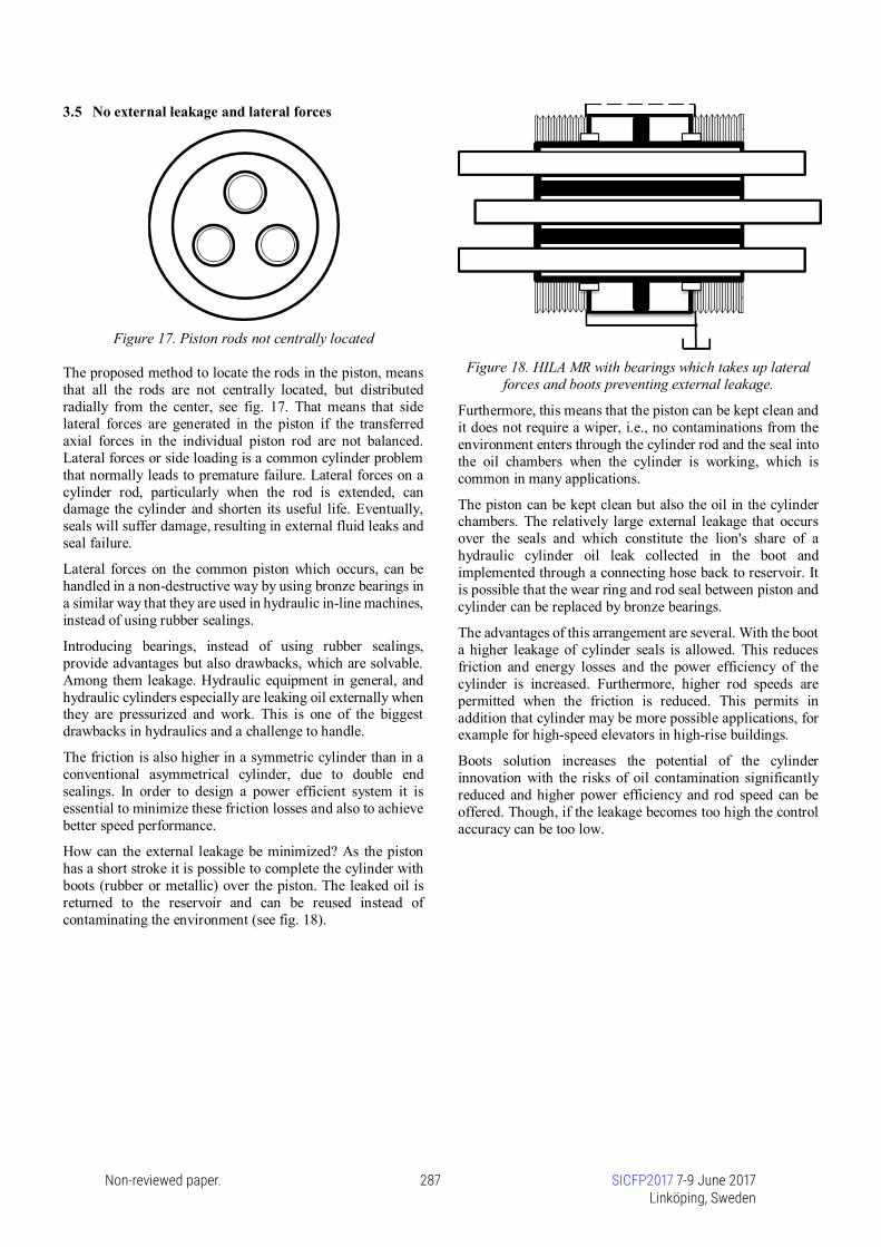
How can the external leakage be minimized? As the pistonhas a short stroke it is possible to complete the cylinder withboots (rubber or metallic) over the piston. The leaked oil isreturned to the reservoir and can be reused instead ofcontaminating the environment (see fig. 18).
Figure 18. HILA MR with bearings which takes up lateralforces and boots preventing external leakage.
Furthermore, this means that the piston can be kept clean andit does not require a wiper, i.e., no contaminations from theenvironment enters through the cylinder rod and the seal intothe oil chambers when the cylinder is working, which iscommon in many applications.
The piston can be kept clean but also the oil in the cylinderchambers. The relatively large external leakage that occursover the seals and which constitute the lion's share of ahydraulic cylinder oil leak collected in the boot andimplemented through a connecting hose back to reservoir. Itis possible that the wear ring and rod seal between piston andcylinder can be replaced by bronze bearings.
The advantages of this arrangement are several. With the boota higher leakage of cylinder seals is allowed. This reducesfriction and energy losses and the power efficiency of thecylinder is increased. Furthermore, higher rod speeds arepermitted when the friction is reduced. This permits inaddition that cylinder may be more possible applications, forexample for high-speed elevators in high-rise buildings.
Boots solution increases the potential of the cylinderinnovation with the risks of oil contamination significantlyreduced and higher power efficiency and rod speed can beoffered. Though, if the leakage becomes too high the controlaccuracy can be too low.
Non-reviewed paper. 287 SICFP2017 7-9 June 2017Linköping, Sweden

3.6 Common position sensor
Figure 19. A HILA MR combination with a common staticclamping unit and a common cylinder with clamping
elements and a position sensor in the moving common piston(Pcom) (dotted line = pressurised clamping elements).
The common piston (Pcom) that work partially outside thecylinder housing can be equipped with a position sensor forfeedback control (see fig. 19). The position sensor can be ofdifferent types, e.g. LVDT, potentiometer, etc.
In fig. 19 rod A (RA) is clamped to the moving common piston(Pcom). Rod B and C are static clamped. The relative motionwhich is done with rod A clamped to the common piston iscalculated.
This relative position information, using an embeddedcomputer, is used to estimate the absolute position for rod Aand for each piston rod which is moved. This positioninformation is essential for a control system. The commoncommon position sensor means that a large number ofindividual position sensors can be eliminated. Thisarrangement avoids a lot of different failure modes and savesvolume, weight and cost.
The position information from the common position sensormust be complemented with different types of positionsynchronization of the respective piston rod and built-in teststo ensure that the location information for each rod can betrusted at every time. At start up all piston rods can bepositioned at a hard stop with a known position and then besynchronized. If not repeated synchronizations are performedyou cannot rely on the information from the common positionsensor.
It is also of great importance that no micro slip occursbetween the rod and the common piston at clamping andunclamping. This risk is minimized if clamping andunclamping takes place when the piston and piston rod isstationary still or have the same speed.
3.7 Infinite stationary hydraulic stiffness
The considered concept, HILA MR, allows moving the pistonwithout moving the disengaged rods. Thus when the desiredrod positions are reached the disengaged piston can be movedto one of its end stops. After engaging the cylinder andpressurizing the one cylinder chamber to push the pistonagainst the end stop the elasticity of the mechanical contact is
dominating the cylinder stiffness, see fig. 20. Thus thehydraulic stiffness becomes infinite. In this consideration theelasticity of all mechanical components like structure and rodare neglected [4].
Figure 20. Two cylinders at opposed side end stops, withinfinite stiffness.
3.8 Hydraulic Time Sharing
HILA MR technology enables time sharing and a loadsensing.
By using a time sharing strategy for the individual piston rodmovements advantages can be obtained. If a piston rod ismoved at a time and the other piston rods are in static modefollowing advantages is obtained: The common piston areacan be reduced. The force of the piston rod having largestforce demand determines the common piston area. Thecommon piston area can be reduced and the cylinder can bedesigned more compact and lightweight. Also the supplysystem can be designed with lower power requirements.
3.9 Time sharing hydraulics in an unmanned aircraft
A suitable field for the proposed time sharing hydraulictechnology with HILA MR technology is in unmannedaircrafts.
An aircraft has a number of subsystems containing hydraulicactuators, among others, flight control system, landing gearsystem and fuel system. A Medium-Altitude Long-Endurance(MALE) unmanned aircraft, which flies autonomously hasbeen selected as a suitable application.
The flight control system can be divided into primary andsecondary control surfaces. The primary control surfacesconsist of ailerons, elevators and a rudder and its task is tomaintain the aircraft's stability at disturbances that occur inflight and control the aircraft in pitch, roll and yaw of apredetermined flight trajectory.
The rudder commands to maintain stability are time-criticaland unpredictable due to wind gust and side winds, i.e. theymust be executed without delay, and they have the highestpriority. Commands for control in pitch, roll and yaw are lesstime-critical and follows in order of priority. Lower priorityhas the operation of secondary control surfaces, the flaps forhigh lift, and the landing gear actuation, which if necessarycan be divided into phases
Besides the rudder commands required to maintain stability,the other commands can planned in advance as they arepredictable and less or not time-critical. These commandsneed not to be performed in parallel, but they may be
Non-reviewed paper. 288 SICFP2017 7-9 June 2017Linköping, Sweden

commanded in series. This is possible in an UAV when a pilotis not present in the control loop.
Figure 21. A MALE UAV with HILA MR technology
In most aircrafts there are active rudder activities only duringa few percent of a total flight, especially during long distanceflights. Under these conditions a time sharing hydraulicssystem is preferable. Rudder and landing gear commands canbe executed in series. In case of a wind disturbance, thesecondary control surfaces and/or landing gear manoeuvringcan be stopped temporarily, in order to move the primarycontrol surfaces and stabilize the aircraft.
With this conditions, a hydraulic actuator system based onHILA MR technology and a hydraulic supply system can bedesigned, which has low power demand, is more compact,lighter, more energy efficient, and not least cost-effective.HILA MR technology, can here be used here in combinationwith wire cables that transfer power and motion to therespective consumer. Wire technology has been used formany decades in aviation, controlling surfaces. See fig. 21.
In the design of hydraulic systems in mobile vehicles, and inparticular, in an aircraft, a large focus is on minimizingsystem weight and energy consumption. In aviation, thedemands on system safety is high, but for space reasons it is
not described here how the system can be built fault tolerantwith redundant solutions.
4 HILA MR with incremental controlHILA MR technology can be combined with the incrementalcontrol methods introduced in earlier chapters. There areinteresting applications for this combination in the roboticsfield, which will be presented and analysed in this chapter. Itwill also be conceptually shown that in this field, HILA MRwith incremental control enables more accurate and timeefficient methods for positioning.
4.1 Robot applications
HILA MR technology is particularly suitable for applicationswhere multiple actuator functions with high requirements ofstrength and stiffness have to be implemented in confinedspaces. This requirements is common in robot applications,such as articulated robot and snake-like robots where also aless responsive closed loop system can be used.
4.2 Description of the base element
HILA MR technology enables a flexible, compact and rigidactuator, which is highly desirable in design of articulatedrobots arms or snake-like robots. This is provided bymanoeuvring four piston rods simultaneously in a robot armsegment.
An articulated robot arm uses rotary joints to access its workspace. Between the joints there are rigid links. The joints andlinks are arranged in a kinematic chain, so that one jointsupports another joint via the link or spacing section in thechain. The terminus of the kinematic chain of the robot armis called the end effector. As end effector a gripper, a devicefor grasping or holding a payload, or a tool, is normally used.
The rotary joint between the sections allows rotationalmotion. The flexibility of robot arms depends of the rotationalability between each section. Most robot arms in anarticulated robot only have one axis in a single section, whichis equal to one degree of freedom (DOF). In order to get betteraccess to confined spaces access a universal joint ispreferable. HILA MR technology enables a joint with twoDOF, both in pitch and yaw, see fig. 22, in each center ofrotation.
Figure 22. Actuation in pitch and yaw rotational directionat left and right end of the robot arm segment.
In many applications a robot arm should provide also highaccuracy, repeatability, resolution and speed.
The resolution is the smallest increment of motion or distancethat can be detected or controlled by the control system of therobot arm.
Non-reviewed paper. 289 SICFP2017 7-9 June 2017Linköping, Sweden
The best solution with respect of these requirements is toprovide a hydraulic servo valve. It is not always possible toprovide a servo valve for control of the respective piston rodbecause of cost and space reasons.
In some applications with less responsive closed loopsystems, but with high resolution and high position accuracyrequirements, an incremental control may be a better solution.
Here it is described such a robot arm solution where HILAMR with incremental control is used with a fine tuningcylinder and a feeding cylinder, see fig.23.
Figure 23. Rotational actuation in a segment of snake-robotarm construction with HILA MR with incremental control.
In order to employ twin rotary actuation system and two DOFin each robot arm segments end and maintain stiffness andcompactness a new snake arm robot construction is useddescribed in [10] using stiff actuation cables and wheels toclose the force loop.
One cable in a pair of actuation cables pulls a distance and theother cable in this pair extracts the same distance, whichcauses the bending deformation of the compliant joints andholds the cables of this pair in tension in any kinematicconfiguration [10]. Here it is proposed that the cable isactuated by HILA technology instead of an angular actuator.
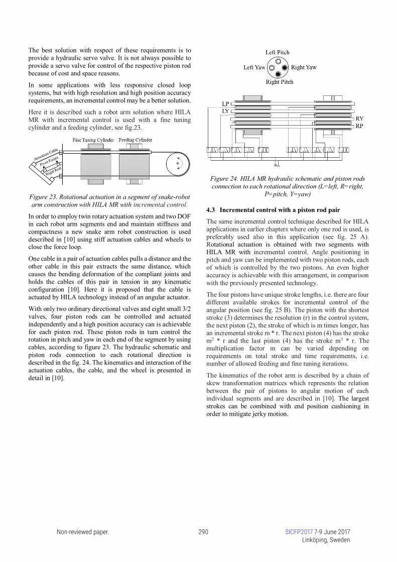
With only two ordinary directional valves and eight small 3/2valves, four piston rods can be controlled and actuatedindependently and a high position accuracy can is achievablefor each piston rod. These piston rods in turn control therotation in pitch and yaw in each end of the segment by usingcables, according to figure 23. The hydraulic schematic andpiston rods connection to each rotational direction isdescribed in the fig. 24. The kinematics and interaction of theactuation cables, the cable, and the wheel is presented indetail in [10].
Figure 24. HILA MR hydraulic schematic and piston rodsconnection to each rotational direction (L=left, R=right,
P=pitch, Y=yaw)
4.3 Incremental control with a piston rod pair
The same incremental control technique described for HILAapplications in earlier chapters where only one rod is used, ispreferably used also in this application (see fig. 25 A).Rotational actuation is obtained with two segments withHILA MR with incremental control. Angle positioning inpitch and yaw can be implemented with two piston rods, eachof which is controlled by the two pistons. An even higheraccuracy is achievable with this arrangement, in comparisonwith the previously presented technology.
The four pistons have unique stroke lengths, i.e. there are fourdifferent available strokes for incremental control of theangular position (see fig. 25 B). The piston with the shorteststroke (3) determines the resolution (r) in the control system,the next piston (2), the stroke of which is m times longer, hasan incremental stroke m * r. The next piston (4) has the strokem2 * r and the last piston (4) has the stroke m3 * r. Themultiplication factor m can be varied depending onrequirements on total stroke and time requirements, i.e.number of allowed feeding and fine tuning iterations.
The kinematics of the robot arm is described by a chain ofskew transformation matrices which represents the relationbetween the pair of pistons to angular motion of eachindividual segments and are described in [10]. The largeststrokes can be combined with end position cushioning inorder to mitigate jerky motion.
Non-reviewed paper. 290 SICFP2017 7-9 June 2017Linköping, Sweden

Figure 25. Incremental angular control in one DOF of twointerconnected robot segments.
Fig. 25 C shows the different main modes: Feeding Mode,Fine Tuning Mode and Static Mode. In Feeding Mode ispiston 2 and 3 active and clamped to the piston rod, in thesubsequent Fine Tuning Mode, piston 1 and 4.
The work sequence of the incremental angular control in oneDOF of two interconnected robot segments is as follows. Tobegin with, piston 1 and 4 work with positioning left and rightpiston rod and actuation cables in the Fast Feeding Mode. Thelonger movements of the piston rods occurs here. Then thereis a changeover to the Fine Tuning Mode and piston 2 and 3position piston rods and actuation cables are moved until thecommanded angle is obtained. It is important to note that thepiston rods movements can occur in both directions.
An angular position sensor, not shown in figure 25A, closesthe control loop including appropriate filters. The controlloop will also include corrective commands in order to reachthe commanded angle position. Finally in the Static Modeall pistons are clamped to the piston rod pair, enabling highstiffness.
Figure 26. Example of rotational actuation enabling highagility.
Here it is showed that an incremental control strategy with afew large and small incremental steps available in fourdifferent pistons, can provide a powerful combination of highangle resolution and a large total angle stroke, enabling a highagility. The robot arm segments can be built together in seriescreating a snake-like robot capable of working in confinedspaces and reach the farthest ends of the cavities of forexample an aircraft while maintaining the rigidity andprecision all the way to the end effector, see fig. 26 and 28.Also a combination with segments with HILA MR withincremental control and slave segments is a feasible solution.
4.4 Need for slim snake-like robots
Assembling modern aircrafts is, in many ways, still as muchof a craft as 18th century shipbuilding, requiring loads of skilland manual labour to get the job done, because the neededindustrial robots are too inflexible and reach too short [9].There is a need for snake-like robots and lot of uses in severalindustrial segments today, beyond aircraft manufacturing, inautomotive industry, in nuclear power plants, off-shoreplatforms, shipbuilding, laparoscopic surgery etc. But theserobots are not on the market today, however there are somedemonstrators.
Figure 27. A snake-like robot in a wing tank (Image:FRAUNHOFER IWU).
Present articulated 6-, 7-axis electrical or hydraulic robots aretoo clumsy, especially in turning points, for this applicationstoday. It requires distinct robotic arm movements performed
Non-reviewed paper. 291 SICFP2017 7-9 June 2017Linköping, Sweden

by slim, multi joint robotic arms in tight spaces, avoiding tocollide with walls in confined spaces, see fig. 27.
A large number of snake arm robot designs have beenpresented, but there is no snake robot that can carry arelatively large payload, while having small diameter/lengthratio, great flexibility (bending capability) and a compactactuation system [10].
Robot arm segments, based on HILA MR with incrementalcontrol, can be designed as a snake-like robot, which consistsof several series-connected elements. This robot is capable ofworking in confined spaces and reach the furthest ends of thecavities, for example, in an aircraft wing while maintainingthe rigidity and precision all the way to the end effector. Thesnake-like HILA robot can be divided into a part that looksmore like a jig, which is not operated so frequently, and a partnear the end effector which is more like an industrial robot.HILA MR with incremental control can be used especially inparts which are less frequently operated and rapid movementsare not so needed.
Figure 28. A snake-like HILA robot capable of working inconfined spaces.
5 DiscussionHILA and its various combinations represents a quitedifferent approach compared to conventional hydrauliccylinder technologies. The barrier is high to introduce newtechnology in the conservative hydraulic cylinder industry,mainly because established technology is so widelyaccepted. However, this industry needs new inventions todefend shrinking market segments [11].
Research has been carried out during several years in thefield of digital hydraulic actuation. A number of promisingconcepts characterised by robustness, simplicity andreliability have been proposed. But commercialbreakthrough has not yet been achieved, mainly due to thehigh number of needed on/off-valves and physical size andweight of the valve package.
HILA represents a new sort of digital hydraulics, especiallyHILA equipped with incremental control with discreteactuator stepping instead of switched valves. Various HILAtechnologies and concepts presented in this paper are based
on few micro valves, which are working as a hydraulictransistor in each actuator. However, these high pressure andfast switching control valves require extremely low flow.HILA offers a miniaturisation of the control valve packageand a neat design compared to present digital hydraulicsystems.
6 Future WorkThis conceptual paper presents a part of the current state ofHILA development project. The basic functionality of HILAtechnology has successfully been proved in earlier modelsimulations and rig tests (see alsohttps://m.youtube.com/watch?v=UCO-OQOdxtg). However,the work presented in this paper will be further enhanced bysimulation and laboratory tests. Such future work mayinclude that incremental control system needs to bemodelled and simulated for different load and speed cases.The simulations will be done with and without mass inertiatogether with appropriate regulator structures, such as PIDcontrol, in order to minimise potential jerkiness and fatigueissues.
Another area of importance for further research work isfinding suitable applications for proposed HILAtechnologies. This may include completely new applicationsfor hydraulic cylinders in materials handling and mobileapplications. All areas suitable for the variants of HILAdescribed in this paper have not been identified fordevelopment efforts and research.
It is also important to identify industries that are in adynamic development phase, and thus interested in newinnovations in these areas. These may be found outside thetraditional industries for hydraulic cylinders. To succeed inresearch with HILA, the technology also has to be presentedto industries which today use electrical actuators to a largeextent. Such an industry is the growing robot industry.HILA can offer the robot industry a more cost-effective andsuitable technology for some applications, such as snake-like robots, where current electrical actuators do not fullymeet the requirements for that application.
7 ConclusionsIn this paper a number of concepts of HILA technology arepresented. The basic invention is a hydraulic cylinder with areleasable piston. It is based on a well-known hydraulicclamping element used in a new combination, where thepiston and the piston rod can quickly be coupled anduncoupled by means of the clamping element, in a failsafeway. The invention provides new features to hydrauliccylinders such as providing very long strokes, high rodspeed, and small chamber volumes enabling high pressurewhich means high stiffness and low capacitance. Thetechnology also represents a new sort of digital hydraulics,especially the variant with incremental control. The studypresents feasible combinations of the technology.
HILA with incremental control, using ordinary directionalvalve and on/off valves, adds new features to present
Non-reviewed paper. 292 SICFP2017 7-9 June 2017Linköping, Sweden

hydraulic cylinder technology and can be a potentialalternative to expensive electric and hydraulic servosystems, when high position accuracy is the primary goalwithin less responsive closed loop systems.
HILA with multiple rods (HILA MR) technology ispresented for the first time in this paper, enables acompletely new and novel way to generate and distributemechanical linear movement and force by using hydraulicactuators, maintaining high pressure, compactness andenergy efficiency. A single position sensor on the commonpiston can be used to determine the absolute position of theindividual piston rod.
In less responsive closed loop systems, HILA with multiplerods and incremental control enables a new way to generateand distribute mechanical linear movement and force byusing hydraulic actuators in a cost effective way. Multipleactuating elements together with incremental control,integrated in a compact and lightweight single unitcontrolled by ordinary directional valves enables a highposition accuracy.
In the robotic area a high agility robot configuration thatmay carry a reasonable load, with a small diameter andlength ratio, is needed in several areas, such as nuclearpower plants, off-shore platforms, shipbuilding,laparoscopic surgery etc. The robot has to be capable ofworking and navigating in confined spaces and reach thefurthest ends of the cavities, for example in a wing tank, acollapsed building or in military operations.
HILA with multiple rods and incremental control enables apromising solution for these issues. With large and smallincremental steps executed in two linked robot armsegments, it will be able to have a more accurate and timeefficient method for angle positioning in pitch and yaw. Thesegments can be built together in series for snake-like robotapplications.
HILA technology is patent pending.
8 AcknowledgmentsThis work was sponsored by Saab AB and the SwedishEnergy Agency.
9 References[1] K.-E. Rydberg,”Hydraulic servo systems”,
https://www.iei.liu.se/flumes/tmhp51/filearchive/coursematerial/1.105708/HydServoSystems_part1.pdf, pp. 3,2008
[2] M Landberg, M Hochwallner, and P Krus, “Novel LinearHydraulic Actuator”. ASME/BATH 2015 Symposiumon Fluid Power & Motion, Chicago, United States
[3] J Li, “Design and development of a piezoelectric linearactuator for smart structures”, Department of Mechanicaland Industrial Engineering, Concordia University,Montreal, Quebec, Canada, 2004
[4] M Hochwallner, M Landberg, and P Krus, “TheHydraulic Infinite Linear Actuator – properties relevantfor control”. In 10th International Fluid PowerConference (10. IFK), Vol. 3, pp. 411–424, 2016
[5] S Mraz, “Comparing Electric Rod Actuatorsand Hydraulic Cylinders”, Machine Design,http://machinedesign.com/technologies/hydraulics, 2016
[6] M Linjama, “DIGITAL FLUID POWER –STATE OFTHE ART”, The 12th Scandinavian InternationalConference on Fluid Power, Tampere, FinlandLinköping, 2011
[7] ETP-OCTOPUS, ETP Transmission AB,www.etptrans.se
[8] M Recksiek, “ADVANCED HIGHLIFT SYSTEM ARCHITECTURE WITHDISTRIBUTED ELECTRICAL FLAP ACTUATION”,AST 2009, Hamburg, Germany
[9] “Automated assembly of aircraft wings” ,https://www.fraunhofer.de/en/press/research-news/2014/may/automated-assembly-of-aircraft-wings.html
[10] X Dong, M Raffles, S Cobos Guzman, D Axinte, J Kell,“Design and analysis of a family of snake arm robotsconnected by compliant joints”, Mechanism andMachine Theory 77 (2014) 73–91
[11] “Hydraulic Cylinders Industry Report”, July 2013,InterOcean Advisors LLC, 117 North Jefferson Street,Suite 205, Chicago, IL 60661, www.ioadvisors.com
Non-reviewed paper. 293 SICFP2017 7-9 June 2017Linköping, Sweden


![Performance Enhancements analysis and proposals Draft 2010-06-21 Adrian Pop [Adrian.Pop@liu.se]Adrian.Pop@liu.se.](https://static.fdocuments.us/doc/165x107/56649e7d5503460f94b7ffb4/performance-enhancements-analysis-and-proposals-draft-2010-06-21-adrian-pop.jpg)


