The GW detector Mario Schenberg -...
57
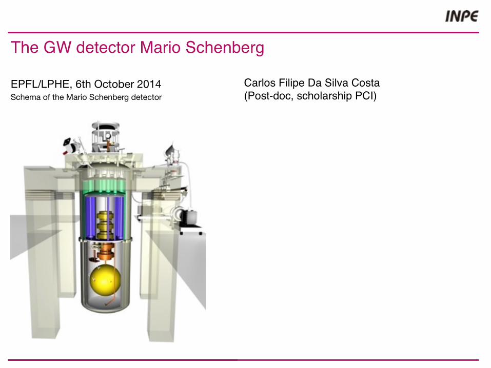
Carlos Filipe Da Silva Costa (Post-doc, scholarship PCI) The GW detector Mario Schenberg EPFL/LPHE, 6th October 2014 Schema of the Mario Schenberg detector
Transcript of The GW detector Mario Schenberg -...
EPFL/ LPHE 6th Oct. 2014, C.F. Da Silva Costa
The Mario Schenberg detector
1
Carlos Filipe Da Silva Costa(Post-doc, scholarship PCI)
The GW detector Mario Schenberg
EPFL/LPHE, 6th October 2014Schema of the Mario Schenberg detector

EPFL/ LPHE 6th Oct. 2014, C.F. Da Silva Costa
The Mario Schenberg detector
2
The next 3 years (max 2022) will be decisive for the gravitational waves: first detection?
If yes, you will have an incredible amount of information about astrophysical phenomena.
The GW detector Mario Schenberg

EPFL/ LPHE 6th Oct. 2014, C.F. Da Silva Costa
The Mario Schenberg detector
3
- A brief introduction to GW - Which kind of detectors- Mario Schenberg, a close view- Present activities before the RUN!- What we (I) hope for the future- Conclusions
Plan
Schema of the Mario Schenberg detector

EPFL, 6th Oct. 2014, C.F. Da Silva Costa
Mario Schenberg detector
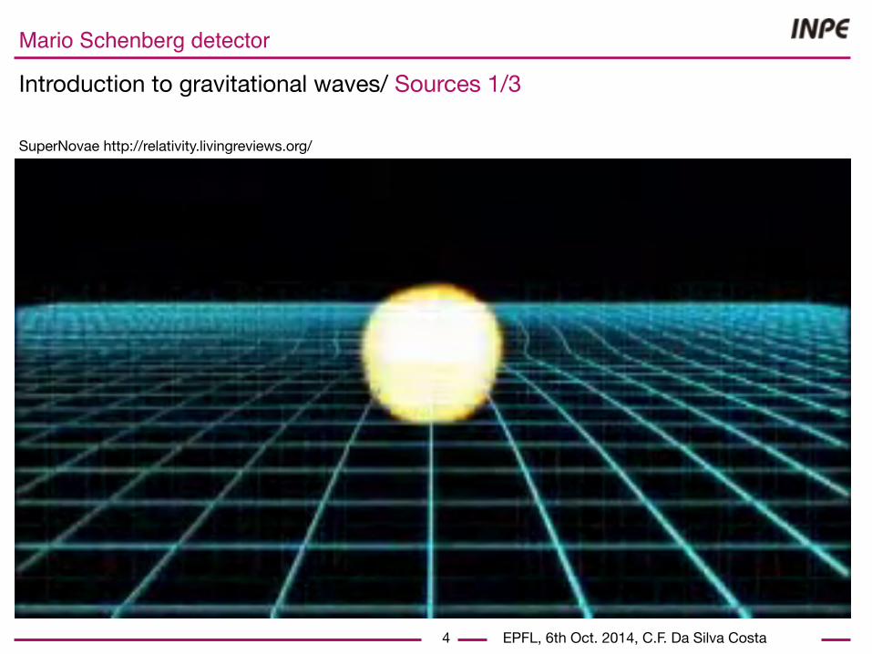
Introduction to gravitational waves/ Sources 1/3
4
SuperNovae http://relativity.livingreviews.org/
EPFL, 6th Oct. 2014, C.F. Da Silva Costa
Mario Schenberg detector
Introduction to gravitational waves/ Sources 1/3
4
SuperNovae http://relativity.livingreviews.org/

EPFL, 6th Oct. 2014, C.F. Da Silva Costa
Mario Schenberg detector
Introduction to gravitational waves/ Sources 1/3
4
SuperNovae http://relativity.livingreviews.org/
EPFL, 6th Oct. 2014, C.F. Da Silva Costa
Mario Schenberg detector
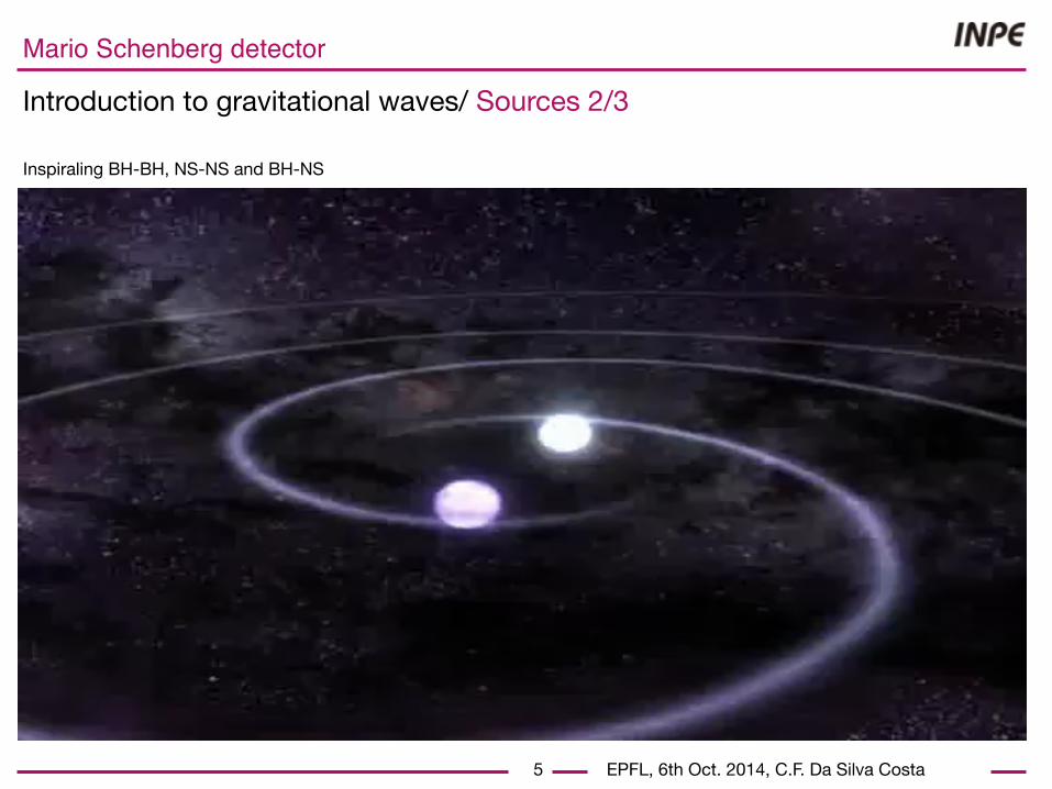
Introduction to gravitational waves/ Sources 2/3
5
Inspiraling BH-BH, NS-NS and BH-NS

EPFL, 6th Oct. 2014, C.F. Da Silva Costa
Mario Schenberg detector
Introduction to gravitational waves/ Sources 2/3
5
Inspiraling BH-BH, NS-NS and BH-NS

EPFL, 6th Oct. 2014, C.F. Da Silva Costa
Mario Schenberg detector
Introduction to gravitational waves/ Sources 2/3
5
Inspiraling BH-BH, NS-NS and BH-NS

EPFL, 6th Oct. 2014, C.F. Da Silva Costa
Mario Schenberg detector
6
Introduction to gravitational waves/ Sources 3/3
Periodic sources (NS)
- fainter than burst ~103 times less.- integrated over long periods (excess in the
frequency spectra).
EPFL, 6th Oct. 2014, C.F. Da Silva Costa
Mario Schenberg detector
7
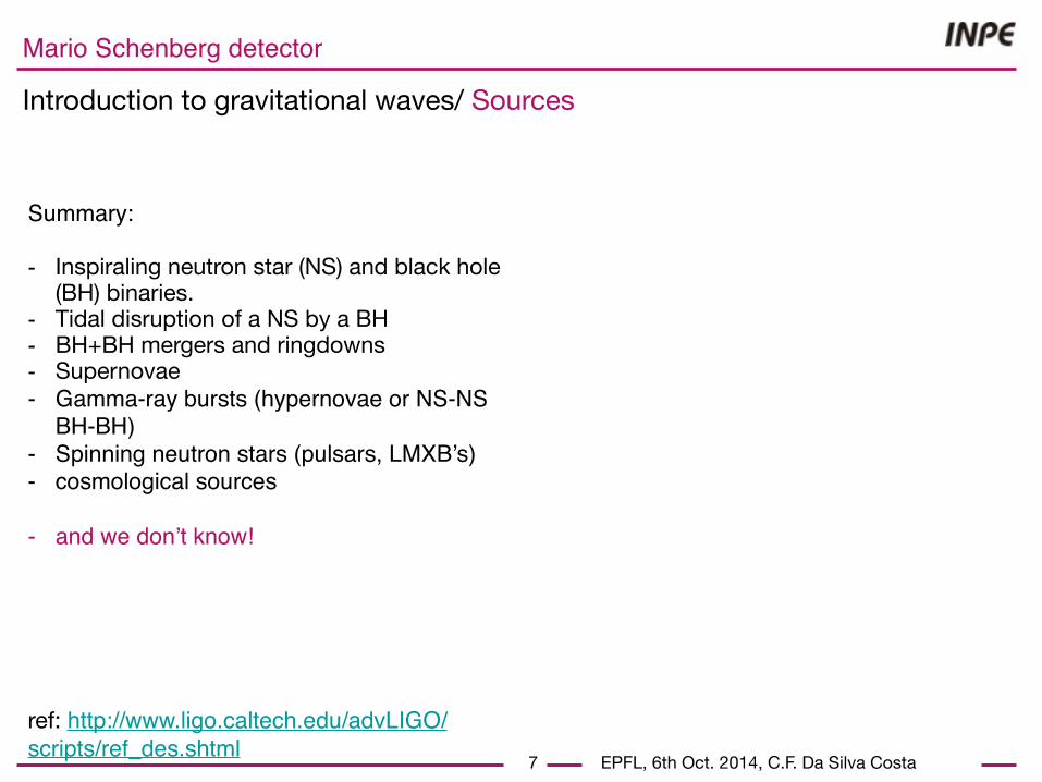
Introduction to gravitational waves/ Sources
Summary:
- Inspiraling neutron star (NS) and black hole (BH) binaries.
- Tidal disruption of a NS by a BH- BH+BH mergers and ringdowns- Supernovae- Gamma-ray bursts (hypernovae or NS-NS
BH-BH) - Spinning neutron stars (pulsars, LMXB’s)- cosmological sources
- and we don’t know!
ref: http://www.ligo.caltech.edu/advLIGO/scripts/ref_des.shtml

EPFL, 6th Oct. 2014, C.F. Da Silva Costa
Mario Schenberg detector
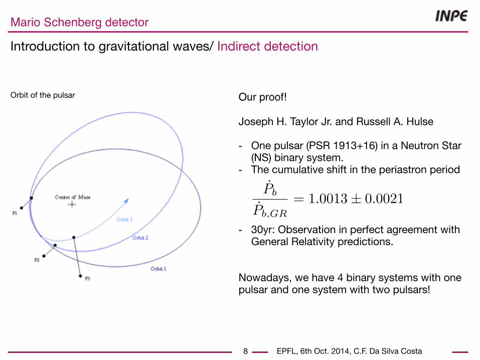
Introduction to gravitational waves/ Indirect detection
8
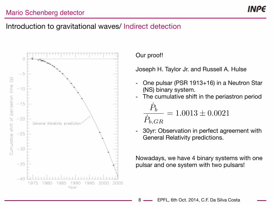
Our proof!
Joseph H. Taylor Jr. and Russell A. Hulse
- One pulsar (PSR 1913+16) in a Neutron Star (NS) binary system.
- The cumulative shift in the periastron period
- 30yr: Observation in perfect agreement with General Relativity predictions.
Nowadays, we have 4 binary systems with one pulsar and one system with two pulsars!
Orbit of a binary system
EPFL, 6th Oct. 2014, C.F. Da Silva Costa
Mario Schenberg detector
Introduction to gravitational waves/ Indirect detection
8
Our proof!
Joseph H. Taylor Jr. and Russell A. Hulse
- One pulsar (PSR 1913+16) in a Neutron Star (NS) binary system.
- The cumulative shift in the periastron period
- 30yr: Observation in perfect agreement with General Relativity predictions.
Nowadays, we have 4 binary systems with one pulsar and one system with two pulsars!
Orbit of the pulsar
EPFL, 6th Oct. 2014, C.F. Da Silva Costa
Mario Schenberg detector
Introduction to gravitational waves/ Indirect detection
8
Our proof!
Joseph H. Taylor Jr. and Russell A. Hulse
- One pulsar (PSR 1913+16) in a Neutron Star (NS) binary system.
- The cumulative shift in the periastron period
- 30yr: Observation in perfect agreement with General Relativity predictions.
Nowadays, we have 4 binary systems with one pulsar and one system with two pulsars!

EPFL, 6th Oct. 2014, C.F. Da Silva Costa
Mario Schenberg detector
Detectors/ Detection principle
9
In the reference frame of the laboratory thedeviation between two geodesics is given by
- in terms of the h matrix
Metric = Minkowski’s metric+perturbation
Wave equation of the metric perturbation

EPFL, 6th Oct. 2014, C.F. Da Silva Costa
Mario Schenberg detector
Detectors/ Detection principle
10
h+
hx
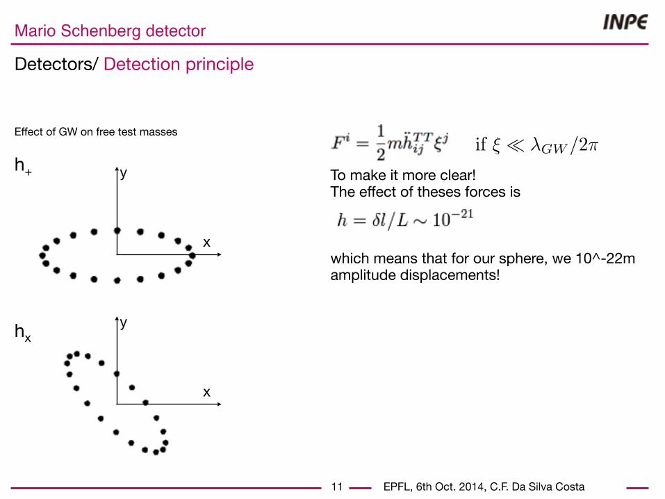
Effect of GW on free test masses
x
x
y
y
- in our laboratory: ~Newtonian force acting on particles (test masses).

EPFL, 6th Oct. 2014, C.F. Da Silva Costa
Mario Schenberg detector
Detectors/ Detection principle
10
h+
hx
Effect of GW on free test masses
x
x
y
y
- in our laboratory: ~Newtonian force acting on particles (test masses).

EPFL, 6th Oct. 2014, C.F. Da Silva Costa
Mario Schenberg detector
Detectors/ Detection principle
11
h+
hx
Effect of GW on free test masses
x
x
y
y
To make it more clear! The effect of theses forces is
which means that for our sphere, we 10^-22m amplitude displacements!
EPFL, 6th Oct. 2014, C.F. Da Silva Costa
Mario Schenberg detector
Detectors/ Detection principle
11
h+
hx
Effect of GW on free test masses
x
x
y
y
To make it more clear! The effect of theses forces is
which means that for our sphere, we 10^-22m amplitude displacements!
EPFL, 6th Oct. 2014, C.F. Da Silva Costa
Mario Schenberg detector
Detectors/ Interferometers
12
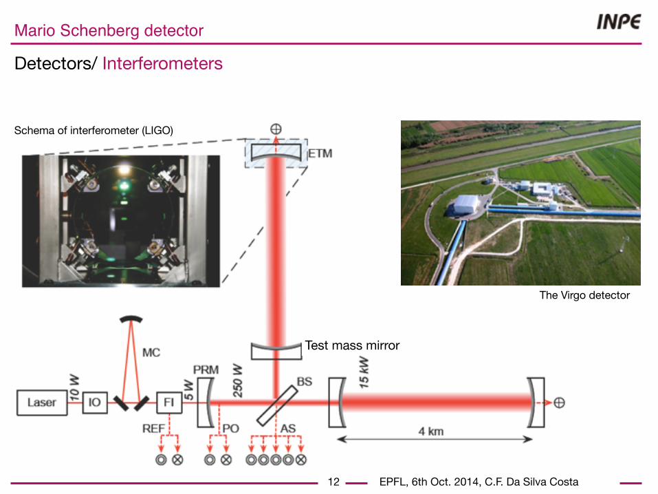
Test mass mirror
Schema of interferometer (LIGO)
The Virgo detector
EPFL, 6th Oct. 2014, C.F. Da Silva Costa
Mario Schenberg detector
Detectors/ Resonant bar
13
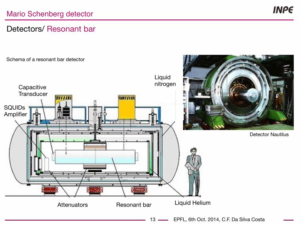
Resonant bar
CapacitiveTransducer
Liquid nitrogen
Schema of a resonant bar detector
Detector Nautilus
Liquid Helium
SQUIDsAmplifier
Attenuators

EPFL, 6th Oct. 2014, C.F. Da Silva Costa
Mario Schenberg detector
Detectors/ Distributions
14
<<
<
<
<
<
<
LIGO Hanford
LIGO Livingston(Alegro)
Virgo Italy
IndigoKAGRA
(AIGO)
Geo600 Germany(Explorer) Switzerland
Nautilus &Auriga Italy
MiniGRAIL Netherland
Mario Schenberg Brazil
EPFL, 6th Oct. 2014, C.F. Da Silva Costa
Mario Schenberg detector
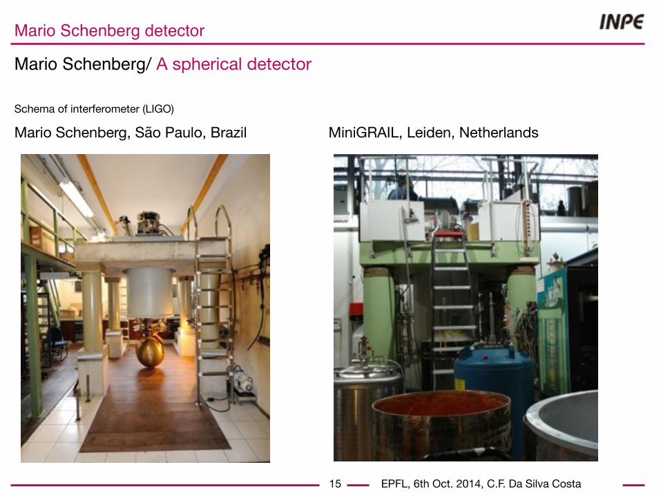
Mario Schenberg/ A spherical detector
15
MiniGRAIL, Leiden, NetherlandsMario Schenberg, São Paulo, BrazilSchema of interferometer (LIGO)
EPFL, 6th Oct. 2014, C.F. Da Silva Costa
Mario Schenberg detector
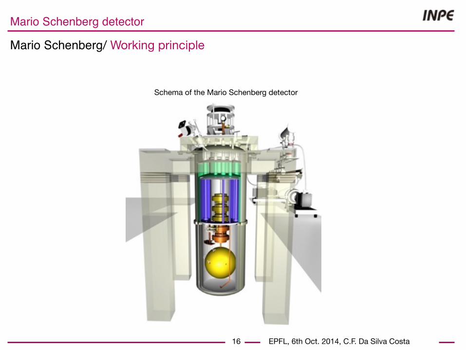
Mario Schenberg/ Working principle
16
Schema of the Mario Schenberg detector

EPFL, 6th Oct. 2014, C.F. Da Silva Costa
Mario Schenberg detector
Mario Schenberg/ Working principle
16
Schema of the Mario Schenberg detector
- weights 1150kg - measures 65cm ∅- high mechanical Q
alloy: CuAl(6%).
EPFL, 6th Oct. 2014, C.F. Da Silva Costa
Mario Schenberg detector
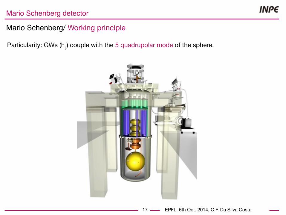
Mario Schenberg/ Working principle
17
Particularity: GWs (hij) couple with the 5 quadrupolar mode of the sphere.

EPFL, 6th Oct. 2014, C.F. Da Silva Costa
Mario Schenberg detector
Mario Schenberg/ Working principle
17
TIGA configuration Six tansducers monitoring Converting transducer oscillations intinto hm
Particularity: GWs (hij) couple with the 5 quadrupolar mode of the sphere.
EPFL, 6th Oct. 2014, C.F. Da Silva Costa
Mario Schenberg detector
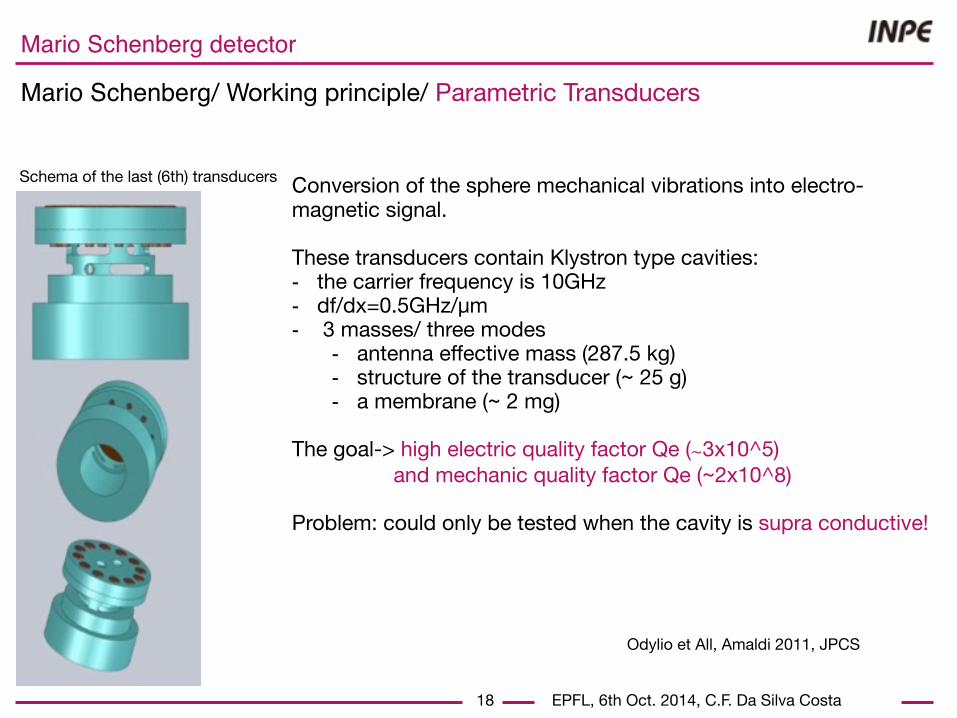
Mario Schenberg/ Working principle/ Parametric Transducers
18
Schema of the last (6th) transducers Conversion of the sphere mechanical vibrations into electro-magnetic signal. These transducers contain Klystron type cavities: - the carrier frequency is 10GHz- df/dx=0.5GHz/µm- 3 masses/ three modes
- antenna effective mass (287.5 kg)- structure of the transducer (~ 25 g)- a membrane (~ 2 mg)
The goal-> high electric quality factor Qe (∼3x10^5) and mechanic quality factor Qe (~2x10^8)
Problem: could only be tested when the cavity is supra conductive!
Odylio et All, Amaldi 2011, JPCS
EPFL, 6th Oct. 2014, C.F. Da Silva Costa
Mario Schenberg detector
Mario Schenberg/ Working principle
19
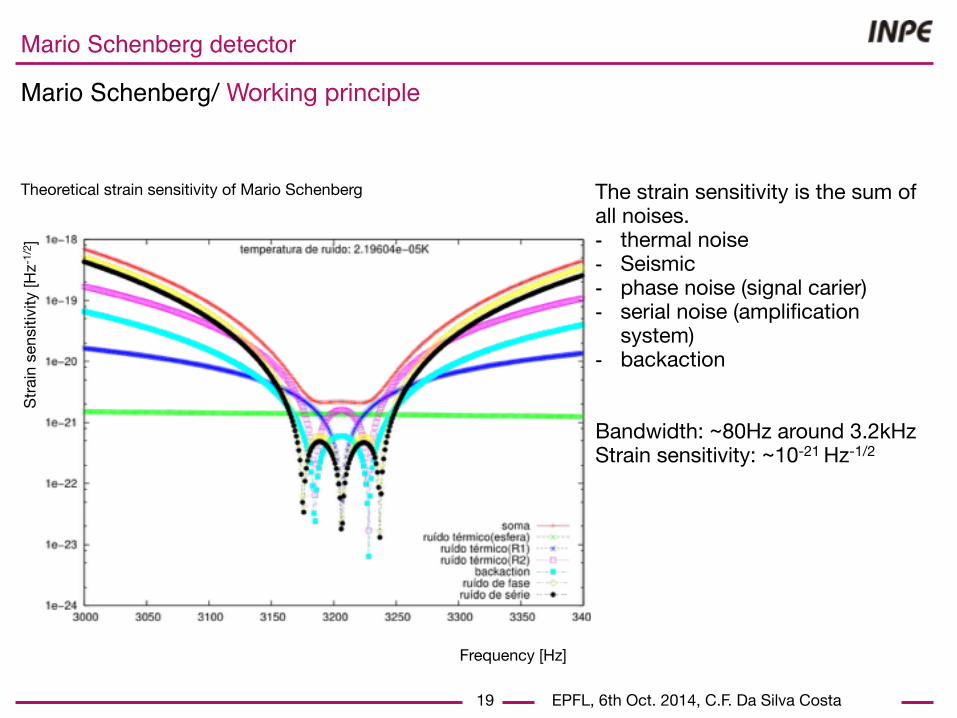
The strain sensitivity is the sum of all noises.- thermal noise- Seismic - phase noise (signal carier)- serial noise (amplification
system)- backaction
Bandwidth: ~80Hz around 3.2kHzStrain sensitivity: ~10-21 Hz-1/2
Frequency [Hz]
Stra
in s
ensit
ivity
[Hz-
1/2 ]
Theoretical strain sensitivity of Mario Schenberg
EPFL, 6th Oct. 2014, C.F. Da Silva Costa
Mario Schenberg detector
Mario Schenberg/ Working principle
20
Schema of the Mario Schenberg detector

EPFL, 6th Oct. 2014, C.F. Da Silva Costa
Mario Schenberg detector
Mario Schenberg/ Working principle
21
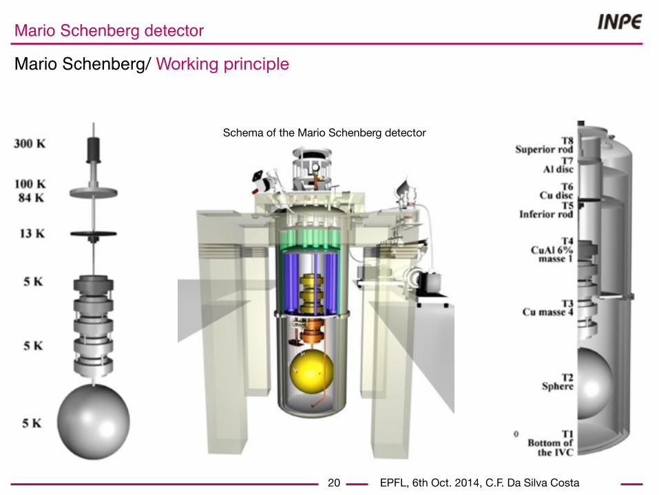
Schema of the Mario Schenberg detector To cancel seismic vibration the detector is equipped with a dumping system.
5 masses act as a pendulum (~130 kg)
Seismic noise attenuation: 320dB
EPFL, 6th Oct. 2014, C.F. Da Silva Costa
Mario Schenberg detector
Mario Schenberg/ Working principle
21
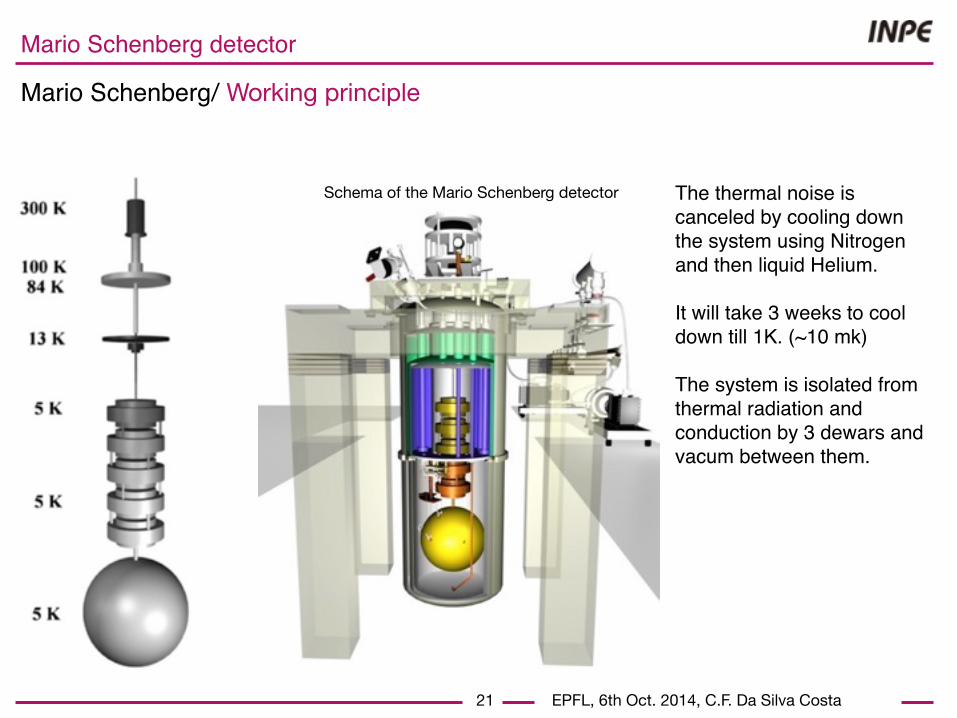
Schema of the Mario Schenberg detector The thermal noise is canceled by cooling down the system using Nitrogen and then liquid Helium.
It will take 3 weeks to cool down till 1K. (~10 mk)
The system is isolated from thermal radiation and conduction by 3 dewars and vacum between them.
EPFL, 6th Oct. 2014, C.F. Da Silva Costa
Mario Schenberg detector
Mario Schenberg/ Next run
22
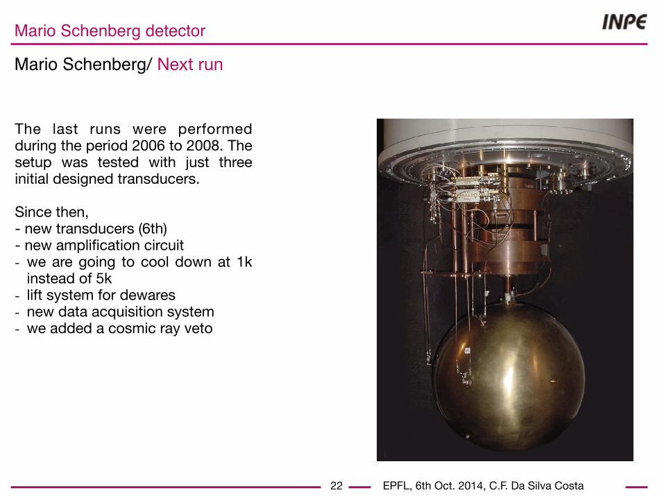
The last runs were performed during the period 2006 to 2008. The setup was tested with just three initial designed transducers.
Since then,- new transducers (6th)- new amplification circuit- we are going to cool down at 1k
instead of 5k- lift system for dewares- new data acquisition system- we added a cosmic ray veto
!

EPFL, 6th Oct. 2014, C.F. Da Silva Costa
Mario Schenberg detector
23
Schema of Amplification signal circuit (as planned) The amplification signal circuit was installed and tested during the last months.
- Sapphire oscillators-> signal carrier 10GHz.- low phase noise- increase frequency stability- synthesizer shift the frequency to the
transducer resonance
!
change to copper
Mario Schenberg/ Next run/ Signal amplification
probe
Later..
EPFL, 6th Oct. 2014, C.F. Da Silva Costa
Mario Schenberg detector
Mario Schenberg/ Next run/ Signal amplification
24
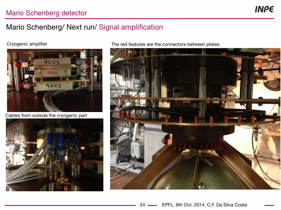
Cryogenic amplifier The red features are the connectors between plates.
Cables from outside the cryogenic part
EPFL, 6th Oct. 2014, C.F. Da Silva Costa
Mario Schenberg detector
Mario Schenberg/ Next run/ Signal amplification
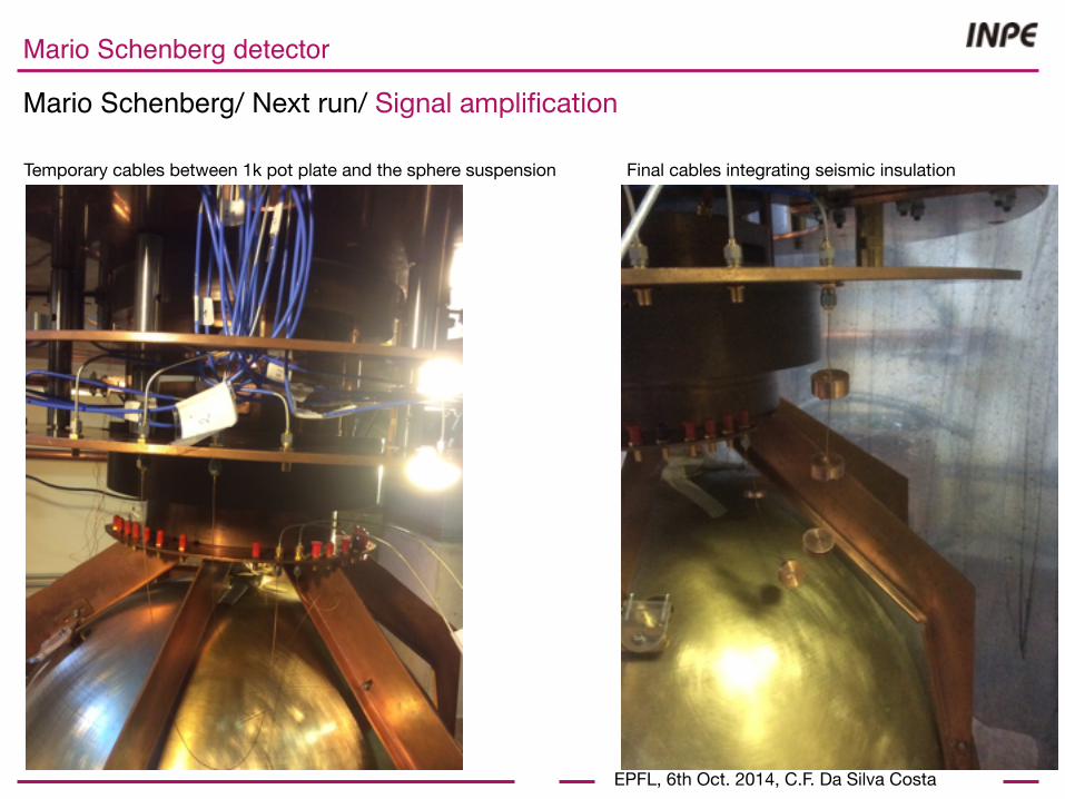
Temporary cables between 1k pot plate and the sphere suspension Final cables integrating seismic insulation
EPFL, 6th Oct. 2014, C.F. Da Silva Costa
Mario Schenberg detector
Mario Schenberg/ Next run/ Signal amplification
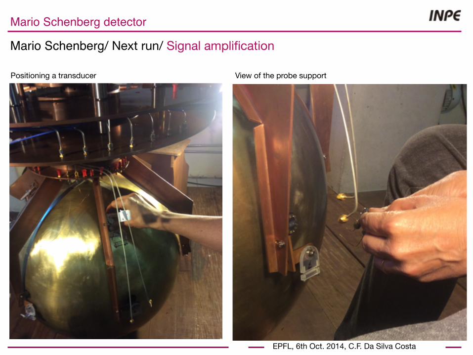
Positioning a transducer View of the probe support

EPFL, 6th Oct. 2014, C.F. Da Silva Costa
Mario Schenberg detector
Mario Schenberg/ Next run/ Signal amplification
Signal generators 10GHz Audio amplifiers for signal of ~3KHz (last stage before DAQ)

EPFL, 6th Oct. 2014, C.F. Da Silva Costa
Mario Schenberg detector
28
Mario Schenberg/ Next run/ DAQ
The Data Acquisition System is composed of:- ADC converter board: VT1436.- GPS receiver for time reference.- PC interface: Agilent plate (VXI->FireWire).
Features:- Sampling 15625Hz- 6 channels- Floats (4bytes) -> amount of data per day: ~30GB reduced to 300MB of data per day
Pictures of the three DAQ boards

EPFL, 6th Oct. 2014, C.F. Da Silva Costa
Mario Schenberg detector
29
Mario Schenberg/ Next run/ DAQ
Preparing cables (TFP->ADC) Testing the DAQ with function generator
coaxial SMB

EPFL, 6th Oct. 2014, C.F. Da Silva Costa
Mario Schenberg detector
Mario Schenberg/ Next run/ DAQ
30
The control room We have installed two PCs:- data acquisition- analysis and sends the data.
Transmission 31.4 ±1,4MB/s. Acquisition rate 1,3MB/s.
This configuration is optimized for low latency analysis.

EPFL, 6th Oct. 2014, C.F. Da Silva Costa
Mario Schenberg detector
Mario Schenberg/ Next run/ DAQ
31
Preparing the control room. Replacing a old server

EPFL, 6th Oct. 2014, C.F. Da Silva Costa
Mario Schenberg detector
Mario Schenberg/ Next run/ Cryogenic
View of the thermal sondes The Pt1000 and Ru02 will monitor many points

EPFL, 6th Oct. 2014, C.F. Da Silva Costa
Mario Schenberg detector
Mario Schenberg/ Next run/ Cryogenic
View of the thermal sondes The Pt1000 and Ru02 will monitor many points

EPFL, 6th Oct. 2014, C.F. Da Silva Costa
Mario Schenberg detector
Mario Schenberg/ Next run/ Cryogenic
View of the dewars with the floor open Testing the system to lift the 3 dewars

EPFL, 6th Oct. 2014, C.F. Da Silva Costa
Mario Schenberg detector
Mario Schenberg/ Next run/ Cryogenic
Testing the system to lift the 3 dewarsTesting the system to lift the 3 dewars
EPFL, 6th Oct. 2014, C.F. Da Silva Costa
Mario Schenberg detector
Mario Schenberg/ Next run/ Cosmic rays veto
35
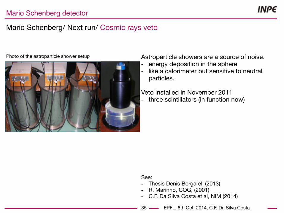
Photo of the astroparticle shower setup Astroparticle showers are a source of noise.- energy deposition in the sphere - like a calorimeter but sensitive to neutral
particles.
Veto installed in November 2011- three scintillators (in function now)
See: - Thesis Denis Borgareli (2013)- R. Marinho, CQG, (2001)- C.F. Da Silva Costa et al, NIM (2014)

EPFL, 6th Oct. 2014, C.F. Da Silva Costa
Mario Schenberg detector
Mario Schenberg/ Next run/ Cosmic rays veto
36
Photo of the DAQ of the cosmic ray veto During the next run, the 3 scintillators will be placed below the sphere. - > coincidences between event in the sphere a cosmic ray showers.

EPFL, 6th Oct. 2014, C.F. Da Silva Costa
Mario Schenberg detector
Mario Schenberg/ Future/ What we expect?
37
In a close future,- 3 weeks cooling- the setup works or not?- continue to develop the
detector, corrections and adjustments
We do not expect any detection. - not competitive(Bandwidth: ~80Hz around 3.2kHz, Strain sensitivity: ~10-21
Hz-1/2)
S Hild, Class. Quantum Grav. 29 (2012) 124006 (9pp)
Schenber

EPFL, 6th Oct. 2014, C.F. Da Silva Costa
Mario Schenberg detector
Mario Schenberg/ Future/ What we expect?
38
Future (2016-2020),But we hope that aLIGO will do detect something.
Advanced LIGO–Virgo network: ~40 events per year (0.4 and 400 per year)
Ligo, Class. Quantum Grav. 27 (2010) 173001 (25pp).
S Hild, Class. Quantum Grav. 29 (2012) 124006 (9pp)
Schenber

EPFL, 6th Oct. 2014, C.F. Da Silva Costa
Mario Schenberg detector
Mario Schenberg/ Future/ Let’s do what we know best!
39
We are better for fast GW source localization!
The main advantages:- Six detectors in one!- The sphere is isotropic.- We have the GW arrival direction and polarisation.
-> A sphere is well designed for GW astronomy.
As soon as one detection is confirmed, the Schenberg detector technology will interest small groups.It’s like small telescopes available for universities, when aLigo and aVirgo are Hubble telescopes.
z x
y
(θ,φ) GW direction

EPFL, 6th Oct. 2014, C.F. Da Silva Costa
Mario Schenberg detector
40
Mario Schenberg/ Future /New Low latency
Multi-messenger analysis:- confront possible GW with other
astrophysical messengers X,γ,ν etc- GW direction in few second with a good
confidence.
We are improving our pipeline (CUDA, more sophisticate filters).
Event messenger accompanying GW emissions
EPFL, 6th Oct. 2014, C.F. Da Silva Costa
Mario Schenberg detector
41
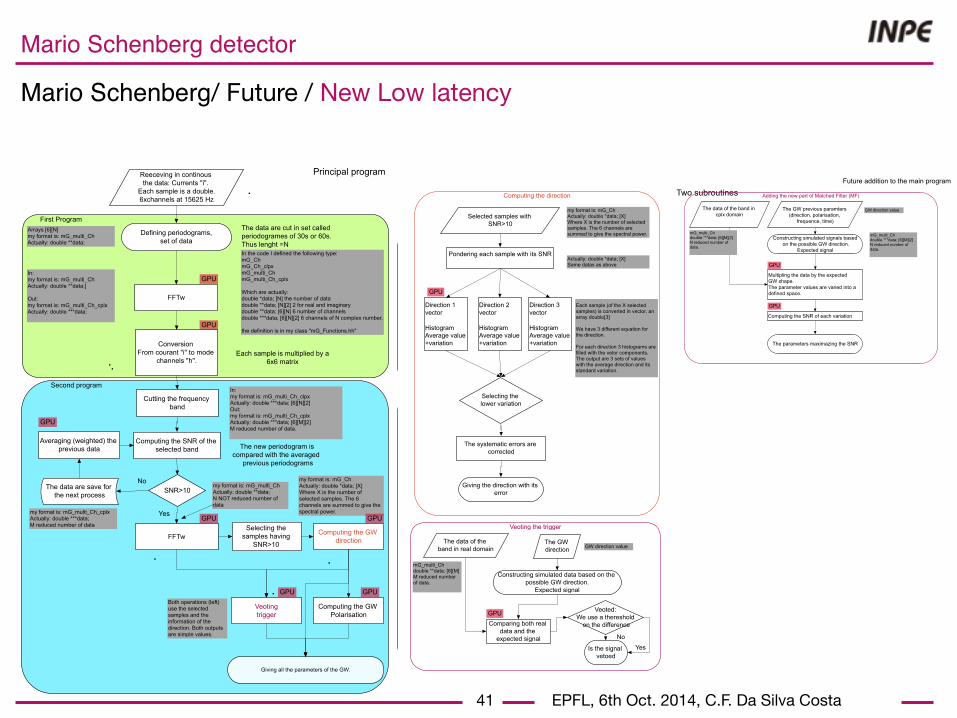
Mario Schenberg/ Future / New Low latency
Second program
First Program
Defining periodograms, set of data
Conversion From courant "i" to mode
channels "h".
SNR>10No
Yes
The data are cut in set called periodogrames of 30s or 60s. Thus lenght =N
Cutting the frequency band
Each sample is multiplied by a 6x6 matrix
Averaging (weighted) the previous data The new periodogram is
compared with the averaged previous periodograms
Computing the SNR of the selected band
Reeceving in continous the data: Currents "i".
Each sample is a double. 6xchannels at 15625 Hz
The data are save for the next process
Selecting the samples having
SNR>10
Computing the GW direction
Arrays [6][N] my format is: mG_multi_Ch Actually: double **data;
FFTw
In: my format is: mG_multi_Ch Actually: double **data;] Out: my format is: mG_multi_Ch_cplx Actually: double ***data;
In the code I defined the following type: mG_Ch mG_Ch_clpx mG_multi_Ch mG_multi_Ch_cplx Which are actually: double *data; [N] the number of data double **data; [N][2] 2 for real and imaginary double **data; [6][N] 6 number of channels double ***data; [6][N][2] 6 channels of N complex number. the definition is in my class "mG_Functions.hh"
FFTw
my format is: mG_multi_Ch_cplx Actually: double ***data; M reduced number of data
In: my format is: mG_multi_Ch_clpx Actually: double ***data; [6][N][2] Out: my format is: mG_multi_Ch_cplx Actually: double ***data; [6][M][2] M reduced number of data.
my format is: mG_multi_Ch Actually: double **data; N NOT reduced number of data
Computing the GW Polarisation
Veoting trigger
my format is: mG_Ch Actually: double *data; [X] Where X is the number of selected samples. The 6 channels are summed to give the spectral power.
Both operations (left) use the selected samples and the information of the direction. Both outputs are simple values.
Giving all the parameters of the GW.
GPU
GPU
GPU
GPU
GPU GPU
GPU
Principal program
Second program
First Program
Direction 1 vector Histogram Average value +variation
Direction 3 vector Histogram Average value +variation
Direction 2 vector Histogram Average value +variation
Selected samples with SNR>10
Pondering each sample with its SNR
Selecting the lower variation
Computing the direction
Giving the direction with its error
my format is: mG_Ch Actually: double *data; [X] Where X is the number of selected samples. The 6 channels are summed to give the spectral power.
Actually: double *data; [X] Same datas as above
Each sample (of the X selected samples) is converted in vector, an array double[3] We have 3 different equation for the direction. For each direction 3 histograms are filled with the vetor components. The output are 3 sets of values with the average direction and its standard variation.
The systematic errors are corrected
GPU
Veoting the trigger
The data of the band in real domain
The GW direction
Constructing simulated data based on the possible GW direction.
Expected signal
Comparing both real data and the
expected signalIs the signal
vetoed
mG_multi_Ch double **data; [6][M] M reduced number of data.
GW direction value
Veoted: We use a thereshold
on the difference
No
Yes
GPU
Principal program Two subroutines Adding the new part of Matched Filter (MF)
The data of the band in cplx domain
The GW previous paramters (direction, polarisation,
frequence, time)
Constructing simulated signals based on the possible GW direction.
Expected signal
Multipling the data by the expected GW shape. The parameter values are varied into a defined space.
mG_multi_Ch double ***data; [6][M][2] N reduced number of data.
GW direction value
mG_multi_Ch double ***data; [6][M][2] N reduced number of data.
Computing the SNR of each variation
The parameters maximazing the SNR
GPU
GPU
Two subroutines Future addition to the main program

EPFL, 6th Oct. 2014, C.F. Da Silva Costa
Mario Schenberg detector
42
Mario Schenberg/ Future / Transducers
Study of feasibility of a nanogap transducer is projected -> larger bandwidth
The goal is 1nm (bandwidth from 50Hz to 1 kHz)!
sapphire40 mm diameter30 mm hight
0 2000 4000 6000 8000 10 00010!24
10!22
10!20
10!18
Frequency !Hz"
StrainNoiseSpectralDensityh"#1 H
z
$
EPFL, 6th Oct. 2014, C.F. Da Silva Costa
Mario Schenberg detector
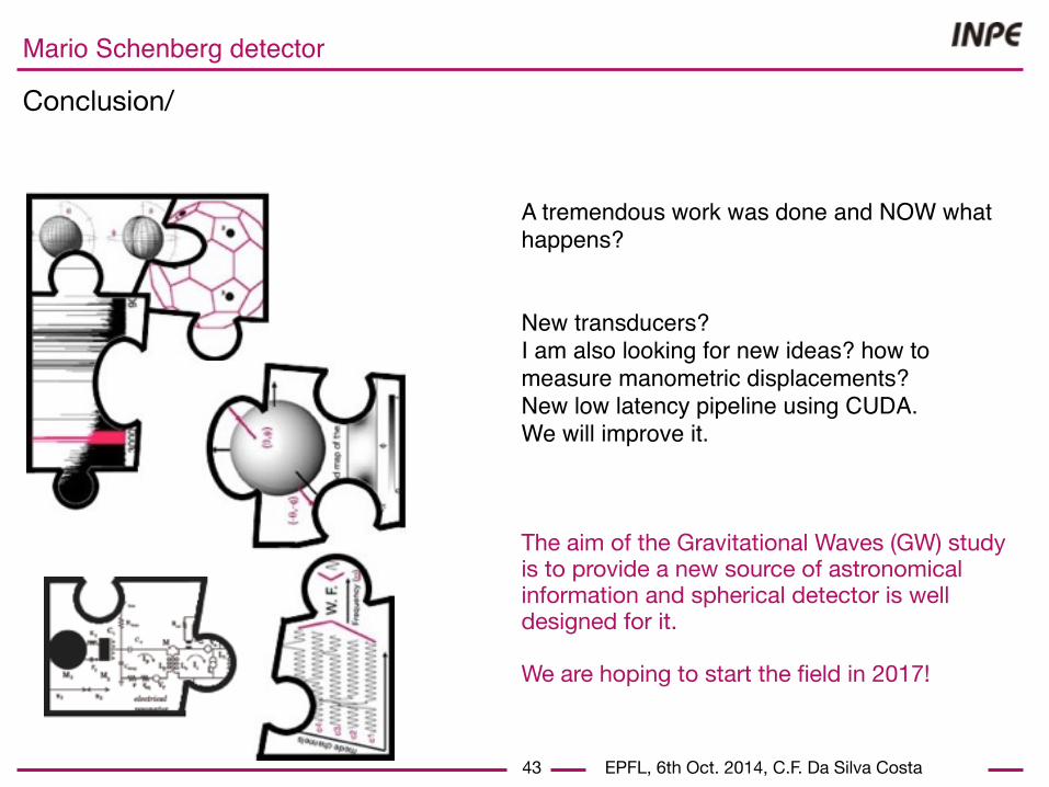
Conclusion/
43
A tremendous work was done and NOW what happens?
New transducers? I am also looking for new ideas? how to measure manometric displacements? New low latency pipeline using CUDA.We will improve it.
The aim of the Gravitational Waves (GW) study is to provide a new source of astronomical information and spherical detector is well designed for it.
We are hoping to start the field in 2017!
EPFL, 6th Oct. 2014, C.F. Da Silva Costa
Mario Schenberg detector
Presentation/ End
44
??
?

EPFL, 6th Oct. 2014, C.F. Da Silva Costa
Mario Schenberg detector
Presentation/ End
44
??
?