THE GUIDE TO CERAMIC CHIMNEY SYSTEMS AND LINERS
32
THE GUIDE TO CERAMIC CHIMNEY SYSTEMS AND LINERS ENABLING ENERGY EFFICIENCY DOC/CP3/65 Issue 2 June 2015 Part of the BRAAS MONIER BUILDING GROUP
Transcript of THE GUIDE TO CERAMIC CHIMNEY SYSTEMS AND LINERS

THE GUIDE TO CERAMIC CHIMNEY SYSTEMS AND LINERS
ENABLING ENERGYEFFICIENCY
DOC/CP3/65 Issue 2 June 2015 Part of the BRAAS MONIER BUILDING GROUP

2
The Schiedel C eramic RangeIn order to meet the new European Standards for Chimney products, specific leakage and performance criteria have to be met, which are much more stringent than in the past.Schiedel have invested in the latest production technology and are proud to introduce a new range of high performance rebated ceramic flue liners, which are fully CE tested and approved and are fully compatible with the increasingly efficient modern appliances, as well as meeting the more traditional soot fire requirements.These liners are now used throughout the Schiedel range of standard ceramic chimney products, which consists of:-Ceramic Chimney LinersSwift - System ChimneySwift Air - System Chimney for room sealed appliancesSchiedel has sourced the finest raw materials, blended in a unique formula to give a unique combination of temperature resistance and strength.
Resistant to Thermal ShockThe liners are extremely durable and have been tested for resistance to soot fire as well as to condensate, and meet the latest CE standards and Construction Products Regulations (CPR).
LightweightDue to advanced manufacturing techniques, we have been able to reduce the wall thickness of the liner to produce the optimal lightweight but extremely robust product.
Smooth Inner WallThe smooth inner liner allows gas, the product of combustion to freely exit the chimney. Straight lines ensure a consistent fill of insulation.
The natural properties of ceramic
SCHIEDELSWIFTSchiedel Swift is a high quality modular System Chimney comprising of 3 layers. An outer block stone, an insulation wrap and a ceramic liner, CE approved for use on both high temperature and low temperature applications. The system can be installed internally or externally and is ideal for new Build applications.
SCHIEDELSWIFT AIRSchiedel Swift Air is a 3 layer Modular System Chimney with a built in channel for ventilation, which allows the system to be used with room sealed appliances, bringing the combustion air to the appliance from roof level, ensuring the right volume of combustion air is available to the appliance. This system is ideal for use in Energy efficient A rated New Build Homes.
CERAMIC FLUE LINERSThe Schiedel range of Ceramic Flue Liners has been tested and approved to meet the latest European Standards and Construction Product Regulations (CPR) for both High Temperature and Low Temperature applications.
CHIMNEY POTS & ACCESSORIESSchiedel Chimney Pots and accessories are designed to bring simple, aesthetic solutions to the Chimney design, both within the fireplace and through to termination, with a range of styles to suit all homes.
Product DescriptionThe Schiedel Ceramic Product Range consists of Chimney liners for the refurbishment of existing chimneys as well as System Chimneys for New Build Applications and System Chimneys with a built in ventilation channel for use in room sealed applications on energy efficient houses.

3
Rapid
Ceramic Flue Liners - Traditional Build
Joint Detail
In order to meet the new European Standards for Chimney products, specific leakage and performance criteria have to be met, which are much more stringent than in the past.
Schiedel have invested in the latest production technology and are proud to introduce a new range of high performance rebated ceramic flue liners, which are fully CE tested and approved and are fully compatible with the increasingly efficient modern appliances, as well as meeting the more traditional soot fire requirements.
This new generation of rebated ceramic chimney liners is available as standard in the following diameter range:-160mm, 180mm, 200mm, 250mm, 300mm.
Direction of flue gases
Liners are installed with the male spigot pointing downwards. Schiedel Rapid HT Cement should be applied to the inside of the female socket and any excess projecting into the flue should be wiped off as installation progresses.
RAPID HT CEMENT USAGE
Usage of Rapid HT Cement & Leca InsulationLECA INSULATION REQUIREMENT FOR BACKFILL
Int Ø (mm)
160160160180180180200200200250250250300300300
ExtØ (mm)
190190190210210210230230230290290290340340340
Chimney Void (mm)
235 x 235235 x 350350 x 350235 x 235235 x 350350 x 350350 x 350350 x 460460 x 460350 x 350350 x 460460 x 460460 x 460460 x 575575 x 575
Chimney Void (inches)
9” x 9”9” x 14”14” x 14”9” x 9”9” x 14”14” x 14”14” x 14”14” x 18”18” x 18”14” x 14”14” x 18”18” x 18”18” x 18”18” x 23”23” x 23”
Bags per linear metre
0.481.021.821.081.622.422.152.494.201.171.942.962.603.755.25
Int Ø (mm)
160
180
200
250
300
No. Jointsper tube
9
7
6
5
3
Schiedel Ceramic Liners are CE Certified to EN 1457-1 & 2 TÜV 0780 CPD 131086 with the following designations:
Approvals
High Temperature Applications Low Temperature Applications
EN 1457-1A1 N1 (T600 N1 G)
EN 1457-2B4 N1 (T400 N1 WC O)
D4 N1 (T200 N1 WC O)*
* When used on T200 rated low temperature systems, the liner system should be straight and fully ventilated.
Male Spigot
Female Socket

4
Ceramic Flue Liners - ComponentsOld Code SAP Code Description Weight (kg)All dimensions are external apart from the liner diameters, which are internal.
Rebated LinerA03 100374 330mm high 160mm Ø 5.6- 100375 330mm high 180mm Ø 6.3A05 100376 330mm high 200mm Ø 7.1A07 100310 330mm high 250mm Ø 15.3A08 100311 330mm high 300mm Ø 17.6
Rebated LinerA03 100374 330mm high 160mm Ø 5.6- 100375 330mm high 180mm Ø 6.3A05 100376 330mm high 200mm Ø 7.1A07 100310 330mm high 250mm Ø 15.3A08 100311 330mm high 300mm Ø 17.6
90˚ Tee- 100420 660mm high 160mm Ø 13.3- 100421 660mm high 180mm Ø 14.5- 100422 660mm high 200mm Ø 15.4
Inspection Pipe/Inner Soot Door- 100428 660mm high 160mm Ø 13.6- 100429 660mm high 180mm Ø 14.9- 100430 660mm high 200mm Ø 16.7
45˚ Tee- 100424 660mm high 160mm Ø 15.9- 100425 660mm high 180mm Ø 18.1- 100426 660mm high 200mm Ø 19.1
Outer Soot Door- 100475 160mm Ø 10- 100475 180mm Ø 10- 100475 200mm Ø 10
FirebackFDFB16 130748 Concrete 400mm 15FDFB18 130749 Concrete 450mm 15
45˚ Bend- 131622 60mm Ø 5.6- 131623 180mm Ø 6.3- 131624 200mm Ø 7.1
Base Stone with Drain- 102684 170mm high 160mm Ø 12- 102685 170mm high 180mm Ø 14- 102686 170mm high 200mm Ø 16
37.5˚ BendB03 121334 160mm Ø 8.3- 121335 180mm Ø 9B10 121336 200mm Ø 10.5B18 121337 250mm Ø 17.9B12 121338 300mm Ø 17.9

5
Ceramic Flue Liners - ComponentsOld Code SAP Code Description Weight (kg)All dimensions are external apart from the liner diameters, which are internal.
Rapid
Fire GatherC15 130698 200mm Ø 110C16 130699 225mm Ø 110C17 131200 250mm Ø 130C18 131201 300mm Ø 130
Coping- 130703 550 x 550mm Ø rendered stack 38- 131196 760 x 760mm Ø brick stack 62
Coping PF- 130700 630 x 530mm Ø rendered stack 52- 131197 790 x 800mm Ø brick stack 101
Notice Plate- 130696 Chimney Notice Plate -
LecaA50301 130769 Leca Backfill Insulation (50 litre) 19
Schiedel RapidA17500100 100020 Rapid HT Cement (310ml) -
Adaptor from Steel to Ceramic Liner- 132667 160mm Ø 1.5- 132668 180mm Ø 1.5- 132669 200mm Ø 2
Collars- COA 160mm Ø -- COA 180mm Ø -- COA 200mm Ø -- COA 250mm Ø -- COA 300mm Ø -
Lintel HeadA1700003 130770 Lintel Head 1500 x 150mm 75mm high 36
Used in pairs to support the weight of the support block as an alternative to a cast slab. On a clear span of up to 1.2m a load of up to 5kN can be supported.
Roll Top Pots1 129041 300mm high Buff 101 129042 300mm high Terracotta 101 129040 300mm high Black 10
Refer to pages 28 - 29 for full range of pots and terminals
Stove Starter BlockA1800038 131183 360 x 360 x 100mm high 160mm Ø 18A1800039 131184 360 x 360 x 100mm high 180mm Ø 18A1800040 131185 360 x 360 x 100mm high 200mm Ø 18
COA: code on application
6
BUILDING REGULATIONSThe construction and application of chimneys and flues is covered by Building Regulations in conjunction with the relevant European Standards. Whilst these differ in emphasis, they all mandate the safe application of the chimney no matter where and how used. These Regulations and Standards dictate the minimum criteria which it is necessary to apply if the chimney or flue is to function safely and correctly.
Building control approval is necessary for building new chimneys and in some cases for relining old chimneys particularly if some alteration or change of the heating appliance occurs. The appropriate Regulations and Standards are listed below.
England & Wales: Building Regulations Approved Document J
Scotland: Building Regulations Technical Standards
Northern Ireland: Building Regulations Technical Booklet L
Republic of Ireland:Building Regulations Technical Guidance Document J
FLUE SIZINGIt is important to match the internal diameter of the flue with the outlet on the appliance. It should never be less than the outlet diameter of the appliance. The appliance manufacturer’s chimney sizing recommendations should always be followed.
For open fires with a standard fire opening up to 500mm wide by 550mm high the minimum required flue diameter is 200mm round. For larger open fires, such as inglenooks, dog grate installations or special appliances and stoves designed to operate with a fire opening greater than 500mm x 550mm, the flue size should be at least 15% of the free unobstructed area of the fire opening (including sides if open). Many Decorative Fuel Effect gas fires (DFE’s) that imitate a coal or log burning open fire require the same chimney arrangement as for solid fuel open fires and must be installed in accordance with respective local building regulations
OPEN FIRE OPTIONConstruction begins by providing a suitable foundation and constructional hearth in accordance with local Building Regulations and site requirements.
Form the fire opening onto the constructional hearth. 100mm of brick or blockwork must be built around the sides and back of the firechest to comply with Building Regulations.
RECESSED STOVE OPTIONA suitable cast-in-situ concrete slab lintel must be provided above the fireplace recess. Alternatively you could use suitable pre stressed lintels, for this method a support plate is required under the support block. It is recommended to have a minimum of 600mm length of flue pipe before connecting to the chimney.
Apply Schiedel Rapid HT Cement onto a suitably formed fire gather. Position the flue liner onto the prefabricated gather, female rebate facing upwards. Arrows on each flue liner indicate the directional flow of flue gases. Continue to apply Schiedel Rapid HT Cement to each flue liner, cleaning any access material from the joints.
The support block is bedded onto the slab lintel using weak mix mortar. A stainless steel adaptor or a section of Prima Smooth connecting flue pipe is used to connect from the support block to the stove flue pipe. This adaptor is pushed up onto the support block spigot (fibre rope should be used to create a seal).
Ceramic Flue Liners - Installation Guidelines
OPEN FIRE OPTION
Leca
Leca
Fire Back
Round Liner
Round Bend
Gather Lintel

7
FREE STANDING STOVE OPTIONA soot door must be provided below the flue pipe entry to allow for inspection and removal of soot and debris. A suitable wall sleeve is to be used to seal the cavity wall. Any combustible insulation within the wall must be kept away from the single skin connecting flue pipe by at least 1.5 x its diameter. (Example: diameter 150mm x 1.5 = 225mm distance).
The flue pipe is a push fit over the spigot on the adaptor. Seal off the gap between the flue pipe and wall sleeve with fire proof rope and closing plate.
Ceramic Flue Liners - Installation Guidelines
Support block for stove connection
Joints sealed with Schiedel Rapid HT Cement
Standard flue liners
Void filled with Leca insulation mix
Pre-stressed lintels or cast in situ slab
RECESSED STOVE OPTION
FREE STANDING STOVE OPTION
45˚ Tee liner
Wall SleeveTrim Collar
Soot Door
Base Stone with Drain
Inspection Pipe
Tee Liner and Steel Adaptor
Prima Smooth Connecting Flue Pipe
ALL OPTIONSApply Schiedel HT Cement onto the male rebate of the flue liner. (refer to table on page 3)
Position the flue liner on a suitably formed fire gather or support block with the female rebate facing upwards. Arrows on each flue liner indicate the directional flow of flue gases. Continue to apply high temperature cement to each flue liner, cleaning any access material from the joints.
RapidRapid
Rapid
Joints sealed with lip glue
Leca insulation
Joints sealed with Schiedel Rapid HT Cement
Clad the flue liners with a minimum of 100mm suitable masonry. A minimum of 15mm Leca insulation must be installed between the flue liners and masonry. Mix 20 parts Leca to 1 Part cement and a small amount of water. Ensure it is well mixed before using. (refer to table on page 3)

8
AFTER COMPLETIONAfter installation is complete tests and checks should be carried out in accordance with local Building Regulations. A chimney notice plate must be completed and permanently fixed in the dwelling, ideally near the electrical consumer unit. The checklist and notice plate are available from Schiedel.
USE AND MAINTENANCEThe chimney should be swept at least twice a year, once before the heating season and once after the heating season. You may need to sweep during the heating season depending upon use.
Always follow the appliance manufacturer’s operating instructions. Always burn approved fuels or dry seasoned wood. Avoid burning unseasoned wood and slow burning of solid fuels as this can produce excessive soot and condensation which can in turn cause soot fires and damage. If correctly installed, operated and maintained these systems should last the life of the dwelling.
Flaunching
Weep holes above tray
Lead tray and flashing
Liner or chimney pot
If Bends are required in the chimney make sure adequate support is provided and always backfill with leca insulation mix. Liners can be cut between bends to achieve a required offset distance. A steel collar as well as high temperature cement must be used for any cut joints. A maximum of 2 complete offsets (4 bends) are allowed per chimney and the angle must not be greater than 45˚ from the vertical.
Fit appropriate lead dpc’s and flashings in accordance with the relevant regulations. It is recommend that the lead tray should be dressed up the outside of the flue liners to avoid a weak joint. Weep holes should be provided above the tray for moisture drainage.
Terminate the chimney to the correct height in accordance with local Building Regulations. The chimney can be finished by flaunching (1:3 cement/sharp sand) around a suitable chimney pot. Approved rain caps can be used to help prevent water entering the flue.
Ceramic Flue Liners - Installation Guidelines
OFFSET WITH 2 BENDS OFFSET WITH 2 BENDS & LINER
Total Offset
VerticalHeight
Diameter (mm)
160160180180200200250250
TotalHeight
545779545779545779553794
TotalOffset
222455226460226460233461
Bends45˚
2 2222222
Length330mm
01010101
Diameter (mm)
160160180180200200250250
TotalHeight
580842569830568830569814
TotalOffset
197398193394190392209425
Bends37.5˚
2 2222222
Length330mm
01010101
You must provide adequate clearance from combustible material in accordance with local Building Regulations. Combustible materials must be 200mm from the inner surface of flue liner or 40mm from the outside of the masonry chimney unless it is a floorboard, skirting board, dado or picture rail, mantel-shelf or architrave.
SUPPORTING AN OFFSETThe bends and liners that make up an offset must be supported adequately
Diameter (mm)
160160180180200200250250300300
TotalHeight
596880600888596881559839610892
TotalOffset
155320161326160325157318164326
Bends30˚
2 222222222
Length330mm
0101010101
VerticalHeight
Total Offset

9
The Schiedel Swift Chimney System ConceptThe Schiedel Swift Chimney System is a ceramic chimney system designed in modular units which can be quickly assembled on site, significantly reducing the chimney construction time. The chimney system can be adapted to suit all types of appliances including open fires, multi-fuel stoves, boilers and other bespoke applications.
The concept involves amodular 3 layer insulatedchimney system:
1st LAYERA high quality flue liner, made of fireclay, tested to EN1457.
2nd LAYERA flexible insulation board designed to maintain the temperature of the flue gases and allow them to pass freely up the chimney. It also allows the flue liner to expand and contract without damage.
3rd LAYERA lightweight chimney block which safely encases the whole system and provides additional insulation.
Key FeaturesDesigned for speed of construction
Suitable for Timber Frame, Steel Frame and Masonry construction. Solutions have been specifically designed to meet the requirement of timber framed construction.
Modular units for easy assembly on site.
Suitable for all fuels - gas, oil, solid fuels and biomass.
Schiedel Rapid HT Cement is provided in tubes for ease of application.
Superior Insulation - The consistency of the insulation maintains the temperature of the flue gases allowing them to pass freely up the chimney. Back filling of insulation is not required.
The use of a chimney tray is always recommended.
The high quality fireclay flue liner complies with the European Standard EN1457-1 & 2
10
Schiedel Swift - Open Fires
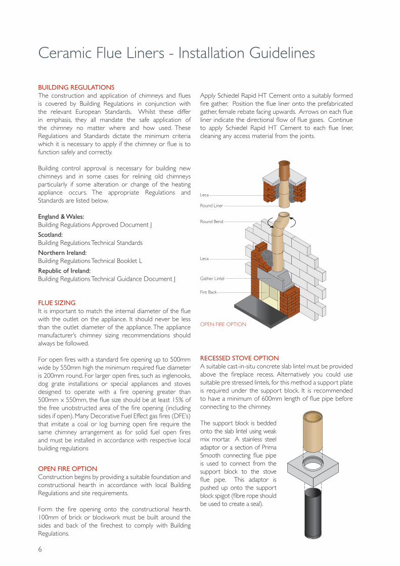
INTERNAL OPEN FIRE(Timber frame, steel frame and masonry construction)Single chimney for timber frame, steel frame or masonry constructions. Available with a corbel for 3 brick wide (675mm) brick or rendered stack, or as a Plain Swift without the corbel stack (360mm square). Strengthening bars only required if chimney is taller than 1.2m.
BEND & OFFSETSIt is recommended that a chimney be constructed as a straight chimney. Were a bend is required, for example to move the chimney into a corner in the first floor, a Schiedel Swift bend kit can be used.
The Breast Bend The breast bend kit will allow the flue to be offset to variable lengths, subject to the diameter beingused. (See offset chart page 8)
The Roof Space Offset Kit A combination of both Schiedel Swift and Schiedel Twin wall stainless steel flue allows an offset in the roof space without the need for constructional support.
EXTERNAL OPEN FIRE / FREE STANDING STOVESuitable for a single chimney where the chimney is on the outside of the building. A bend kit can be used to offset the chimney to one side.
230
480
580
810

11
Schiedel Swift - Stoves & Boilers
INTERNAL RECESSED STOVEChimney system to suit oil burning and solid fuel stoves.
FREE STANDING STOVE
BOILERSChimney system for gas, oil and biomass boilers.
The Schiedel Swift is also an ideal solution for stoves, cookers and central heating boilers. Neat and simple solutions suit a variety of installations.These options offer all the benefits of the Open Fire solutions with tailor made components to simplify construction. The accessories on the stoves, cookers and boiler systems include preformed junction pipes and inspection doors for ease of maintenance. For stoves, cookers and boilers the system is available in 160mm, 180mm and 200mm internal flue diameters.

12
Schiedel Swift - Components
Chimney Block (incl Liner & Insulation) - COA 360 x 360 x 325mm high 160mm Ø 29- COA 360 x 360 x 325mm high 180mm Ø 30- COA 360 x 360 x 325mm high 200mm Ø 31
Chimney Block A101003636 100353 360 x 360 x 325mm high 160mm Ø 23A101003636 100353 360 x 360 x 325mm high 180mm Ø 23A101003636 100353 360 x 360 x 325mm high 200mm Ø 23
InsulationA160100015 133296 1 Per Chimney Block 160mm Ø 0.5A160100018 100379 2 Per Chimney Block 180mm Ø 0.3A000505008 100380 2 Per Chimney Block 200mm Ø 0.3
Rebated LinerA03 100374 333mm high 160mm Ø 6A04 100375 333mm high 180mm Ø 6A05 100376 333mm high 200mm Ø 7
Bend Kit- COA 160mm Ø 58- COA 180mm Ø 60- COA 200mm Ø 62
Old Code SAP Code Description Weight (kg)All dimensions are external apart from the liner diameters, which are internal.
FirebackFDFB16 130748 Concrete 400mm 15FDFB18 130749 Concrete 450mm 15
90˚ Tee- 100420 660mm high 160mm Ø 13.3- 100421 660mm high 180mm Ø 14.5- 100422 660mm high 200mm Ø 15.4
Inspection Pipe/Inner Soot Door- 100428 660mm high 160mm Ø 13.6- 100429 660mm high 180mm Ø 14.9- 100430 660mm high 200mm Ø 16.7
45˚ Tee- 100424 660mm high 160mm Ø 15.9- 100425 660mm high 180mm Ø 18.1- 100426 660mm high 200mm Ø 19.1
Outer Soot Door- 100475 160mm Ø 10- 100475 180mm Ø 10- 100475 200mm Ø 10
Base Stone with Drain- 102684 170mm high 160mm Ø 12- 102685 170mm high 180mm Ø 14- 102686 170mm high 200mm Ø 16
COA: code on application

13
Stove Starter BlockA1800038 131183 360 x 360 x 100mm high 160mm Ø 18A1800039 131184 360 x 360 x 100mm high 180mm Ø 18A1800040 131185 360 x 360 x 100mm high 200mm Ø 18
CopingA26000202 130703 760 x 760 x 70mm high Large 96A26000142 131196 550 x 550 x 70mm high Small 28
Coping TrayA00063 130706 700 x 700mm Large 18A00062 130705 365 x 365mm Small 15
PF CopingA26000203 131197 800 x 790 x 70mm high Large 101A26000204 130700 630 x 530 x 70mm high Small 34
Lintel Stove HeadA1700003 130770 1500 x 150 x 75mm high 36
CorbelA25000201 131194 675 x 675 x 100mm high 88
Wall TiesA1069001 130775 2 Per Metre -
Plastic ConnectorsA1069000 130800 4 Per Block -
Schiedel Swift - ComponentsOld Code SAP Code Description Weight (kg)All dimensions are external apart from the liner diameters, which are internal.
Notice Plate- 130696 Chimney Notice Plate -
Rapid Schiedel RapidA17500100 100020 Rapid HT Cement (310ml) -
Fire GatherC15 130698 200mm Ø 110C16 130699 225mm Ø 110C17 131200 250mm Ø 130C18 131201 300mm Ø 130
Roll Top Pots1 129041 300mm high Buff 101 129042 300mm high Terracotta 101 129040 300mm high Black 10
Refer to pages 28 - 29 for full range of pots and terminals

14
Roof Space Offset Kit(Conversion from Swift to Steel Systems)
42
C Ø
A
B
Anchor Plate DN8A0D6
Int ØmmExt ØmmABCSAP Code Plain
150200320300158
134012
180235355335178
126774
200256375356198
127344
45˚ Bend DN8A017
Int ØmmExt ØmmABSAP Code Plain
SAP Code Black
1502008374
126036
126034
1802359182
126791
126789
2002569586
127371
127367
A
B
960mm Effective Length DN8A001
Int ØmmExt ØmmSAP Code Plain
SAP Code Black
150200
126058
126056
180235
126808
126809
200256
127392
127388
Eff.
leng
th40
Eff.
leng
th40
460mm Effective Length DN8A002
Int ØmmExt ØmmSAP Code Plain
SAP Code Black
150200
126039
126037
180235
126793
126794
200256
127376
127372
B
A
Effec
tive P
ipe
Int ØmmExt Ømm960 Effective Pipe460 Effective Pipe
ABAB
150200947790593436
180235974801621448
200256988807634453
45˚ Bend offset with Standard Pipe Length
COA: code on application
A
B 45˚ Offset
Int ØmmExt ØmmAB
150200268111
180235295122
200256309128
15
Eff.
Adj
ustm
ent
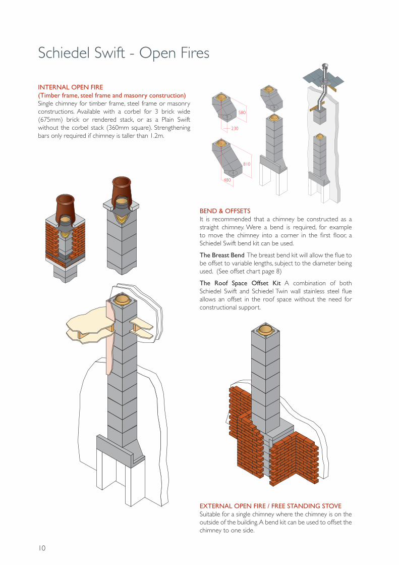
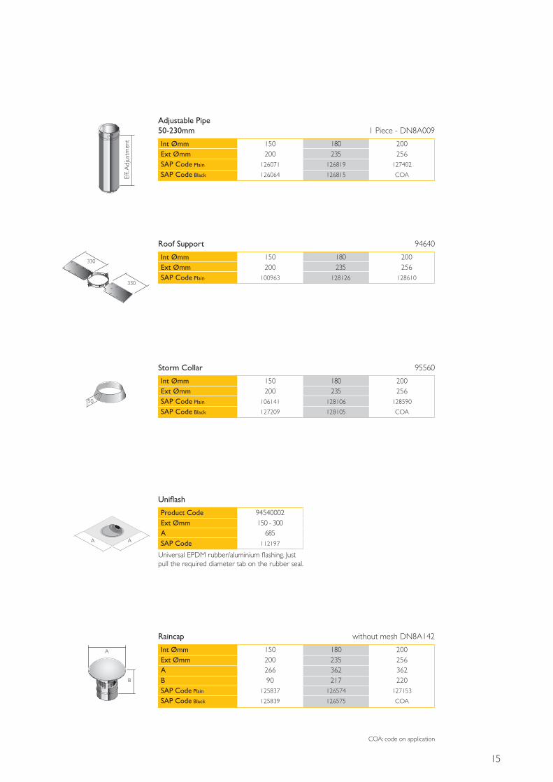
Adjustable Pipe 50-230mm 1 Piece - DN8A009
Int ØmmExt ØmmSAP Code Plain
SAP Code Black
150200
126071
126064
180235
126819
126815
200256
127402
COA
330
330
Roof Support 94640
Int ØmmExt ØmmSAP Code Plain
150200
100963
180235
128126
200256
128610
A
B
Raincap without mesh DN8A142
Int ØmmExt ØmmABSAP Code Plain
SAP Code Black
15020026690
125837
125839
180235362217
126574
126575
200256362220
127153
COA
Storm Collar 95560
Int ØmmExt ØmmSAP Code Plain
SAP Code Black
150200
106141
127209
180235
128106
128105
200256
128590
COA
50
Uniflash
Product CodeExt ØmmASAP Code
94540002150 - 300
685112197
Universal EPDM rubber/aluminium flashing. Just pull the required diameter tab on the rubber seal.
A A
COA: code on application

16
CHIMNEY CONSTRUCTION1. The first chimney block is set on a bed of mortar on top of the prefabricated gather or support block, depending on your appliance. Schiedel Rapid HT Cement is applied to the recess into which the liner will locate.
2. Bend and place the insulation into the chimney block. Care should be taken to ensure the slots in the mineral wool are compressed inwards. It is important the insulation is fitted as below to ensure consistent insulation around the flue pipe.
3. Place the flue liner into the chimney block. with the female rebate facing upwards. Arrows on each flue liner indicate the directional flow of flue gases. Continue to apply high temperature cement to each flue liner, cleaning any access material from the joints.
Schiedel Swift - Installation Guidelines
BUILDING REGULATIONSThe construction and application of chimneys and flues is covered by Building Regulations in conjunction with the relevant European Standards. Whilst these differ in emphasis, they all mandate the safe application of the chimney no matter where and how used. These Regulations and Standards dictate the minimum criteria which it is necessary to apply if the chimney or flue is to function safely and correctly.
Building control approval is necessary for building new chimneys and in some cases for relining old chimneys particularly if some alteration or change of the heating appliance occurs. The appropriate Regulations and Standards are listed below.
England & Wales: Building Regulations Approved Document J
Scotland: Building Regulations Technical Standards
Northern Ireland: Building Regulations Technical Booklet L
Republic of Ireland:Building Regulations Technical Guidance Document J
FLUE SIZINGIt is important to match the internal diameter of the flue with the outlet on the appliance. It should never be less than the outlet diameter of the appliance. The appliance manufacturer’s chimney sizing recommendations should always be followed.
For open fires with a standard fire opening up to 500mm wide by 550mm high the minimum required flue diameter is 200mm round. For larger open fires, such as inglenooks, dog grate installations or special appliances and stoves designed to operate with a fire opening greater than 500mm x 550mm, the flue size should be at least 15% of the free unobstructed area of the fire opening (including sides if open). Many Decorative Fuel Effect gas fires (DFE’s) that imitate a coal or log burning open fire require the same chimney arrangement as for solid fuel open fires and must be installed in accordance with respective local building regulations.
FOUNDATIONSConstruction begins by providing a suitable foundation and constructional hearth in accordance with Building Regulations and site requirements.
Rapid
Rapid
Rapid
Rapid

17
Schiedel Swift - Installation Guidelines
BEND KIT1. Build the chimney to the point where the bend is required. The steel locking band should be placed around the liner in the chimney block before the bend.
2. Place the first chimney bend block on top of the standard chimney block. Insert the first insulated flue bend.
3. Add the second chimney bend block with the angled edge face down. Make sure the block is properly supported.
5. Position the final bend block angle edge down to return the kit to the horizontal. The steel locking band should be placed around the liner in the chimney block before continuing to add more blocks.
4. Place the straight edge of the third chimney bend block on top. Insert the insulated ceramic return bend into the bend block
4. The chimney blocks should be tied every metre to a structural wall with the supplied masonry/steel frame ties.Standard timber frame ties (not included) should be used in timber frame construction.
1000mm
5. Where the chimney passes through floor or ceiling joists, these need to be trimmed out leaving a gap of 40mm for timber and 30mm for concrete. This gap is then filled with non-combustible material.
1000mm

18
Schiedel Swift - Installation Guidelines
4. Finally apply an exterior waterproof render.
2. Continue to build the chimney block on the corbel. Keep the cavity between the block and outer skin clear of mortar. A chimney tray is recommended for brick clad stacks. Fit the chimney tray over the chimney block and let it rest on the bricks as shown with the apron on the slope side. Wall weeps should be put into the brick joints to ventilate and remove any trapped moisture.
Chimney Trays are an additional option and can be produced to specific requirements.
Mortar
2. Place the coping on a bed of mortar on top of the DPC coping tray.
3. Place the chimney pot on the coping ensuring the space between the pot and coping is sealed with mortar or other non-porous material
RENDERED STACK1. Continue to build the chimney as a single block to the stack. Special plastic connectors are inserted in all 4 corners of the chimney block to provide stability against wind loading. These should be used from a point 1 metre below the last point of lateral support.
Reinforcement bars should be used instead of the plastic connectors for chimney stacks over 1.2m high. (see p. 17)
BRICK STACK1. A corbel is required for brick or block cladding. This give a stack of 675mm x 675mm or 3 bricks by 3 bricks.
Mortar
Mortar
Mortar
1000mm1000
Fold over lead tocover top edge of liner
Coping Tray
Insulation
Liner
Block
approx. 5mm

19
Schiedel Swift - Installation Guidelines
AFTER COMPLETIONAfter installation is complete tests and checks should be carried out in accordance with document J of the Building Regulations. A chimney notice plate must be completed and permanently fixed in the dwelling, ideally near the electrical consumer unit. The checklist and notice plate are available from Schiedel.
USE AND MAINTENANCEThe chimney should be left for at least 72 hours before use, then start only with small fires for the first week and gently increase thereafter.
The chimney should be swept at least twice a year, once before the heating season and once after the heating season. You may need to sweep during the heating season depending upon use. The brush should be a medium density polypropylene bristle type and should be the same diameter as the flue. Steel brushes must not be used to sweep the flues.
Always follow the appliance manufacturer’s operating instructions. Always burn approved fuels or dry seasoned wood. Avoid burning unseasoned wood and slow burning of solid fuels as this can produce excessive soot and condensation which in turn cause soot fires and damage. If correctly installed, operated and maintained these systems should last the life of the dwelling.
REINFORCING BARSReinforcement bars should be used instead of the plastic connectors for chimney stacks over 1.2m high. The bars must start 1m below the last point of lateral support.
1. Start by inserting the plastic stoppers into the holes on the block before the first one with bars.
3. Before placing the coping tray into position, ensure the chimney block and the outer skin are at the same level at the top of the stack. Place the coping tray into position on a bed of mortar and ensure the gap between chimney block and outer skin is sealed properly.
4. Place the coping on a bed of mortar on top of the DPC coping tray.
5. Place the chimney pot on the coping ensuring the space between the pot and coping is sealed with mortar or other non-porous material. Also inside the chimney pot seal the space between the pot and expansion plate with mortar or other non-porous material.
2. Screw the bars together and inset equal lengths into the 4 holes. The liquid grouting mortar should be poured into the reinforcing channels. Keep the reinforcing bars centred.
Mortar
Fold over lead tocover top edge of liner
Coping Tray
Insulation
Liner
Block
approx. 5mm

20
Schiedel Swift Air Chimney System ConceptManufactured to EN13063-1: 2003-8
The alternative to Schiedel Swift Air is low level or under floor ducting ideally with air supplies from opposite sides of the house.
The Schiedel Swift Air solution avoids this by ducting the air through an external air shaft in the chimney.
Available in 150mm, 180mm and 200mm internal flue diameters. The size of the chimney block is the same for each flue diameter - 500mm x 360mm x 330mm high.
In an A rated house the combustion air required for wood burning appliance like a stove burning logs or wood pellets must be supplied directly to the stove from outside the house.These appliances are called room sealed as they are manufactured not to take air from the room.The Schiedel Swift Air provides all the benefits of the Schiedel Swift and in addition neatly and simply delivers the external air to the stove.
TWO OPTIONS ARE AVAILABLE - Recess Stove- Free Standing Stove or Boiler

21
Schiedel Swift Air in an Energy Efficient House
Combustion air is supplied
directly to the stove from
outside the house.
Combustion air is supplied
directly to the boiler from
outside the house.
COLD
WARM
COLD
WARM
COLD
WARM
COLD
WARM
COLD
WARM
COLD
WARM
The heated air circulates within the house. The stove and the boiler do not take air from inside the house so no warm air is lost through the chimneys.- Schiedel, enabling energy efficiency.
22
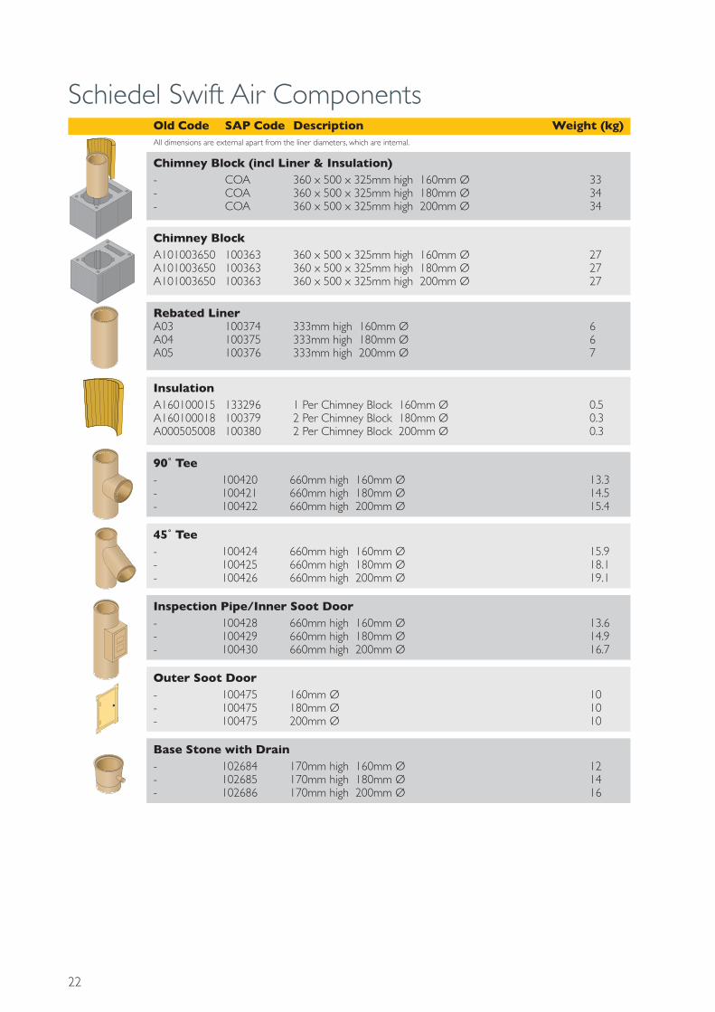
Schiedel Swift Air Components
Chimney Block (incl Liner & Insulation) - COA 360 x 500 x 325mm high 160mm Ø 33- COA 360 x 500 x 325mm high 180mm Ø 34- COA 360 x 500 x 325mm high 200mm Ø 34
Chimney Block A101003650 100363 360 x 500 x 325mm high 160mm Ø 27A101003650 100363 360 x 500 x 325mm high 180mm Ø 27A101003650 100363 360 x 500 x 325mm high 200mm Ø 27
InsulationA160100015 133296 1 Per Chimney Block 160mm Ø 0.5A160100018 100379 2 Per Chimney Block 180mm Ø 0.3A000505008 100380 2 Per Chimney Block 200mm Ø 0.3
Rebated LinerA03 100374 333mm high 160mm Ø 6A04 100375 333mm high 180mm Ø 6A05 100376 333mm high 200mm Ø 7
90˚ Tee- 100420 660mm high 160mm Ø 13.3- 100421 660mm high 180mm Ø 14.5- 100422 660mm high 200mm Ø 15.4
Inspection Pipe/Inner Soot Door- 100428 660mm high 160mm Ø 13.6- 100429 660mm high 180mm Ø 14.9- 100430 660mm high 200mm Ø 16.7
45˚ Tee- 100424 660mm high 160mm Ø 15.9- 100425 660mm high 180mm Ø 18.1- 100426 660mm high 200mm Ø 19.1
Outer Soot Door- 100475 160mm Ø 10- 100475 180mm Ø 10- 100475 200mm Ø 10
Base Stone with Drain- 102684 170mm high 160mm Ø 12- 102685 170mm high 180mm Ø 14- 102686 170mm high 200mm Ø 16
Old Code SAP Code Description Weight (kg)All dimensions are external apart from the liner diameters, which are internal.

23
Schiedel Swift Air Components
Starter Block - RecessA1800035 131182 500 x 360 x 100mm high 160mm Ø 20A1800036 130823 500 x 360 x 100mm high 180mm Ø 20- COA 500 x 360 x 100mm high 200mm Ø 20
Coping Tray - SmallA00061 130705 555 x 445mm 160mm Ø 15A00051 130671 556 x 445mm 180mm Ø 15A00062 130704 557 x 445mm 200mm Ø 15
Coping Tray - LargeA00053 130670 790 x 685mm 160mm Ø 18A00050 130672 791 x 685mm 180mm Ø 18- COA 792 x 685mm 200mm Ø 18
Universal Starter BlockA1800035 131181 500 x 360 x 100mm high 20
Lintel Stove HeadA1700003 130770 1500 x 150 x 75mm high 36
CorbelA25000206 131193 790 x 680 x 100mm high 88
Corbel - CutA25000208 131195 640 x 680 x 100mm high 88
HP3 Block- 137946 355 x 222 x 140mm -
HP5 Block- COA 400 x 222 x 140mm -
CopingA26000209 130701 900 x 790 x 70mm high Large 96A26000206 130702 650 x 500 x 70mm high Small 28
PF CopingA26000203 131197 900 x 770 x 70mm high Large 101A26000204 130700 630 x 530 x 70mm high Small 34
Wall TiesA1069001 130775 2 Per Metre -
Plastic ConnectorsA1069000 130800 4 Per Block -
Universal Adaptor- 108972 Universal Adaptor -
Schiedel RapidA17500100 100020 Rapid HT Cement (310ml) -
Air Pot- 130745 Air Pot -
Rapid
Old Code SAP Code Description Weight (kg)All dimensions are external apart from the liner diameters, which are internal.
Roll Top Pots1 129041 300mm high Buff 101 129042 300mm high Terracotta 101 129040 300mm high Black 10
Refer to pages 28 - 29 for full range of pots and terminals

24
Schiedel Swift Air - Installation Guidelines
BUILDING REGULATIONSThe construction and application of chimneys and flues is covered by Building Regulations in conjunction with the relevant European Standards. Whilst these differ in emphasis, they all mandate the safe application of the chimney no matter where and how used. These Regulations and Standards dictate the minimum criteria which it is necessary to apply if the chimney or flue is to function safely and correctly.
Building control approval is necessary for building new chimneys and in some cases for relining old chimneys particularly if some alteration or change of the heating appliance occurs. The appropriate Regulations and Standards are listed below.
England & Wales: Building Regulations Approved Document J
Scotland: Building Regulations Technical Standards
Northern Ireland: Building Regulations Technical Booklet L
Republic of Ireland:Building Regulations Technical Guidance Document J
FLUE SIZINGIt is important to match the internal diameter of the flue with the outlet on the appliance. It should never be less than the outlet diameter of the appliance. The appliance manufacturer’s chimney sizing recommendations should always be followed.
For open fires with a standard fire opening up to 500mm wide by 550mm high the minimum required flue diameter is 200mm round or 175mm square. For larger open fires, such as inglenooks, dog grate installations or special appliances and stoves designed to operate with a fire opening greater than 500mm x 550mm, the flue size should be at least 15% of the free unobstructed area of the fire opening (including sides if open). Many Decorative Fuel Effect gas fires (DFE’s) that imitate a coal or log burning open fire require the same chimney arrangement as for solid fuel open fires and must be installed in accordance with respective local building regulations
RECESSED STOVE OPTIONThe Schiedel Air System is a specially designed balanced flue that connects a Room Sealed Appliance to fresh air and enables combustion gases to escape safely. Therefore, in the majority of installations there is no need for air vents to be provided for the appliance.
1. The recess height and width are open to personal choice depending on the size of the heating appliance. The components provided allows for an opening of H1200mm x W900mm. If a wider opening is required you will need to source a longer lintel which must be certified to span the width of the recess and support 2,100kg. An additional lintel may be added to make the recess deeper as required.
2. Lay a damp proof course. Place the air block on a mortar bed and start to build the recess. The air block is 140mm deep, either use a block this deep or build a standard block flush with the front of the air block and leave a gap to the rear.
Mark the centre of air cavity on the front of the air block and place in centre of recess. The air block can be built tight against the wall. If timber frame construction, attach the plasterboard before constructing the recess and the chimney.
FOUNDATIONSConstruction begins by providing a suitable foundation and constructional hearth in accordance with Building Regulations and site requirements.
Not supplied
Equal
Equal
Centre ofair cavity

25
Schiedel Swift Air - Installation Guidelines
3. Build up the Air Block, (HP3), in line with standard block, alternating on each row to ensure the block will ‘tie in’ and form a staggered joint. Ensure the joints are completely sealed and the air cavity is kept clear of access mortar.
Once the desired height is reached add the lintel to the front of the recess. If necessary cut the top air block to sit level with top of the lintel. Complete the top course to the same height.
OFFSETSThere is no bend kit available for the Schiedel Air System however, an offset can be obtained by using the HP5 block within the stove recess. Each HP5 block has an offset of 120mm.
4. Lay a bed of mortar on lintel and air block. Place starter block on top of lintel and back wall, align the rectangular hole to the back so it matches with hole in the air block. Ensure that the joint between the air block and the support block is sealed with mortar. Run a bead of high temperature cement around the flue aperture on the support block.
Place the first chimney block on the support block. Wipe away any excess and mortar, particularly in the air chamber as you do not want to restrict the flow of air.
Apply Schiedel Rapid HT Cement to top nib
300
480
900
TYPICAL OFFSET USING HP5 BLOCKS
FREE STANDING STOVE OPTIONWith a Free Standing stove, the chimney will not be positioned above the appliance. It is then necessary to provide a cleaning access and debris removal area. If it is a condensing appliance, a base stone can be used to collect the condensate. Provision should be made for the proper disposal of condensate.

26
Schiedel Swift Air - Installation Guidelines
1. Core drill a suitable diameter hole in accordance with the appliance manufacturer’s instructions.
2. Cut out a section of wall between the air gap and the flue section in the first block no smaller than the cross-sectional area of the air channel. This allows the air intake to be placed at front or side of the block.
3. Ensure the exhaust outlet of the appliance is aligned with the junction pipe of the chimney.
4. Lay a damp proof course. Lay a bed of mortar and place the chimney block with the removed section into desired position. Add the required number of additional chimney blocks (refer to table on page 25) depending on how high the connecting tee needs to be to suit your appliance.
Place the universal starter block on a bed of mortar on top of this chimney block. Line up the air gap in the block with the air gap in the support block.
5. Apply a bed of mortar to the top of the universal starter block and place another chimney block.
6. Fill in the bottom half of the chimney shaft with mortarso as to allow for the inspection pipe to sit into. This will mean only having to cut one chimney block to accomodate the inspection pipe.
For condensing appliances you will need to use a base stone in place of the mortar to allow for the condensate to be drained off and disposed of.
7. Place the next cut chimney block on a bed of mortar. (A cardboard cutting template is supplied on the front of the inspection door)
It is essential that a mortar bed is laid between the air gap and flue aperture. bend the insulation around the inside of the chimney block. Once fitted, cut the insulation along the ventilation channel.
8. Put a bead of high temperature cement around the bottom rebate of the inspection pipe, place it in the chimney block (socket uppermost).
For timberframe applicationsthe system must be 40mmfrom the combustible material
Cut out wall section here
Hole for connecting appliance air intake
Alternative positon connecting for appliance air intake
Base Stone option for condensing applications
It is essential that a mortar bed is laid between the air gap and flue aperture
27
Schiedel Swift Air - Installation Guidelines
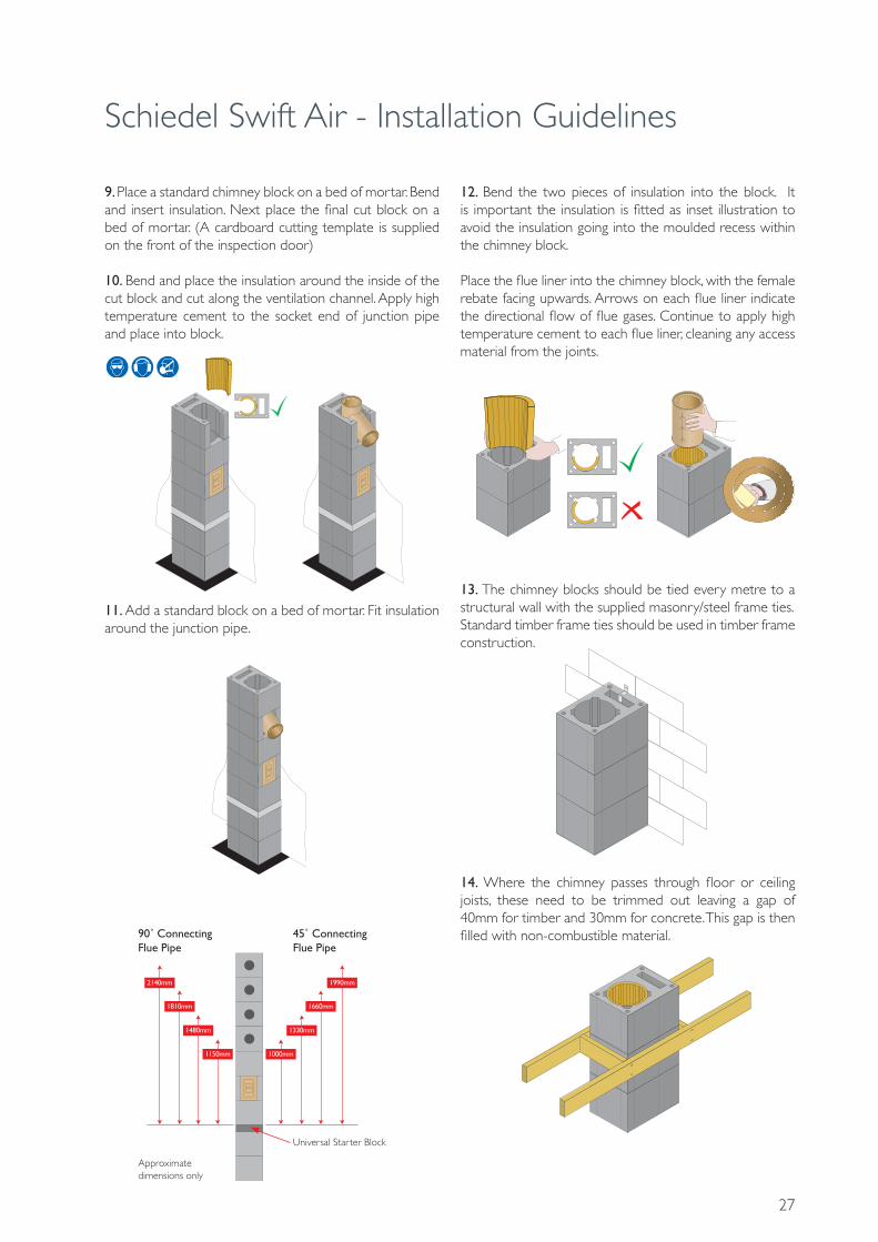
12. Bend the two pieces of insulation into the block. It is important the insulation is fitted as inset illustration to avoid the insulation going into the moulded recess within the chimney block.
Place the flue liner into the chimney block, with the female rebate facing upwards. Arrows on each flue liner indicate the directional flow of flue gases. Continue to apply high temperature cement to each flue liner, cleaning any access material from the joints.
13. The chimney blocks should be tied every metre to a structural wall with the supplied masonry/steel frame ties.Standard timber frame ties should be used in timber frame construction.
14. Where the chimney passes through floor or ceiling joists, these need to be trimmed out leaving a gap of 40mm for timber and 30mm for concrete. This gap is then filled with non-combustible material.
9. Place a standard chimney block on a bed of mortar. Bend and insert insulation. Next place the final cut block on a bed of mortar. (A cardboard cutting template is supplied on the front of the inspection door)
10. Bend and place the insulation around the inside of the cut block and cut along the ventilation channel. Apply high temperature cement to the socket end of junction pipe and place into block.
11. Add a standard block on a bed of mortar. Fit insulation around the junction pipe.
2140mm 1990mm
1810mm 1660mm
1480mm 1330mm
1150mm 1000mm
90˚ ConnectingFlue Pipe
Approximate dimensions only
45˚ ConnectingFlue Pipe
Universal Starter Block

Schiedel Swift Air - Installation Guidelines
28
4. Finally apply an exterior waterproof render.
2. Continue to build the chimney block on the corbel. Keep the cavity between the block and outer skin clear of mortar. A chimney tray is recommended for brick clad stacks. Fit the chimney tray over the chimney block and let it rest on the bricks as shown with the apron on the slope side. Wall weeps should be put into the brick joints to ventilate and remove any trapped moisture.
Chimney Trays are an additional option and can be produced to specific requirements.
2. Place the coping on a bed of mortar on top of the DPC coping tray.
3. Place the chimney pot on the coping ensuring the space between the pot and coping is sealed with mortar or other non-porous material
RENDERED STACK1. Continue to build the chimney as a single block to the stack. Special plastic connectors are inserted in all 4 corners of the chimney block to provide stability against wind loading. These should be used from a point 1 metre below the last point of lateral support.
Reinforcement bars should be used instead of the plastic connectors for chimney stacks over 1.2m high. (see p. 27)
BRICK STACK1. A corbel is required for brick or block cladding. This give a stack of 790mm x 680mm (3 bricks by 3.5 bricks).
Mortar
1000mm1000
Fold over lead tocover top edge of liner
Coping Tray
Insulation
Liner
Block
approx. 5mm

Schiedel Swift Air - Installation Guidelines
29
AFTER COMPLETIONAfter installation is complete tests and checks should be carried out in accordance with document J of the Building Regulations. A chimney notice plate must be completed and permanently fixed in the dwelling, ideally near the electrical consumer unit. The checklist and notice plate are available from Schiedel.
USE AND MAINTENANCEThe chimney should be left for at least 72 hours before use, then start only with small fires for the first week and gently increase thereafter.
The chimney should be swept at least twice a year, once before the heating season and once after the heating season. You may need to sweep during the heating season depending upon use. The brush should be a medium density polypropylene bristle type and should be the same diameter as the flue. Steel brushes must not be used to sweep the flues.
Always follow the appliance manufacturer’s operating instructions. Always burn approved fuels or dry seasoned wood. Avoid burning unseasoned wood and slow burning of solid fuels as this can produce excessive soot and condensation which in turn cause soot fires and damage. If correctly installed, operated and maintained these systems should last the life of the dwelling.
3. Before placing the coping tray into position, ensure the chimney block and the outer skin are at the same level at the top of the stack. Place the coping tray into position on a bed of mortar and ensure the gap between chimney block and outer skin is sealed properly.
4. Place the coping on a bed of mortar on top of the DPC coping tray.
5. Place the chimney pot on the coping ensuring the space between the pot and coping is sealed with mortar or other non-porous material. Also inside the chimney pot seal the space between the pot and expansion plate with mortar or other non-porous material.
2. Screw the bars together and inset equal lengths into the 4 holes. The liquid grouting mortar should be poured into the reinforcing channels. Keep the reinforcing bars centred.
Mortar
Fold over lead tocover top edge of liner
Coping Tray
Insulation
Liner
Block
approx. 5mm
REINFORCING BARSReinforcement bars should be used instead of the plastic connectors for chimney stacks over 1.2m high. The bars must start 1m below the last point of lateral support.
1. Start by inserting the plastic stoppers into the holes on the block before the first one with bars.

30
Chimney Pots & AccessoriesOld Code SAP Code Description Weight (kg)All dimensions are external unless otherwise stated
Roll Top Pots1 129041 300mm high Buff 101 129373 375mm high Buff 12.71 129753 450mm high Buff 15.41 130155 600mm high Buff 20.41 COA 750mm high Buff 25.41 COA 900mm high Buff 30.31 129042 300mm high Terracotta 101 129374 375mm high Terracotta 12.71 129754 450mm high Terracotta 15.41 130156 600mm high Terracotta 20.41 130447 750mm high Terracotta 25.41 130658 900mm high Terracotta 30.31 129040 300mm high Black 101 129372 375mm high Black 12.71 129752 450mm high Black 15.41 130154 600mm high Black 20.41 130446 750mm high Black 25.41 130657 900mm high Black 30.3
Rook43 129929 500mm high Buff 16.843 129930 500mm high Terracotta 16.843 129928 500mm high Black 16.8
Octagon Pot 340mm Base80 130149 600mm high Buff 29.680 130150 600mm high Terracotta 29.680 130148 600mm high Black 29.680 130441 750mm high Buff 33.580 130442 750mm high Terracotta 33.580 130440 750mm high Black 33.5
Octagon Pot 300mm Base81 130152 600mm high Buff 26.781 130153 600mm high Terracotta 26.781 130151 600mm high Black 26.781 130444 750mm high Buff 31.381 130445 750mm high Terracotta 31.381 130443 750mm high Black 31.3
Dublin Can52 130138 600mm high Buff 25.452 130139 600mm high Terracotta 25.452 130137 500mm high Black 25.4
Cannon Head Pots4 COA 300mm high Buff 10.64 129729 450mm high Buff 12.74 130135 600mm high Buff 50.44 COA 300mm high Terracotta 10.64 129728 450mm high Terracotta 12.74 130136 600mm high Terracotta 50.44 COA 300mm high Black 10.64 129727 450mm high Black 12.74 130134 600mm high Black 50.4

31
Chimney Pots & AccessoriesOld Code SAP Code Description Weight (kg)All dimensions are external unless otherwise stated
Hood Top30 127067 190mm high Buff 1230 127073 190mm high Terracotta 1230 127072 190mm high Black 12
Flue Ventilator120 127078 190mm high Buff 10120 127079 190mm high Terracotta 10120 127077 190mm high Black 10
Plain Ridge264 COA 450mm Buff 8264 COA 450mm Terracotta 8264 COA 450mm Black 8
Capped Angle Ridge285 COA 450mm Buff 10285 COA 450mm Terracotta 10285 COA 450mm Black 10
Roll Top Ridge284 COA 450mm Buff 11284 COA 450mm Terracotta 11284 COA 450mm Black 11
Club Crested Ridge288 COA 300mm Buff 7288 COA 300mm Terracotta 7288 COA 300mm Black 7
Mushroom Top118 127075 190mm high Buff 10118 127076 190mm high Terracotta 10118 127074 190mm high Black 10
GC2 Insert612 COA 190mm high Buff 14612 127066 190mm high Terracotta 14612 127065 190mm high Black 14
Chimney Holder- 100514 -
Reinforcing Bars16447401 130801 1 metre each -
Firebrick- 112562 230 x114 x 25mm 1.4- 115281 230 x114 x 50mm 2.8- 130769 230 x114 x 76mm 4.2

Schiedel Chimney SystemsWashingbay RoadCoalislandCo. TyroneBT71 4NDTel. +44 (0)28 8774 0436Fax. +44 (0)28 8774 [email protected]
Complementary products and servicesfrom Schiedel Chimney Systems
ICSTwin Wall Insulated System Chimney for gas,oil and multi-fuel applications.
• Simple push-fit jointing system• High efficiency Superwool insulation blanket• Capillary break prevents moisture being drawn through the joint• 80-300mm Diameter range
TECNOFLEX PLUSFor relining existing chimneys to take gas, oil,wood, multi-fuel appliances and open fires.
• Twin skin TecnoFlex Plus available in 316L or 904L options for oil, wood, multi-fuel & open fires
• 80-300mm Diameter range
ECO ICIDThe NEW highly Insulated Twin Wall SystemChimney for stoves.
• Easy twist lock connection• Effective insulation• 125-200mm Internal diameter range
PRIMA SMOOTHSingle Wall Stainless Steel Connecting Flue Pipe for use on wood and multi-fuel applications.
• 316L Grade stainless steel• Available in matt black or steel finish• Excellent aesthetics• Lightweight• 125-200mm internal diameters
full details at www.schiedel.co.uk
HETAS TRAININGCourses H001-H006 available. See website for course prospectus and application form downloads or scan the QR code a direct link.
ABSOLUT XPERTAbsolut XPert is part of the new innovative ceramic range of System Chimneys for Energy Efficient and Passivhaus construction.
PRIMA PLUSSingle Wall Stainless Steel Flue System.
• Prima Plus available 0.6mm for domestic multi-fuel stoves• Prima Plus for large residential & commercial condensing gas & oil appliances & chimney relining• 80-300mm Diameter range
Follow SchiedelUK on: