
The Guide to Being a Logisim User - faculty.kfupm.edu.sa Guide to... · • Logisim libraries are...
123
The Guide to Being a Logisim User Logisim is an educational tool for designing and simulating digital logic circuits. With its simple toolbar interface and simulation of circuits as they are built, it is simple enough to facilitate learning the most basic concepts related to logic circuits. With the capacity to build larger circuits from smaller subcircuits, and to draw bundles of wires with a single mouse drag, Logisim can be used (and is used) to design and simulate entire CPUs for educational purposes. Students at colleges and universities around the world use Logisim for a variety of purposes, including: • A module in general-education computer science surveys • A unit in sophomore-level computer organization courses • Over a full semester in upper-division computer architecture courses The Guide to Being a Logisim User, which you are reading now, is the official reference for Logisim's features. Its first part is a sequence of sections introducing the major parts of Logisim. These sections are written so that they can be read ``cover to cover'' to learn about all of the most important features of Logisim. Beginner's tutorial Libraries and attributes Subcircuits Wire bundles Combinational analysis
Transcript of The Guide to Being a Logisim User - faculty.kfupm.edu.sa Guide to... · • Logisim libraries are...

The Guide to Being a Logisim User
Logisim is an educational tool for designing and simulating digital logic circuits. With its simple toolbar interface and simulation of circuits as they are built, it is simple enough to facilitate learning the most basic concepts related to logic circuits. With the capacity to build larger circuits from smaller subcircuits, and to draw bundles of wires with a single mouse drag, Logisim can be used (and is used) to design and simulate entire CPUs for educational purposes.
Students at colleges and universities around the world use Logisim for a variety of purposes, including:
• A module in general-education computer science surveys • A unit in sophomore-level computer organization courses • Over a full semester in upper-division computer architecture courses
The Guide to Being a Logisim User, which you are reading now, is the official reference for Logisim's features. Its first part is a sequence of sections introducing the major parts of Logisim. These sections are written so that they can be read ``cover to cover'' to learn about all of the most important features of Logisim.
Beginner's tutorial Libraries and attributes Subcircuits Wire bundles Combinational analysis
The remaining sections are a motley bunch of reference materials and explanations of some of the lesser corners of Logisim.
Menu reference Memory components Logging Application preferences Project options Value propagation JAR libraries About the program
Beginner's tutorial Welcome to Logisim!
Logisim allows you to design and simulate digital circuits. It is intended as an educational tool, to help you learn how circuits work.
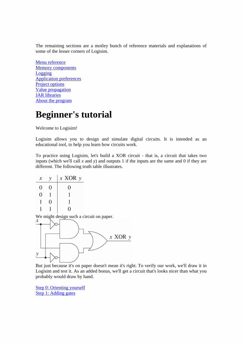
To practice using Logisim, let's build a XOR circuit - that is, a circuit that takes two inputs (which we'll call x and y) and outputs 1 if the inputs are the same and 0 if they are different. The following truth table illustrates.
We might design such a circuit on paper.
But just because it's on paper doesn't mean it's right. To verify our work, we'll draw it in Logisim and test it. As an added bonus, we'll get a circuit that's looks nicer than what you probably would draw by hand.
Step 0: Orienting yourself Step 1: Adding gates

Step 2: Adding wires Step 3: Adding text Step 4: Testing your circuit
Enjoy your circuit-building!
Next: Step 0: Orienting yourself
Step 0: Orienting yourself
When you start Logisim, you'll see a window similar to the following. Since you'll be using a different system, some of the details may be slightly different.
All Logisim is divided into three parts, called the explorer pane, the attribute table, and the canvas. Above these parts are the menu bar and the toolbar.

We can quickly dispose of the explorer pane and the attribute table: We won't be examining them in this tutorial, and you can just ignore them. Also, the menu bar is self-explanatory.
That leaves the toolbar and the canvas. The canvas is where you'll draw your circuit; and the toolbar contains the tools that you'll use to accomplish this.
Next: Step 1: Adding gates
Step 1: Adding gates
Recall that we're trying to build the following circuit in Logisim.
Building a circuit is easiest by inserting the gates first as a sort of skeleton for connecting wires into the circuit later. The first thing we're going to do is to add the two AND gates. Click on the AND tool in the toolbar ( , the next-to-last tool listed). Then click in the editing area where you want the AND gates to go. Be sure to leave plenty of room for stuff on the left.
Notice the five dots on the left side of the AND gate. These are spots where wires can be attached. It happens that we'll just use two of them for our XOR circuit; but for other circuits, you may find that having more than two wires going to an AND gate is useful.
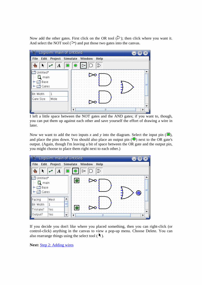
Now add the other gates. First click on the OR tool ( ); then click where you want it. And select the NOT tool ( ) and put those two gates into the canvas.
I left a little space between the NOT gates and the AND gates; if you want to, though, you can put them up against each other and save yourself the effort of drawing a wire in later.
Now we want to add the two inputs x and y into the diagram. Select the input pin ( ), and place the pins down. You should also place an output pin ( ) next to the OR gate's output. (Again, though I'm leaving a bit of space between the OR gate and the output pin, you might choose to place them right next to each other.)
If you decide you don't like where you placed something, then you can right-click (or control-click) anything in the canvas to view a pop-up menu. Choose Delete. You can also rearrange things using the select tool ( ).
Next: Step 2: Adding wires

Step 2: Adding wires
After you have all the components blocked out on the canvas, you're ready to start adding wires. Select the wiring tool ( ). Then start dragging from one position to another in the canvas area, and a wire will start to appear between the two points.
Wires in Logisim must be horizontal or vertical. To connect the upper input to the NOT gate and the AND gate, then, I added three different wires.
Logisim automatically connects wires to the gates and to each other. This includes automatically drawing the circle at a T intersection as above, indicating that the wires are connected.
As you draw wires, you may see some blue or gray wires. Blue in Logisim indicates that the value at that point is ``unknown'', and gray indicates that the wire is not connected to anything. This is not a big deal temporarily. But by the time you finish your circuit, none of your wires should be blue or gray. (The unconnected legs of the OR gate will still be blue: That's fine.)
If you do have a blue or a gray wire after you think everything ought to be connected, then something is going wrong. It's important that you connect wires to the right places. Logisim draws little dots on the components to indicate where wires ought to connect. As you proceed, you'll see the dots turn from blue to light or dark green.
Once you have all the wires connected, all of the wires you inserted will themselves be light or dark green.

Next: Step 3: Adding text
Step 3: Adding text
Adding text to the circuit isn't necessary to make it work; but if you want to show your circuit to somebody (like a teacher), then some labels help to to communicate the purpose of the different pieces of your circuit.
Select the text tool ( ). You can click on an input pin and start typing to give it a label. (It's better to click directly on the input pin than to click where you want the text to go, because then the label will move with the pin.) You can do the same for the output pin. Or you could just click any old place and start typing to put a label anywhere else.
Next: Step 4: Testing your circuit

Step 4: Testing your circuit
Our final step is to test our circuit to ensure that it really does what we intended. Logisim is already simulating the circuit. Let's look again at where we were.
Note that the input pins both contain 0s; and so does the output pin. This already tells us that the circuit already computes a 0 when both inputs are 0.
Now to try another combination of inputs. Select the poke tool ( ) and start poking the inputs by clicking on them. Each time you poke an input, its value will toggle. For example, we might first poke the bottom input.
When you change the input value, Logisim will show you what values travel down the wires by drawing them light green to indicate a 1 value or dark green (almost black) to indicate a 0 value. You can also see that the output value has changed to 1.
So far, we have tested the first two rows of our truth table, and the outputs (0 and 1) match the desired outputs.

By poking the switches through different combinations, we can verify the other two rows. If they all match, then we're done: The circuit works!
To archive your completed work, you might want to save or print your circuit. The File menu allows this, and of course it also allows you to exit Logisim. But why quit now?
Now that you are finished with tutorial, you can experiment with Logisim by building your own circuits. If you want to build circuits with more sophisticated features, then you should navigate through the rest of the help system to see what else you can do. Logisim is a powerful program, allowing you to build up and test huge circuits; this step-by-step process just scratches the surface.
Libraries and Attributes In this section, we'll examine how to use the other two major regions of the Logisim window, the explorer pane and the attribute table.
The explorer pane The attribute table Tool and component attributes
Next: The explorer pane.
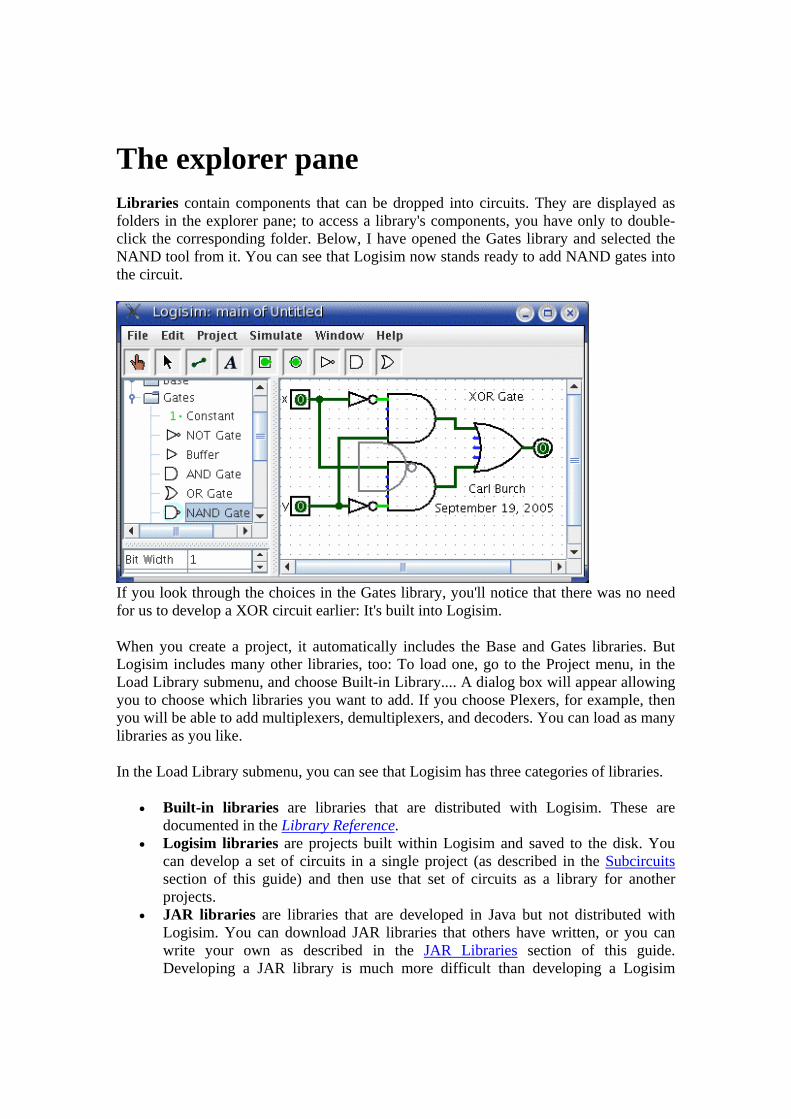
The explorer pane Libraries contain components that can be dropped into circuits. They are displayed as folders in the explorer pane; to access a library's components, you have only to double-click the corresponding folder. Below, I have opened the Gates library and selected the NAND tool from it. You can see that Logisim now stands ready to add NAND gates into the circuit.
If you look through the choices in the Gates library, you'll notice that there was no need for us to develop a XOR circuit earlier: It's built into Logisim.
When you create a project, it automatically includes the Base and Gates libraries. But Logisim includes many other libraries, too: To load one, go to the Project menu, in the Load Library submenu, and choose Built-in Library.... A dialog box will appear allowing you to choose which libraries you want to add. If you choose Plexers, for example, then you will be able to add multiplexers, demultiplexers, and decoders. You can load as many libraries as you like.
In the Load Library submenu, you can see that Logisim has three categories of libraries.
• Built-in libraries are libraries that are distributed with Logisim. These are documented in the Library Reference.
• Logisim libraries are projects built within Logisim and saved to the disk. You can develop a set of circuits in a single project (as described in the Subcircuits section of this guide) and then use that set of circuits as a library for another projects.
• JAR libraries are libraries that are developed in Java but not distributed with Logisim. You can download JAR libraries that others have written, or you can write your own as described in the JAR Libraries section of this guide. Developing a JAR library is much more difficult than developing a Logisim

library, but the components can be much fancier, including things like attributes and interaction with the user. The built-in libraries (other than Base) were written using the same API as JAR libraries can use, so they aptly demonstrate the range of functionality that the JAR libraries can support.
When loading a JAR library, Logisim will prompt you to select the JAR file, and then it will prompt you to type a class name. This class name should be provided by whoever distributed the JAR file to you.
To remove a library, choose Unload Library... from the Project menu. Logisim will prevent you from unloading libraries that contain components used in a circuit, that appear in the toolbar, or that are mapped to a mouse button.
Incidentally, a library technically contains tools, not components. Thus, in the Base library you'll find the Poke Tool ( ), the Select Tool ( ), and other tools that don't correspond directly to individual components. Most libraries, though, contain only tools for adding individual components; all built-in libraries other than the Base library are like this.
Next: The attribute table.
The attribute table Many components have attributes, which are properties for configuring how the component behaves or appears. The attribute table is for viewing and displaying a component's attribute values.
To select which component's attributes you wish to view, click the component using the Select tool ( ). (You can also right-click (or control-click) the component and choose Show Attributes from the popup menu. Also, manipulating a component via the Poke tool ( ) or the Text tool ( ) will display that component's attributes.)
The below screen shot demonstrates what things look like after selecting the upper input of our XOR circuit and scrolling down to view the Label Font attribute.
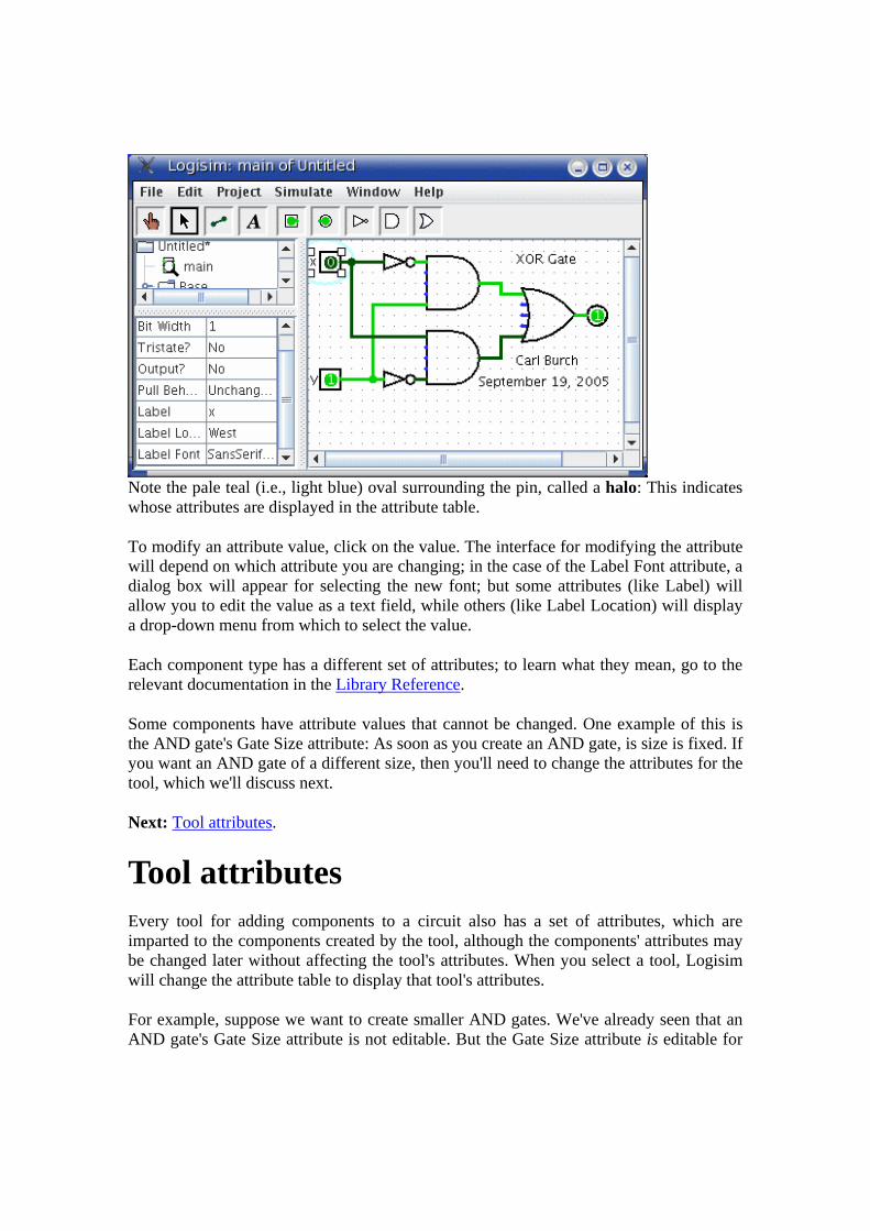
Note the pale teal (i.e., light blue) oval surrounding the pin, called a halo: This indicates whose attributes are displayed in the attribute table.
To modify an attribute value, click on the value. The interface for modifying the attribute will depend on which attribute you are changing; in the case of the Label Font attribute, a dialog box will appear for selecting the new font; but some attributes (like Label) will allow you to edit the value as a text field, while others (like Label Location) will display a drop-down menu from which to select the value.
Each component type has a different set of attributes; to learn what they mean, go to the relevant documentation in the Library Reference.
Some components have attribute values that cannot be changed. One example of this is the AND gate's Gate Size attribute: As soon as you create an AND gate, is size is fixed. If you want an AND gate of a different size, then you'll need to change the attributes for the tool, which we'll discuss next.
Next: Tool attributes.
Tool attributes Every tool for adding components to a circuit also has a set of attributes, which are imparted to the components created by the tool, although the components' attributes may be changed later without affecting the tool's attributes. When you select a tool, Logisim will change the attribute table to display that tool's attributes.
For example, suppose we want to create smaller AND gates. We've already seen that an AND gate's Gate Size attribute is not editable. But the Gate Size attribute is editable for

the AND gate tool: To view and edit this attribute, click the tool's icon in the toolbar (or the explorer pane), and change its Gate Size attribute.
Now, we can delete the two existing AND gates and add two new AND gates in their place. This time, they will be narrow. (If you chose to reduce the number of inputs to 3, the AND gate would not have vertical extension on the left side. But you'd also have to rewire the circuit so that the wires hit the AND gate's left side.)
With some tools, the icon reflects some of the attributes' values. One example of this is with the Pin tool, whose icon faces the same way as its Facing attribute says.
The tools in the toolbar each have a separate attribute set from the corresponding tools in the explorer pane. Thus, even though we changed the toolbar's AND tool to create narrow AND gates, the AND tool in the Gates library will still create wide AND gates unless you change its attributes too.
In fact, the input pin and output pin tools in the default toolbar are both instances of the Base library's Pin tool, but the three attribute sets are different. The icon for the Pin tool is drawn as a circle or a square depending on the value of its ``Output?'' attribute.

Logisim provides a handy shortcut for changing the Facing attribute that controls the direction in which many components face: Typing an arrow key while that tool is selected automatically changes the direction of the component.
Subcircuits As you build circuits that are more and more sophisticated, you will want to build smaller circuits that you can use multiple times in larger circuits. In Logisim, such a smaller circuit that is used in a larger circuit is called a subcircuit.
If you're familiar with computer programming, you're familiar with the subprogram concept (called subroutines, functions, or methods in different languages). The subcircuit concept is analogous to the concept in computer programming, and it is used for the same purposes: To break a large job into bite-sized pieces, to save the effort of defining the same concept multiple times, and to facilitate debugging.
Creating circuits Using subcircuits Debugging subcircuits Logisim libraries
Next: Creating circuits.
Creating circuits Every Logisim project is actually a library of circuits. In its simplest form, each project has only one circuit (called "main" by default), but it is easy to add more: Select Add Circuit... from the Project menu, and type any name you like for the new circuit you want to create.
Suppose we want to build a 1x2 multiplexer named "1x2 MUX." After adding the circuit, Logisim will look like this.

In the explorer pane, you can now see that the project now contains two circuits, "main", and "1x2 MUX." Logisim draws a magnifying glass over the icon of the circuit currently being viewed; the current circuit name also appears in the window's title bar.
After editing the circuit to appear like a 1x2 multiplexer, we might end up with the following circuit.
Next: Using subcircuits.
Using subcircuits Now suppose we want to build a 2x4 multiplexer using instances of our 1x2 multiplexer. Of course, we would first create a new circuit, which we'll call "2x4 MUX." To add 1x2 multiplexers into our circuit, we click the 1x2 MUX circuit once in the explorer pane to select it as a tool, and then we can add copies of it, represented as boxes, by clicking within the canvas.

If you click the 1x2 MUX circuit twice in the explorer pane, then the window would switch to editing the 1x2 MUX circuit instead.
After building up the circuit, we end up with the following.
Our circuit for a 2x4 multiplexer uses three copies of the 1x2 multiplexer, each drawn as a box with pins along the side. The pins on this box correspond to the input and output pins in the 1x2 MUX circuit. The two pins on the west side of the box correspond to the two pins that face east in the 1x2 MUX circuit; the pin on the box's east side corresponds to the 1x2 MUX's west-facing pin (which happens to be an output pin); and the pin on the box's south side corresponds to the 1x2 MUX's north-facing pin. The order of the two pins on the box's west side correspond to the same top-down ordering that apears in the subcircuit. (If there were several pins on the box's north or south side, they would correspond to the same left-right order in the subcircuit.)
If the pins in the subcircuit's layout have labels associated with them, then Logisim will display that label in a tip (that is, a temporary text box) when the user hovers the mouse over the corresponding location of the subcircuit component. (If you find these tips irritating, you can disable them via the Project Options window's Canvas tab.)

Several other components will display these tips, too: For some of the pins of a built-in flip-flop, for example, hovering over it explains what that pin does.
Incidentally, every pin to a circuit must be either an input or an output. Many manufactured chips have pins that behave as an input in some situations and as an output in others; you cannot construct such chips within Logisim.
Logisim will maintain different state information for all subcircuits appearing in a circuit. For example, if a circuit contains a flip-flop, and that circuit is used as a subcircuit several times, then each subcircuit's flip-flop will have its own value when simulating the larger circuit.
Now that we have the 2x4 multiplexer defined, we can now use it in other circuits. Logisim has no limits on how deeply circuits can be nested - though it will object to nesting circuits within themselves!
Note: There's nothing wrong with editing a circuit that is being used as a subcircuit; in fact, this is quite common. Be aware, though, that any changes to a circuit's pins (adding, deleting, or moving them) will rearrange them also in the containing circuit. Thus, if you change any pins in a circuit, you will also need to edit any circuits using it as a subcircuit.
Next: Debugging subcircuits.
Debugging subcircuits As you test larger circuits, you will likely find bugs. To nail down what's going wrong, exploring what's going on in the subcircuits while running the overall circuit can help. From viewing the overall circuit, you can do this by bringing up the subcircuit's popup menu (right-click or control-click its box). Then choose the View option.

After choosing this, the view will switch to the subcircuit.
Notice that the pins' values in the subcircuit match the values being sent to them in its containing circuit.
While in the subcircuit, you can change it however you want; any changes to pins' values will be propagated within the containing circuit. (If you attempt to toggle a pin using the Poke Tool, Logisim will pop up a dialog box asking whether you want to create a new state; responding Yes will divorce the state viewed with the subcircuit from the outer circuit's state, while responding No will cancel the toggle request.)
Once you have completed viewing and/or editing the parent circuit either by double-clicking it in the explorer pane, or via the Go Out To State submenu of the Simulate menu.
Next: Logisim libraries.

Logisim libraries Every Logisim project is automatically a library that can be loaded into other Logisim projects: Just save it into a file and then load the library within another project. All of the circuits defined in the first project will then be available as subcircuits for the second. This feature allows you to reuse common components across projects and to share favorite components with your friends (or students).
Each project has a designated "main circuit," which can be changed to refer to the current circuit via the Set As Main Circuit option in the Project menu. The only significance of this is that the main circuit is the one that is displayed when you first open the project. The default name of the circuit in a newly created file ("main") has no significance at all, and you can feel free to delete or rename that circuit.
With a loaded Logisim library, you are allowed to view circuits and manipulate their states, but Logisim will prevent you from altering them.
If you want to alter a circuit in a loaded Logisim library, then you need to open it separately within Logisim. As soon as you save it, the other project should automatically load the modified version immediately; but if it does not, you can right-click the library folder in the explorer pane and select Reload Library.
Wire bundles In simple Logisim circuits, most wires carry only one bit; but Logisim also allows you to create wires that bundle together multiple bits. The number of bits traveling along a wire is that wire's bit width.
Creating bundles Splitters Wire colors
Next: Creating bundles.
Creating bundles Every input and output on every component in the circuit has a bit width associated with it. Many of Logisim's built-in components include attributes allowing you to customize the bit widths of their inputs and outputs.
The below screen shot illustrates a simple circuit for finding the bitwise AND of two three-bit inputs; each pin has its Bit Width attribute customized for dealing with three-bit data, as with the pictured AND gate attributes.

Notice that the input and output pins are drawn with three bits, and the output is the bitwise AND of the inputs.
For components, all inputs and outputs must have their bit widths defined. In contrast, a wire's bit width is undefined: Instead, the wire's width adapts to the components to which it is attached. If a wire connects two components demanding different bit widths, Logisim will complain of ``Incompatible widths'' and indicate the offending locations in orange. In the below, the output pin's Bit Width attribute has been changed to 1, and so Logisim complains that the wire cannot connect a three-bit value to a one-bit value.
Wires that connect incompatible locations (drawn in orange) do not carry values.
For single-bit wires, you can see at a glance what value it is carrying because Logisim colors the wire light or dark green depending the value. It does not display values for multi-bit wires: They are simply black. You can, though, probe a wire by clicking it using the poke tool ( ).

This probing feature is helpful for debugging circuits using wire bundles.
Next: Splitters.
Splitters When you work with multi-bit values, you will often want to route different bits in different directions. The Base library's splitter tool ( allows you to accomplish this.
For example, suppose we want to build a circuit taking an eight-bit input and outputting the AND of its two nibbles (the upper four bits and the lower four bits). We will have an eight-bit value coming from the input pin, and we want to split that into two four-bit values. In the below circuit, we have used a splitter to accomplish this.
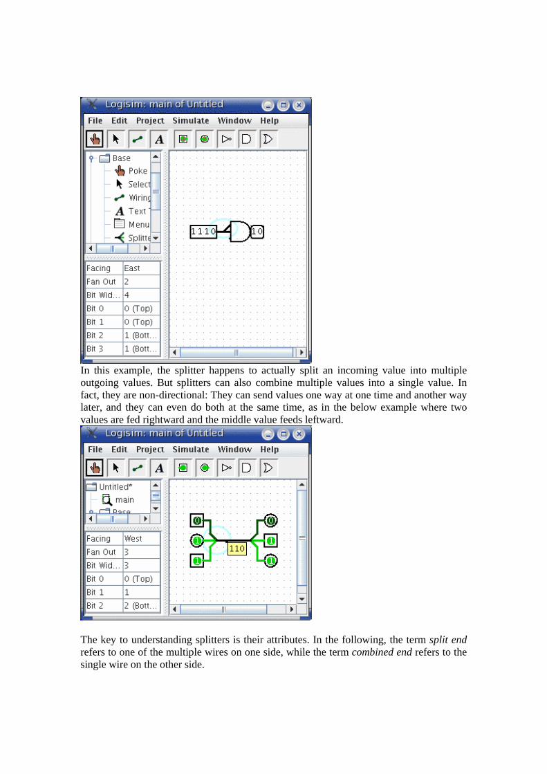
In this example, the splitter happens to actually split an incoming value into multiple outgoing values. But splitters can also combine multiple values into a single value. In fact, they are non-directional: They can send values one way at one time and another way later, and they can even do both at the same time, as in the below example where two values are fed rightward and the middle value feeds leftward.
The key to understanding splitters is their attributes. In the following, the term split end refers to one of the multiple wires on one side, while the term combined end refers to the single wire on the other side.
• The Facing attribute tells where the split ends should be relative to the combined end. This cannot be changed once a splitter is dropped into the circuit.
• The Fan Out attribute specifies how many split ends there are. This also cannot be changed once a splitter is dropped into the circuit.
• The Bit Width attribute specifies the bit width of the combined end. • The Bit x attribute says which split end corresponds to bit x of the combined end.
If multiple bits correspond to the same split end, then their relative ordering will be the same as in the combined end. Logisim splitters cannot have a bit from the combined end correspond to multiple split ends.
Note that any change to the Fan Out or Bit Width attributes will reset all Bit x attributes so that they will distribute the bits of the combined value as evenly as possible among the split ends.
Next: Wire colors.
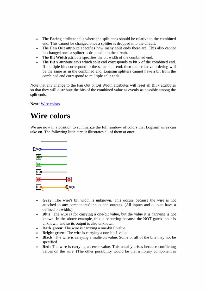
Wire colors We are now in a position to summarize the full rainbow of colors that Logisim wires can take on. The following little circuit illustrates all of them at once.
• Gray: The wire's bit width is unknown. This occurs because the wire is not attached to any components' inputs and outputs. (All inputs and outputs have a defined bit width.)
• Blue: The wire is for carrying a one-bit value, but the value it is carrying is not known. In the above example, this is occurring because the NOT gate's input is unknown, and so its output is also unknown.
• Dark green: The wire is carrying a one-bit 0 value. • Bright green: The wire is carrying a one-bit 1 value. • Black: The wire is carrying a multi-bit value. Some or all of the bits may not be
specified. • Red: The wire is carrying an error value. This usually arises because conflicting
values on the wire. (The other possibility would be that a library component is

programmed to emit an error value for another reason; in the built-in libraries, though, error values arise only from propagating other error values.) In the above example, we have one input pin placing a 0 on the wire and another placing a 1 on the wire, causing a conflict. Multi-bit wires will turn red when any of the bits carried are error values.
• Orange: The components attached to the wire do not agree in bit width. An orange wire is effectively "broken": It does not carry values between components.
Next: User's Guide.
Combinational analysis
All circuits fall into one of two well-known categories: In a combinational circuit, all circuit outputs are a strict combination of the current circuit inputs, whereas in a sequential circuit, some outputs may depend on past inputs (the sequence of inputs over time).
The category of combinational circuits is the simpler of the two. Practitioners use three major techniques for summarizing the behavior of such circuits.
• logic circuits • Boolean expressions, which allow an algebraic representation of how the circuit
works

• truth tables, which list all possible input combinations and the corresponding outputs
The Combinational Analysis module of Logisim allows you to convert between these three representations in all directions. It is a particularly handy way of creating and understanding circuits with a handful of one-bit inputs and outputs. Opening Combinational Analysis Editing the truth table Creating expressions Generating a circuit
Next: Opening Combinational Analysis.
Opening Combinational Analysis The bulk of the Combinational Analysis module is accessed through a single window of that name allowing you to view truth tables and Boolean expressions. This window can be opened in two ways.
Via the Window menu
Select Combinational Analysis, and the current Combinational Analysis window will appear. If you haven't viewed the window before, the opened window will represent no circuit at all.
Only one Combinational Analysis window exists within Logisim, no matter how many projects are open. There is no way to have two different analysis windows open at once.
Via the Project menu
From a window for editing circuits, you can also request that Logisim analyze the current circuit by selecting the Analyze Circuit option from the Project menu. Before Logisim opens the window, it will compute Boolean expressions and a truth table corresponding to the circuit and place them there for you to view.
For the analysis to be successful, each input must be attached to an input pin, and each output must be attached to an output pin. Logisim will only analyze circuits with at most eight of each type, and all should be single-bit pins. Otherwise, you will see an error message and the window will not open.
In constructing Boolean expressions corresponding to a circuit, Logisim will first attempt to construct a Boolean expressions corresponding exactly to the gates in the circuit. But if the circuit uses some non-gate components (such as a multiplexer), or if the circuit is more than 100 levels deep (unlikely), then it will pop up a dialog box telling you that deriving Boolean expressions was impossible, and Logisim will instead derive the

expressions based on the truth table, which will be derived by quietly trying each combination of inputs and reading the resulting outputs.
After analyzing a circuit, there is no continuing relationship between the circuit and the Combinational Analysis window. That is, changes to the circuit will not be reflected in the window, nor will changes to the Boolean expressions and/or truth table in the window be reflected in the circuit. Of course, you are always free to analyze a circuit again; and, as we will see later, you can replace the circuit with a circuit corresponding to what appears in the Combinational Analysis window.
Limitations
Logisim will not attempt to detect sequential circuits: If you tell it to analyze a sequential circuit, it will still create a truth table and corresponding Boolean expressions, although these will not accurately summarize the circuit behavior. (In fact, detecting sequential circuits is provably impossible, as it would amount to solving the Halting Problem. Of course, you might hope that Logisim would make at least some attempt - perhaps look for flip-flops or cycles in the wires - but it does not.) As a result, the Combinational Analysis system should not be used indiscriminately: Only use it when you are indeed sure that the circuit you are analyzing is indeed combinational!
Logisim will make a change to the original circuit that is perhaps unexpected: The Combinational Analysis system requires that each input and output have a unique name that conforming to the rules for Java identifiers. (Roughly, each character must either a letter or a digit, and the first character must be a letter. No spaces allowed!) It attempts to use the pins' existing labels, and to use a list of defaults if no label exists. If an existing label doesn't follow the Java-identifier rule, then Logisim will attempt to extract a valid name from the label if at all possible.
Incidentally, the ordering of the inputs in the truth table will match their top-down ordering in the original circuit, with ties being broken in left-right order. (The same applies to the ordering of outputs.)
Next: Editing the truth table.

Editing the truth table On opening the Combinational Analysis window, you will see that it consists of five tabs.
This page describes the first three tabs, Inputs, Outputs, and Table. The next page of the guide describes the last two tabs, Expression and Minimized.
The Inputs and Outputs tabs
The Inputs tab allows you to view and edit the list of inputs. To add new inputs, type it in the field at the pane's bottom, and click Add. If you want to rename an existing input, select it in the list in the pane's upper left region; then type the name and click Rename.
To remove an input, select it from the list and click Remove. You can also reorder the inputs (which affects the order of columns in the truth table and in the generated circuit) using the Move Up or Move Down buttons on an input.
All actions affect the truth table immediately.
The Outputs tab works in exactly the same way as the Inputs tab, except of course it works with the list of outputs instead.
The Table tab
The only item under the Table tab is the current truth table, diagrammed in the conventional order, with inputs constituting the columns on the left and outputs constituting the columns on the right.
You can edit the current values appearing in the output columns by clicking on the value of interest. The values will cycle through 0, 1, and x (representing a "don't care"). As we'll see on the next page, any don't-care values allow the computation of minimized expressions some flexibility.
You can also navigate and edit the truth table using the keyboard. And you can copy and paste values using the clipboard. The clipboard can be transferred to any application supporting tab-delimited text (such as a spreadsheet).
If the truth table is based on an existing circuit, you may see some pink squares in the output columns with "!!" in them. These correspond to errors that occurred while calculating the value for that row - either the circuit seemed to be oscillating, or the output value was an error value (which would be pictured as a red wire in the Logisim circuit). Hovering your mouse over the entry should bring up a tool tip describing which type of error it was. Once you click on the error entry, you will be in the 0-1-x cycle; there is no way to go back.
Next: Creating expressions.
Creating expressions For each output variable, the Combinational Analysis window maintains two structures - the relevant column of the truth table, and a Boolean expression - specifying how each output relates to its input. You can edit either the truth table or the expression; the other will automatically change as necessary to keep them consistent.
As we will see on the next page, the Boolean expressions are particularly useful because the Combinational Analysis window will use these when told to build a circuit corresponding to the current state.
You can view and edit the expressions using the window's last two tabs, the Expression tab and the Minimized tab.
The Expression tab
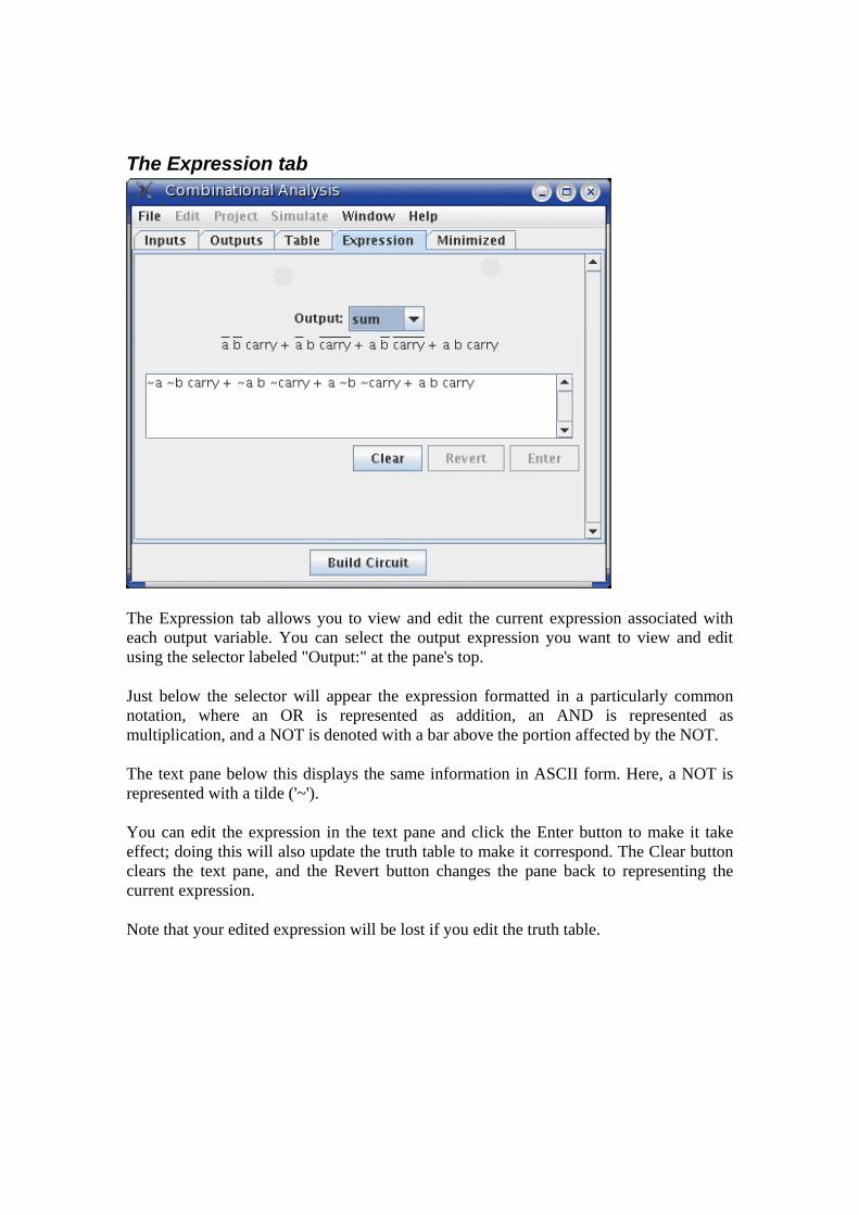
The Expression tab allows you to view and edit the current expression associated with each output variable. You can select the output expression you want to view and edit using the selector labeled "Output:" at the pane's top.
Just below the selector will appear the expression formatted in a particularly common notation, where an OR is represented as addition, an AND is represented as multiplication, and a NOT is denoted with a bar above the portion affected by the NOT.
The text pane below this displays the same information in ASCII form. Here, a NOT is represented with a tilde ('~').
You can edit the expression in the text pane and click the Enter button to make it take effect; doing this will also update the truth table to make it correspond. The Clear button clears the text pane, and the Revert button changes the pane back to representing the current expression.
Note that your edited expression will be lost if you edit the truth table.

In addition to multiplication and addition standing for AND and OR, an expression you type may contain any of C/Java logical operators, as well as simply the words themselves.
highest precedence ~ ! NOT (none) & && AND ^ XORlowest precedence + | || OR
The following examples are all valid representations of the same expression. You could also mix the operators. ~a (b + c) !a && (b || c) NOT a AND (b OR c) In general, parentheses within a sequence of ANDs (or ORs or XORs) do not matter. (In particular, when Logisim creates a corresponding circuit, it will ignore such parentheses.)
The Minimized tab
The final tab displays a minimized sum-of-products expression corresponding to a column of the truth table. You can select which output's minimized expression you want to view using the selector at top.
If there are four or fewer inputs, a Karnaugh map corresponding to the variable will appear below the selector. You can click the Karnaugh map to change the corresponding

truth table values. The Karnaugh map will also display the currently selected terms for the minimized expression as solid semitransparent rounded rectangles.
Below this is the minimized expression itself, formatted as in the Expression tab's display. If there are more than four inputs, the Karnaugh map will not appear; but the minimized expression will still be computed. (Logisim uses the Quine-McCluskey algorithm to compute the minimized expression. This is equivalent to a Karnaugh map, but it applies to any number of input variables.)
The Set As Expression button allows you to select the minimized expression as the expression corresponding to the variable. This will generally not be necessary, as edits to the truth table result in using the minimized expression for the changed column; but if you enter an expression through the Expression tab, this can be a convenient way to switch to the corresponding minimized expression.
Next: Generating a circuit.
Generating a circuit The Build Circuit button will construct a circuit whose gates correspond to the currently chosen expressions for each output. The circuit's inputs and outputs will be displayed in top-down order corresponding to how they appear under the Inputs and Outputs tabs. Generally speaking, the constructed circuit will be attractive; and, indeed, one application of Logisim's Combinational Analysis module is to beautify poorly drawn circuits. Still, as with any automatic formatting, it will not express the structural details that a human-drawn circuit would.
When you click the Build Circuit button, a dialog box will appear prompting you to choose which project where you want the circuit and the name you wish to give it. If you type the name of an existing circuit, then that circuit will be replaced (after Logisim prompts you to confirm that you really want to do this).
The Build Circuit dialog includes two options. The Use Two-Input Gates Only option specifies that you want all gates constructed to have two inputs. (NOT gates, of course, constitute an exception to this rule.) The Use NAND Gates Only option specifies that you would like it to translate the circuit into one using only NAND gates. You can select both options if you want to use only two-input NAND gates.
Logisim cannot construct a NAND-only circuit for an expression containing any XOR operators. This option will therefore be disabled if any outputs' expressions contain XORs.

Menu Reference This section explains the six menus that accompany every major Logisim window.
The File menu The Edit menu The Project menu The Simulate menu The Window and Help menus Many menu items relate specifically to a currently opened project. But some Logisim windows (particularly the Combinational Analysis window and the Application Preferences window) are not associated with projects. For these windows, the project-specific menu items will be disabled.
Next: The File menu.
The File menu New
Opens a new project in a new window. The project will initially be a copy of the currently selected template.
Open... Opens an existing file as a project in a new window.
You can open files saved in Version 1.0X of Logisim, but there may be some slight conversion problems for complex circuits. Most notably, Logisim 1.0X computes subcircuit locations in a very different way, and you will need manually to go through all circuits and move the subcircuits to their correct locations.
Close Closes all windows associated with the currently viewed project.
Save Saves the currently viewed project, overwriting what was previously in the file.
Save As... Saves the currently viewed project, prompting the user to save into a different file than before.
Export As GIF... Creates GIF image(s) corresponding to circuits. The configuration dialog box is described below.
Print... Sends circuit(s) to a printer. The configuration dialog box is described below.
Preferences... Displays the application preferences window. (On Mac OS systems, this will appear in the Logisim menu.)

Exit Closes all currently open projects and terminates Logisim. (On Mac OS systems, this will appear as Quit in the Logisim menu.)
Configuring Export
When you select Export As GIF..., Logisim displays a dialog box with three options.
• Circuits: A list where you can select one or more circuits that should be exported into GIF files. (Empty circuits are not displayed as options.)
• Scale Factor: You can scale the images as they are dumped into GIF files using this slider.
• Printer View: Whether to use ``printer view'' in exporting the circuits.
After clicking OK, Logisim will display a file selection dialog box. If you have selected one circuit, select the file into which the GIF should be placed. If you have selected multiple circuits, select a directory where the files should be placed; Logisim will name the images based on the circuits' names (main.gif, for example).
Configuring Print
When you choose Print..., Logisim displays a dialog box for configuring what is printed.
• Circuits: A list where you can select one or more circuits to be printed. (Empty circuits are not displayed as options.) Logisim will print one circuit per page. If the circuit is too large for the page, the image will be scaled down to fit.
• Header: Text that should appear centered at the top of each page. The following substitutions will be made into the text.
%n Name of circuit on page %p Page number %P Total page count %% A single percent sign ('%')
• Rotate To Fit: If checked, then Logisim will rotate each circuit by 90 degrees when the circuit is too large to fit onto the page and it does not need to be scaled as small when rotated 90 degrees.
• Printer View: Whether to use ``printer view'' in printing the circuits.
After clicking OK, Logisim will display the standard page setup dialog box before printing the circuits.
Next: The Edit menu.

The Edit menu Undo XX
Undoes the most recently completed action affecting how the circuit would be saved in a file. Note that this does not include changes to the circuit state (as with manipulations performed by the Poke Tool).
Cut Removes the currently selected components from the circuit onto Logisim's clipboard.
Note: Logisim's clipboard is maintained separately from the clipboard for the overall system; as a result, cut/copy/paste will not work across different applications, even including other running copies of Logisim. If, however, you have multiple projects open under the same Logisim process, then you should be able to cut/copy/paste between them.
Copy Copies the currently selected components in the circuit onto Logisim's clipboard. (See the note under the Cut menu item.)
Paste Pastes the components on Logisim's clipboard into the current selection. (See the note under the Cut menu item.)
When you paste components, they will not immediately be dropped; instead, they will be drawn in light gray. They will not actually be ``dropped'' into the circuit until you either move the selection or change the selection so that the components are no longer in it.
The reason for this odd behavior is this: To be consistent with its other behavior, Logisim must immediately merge any wires as soon as they are dropped into a circuit; this merging process changes existing wires in the circuit. When you paste wires from the clipboard, however, you may to place them in a different location, and the changing inherent in the merging process would be against your wishes.
Delete Removes all components in the current selection from the circuit.
Select All Selects all components in the current circuit.
Next: The Project menu.

The Project menu Add Circuit...
Adds a new circuit into the current project. Logisim will insist that you name the new circuit. The name must not match any existing circuits in the project.
Load Library Loads a library into the project. You can load three types of libraries, as explained elsewhere in the User's Guide.
Unload Libraries... Unloads current libraries from the circuit. Logisim will not permit you to unload any libraries currently being used, including libraries containing components appearing in any project circuits, as well as those with tools that appear in the toolbar or that are mapped to the mouse.
Analyze Circuit Computes a truth table and Boolean expressions corresponding to the current circuit, displaying them in the Combinational Analysis window. The analysis process will only be valid for combinational circuits. A full description of the analysis process is described in the Combinational Analysis section.
Rename Circuit... Renames the currently displayed circuit.
Set As Main Circuit Sets the currently displayed circuit to be the project's ``main circuit.'' (This menu item will be grayed out if the current circuit is already the project's main circuit.) The only significance of the main circuit is that it is the circuit that first appears when a project file is opened.
Remove Circuit... Removes the currently displayed circuit from the project. Logisim will prevent you from removing circuits that are used as subcircuits, and it will prevent you from removing the final circuit in a project.
Options... Opens the Project Options window.
Next: The Simulate menu.
The Simulate menu Simulate Enabled
If checked, circuits viewed will be ``live:'' That is, the values propagating through the circuit will be updated with each poke or change to the circuit.
The menu option will be automatically unchecked if circuit oscillation is detected.

Reset Simulation Clears everything about the current circuit's state, so that it is as if you have just opened the file again. If you are viewing a subcircuit's state, the entire hierarchy is cleared.
Go Out To State When you delve into a subcircuit's state via its pop-up menu, this menu lists the circuits above the currently viewed circuit's state. Selecting one displays the corresponding circuit.
Go In To State If you have delved into a subcircuit's state and then moved back out, this menu lists the subcircuits below the current circuit. Selecting one of the circuits displays the corresponding circuit.
Tick Once Steps one tick forward into the simulation. This can be useful when you want to step the clocks manually, particularly when the clock is not in the same circuit that you are currently viewing.
Ticks Enabled Starts automatically ticking the clock. This will have an effect only if the circuit contains any clock devices (in the Base library). The option is disabled by default.
Tick Frequency Allows you to select how often ticks occur. For example, 8 Hz means that ticks will occur eight times a second. A tick is the base unit of measurement for the speed of clocks.
Note that the clock cycle speed will be slower than the tick speed: The fastest possible clock will have a one-tick up cycle and a one-tick down cycle; such a clock would have up/down cycle rate of 4 Hz if the ticks occur at 8 Hz.
Logging... Enters the logging module, which facilitates automatically noting and saving values in a circuit as a simulation progresses.
Next: The Window and Help menus.
The Window menu Minimize
Minimizes (iconifies) the current window. Zoom
Resizes the current window to its preferred size. Combinational Analysis
Shows the current Combinational Analysis window, without changing any of its contents.
individual window titles Brings the respective window to the front.
The Help menu Tutorial
Opens the on-line help system to the `Beginner's Tutorial' section of the Guide to Being a Logisim User.
User's Guide Opens the on-line help system to the Guide to Being a Logisim User.
Library Reference Opens the on-line help system to the Library Reference.
About... Displays a window containing the version number, mixed among the splash screen graphics. (On Mac OS, this menu item is under the Logisim menu.)
Library Reference A Logisim library holds a set of tools that allow you to interact with a circuit via clicking and dragging the mouse in the canvas area. Most often, a tool is intended for adding components of a particular type into a circuit; but some of the most important tools, such as the Poke Tool and the Select Tool, allow you to interact with components in other ways.
All of the tools included in Logisim's built-in libraries are documented in this reference material.
Base library Poke Tool Select Tool Wiring Tool Text Tool Menu Tool Splitter Pin Probe Clock Label
Gates library
Constant NOT Gate
Buffer

AND/OR/NAND/NOR Gate
XOR/XNOR/Odd Parity/Even Parity Gate
Controlled Buffer/Inverter Memory library
D/T/J-K/S-R Flip-Flop Register RAM ROM
Plexers library
Multiplexer Demultiplexer Decoder Bit Selector
Arithmetic library
Adder Subtractor Multiplier Divider Negator Comparator
Legacy library
Logisim 1.0 D/J-K Flip-Flop Logisim 1.0 8-Bit Register

Base library The Base library includes general-purpose tools, as well as components whose behavior in a circuit is distinguished from other components (that is, they are treated unusually by Logisim's propation engine).
Poke Tool Select Tool Wiring Tool Text Tool Menu Tool Splitter Pin Probe Clock Label
Poke Tool Library: Base Introduced: 2.0 Beta 1
Behavior
The Poke Tool is for manipulating the current values associated with components. The precise behavior of the Poke Tool varies depending on which component is clicked; this behavior is documented in the `Poke Tool Behavior' section of each individual component. The following components all have support for the Poke Tool.
Base library Pin Clock
Memory library D/T/J-K/S-R Flip-Flop Register RAM
Legacy library Logisim 1.0 D/J-K Flip-FlopLogisim 1.0 8-Bit Register
Also, clicking a wire segment using the Poke tool displays the value currently carried by the wire, as described on the Wiring Tool's page.
Attributes
None. Clicking on a component supporting the Poke Tool, though, will display that component's attributes.
Select Tool Library: Base Introduced: 2.0 Beta 1
Behavior
Allows individual components to be placed into the current selection. There are a number of actions possible with this tool.
• Pressing the mouse button while it is within a currently selected component begins a drag moving all components of the selection.
Dragging a selection can lead to unexpected behavior from wires: If you drag a selection including some wires on top of some other wires, all wires are merged, and the merged wires are placed into the selection. As a result, if you drag the selection a second time, the wires previously at the location will not be left behind. This behavior is necessary to keep with the expected behavior of wires in Logisim. And it does not normally constitute a major problem: Logisim will draw the full selection in the midst of dropping, and you should not drop it until you are sure it is in the correct location.
• Otherwise, clicking the mouse within a component drops all components from the current selection and selects instead the component(s) containing the clicked location.
• Shift-clicking the mouse within a component toggles that component's presence within the selection. If multiple components include the same location, all components' presence will be toggled. None of this will happen, though, if shift-clicking is mapped to another tool instead (via the project options window's Mouse tab).
• Dragging the mouse starting at a location not contained within any components drops all components from the current selection and initiates a rectangular selection. All component(s) contained by the rectangle will be placed into the selection.
• Shift-dragging the mouse starting at a location not contained within any components initiates a rectangular selection. The presence in the selection of all component(s) contained by the rectangle will be toggled. This will not happen, though, if shift-clicking is mapped to another tool instead.

After selecting the desired items in the selection, you can of course cut/copy/paste/delete all the items via the Edit menu.
Logisim's behavior when pasting the clipboard into a circuit is somewhat peculiar: It will not immediately place the components into the circuit; instead, the selection will be a collection of "ghosts," which will be dropped into the circuit as soon as they are either dragged to another location or removed from the selection. (This peculiar behavior is necessary because pasting will otherwise merge the wires of the selection into the current circuit at once, and the wires there previously will be dragged with the pasted clipboard if the user wants to move the pasted components somewhere else.)
Attributes
None. Selecting a component, though, will display its attributes.
Wiring Tool Library: Base Introduced: 2.0 Beta 1
Behavior
The wiring tool is the tool for creating wire segments that carry values from one endpoint to another. The bit width of these values can be anything; exactly which bit width is automatically inferred from the components to which the wires are ultimately attached. If it is not attached to any components, the wire will be drawn gray to indicate that its bit width is unknown; if the components at the locations that the wire helps to connect disagree on the bit width, then the wire will be drawn orange to indicate the conflict, and the wire will in fact refuse to carry any values at all until the user resolves the conflict.
A single drag of the mouse can create multiple wire segments. The precise process is a little confusing in its description; but it works quite intuitively in practice: If you request a particular wire segment using the Wiring Tool, that segment will be split apart wherever it hits a pin for an existing component, or wherever it hits the endpoint of an existing wire segment. Also, if an endpoint of any of the new wire segments hit somewhere in the middle of an existing wire, then that wire will be split into multiple segments itself.
For some components that draw short stubs to which wires can connect (such as an OR gate or a controlled buffer), Logisim will silently correct attempts to create wires that slightly overshoot the stub's end.
You can also shorten an existing wire segment using the Wiring Tool, using a drag that starts or ends at a terminus of the segment, and that overlaps the existing segment.

All wires in Logisim are either horizontal or vertical.
Wires are also non-directional; that is, they carry values from either endpoint to the other. Indeed, a wire can carry values in both directions simultaneously; the center wire in the below example is doing this.
Attributes
The wiring tool does not itself have attributes, but the wires that it creates do.
Direction Indicates whether the wire is horizontal or vertical. The value of this attribute cannot be changed.
Length Indicates how many pixels long the wire is. The value of this attribute cannot be changed.
Poke Tool Behavior
When you click an existing wire segment using the Poke Tool, Logisim displays the current value traveling through that wire. This is illustrated in the above screen shot of a wire carrying values in both directions simultaneously. The behavior is particularly useful for multi-bit wires, whose black color provide no visual feedback about what value the wire is carrying.
Back to Library Reference

Text Tool Library: Base Introduced: 2.0 Beta 1
Behavior
The text tool allows you to create and edit labels associated with components. Which components support labels are indicated in the 'Text Tool Behavior' section of their documentation. As of the current release, three components in the built-in libraries support labels.
Base library Pin ClockLabel
Clicking on one of these components using the text tool indicates that you wish to edit the label associated with that component, even if you click the component nowhere near where the label will actually appear. Clicks at other locations indicate that you wish to create a new label component.
In the current version of Logisim, text editing features are still fairly primitive. Selections of a region of text within a label is impossible. There is no way to insert a line break into a label.
Attributes
The attributes for the tool are the same as for the label component. These attributes have no effect when editing the label on an existing component, but they are imparted to any labels created using the text tool.
Clicking on a component supporting the Text Tool will display that component's attributes.
Back to Library Reference
Menu Tool Library: Base Introduced: 2.0 Beta 1

Behavior
The menu tool permits the user to pull up a pop-up menu for components that already exist. By default, right-clicking or control-clicking a component will bring up this pop-up menu; however, the Mouse tab of the project options allows a user to configure the mouse buttons to work differently.
The pop-up menu for most components has two items.
• Delete: Removes the component from the circuit. • Show Attributes: Places the component's attributes into the window's attribute
table, so that the attribute values can be viewed and changed.
For some components, however, the menu has additional items. Subcircuits (that is, instances of using one circuit as a "black box" within another) are one example of this: In addition to the above two items, the pop-up menu includes another item.
• View XXX: Changes the circuit layout being viewed and edited to be the subcircuit's layout instead. The values seen in the layout will be part of the same hierarchy as those of the supercircuit. (See the `Debugging subcircuits' section of the User's Guide.)
Other components may extend the pop-up menu also. In the built-in libraries of the current version of Logisim, the only such component is RAM.
Attributes
None.
Back to Library Reference
Splitter Library: Base Introduced: 2.0 Beta 1 Appearance:
Behavior
The splitter is intended for corresponding subsets of bits to the bits within a multi-bit value. Despite its name, it can either split a multi-bit value into component parts, or it can combine component parts into a multi-bit value, or it can do both at once. A more complete description of splitters is found in the `Splitters' section of the User's Guide.

Logisim treats splitters specially when propagating values within a circuit: Whereas all other components have a computed delay for purposes of simulating their behavior, values propagate through splitters (as well as wires) instantaneously.
Note: The term splitter is a non-standard term, which is unique to Logisim as far as I know. I am unaware of any standard term for such a concept; the only term I have heard used is bus ripper, but this term is unnecessarily violent for my tastes.
Pins
To distinguish the several connecting points for a splitter, we refer to the single connecting point one side as its combined end, and we refer to the multiple connecting points on the other side as its split ends.
Combined end (input/output bit width matches Bit Width attribute) A value holding all of the bits traveling through the splitter.
Split ends (input/output, bit width computed based on Bit x attributes) The number of split ends is specified in the Fan Out attribute, and each split end has an index that is at least 0 and less than the Fan Out attribute. For each split end, all bits for which Bit x refers to its index travels through that split end; the order of these bits is the same as their order within the combined end.
Attributes Facing
The location of the split ends relative to the combined end. Fan Out
The number of split ends. Bit Width
The bit width of the combined end. Bit x
The index of the split end to which bit x of the combined end corresponds. The split ends are indexed starting from 0 at the top (for a splitter facing east or west) or from 0 at the left/west (for a splitter facing north or south). A bit can be specified to correspond to none of the split ends. There is no way for a bit to correspond to multiple split ends.
Poke Tool Behavior
None.
Text Tool Behavior
None.
Back to Library Reference
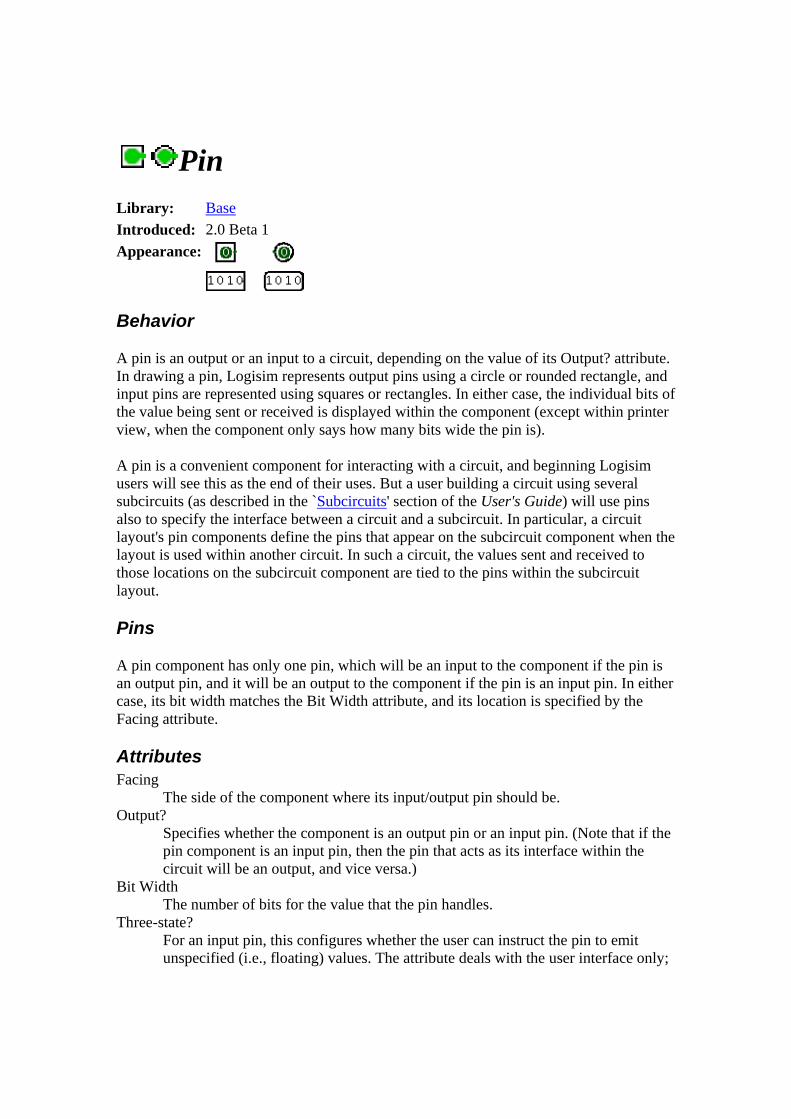
Pin Library: Base Introduced: 2.0 Beta 1 Appearance:
Behavior
A pin is an output or an input to a circuit, depending on the value of its Output? attribute. In drawing a pin, Logisim represents output pins using a circle or rounded rectangle, and input pins are represented using squares or rectangles. In either case, the individual bits of the value being sent or received is displayed within the component (except within printer view, when the component only says how many bits wide the pin is).
A pin is a convenient component for interacting with a circuit, and beginning Logisim users will see this as the end of their uses. But a user building a circuit using several subcircuits (as described in the `Subcircuits' section of the User's Guide) will use pins also to specify the interface between a circuit and a subcircuit. In particular, a circuit layout's pin components define the pins that appear on the subcircuit component when the layout is used within another circuit. In such a circuit, the values sent and received to those locations on the subcircuit component are tied to the pins within the subcircuit layout.
Pins
A pin component has only one pin, which will be an input to the component if the pin is an output pin, and it will be an output to the component if the pin is an input pin. In either case, its bit width matches the Bit Width attribute, and its location is specified by the Facing attribute.
Attributes Facing
The side of the component where its input/output pin should be. Output?
Specifies whether the component is an output pin or an input pin. (Note that if the pin component is an input pin, then the pin that acts as its interface within the circuit will be an output, and vice versa.)
Bit Width The number of bits for the value that the pin handles.
Three-state? For an input pin, this configures whether the user can instruct the pin to emit unspecified (i.e., floating) values. The attribute deals with the user interface only;

it does not have any effect on how the pin behaves when the circuit layout is used as a subcircuit. For an output pin, the attribute has no effect.
Pull Behavior For an input pin, the attribute specifies how floating values should be treated when received as an input, perhaps from a circuit using the layout as a subcircuit. With "unchanged," the floating values are sent into the layout as floating values; with "pull up," they are converted into 1 values before being sent into the circuit layout; and with "pull down," they are converted into 0 values before being sent into the circuit layout.
Label The text within the label associated with the component.
Label Location The location of the label relative to the component.
Label Font The font with which to render the label.
Poke Tool Behavior
Clicking an output pin has no effect, although the pin's attributes will be displayed.
Clicking an input pin will toggle the bit that is clicked. If it is a three-state pin, then the corresponding bit will rotate between the three states.
If, however, the user is viewing the state of a subcircuit as described in the `Debugging Subcircuits' of the User's Guide, then the pin's value is pinned to whatever value the subcircuit is receiving from the containing circuit. The user cannot change the value without breaking this link between the subcircuit's state and the containing circuit's state, and Logisim will prompt the user to verify that breaking this link is actually desired.
Text Tool Behavior
Allows the label associated with the component to be edited.
Back to Library Reference
Probe Library: Base Introduced: 2.0.3 Appearance:
Behavior
A probe is an element that simply display the value at a given point in a circuit. It does not itself interact with other components.
In most respects, the probe component duplicates the functionality found in a Pin component configured as an output pin. The only difference is that if the circuit is used as a subcircuit component, then an output pin will be a part of that interface, whereas a probe is not. Graphically, they are similar but have slightly different borders: A pin has a thick, black border, whereas a probe has a thin, gray border.
Pins
A probe component has only one pin, which will acts as an input to the probe. The width that this pin accepts is adaptive: The probe will adapt to inputs of any width.
Attributes Facing
The side of the component where its input pin should be. Label
The text within the label associated with the component. Label Location
The location of the label relative to the component. Label Font
The font with which to render the label.
Poke Tool Behavior
None.
Text Tool Behavior
Allows the label associated with the component to be edited.
Back to Library Reference

Clock Library: Base Introduced: 2.0 Beta 13 Appearance:
Behavior
The clock toggles its output value on a regular schedule as long as ticks are enabled via the Simulate menu. (Ticks are disabled by default.) A "tick" is Logisim's unit of time; the speed at which ticks occur can be selected from the Simulate menu's Tick Frequency submenu.
The clock's cycle can be configured using its High Duration and Low Duration attributes.
Note that Logisim's simulation of clocks is quite unrealistic: In real circuits, multiple clocks will drift from one another and will never move in lock step. But in Logisim, all clocks experience ticks at the same rate.
Pins
A clock has only one pin, an output with a bit width of 1, whose value will represent the current value of the clock. The location of this pin is specified in the Facing attribute. The clock's value will toggle on its schedule whenever ticks are enabled, and it will toggle whenever it is clicked using the Poke Tool.
Attributes Facing
The side of the component where its output pin should be. High Duration
The length of time within each cycle that the clock's output should be 1. Low Duration
The length of time within each cycle that the clock's output should be 0. Label
The text within the label associated with the clock component. Label Location
The location of the label relative to the component. Label Font
The font with which to render the label.
Poke Tool Behavior
Clicking a clock component will toggle its current output value immediately.

Text Tool Behavior
Allows the label associated with the component to be edited.
B Label Library: Base Introduced: 2.0 Beta 1 Appearance:
Behavior
This is a simple text label that can be placed anywhere in the circuit. It does not interact with values traveling through the circuit in any way, except inasmuch as it will be visible when the circuit is drawn.
In contrast to all other components in the current built-in libraries, label components can be placed anywhere on the canvas; they do not snap to the grid.
Pins
None.
Attributes Text
The text appearing in the label. This value can be edited in the attribute table or, using the text tool, on the canvas.
Font The font to use when drawing the label.
Horizontal Alignment The horizontal positioning technique for the text relative to the label's official location (where the mouse was clicked in creating the label). "Left" means that the text should be drawn so that its left edge is at the location; "right" means that the text should be drawn so that its right edge is at the location; and "center" means that the text should be drawn so that its center (horizontally) is at the location.
Vertical Alignment The vertical positioning technique for the text relative to the label's official location (where the mouse was clicked in creating the label). "Base" means that the baseline should intersect the location; "Top" means that the text's top should intersect the location; "Bottom" means that the text's bottom should intersect the location; and "Center" means that the text should be centered (vertically) at the location.

The text's top and bottom is computed based on the font's standard ascent and descent values; thus, even if the actual text contains no tall letters (such as b) or descending letters (such as g), it is assumed to contain such letters for the purposes of vertical positioning.
Poke Tool Behavior
None.
Text Tool Behavior
Allows the text appearing within the label to be edited.
Back to Library Reference
ack to Library Reference
Gates library The Gates library includes a variety of simple components, all of which have a single output whose value is dictated entirely by the current inputs.
Constant NOT Gate
Buffer AND/OR/NAND/NOR Gate
XOR/XNOR/Odd Parity/Even Parity Gate
Controlled Buffer/Inverter
Back to Library Reference

Constant Library: Gates Introduced: 2.0 Beta 1 Appearance:
Behavior
Emits the value specified in its Value attribute.
Pins
There is only one pin, an output whose bit width matches the Bit Width attribute. The location of this pin is specified in the Facing attribute. The component constantly outputs on this pin whatever value specified in the Value attribute.
Attributes Facing
The direction in which the pin is located relative to where the value is drawn. Bit Width
The bit width of the component's inputs and outputs. Value
The value, written in hexademical, that is emitted by the component. The number of bits used to specify the value cannot exceed the component's bit width.
Poke Tool Behavior
None.
Text Tool Behavior
None.
Back to Library Reference
NOT Gate Library: Base Introduced: 2.0 Beta 1 Appearance:

Behavior
The NOT Gate emits the complement of whatever input it receives. The truth table for a NOT gate is the following.
x out0 1 1 0
If the input is unspecified (i.e., floating), or if it is the error value, then the output will have the same value.
A multi-bit NOT gate will perform the above transformation bitwise on its input.
Pins West edge (input, bit width according to Bit Width attribute)
The component's input. East edge (output, bit width according to Bit Width attribute)
The output, whose value is the complement of the input value.
Attributes Facing
The direction of the component (its output relative to its input). Bit Width
The bit width of the component's inputs and outputs. Gate Size
Determines whether to draw a larger or a smaller version of the component.
Poke Tool Behavior
None.
Text Tool Behavior
None.
Back to Library Reference

Buffer Library: Base Introduced: 2.0 Beta 1 Appearance:
Behavior
The buffer simply passes through to its right output whatever input it receives on the left side. The truth table for a one-bit buffer is the following.
x out0 0 1 1
Buffers are beyond question the most useless of the gate components provided in Logisim; its presence in the Gates library is just as much a matter of completeness (a component for each possible one-input truth table) as it is a matter of providing useful functionality. Still, it can be occassionally useful to ensure that values propagate in only one direction along a wire.
Pins West edge (input, bit width according to Bit Width attribute)
The input into the component. East edge (output, bit width according to Bit Width attribute)
The output, which always matches the input into the left side.
Attributes Facing
The direction of the component (its output relative to its input). Bit Width
The bit width of the component's inputs and outputs.
Poke Tool Behavior
None.
Text Tool Behavior
None.
Back to Library Reference

AND/OR/NAND/NOR Gate Library: Base Introduced: 2.0 Beta 1 Appearance:
Behavior
The AND, OR, NAND, and NOT gates each compute the respective function of the inputs, and emit the result on the output. The two-input truth table for the gates is the following.
x y AND OR NAND NOR0 0 0 0 1 1 0 1 0 1 1 0 1 0 0 1 1 0 1 1 1 1 0 0
Any inputs that are unspecified (i.e., floating) are ignored; the AND and OR gates compute the AND/OR of all specified inputs, and the NAND/NOR gates compute the complement of the AND/OR of all specified inputs. If all inputs are floating, then the output is floating, too. If any of the inputs are the error value (e.g., if conflicting values are coming into the same wire), then the output will be the error value, too.
The multi-bit versions of each gate will perform its one-bit transformation bitwise on its inputs.
Pins West edge (inputs, bit width according to Bit Width attribute)
The inputs into the component. There will be as many of these as specified in the Number of Inputs attribute.
Note that if you are using shaped gates, the west side of OR and NOR gates will be curved. Nonetheless, the input pins are in a line. Logisim will draw short stubs illustrating this; and if you overshoot a stub, it will silently assume that you did not mean to overshoot it. In "printer view", these stubs will not be drawn unless they are connected to wires.
East edge (output, bit width according to Bit Width attribute) The gate's output, whose value is computed based on the current inputs as described above.
Attributes Facing
The direction of the component (its output relative to its inputs). Bit Width
The bit width of the component's inputs and outputs. Gate Size
Determines whether to draw a wider or narrower version of the component. This does not affect the number of inputs, which is specified by the Number of Inputs attribute; however, if the number of inputs exceeds 3 (for a narrow component) or 5 (for a wide component), then the gate will be drawn with "wings" to be able to accommodate the number of inputs requested.
Number of Inputs Determines how many pins to have for the component on its west side.
Poke Tool Behavior
None.
Text Tool Behavior
None.
Back to Library Reference
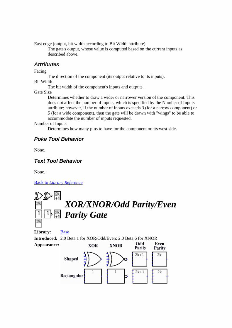
XOR/XNOR/Odd Parity/Even Parity Gate
Library: Base Introduced: 2.0 Beta 1 for XOR/Odd/Even; 2.0 Beta 6 for XNOR Appearance:

Behavior
The XOR, XNOR, Even Parity, and Odd Parity gates each compute the respective function of the inputs, and emit the result on the output. The two-input truth table for the gates is the following.
x y XOR XNOR Odd Even0 0 0 1 0 1 0 1 1 0 1 0 1 0 1 0 1 0 1 1 0 1 0 1
As you can see, the Odd Parity gate and the XOR gate behave identically with two inputs; similarly, the even parity gate and the XNOR gate behave identically. But if there are more than two specified inputs, the XOR gate will emit 1 only when there is exactly one 1 input, whereas the Odd Parity gate will emit 1 if there are an odd number of 1 inputs. The XNOR gate will emit 1 only when there is not exactly one 1 input, while the Even Parity gate will emit 1 if there are an even number of 1 inputs.
Any inputs that are unspecified (i.e., floating) are ignored. If all inputs are floating, then the output is floating, too. If any of the inputs are the error value (e.g., if conflicting values are coming into the same wire), then the output will be the error value, too.
The multi-bit versions of each gate will perform its one-bit transformation bitwise on its inputs.
Note: Many authorities contend that the shaped XOR gate's behavior should correspond to the odd parity gate, but there is not agreement on this point. Logisim's behavior for XOR gates is based on the IEEE 91 standard. It is also consistent with the intuitive meaning underlying the term exclusive or: A waiter asking whether you want a side dish of mashed potatoes, carrots, peas, or cole slaw will only accept one choice, not three, whatever some authorities may tell you. (I must admit, though, that I have not subjected this statement to a rigorous test.)
Pins West edge (inputs, bit width according to Bit Width attribute)
The inputs into the component. There will be as many of these as specified in the Number of Inputs attribute.
Note that if you are using shaped gates, the west side of XOR and XNOR gates will be curved. Nonetheless, the input pins are in a line. Logisim will draw short stubs illustrating this; and if you overshoot a stub, it will silently assume that you did not mean to overshoot it. In "printer view", these stubs will not be drawn unless they are connected to wires.
East edge (output, bit width according to Bit Width attribute)

The gate's output, whose value is computed based on the current inputs as described above.
Attributes Facing
The direction of the component (its output relative to its inputs). Bit Width
The bit width of the component's inputs and outputs. Gate Size
Determines whether to draw a wider or narrower version of the component. This does not affect the number of inputs, which is specified by the Number of Inputs attribute; however, if the number of inputs exceeds 3 (for a narrow component) or 5 (for a wide component), then the gate will be drawn with "wings" to be able to accommodate the number of inputs requested.
Number of Inputs Determines how many pins to have for the component on its west side.
Poke Tool Behavior
None.
Text Tool Behavior
None.
Back to Library Reference
Controlled Buffer/Inverter Library: Gates Introduced: 2.0 Beta 1 Appearance:
Behavior
The controlled buffer and inverter, often called three-state buffers/inverters, each have a one-bit "control" input pin on the south side. The value at this control pin affects how the component behaves:
• When the value on this pin is 1, then the component behaves just like the respective component (a buffer or a inverter (NOT gate)).
• When the value is 0 or unknown (i.e., floating), then the component's output is also floating.
• When the value is an error value (such as would occur when two conflicting values are being fed into the input), then the output is an error value.
Controlled buffers can be useful when you have a wire (often called a bus) whose value should match the output of one of several components. By placing a controlled buffer between each component output and the bus, you can control whether that component's output is fed onto the bus or not.
Pins Facing
The direction of the component (its output relative to its input). West edge (input, bit width matches Bit Width attribute)
The component input that will be used to compute the output if the control input is 1.
South edge (input, bit width 1) The component's control input.
East edge (output, bit width matches Bit Width attribute) The component's output, which will be floating if the control input is 0 or floating, the error value if the control input is the error value, and will be computed based on the west-side input if the control input is 1.
Attributes Bit Width
The bit width of the component's inputs and outputs.
Poke Tool Behavior
None.
Text Tool Behavior
None.
Back to Library Reference
Plexers library The Plexers library includes control components. Like the components of the Gates library, all are combinational, but their purpose is generally for routing values.
Multiplexer Demultiplexer Decoder Bit Selector

Back to Library Reference
Multiplexer Library: Plexers Introduced: 2.0 Beta 11 Appearance:
Behavior
Copies an input on the west edge onto the output on the east edge; which of the inputs to copy is specified via the current value received through the input on the south edge. I find it useful to think of a multiplexer as analogous to a railroad switch, controlled by the select input.
(Incidentally, some authorities spell this multiplexor, but multiplexer is the predominant spelling.)
Pins West edge, variable number (inputs, bit width matches Data Bits attribute)
Data values, one of which is to be routed to the output. Each input data value is numbered, starting with 0 on the north.
East edge (output, bit width matches Data Bits attribute) The output value will match the input values on the west edge whose number is the same as the value currently received through the select input on the south. If the select input contains any unspecified (i.e., floating) bits, then the output is completely floating.
South edge (input, bit width matches Select Bits attribute) Select input: The value of this input determines which input on the west edge to route to the output on the east edge.
Attributes Select Bits
The bit width of the component's select input on its south edge. The number of inputs to the multiplexer will be 2selectBits.
Data Bits The bit width of the data being routed through the multiplexer.
Poke Tool Behavior
None.

Text Tool Behavior
None.
Back to Library Reference
Demultiplexer Library: Plexers Introduced: 2.0 Beta 11 Appearance:
Behavior
Copies the input on the west edge onto exactly one of the outputs on the east edge; which of these outputs is specified via the current value received through the input on the south edge. I find it useful to think of a demultiplexer as analogous to a railroad switch, controlled by the select input.
(Incidentally, some authorities spell this demultiplexor, but demultiplexer is the predominant spelling.)
Pins West edge (input, bit width matches Data Bits attribute)
The value to be routed to one of the outputs on the east edge. East edge, variable number (outputs, bit width matches Data Bits attribute)
The outputs are numbered starting with 0 on the north. An output will match the west input if its number matches the value currently received through the select input on the south; otherwise, its value will be either all-zeroes or all-floating, depending on the value of the Three-State? attribute. If the select input contains any unspecified bits, then all outputs are floating.
South edge (input, bit width matches Select Bits attribute) Select input: The value of this input determines to which output on the east edge to route the value received on the west edge.
Attributes Select Bits
The bit width of the component's select input on its south edge. The number of outputs for the demultiplexer will be 2selectBits.
Data Bits The bit width of the data being routed through the demultiplexer.

Three-state? Specifies whether the unselected outputs should be floating (Yes) or zero (No).
Poke Tool Behavior
None.
Text Tool Behavior
None.
Back to Library Reference
Decoder Library: Plexers Introduced: 2.0 Beta 11 Appearance:
Behavior
Emits 1 on exactly one output; which output is 1 depends on the current value received through the input on the south edge.
Pins East edge, variable number (outputs, bit width 1)
The outputs are numbered starting with 0 on the north. Each output will be 1 if its number matches the value currently received through the select input on the south; otherwise, its value will be either zero or floating, depending on the value of the Three-State? attribute. If the select input contains any unspecified bits, then all outputs are floating.
South edge (input, bit width matches Select Bits attribute) Select input: The value of this input determines which of the outputs is 1.
Attributes Select Bits
The bit width of the component's select input on its south edge. The number of outputs for the decoder will be 2selectBits.
Three-state? Specifies whether the unselected outputs should be floating (Yes) or zero (No).
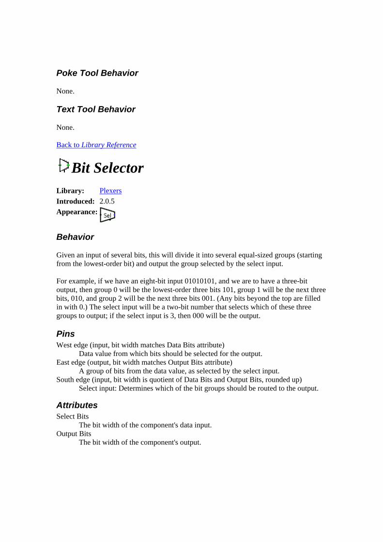
Poke Tool Behavior
None.
Text Tool Behavior
None.
Back to Library Reference
Bit Selector Library: Plexers Introduced: 2.0.5 Appearance:
Behavior
Given an input of several bits, this will divide it into several equal-sized groups (starting from the lowest-order bit) and output the group selected by the select input.
For example, if we have an eight-bit input 01010101, and we are to have a three-bit output, then group 0 will be the lowest-order three bits 101, group 1 will be the next three bits, 010, and group 2 will be the next three bits 001. (Any bits beyond the top are filled in with 0.) The select input will be a two-bit number that selects which of these three groups to output; if the select input is 3, then 000 will be the output.
Pins West edge (input, bit width matches Data Bits attribute)
Data value from which bits should be selected for the output. East edge (output, bit width matches Output Bits attribute)
A group of bits from the data value, as selected by the select input. South edge (input, bit width is quotient of Data Bits and Output Bits, rounded up)
Select input: Determines which of the bit groups should be routed to the output.
Attributes Select Bits
The bit width of the component's data input. Output Bits
The bit width of the component's output.
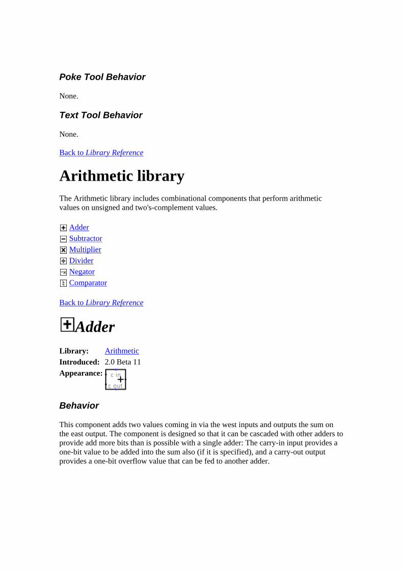
Poke Tool Behavior
None.
Text Tool Behavior
None.
Back to Library Reference
Arithmetic library The Arithmetic library includes combinational components that perform arithmetic values on unsigned and two's-complement values.
Adder Subtractor Multiplier Divider Negator Comparator
Back to Library Reference
Adder Library: Arithmetic Introduced: 2.0 Beta 11 Appearance:
Behavior
This component adds two values coming in via the west inputs and outputs the sum on the east output. The component is designed so that it can be cascaded with other adders to provide add more bits than is possible with a single adder: The carry-in input provides a one-bit value to be added into the sum also (if it is specified), and a carry-out output provides a one-bit overflow value that can be fed to another adder.

If either of the addends contains some floating bits or some error bits, then the component will perform a partial addition. That is, it will compute as many low-order bits as possible. But above the floating or error bit, the result will have floating or error bits.
Pins West edge, north end (input, bit width matches Bit Width attribute)
One of the two values to add. West edge, south end (input, bit width matches Bit Width attribute)
The other of the two values to add. North edge, labeled c in (input, bit width 1)
A carry value to add into the sum. If the value is unknown (i.e., floating), then it is assumed to be 0.
East edge (output, bit width matches Bit Width attribute) The lower bitWidth bits of the sum of the two values coming in the west edge, plus the cin bit.
South edge, labeled c out (output, bit width 1) The carry bit computed for the sum. If the values added together as unsigned values do not yield a result that fits into bitWidth bits, then this bit will be 0; otherwise, it will be 1.
Attributes Bit Width
The bit width of the values to be added and of the result.
Poke Tool Behavior
None.
Text Tool Behavior
None.
Back to Library Reference

Subtractor Library: Arithmetic Introduced: 2.0 Beta 11 Appearance:
Behavior
This component adds subtracts values coming in via the west inputs (the upper minus the lower) and outputs the difference on the east output. The component is designed so that it can be cascaded with other subtractors to provide subtract more bits than is possible with a single subtractor: The borrow-in input provides a one-bit value to be borrowed out of the difference (if the borrow-in input is specified), and a borrow-out output indicates whether the component needs to borrow an upper-order bit to complete the subtraction without underflow (assuming unsigned subtraction).
Internally, the subtractor simply performs a bitwise NOT on the subtrahend, and add this to the minuend along with the NOT of the borrow-in input. (The minuend is the first operand (upper input) to the subtraction, and the subtrahend is the second (lower input). I happen to like the antiquated terms.)
If either of the operands contains some floating bits or some error bits, then the component will perform a partial subtraction. That is, it will compute as many low-order bits as possible. But above the floating or error bit, the result will have floating or error bits.
Pins West edge, north end (input, bit width matches Bit Width attribute)
The minuend of the subtraction; that is, the number from which to subtract. West edge, south end (input, bit width matches Bit Width attribute)
The subtrahend of the subtraction; that is, the number to subtract from the minuend.
North edge, labeled b in (input, bit width 1) If 1, then 1 is borrowed out of the difference. If the value is unknown (i.e., floating), then it is assumed to be 0.
East edge (output, bit width matches Bit Width attribute) The lower bitWidth bits of the difference of the two values coming in the west edge, minus the bin bit.
South edge, labeled b out (output, bit width 1) The borrow bit computed for the difference. If the values subtracted as unsigned values yield a negative value, then this bit will be 1; otherwise, it will be 0.

Attributes Bit Width
The bit width of the values to be subtracted and of the result.
Poke Tool Behavior
None.
Text Tool Behavior
None.
Back to Library Reference
Multiplier Library: Arithmetic Introduced: 2.0 Beta 20 Appearance:
Behavior
This component multiplies two values coming in via the west inputs and outputs the product on the east output. The component is designed so that it can be cascaded with other multipliers to multiply a multiplicand with more bits than is possible with a single multiplier: The carry-in input provides a multi-bit value to be added into the product (if it is specified), and a carry-out output provides the upper half of the product result, which can be fed into another multiplier.
If the multiplicand, the multiplier, or the carry-in input contain some floating bits or some error bits, then the component will perform a partial multiplication. That is, it will compute as many low-order bits as possible. But above the floating or error bit, the result will have floating or error bits. Note that if the carry-in input is completely floating, then it will be assumed to be all-zeroes.
Pins West edge, north end (input, bit width matches Bit Width attribute)
The multiplicand (that is, the first of the two numbers to multiply). West edge, south end (input, bit width matches Bit Width attribute)
The multiplier (that is, the second of the two numbers to multiply).
North edge, labeled c in (input, bit width matches Bit Width attribute) A carry value to add into the product. If all bits of the value are unknown (i.e., floating), then they are assumed to be 0.
East edge (output, bit width matches Bit Width attribute) The lower bitWidth bits of the product of the two values coming in the west edge, plus the cin value.
South edge, labeled c out (output, bit width 1) The upper bitWidth bits of the product.
Attributes Bit Width
The bit width of the values to be multiplied and of the result.
Poke Tool Behavior
None.
Text Tool Behavior
None.
Back to Library Reference
Divider Library: Arithmetic Introduced: 2.0 Beta 22 Appearance:
Behavior
This component divides two values coming in via the west inputs and outputs the quotient on the east output. The component is designed so that it can be cascaded with other dividers to provide support a dividend with more bits than is possible with a single divider: The upper input provides the upper bitWidth bits of the dividend (if it is specified at all), and the rem bits provide the remainder, which can be fed as the upper input into another divider.
If the divisor is 0, then no division is performed (i.e., the divisor is assumed to be 1).
The divider essentially performs unsigned division. That is, the remainder will always be between 0 and divisor-1. The quotient will always be an integer so that

quotient * divisor + remainder = dividend . If, however, the quotient does not fit into bitWidth bits, then only the lower bitWidth bits will be reported. The component does not provide any method for accessing the upper bitWidth bits.
If either of the operands contains some floating bits or some error bits, then the component's outputs will be either entirely floating or entirely error values.
Pins West edge, north end (input, bit width matches Bit Width attribute)
The lower bitWidth bits of the dividend (that is, the first operand for the division). West edge, south end (input, bit width matches Bit Width attribute)
The divisor (that is, the second operand for the division) North edge, labeled upper (input, bit width matches Bit Width attribute)
The upper bitWidth bits of the dividend (that is, the first operand for the division). East edge (output, bit width matches Bit Width attribute)
The lower bitWidth bits of the quotient, as specified above. South edge, labeled rem (output, bit width 1)
The remainder of the division. This value will always be between 0 and divisor-1.
Attributes Bit Width
The bit width of the values to be divided and of the result.
Poke Tool Behavior
None.
Text Tool Behavior
None.
Back to Library Reference
Negator Library: Arithmetic Introduced: 2.0 Beta 22 Appearance:
Behavior
Computes the two's-complement negation of the input. This negation is performed by maintaining all the lower-order bits up to the lowest-order 1, and complementing all bits above that.
If the value to be negated happens to be the least negative value, then its negation (which cannot be represented in two's-complement form), is still the least negative value.
Pins West edge (input, bit width matches Bit Width attribute)
The value to negate. East edge, labeled -x (output, bit width matches Bit Width attribute)
The negation of the input. If the input happens to be the least negative value representable in bitWidth bits, however, then the output matches the input.
Attributes Bit Width
The bit width of the component's input and output.
Poke Tool Behavior
None.
Text Tool Behavior
None.
Back to Library Reference

Comparator Library: Arithmetic Introduced: 2.0 Beta 22 Appearance:
Behavior
Compares two values, either as unsigned values or as two's-complement values, depending on the Numeric Type attribute. Normally, one of the outputs will be 1, and the other two outputs will be 0.
The comparison is performed starting at the most significant bits in each number and descending downward in parallel until a location is found where the two values disagree. If, however, an error value or a floating value is encountered during this descent, then all outputs will match that error or floating value.
Pins West edge, north end (input, bit width matches Bit Width attribute)
The first of the two values to be compared. West edge, south end (input, bit width matches Bit Width attribute)
The second of the two values to be compared. East edge, labeled > (output, bit width 1)
1 if the first input is greater than the second input, 0 if the first input is less than or equal the second input.
East edge, labeled = (output, bit width 1) 1 if the first input equals the second input, 0 if the first input is not equal the second input.
East edge, labeled < (output, bit width 1) 1 if the first input is less than the second input, 0 if the first input is greater than or equal the second input.
Attributes Bit Width
The bit width of the component's inputs and outputs.
Poke Tool Behavior
None.

Text Tool Behavior
None.
Back to Library Reference
Legacy library The Legacy library includes components that exist only for backward compatibility with versions of Logisim in the 1.0x series.
Logisim 1.0 D/J-K Flip-Flop Logisim 1.0 8-Bit Register
Back to Library Reference
Logisim 1.0 D/J-K Flip-Flop Library: Legacy Introduced: 2.0 Beta 12 Appearance:
Behavior
The reason for this component is for backwards compatibility with Logisim 1.0X; for new circuits, the Memory library's flip-flops are recommended instead.
Each flip-flop stores a single bit of data, which is emitted through the Q output on the east side. Normally, the value can be controlled via the inputs to the west side. In particular, the value changes when the clock input, marked by a triangle on each flip-flop, rises from 0 to 1; on this rising edge, the value changes according to the corresponding table below.
D Flip-Flop J-K Flip-FlopD Q0 01 1
J K Q0 0 Q0 1 01 0 11 1 Q'
Another way of describing the different behavior of the flip-flops is in English text.

• D Flip-Flop: When the clock rises from 0 to 1, the value remembered by the flip-flop becomes the value of the D input (Data) at that instant.
• J-K Flip-Flop: When the clock rises from 0 to 1, the value remembered by the flip-flop toggles if the J and K inputs are both 1, remains the same if they are both 0, and changes to the K input value if J and K are not equal. (The names J and K do not stand for anything.)
Pins West edge, marked by triangle (input, bit width 1)
Clock input: At the instant that this input value switches from 0 to 1 (the rising edge), the value will be updated according to the other inputs on the west edge. As long as this remains 0 or 1, the other inputs on the west edge have no effect.
West edge, other labeled input(s) (input(s), bit width 1) These inputs control how the flip-flop's value changes during the rising edge of the clock. Their exact behavior depends on the flip-flop; the above tables summarize their behavior.
East edge, labeled Q, north end (output, bit width 1) Outputs the value currently stored by the flip-flop.
East edge, south end (output, bit width 1) Outputs the complement of the value currently stored by the flip-flop.
Attributes
None.
Poke Tool Behavior
Clicking a flip-flop using the Poke Tool toggles the bit stored in the flip-flop, unless the asynchronous set/reset inputs currently pin the flip-flop's value.
Text Tool Behavior
None.
Back to Library Reference

Logisim 1.0 8-Bit Register Library: Legacy Introduced: 2.0 Beta 12 Appearance:
Behavior
The reason for this component is for backwards compatibility with Logisim 1.0X; for new circuits, the Memory library's register is recommended instead.
The register stores a single 8-bit value, which is displayed in hexadecimal within its rectangle, and is emitted via its outputs on its east edge. (Logisim 1.0X did not support multi-bit values, so the register had to have a pin for each individual bit.) At the instant when the clock input (indicated by a triangle on the west edge) rises from 0 to 1, the value stored in the register changes to the value specified through the eight other bits on the west edge.
Pins East edge, eight pins (outputs, bit width 1 each)
Outputs the value currently stored by the register, with the lowest-order bit at the northmost pin.
West edge, eight pins (inputs, bit width 1 each) At the instant that the clock value rises from 0 to 1, the register's value changes to the value of the inputs at that instant. The lowest-order bit is at the northmost pin.
West edge, indicated with a triangle (input, bit width 1) Clock input: At the instant that this input value rises from 0 to 1 (the rising edge), the register's value will be updated to the values of the other inputs on the west edge.
Attributes
None.
Poke Tool Behavior
Clicking the register brings keyboard focus to the register (indicated by a red rectangle), and typing hexadecimal digits will change the value stored in the register.

Text Tool Behavior
None.
Back to Library Reference
Memory library The Memory library includes components that remember information.
D/T/J-K/S-R Flip-Flop Register RAM ROM
D/T/J-K/S-R Flip-Flop Library: Memory Introduced: 2.0 Beta 1 Appearance:
Behavior
Each flip-flop stores a single bit of data, which is emitted through the Q output on the east side. Normally, the value can be controlled via the inputs to the west side. In particular, the value changes when the clock input, marked by a triangle on each flip-flop, rises from 0 to 1; on this rising edge, the value changes according to the corresponding table below.
D Flip-Flop T Flip-Flop J-K Flip-Flop S-R Flip-Flop D Q 0 0 1 1
T Q0 Q1 Q'
J K Q0 0 Q0 1 01 0 11 1 Q'
S R Q0 0 Q0 1 01 0 11 1 ??
Another way of describing the different behavior of the flip-flops is in English text.

• D Flip-Flop: When the clock rises from 0 to 1, the value remembered by the flip-flop becomes the value of the D input (Data) at that instant.
• T Flip-Flop: When the clock rises from 0 to 1, the value remembered by the flip-flop either toggles or remains the same depending on whether the T input (Toggle) is 1 or 0.
• J-K Flip-Flop: When the clock rises from 0 to 1, the value remembered by the flip-flop toggles if the J and K inputs are both 1, remains the same if they are both 0, and changes to the K input value if J and K are not equal. (The names J and K do not stand for anything.)
• R-S Flip-Flop: When the clock rises from 0 to 1, the value remembered by the flip-flop remains unchanged if R and S are both 0, becomes 0 if the R input (Reset) is 1, and becomes 1 if the S input (Set) is 1. The behavior in unspecified if both inputs are 1. (In Logisim, the value in the flip-flop remains unchanged.)
Pins West edge, marked by triangle (input, bit width 1)
Clock input: At the instant that this input value switches from 0 to 1 (the rising edge), the value will be updated according to the other inputs on the west edge. As long as this remains 0 or 1, the other inputs on the west edge have no effect.
West edge, other labeled input(s) (input(s), bit width 1) These inputs control how the flip-flop's value changes during the rising edge of the clock. Their exact behavior depends on the flip-flop; the above tables summarize their behavior.
East edge, labeled Q, north end (output, bit width 1) Outputs the value currently stored by the flip-flop.
East edge, south end (output, bit width 1) Outputs the complement of the value currently stored by the flip-flop.
South edge, east end (input, bit width 1) Asynchronous reset: When 0 or undefined, this input has no effect. As long as it is 1, the flip-flop's value is pinned to 0. This occurs asynchronously - that is, without regard to the current clock input value. As long as this is 1, the other inputs have no effect.
South edge, west end (input, bit width 1) Asynchronous set: When 1 or undefined, this input has no effect. When 1, the flip-flop's value is pinned to 1. This occurs asynchronously - that is, without regard to the current clock input value. As long as this input is 1, the other inputs have no effect, except for the asynchronous reset input, which has priority.
Attributes
None.
Poke Tool Behavior
Clicking a flip-flop using the Poke Tool toggles the bit stored in the flip-flop, unless the asynchronous set/reset inputs currently pin the flip-flop's value.
Text Tool Behavior
None.
Back to Library Reference
Register Library: Memory Introduced: 2.0 Beta 1 Appearance:
Behavior
A register stores a single multi-bit value, which is displayed in hexadecimal within its rectangle, and is emitted on its Q output. At the instant when the clock input (indicated by a triangle on the south edge) rises from 0 to 1, the value stored in the register changes to the value of the D input at that instant.
The clr input resets the register's value to 0 (all zeroes) asynchronously; that is, as long as the clr input is 1, the value is pinned to 0, regardless of the clock input.
Pins East edge, labeled Q (output, bit width matches Data Bit Width attribute)
Outputs the value currently stored by the register. West edge, labeled D (input, bit width matches Data Bit Width attribute)
Data input: At the instant that the clock value rises from 0 to 1, the register's value changes to the value of the D input at that instant.
South edge, indicated with a triangle (input, bit width 1) Clock input: At the instant that this input value rises from 0 to 1 (the rising edge), the register's value will be updated to the value of the D input.
South edge, labeled clr (input, bit width 1) Asynchronous reset: When 0 or undefined, this input has no effect. As long as it is 1, the register's value is pinned to 0. This occurs asynchronously - that is, without regard to the current clock input value. As long as this is 1, the other inputs have no effect.
Attributes Data Bit Width
The bit width of the value stored in the register.
Poke Tool Behavior
Clicking the register brings keyboard focus to the register (indicated by a red rectangle), and typing hexadecimal digits will change the value stored in the register.
Text Tool Behavior
None.
RAM
Library: Memory Introduced: 2.0 Beta 1 Appearance:
Behavior The RAM component, easily the most complex component in Logisim's built-in libraries, stores up to 4,096 values (specified in the Address Bit Width attribute), each of which can include up to to 32 bits (specified in the Data Bit Width attribute). The circuit can load and store values in RAM. Also, the user can modify individual values interactively via the Poke Tool, or the user can modify the entire contents via the Menu Tool.
Current values are displayed in the component. Addresses displayed are listed in gray to the left of the display area. Inside, each value is listed using hexadecimal. The value at the currently selected address will be displayed in inverse text (white on black).
Pins A on west edge (input, bit width matches Address Bit Width attribute)
Selects which of the values are currently being accessed by the circuit.

D on east edge (input/output, bit width matches Data Bit Width attribute)
If out is 1 or undefined (i.e, floating), then the RAM outputs the value at the currently selected address at the D pin. (A zero on sel with disable this.) If out is 0, then the D pin is an input, as a value that will be placed at the currently selected address once the clock rises from 0 to 1.
sel on south edge (input, bit width 1)
If you have just one RAM module, ignore this input. If you have multiple RAM modules in parallel, you can use this input to enable or disable the entire RAM module, based on whether the value is 1 or 0. In other words, when this is 0, no value is emitted on the D output, and the values in memory will not change when the clock rises from 0 to 1.
triangle on south edge (input, bit width 1)
Clock input: When out is 0, and this input rises from 0 to 1 (and sel is 1/undefined and clr is 0), then the value at the currently selected address changes to whatever value is at the D pin. As long as the clock input remains 0 or 1, though, the D value will not be stored into memory.
out on south edge (input, bit width 1)
Selects whether the RAM should emit (on D) the value at the current address (A). This output behavior is enabled if out is 1 or undefined; if out is 0, then D behaves as an input for writing a value once the clock rises from 0 to 1.
clr on south edge (input, bit width 1)
When this is 1, and sel is 1 or undefined, all values in memory are pinned to 0, no matter what the other inputs are.
Attributes Address Bit Width
The bit width of the address bits. The number of values stored in RAM is 2addrBitWidth.
Data Bit Width
The bit width of each individual value in memory.
Poke Tool Behavior See poking memory in the User's Guide.

Text Tool Behavior None.
Menu Tool Behavior See pop-up menus and files in the User's Guide.
ROM Library: Memory Introduced: 2.1.0 Appearance:
Behavior The ROM component stores up to 4,096 values (specified in the Address Bit Width attribute), each of which can include up to to 32 bits (specified in the Data Bit Width attribute). A circuit can access the current values in ROM, but it cannot change them. The user can modify individual values interactively via the Poke Tool, or the user can modify the entire contents via the Menu Tool.
Unlike the RAM component, the ROM component's current contents are stored as an attribute of the component. Thus, if a circuit containing a ROM component is used twice, then both ROM components will hold the same values. Also because of this behavior, the current ROM contents are stored in files created by Logisim.
Current values are displayed in the component. Addresses displayed are listed in gray to the left of the display area. Inside, each value is listed using hexadecimal. The value at the currently selected address will be displayed in inverse text (white on black).
Pins A on west edge (input, bit width matches Address Bit Width attribute)
Selects which of the values are currently being accessed by the circuit.

D on east edge (input/output, bit width matches Data Bit Width attribute)
Outputs the value at the currently selected address at the D pin if sel is 1 or floating. If sel is 0, then D will be floating.
sel on south edge (input, bit width 1)
If you have just one ROM module, ignore this input. If you have multiple ROM modules in parallel, you can use this input to enable or disable the entire ROM module, based on whether the value is 1 or 0. In other words, when this is 0, no value is emitted on the D output.
Attributes Address Bit Width
The bit width of the address bits. The number of values stored in RAM is 2addrBitWidth.
Data Bit Width
The bit width of each individual value in memory.
Contents
Stores the contents of memory.
Poke Tool Behavior See poking memory in the User's Guide.
Text Tool Behavior None.
Menu Tool Behavior See pop-up menus and files in the User's Guide.

Memory components The RAM and ROM components are two of the more useful components in Logisim's built-in libraries. However, because of the volume of information they can store, they are also two of the most complex components.
Documentation about how they work within a circuit can be found on the RAM and ROM pages of the Library Reference. This section of the User's Guide explains the interface allowing the user to view and edit memory contents.
Poking memory Pop-up menus and files
Next: Poking memory.
Poking memory You can manipulate the contents of memory using the Poke Tool, but the interface for this is severely limited by space constraints: For more than the simplest editing, you will probably find the integrated hex editor far more convenient.
Nonetheless, to view and edit values within the circuit, the Poke Tool has two modes of operation: You can edit the address displayed, and you can edit an individual value.
To edit the address displayed, click outside the display rectangle. Logisim will draw a red rectangle around the top address.
• Typing hexadecimal digits will change the top address accordingly. • Typing the Enter key will scroll down one line. • Typing the Backspace key will scroll up one line. • Typing the space bar will scroll down one page (four lines).
To edit a particular value, click the value within the display rectangle. Logisim will draw a red rectangle around that address.
• Typing hexadecimal digits will change the value at the address currently being edited.
• Typing the Enter key will move to editing the value just below it in the display (down one line).
• Typing the Backspace key will move to editing the value at the previous address. • Typing the space bar will move to editing the value at the following address.
Next: Pop-up menus and files.

Pop-up menus and files The pop-up menu for memory includes four options in addition to the options common to all components:
• Edit Contents: Bring up a hex editor for editing the contents of memory. • Clear Contents: Resets all values in memory to 0. • Load Image...: Resets all values in memory based on the values found in a file
using the format described below. • Save Image...: Stores all values in memory into a file using the format described
below.
The file format used for image files is intentionally simple; this permits you to write a program, such as an assembler, that generates memory images that can then be loaded into memory. As an example of this file format, if we had a 256-byte memory whose first five bytes were 2, 3, 0, 20, and -1, and all subsequent values were 0, then the image would be the following text file.
v2.0 raw 02 03 00 14 ff The first line identifies the file format used (currently, there is only one file format recognized). Subsequent values list the values in hexadecimal, starting from address 0; you can place several such values on the same line. Logisim will assume that any values unlisted in the file are zero.
The image file can use run-length encoding; for example, rather than list the value 00 sixteen times in a row, the file can include 16*00 rather than repeat 00 sixteen times. Notice than the number of repetitions is written in base 10. Files produced by Logisim will use run-length encoding for runs of at least four values.
Next: Hex editor.
Hex editor Logisim includes an integrated hex editor for viewing and editing the contents of memory. To access it, bring up a pop-menu for the memory component and select Edit Contents.... For ROM components, which have the memory contents as part of the attribute value, you can alternatively access the hex editor by clicking the corresponding attribute value.

The numbers in italics at left display memory addresses, written in hexadecimal. The other numbers display values starting from that memory address; the hex editor may display four, eight, or sixteen values per line, depending on what fits in the window. To help with counting, each group of four values has a larger space between.
You can navigate through memory using the scroll bar or using the keyboard (the arrow keys, home, end, page up, and page down). Typing hexadecimal characters will alter the currently selected value.
You can select a range of values by dragging the mouse, shift-clicking the mouse, or navigating through memory with the keyboard while depressing the shift key. Values may be copied and pasted using the Edit menu; the clipboard can also be transferred into other applications.
Next: User's Guide.
Logging In testing a large circuit, and for documenting a circuit's behavior, a log of past circuit behavior. This is the purpose for Logisim's logging module, which allows you to select components whose values should be logged; optionally, you can specify a file into which the log should be placed.
Note: The logging module is in alpha phase; it may be buggy, and it is subject to significant changes in the future. While bug reports and suggestions are welcome for all of Logisim, they are particularly welcome concerning this relatively new feature. If you do not send comments, then it will likely not change.
You can enter the logging module via the Logging... option from the Simulate menu. It brings up a window with three tabs.

We will discuss each of these tabs separately. The Selection tab The Table tab The File tab
Each project has only one logging window; when you switch to viewing another circuit within the project, the logging window switches automatically to logging the other circuit instead. That is, it does this unless you are moving up or down within the same simulation, in which case the logging module does not change.
Note that when the logging module switches to logging another simulation, it will cease any logging into a file. Should you switch back to the simulation again, it will remember the configuration for that simulation, but you will need to re-enable the file logging manually.
Next: The Selection tab.
The Selection tab The Selection tab allows you to select which values should be included in the log. The window below corresponds to the following circuit.

The tab is divided into three vertical areas. The first (leftmost) is a list of all components in the circuit whose values can be logged. Among the built-in libraries, the following types of components support logging.
Base library: Pin, Probe, and Clock components Memory library: All components For components with labels associated with them, their names correspond to the labels; other components' names specify their type and their location within the circuit. Any subcircuits will also appear in the list; they cannot be selected for logging, but eligible components within them can be. Note that the RAM component requires you to choose which memory address(es) should be logged; it allows logging only for the first 256 addresses.
The last (rightmost) vertical area lists those components that have been selected. Also, it indicates the radix (base) in which the component's multi-bit values will be logged; the radix does not have a significant effect on one-bit values.
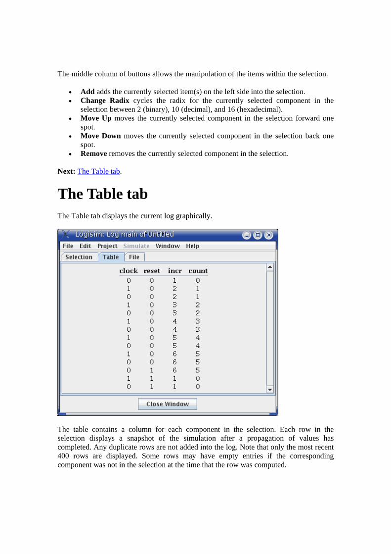
The middle column of buttons allows the manipulation of the items within the selection.
• Add adds the currently selected item(s) on the left side into the selection. • Change Radix cycles the radix for the currently selected component in the
selection between 2 (binary), 10 (decimal), and 16 (hexadecimal). • Move Up moves the currently selected component in the selection forward one
spot. • Move Down moves the currently selected component in the selection back one
spot. • Remove removes the currently selected component in the selection.
Next: The Table tab.
The Table tab The Table tab displays the current log graphically.
The table contains a column for each component in the selection. Each row in the selection displays a snapshot of the simulation after a propagation of values has completed. Any duplicate rows are not added into the log. Note that only the most recent 400 rows are displayed. Some rows may have empty entries if the corresponding component was not in the selection at the time that the row was computed.

The displayed table is for review only; it is not interactive.
Next: The File tab.
The File tab The File tab allows you to specify a file into which the log should be placed.
At the top is an indicator of whether file logging is in progress and a button for enabling or disabling it. (Note that you cannot enable it until a file is selected below.) The button allows you to pause and restart file entry. When you switch in the project window to viewing another simulation, the file logging is automatically halted; if you return to the original one and want logging to continue, you will need to re-enable the file logging manually using the button at top.
In the middle is an indicator of what file is being logged to. To change it, use the Select... button. On selecting a file, file logging will automatically start. If you select a pre-existing file, Logisim will ask whether you want to overwrite the file or append the new entries onto the end.
At bottom you can control whether a header line should be placed into the file indicating which items are in the selection. If header lines are added, then a new header line will be placed into the file whenever the selection changes.

File format
Entries are placed into the file in tab-delimited format corresponding closely to what appears under the Table tab. (One difference is that any header lines will give the full path to components lying in subcircuits.) The format is intentionally simple so that you can feed it into another program for processing, such as a Python/Perl script or a spreadsheet program.
So that a script can process the file at the same time as Logisim is running, Logisim will flush the new records onto the disk every 500 ms. Note that Logisim may also intermittently close and later re-open the file during the simulation, particularly if several seconds have elapsed without any new records being added.
.
Application Preferences Logisim supports two categories of configuration options: application preferences and project options. The application preferences address preferences that span all open projects, whereas project options are specific to that one project. This section discusses application preferences; project options are described in another section.
You can view and edit application preferences via the Preferences... option from the File menu (or, under Mac OS, the Logisim menu), a window will appear with two tabs. We will discuss these two tabs separately, and then we will see how preferences can be configured from the command line.
The Template tab The International tab The command line
Next: The Template tab.

The Template tab
A template is a Logisim file that is used as a starting point whenever Logisim creates a new project. Also, if you have an existing Logisim file with a strangely configured environment, you can ``reset'' the environment using the Revert All To Template button in the window for editing Project Options.
Although templates are useful in other situations also, they are particularly suited for classroom use, where an instructor might want to distribute a template for students to start from. This is particularly likely if the class uses Logisim heavily, including many of the more advanced features, in which case the simple default configuration may prove too simple. Templates can also be useful in the classroom setting when the instructor opens a file submitted by a student who has configured the environment significantly.
By default, the ``Plain Template'' option will be selected, using the default template shipped with Logisim. If you want a bare-bones configuration, you might choose ``Empty Template.'' But if you want to designate another file to use as the template, select a template via the Select... button, and then choose the ``Custom Template'' option.
Next: The International tab.

The International tab These preferences support options allowing Logisim to be used in many countries.
The tab includes three options.
• Language: Change between languages. The current version is supplied with both an English translation and a Spanish translation. The Spanish translation has been contributed by Pablo Leal Ramos, from Spain.
I welcome translations of Logisim into other languages! If you are interested, contact me, Carl Burch. This will not be a commitment: I will be happy to hear of your interest, and I will tell you whether I know of somebody who is working on it already, prepare a version for you to work with, and send you instructions. The translation process does not require an understanding of Java.
• Replace Accented Characters: Some platforms have poor support for characters (such as ñ or ö) that do not appear in the 7-bit ASCII character set. When this is checked, Logisim will replace all instances of the characters with the appropriate equivalent 7-bit ASCII characters. The checkbox is disabled when the current language does not have any equivalents available (as with English).
• Shaped Gates: There are two major standards for drawing logic gates: shaped gates and rectangular gates. The following table illustrates the distinction.
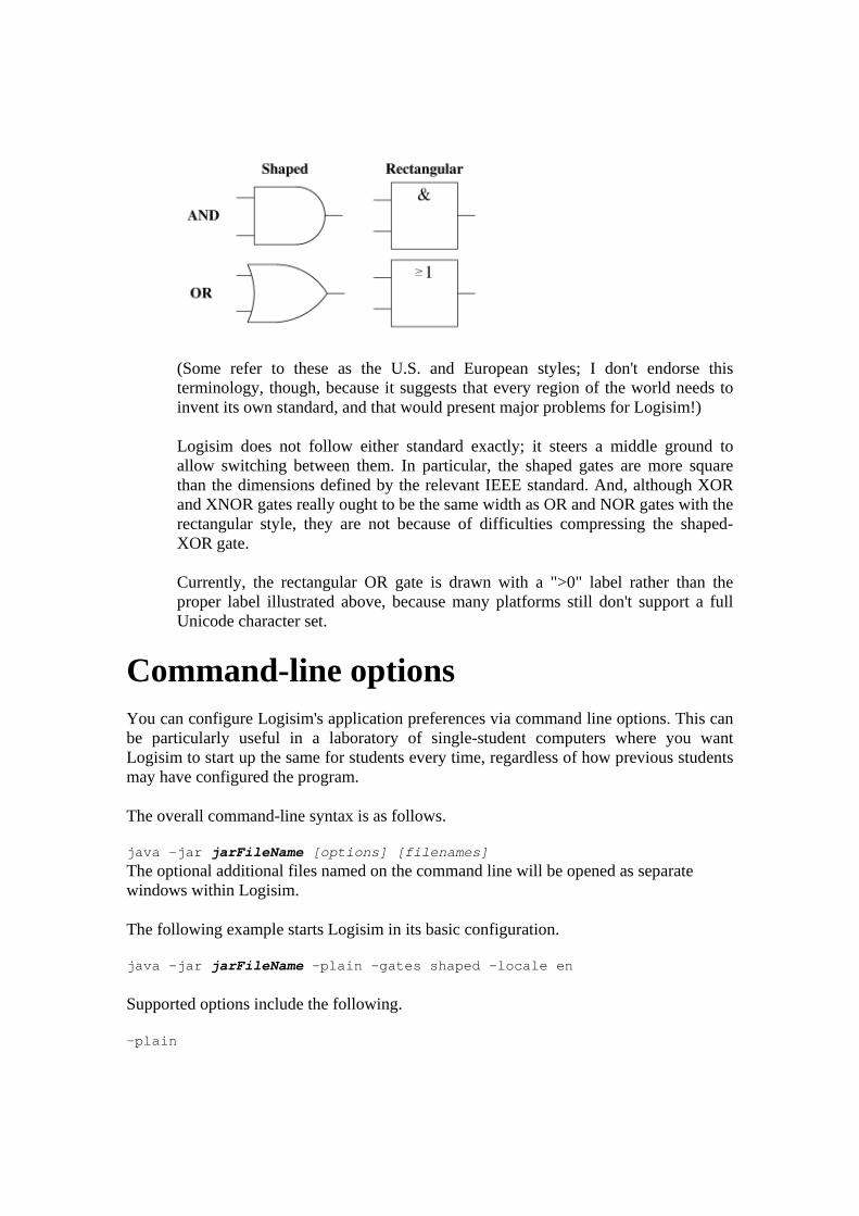
(Some refer to these as the U.S. and European styles; I don't endorse this terminology, though, because it suggests that every region of the world needs to invent its own standard, and that would present major problems for Logisim!)
Logisim does not follow either standard exactly; it steers a middle ground to allow switching between them. In particular, the shaped gates are more square than the dimensions defined by the relevant IEEE standard. And, although XOR and XNOR gates really ought to be the same width as OR and NOR gates with the rectangular style, they are not because of difficulties compressing the shaped-XOR gate.
Currently, the rectangular OR gate is drawn with a ">0" label rather than the proper label illustrated above, because many platforms still don't support a full Unicode character set.
Command-line options You can configure Logisim's application preferences via command line options. This can be particularly useful in a laboratory of single-student computers where you want Logisim to start up the same for students every time, regardless of how previous students may have configured the program.
The overall command-line syntax is as follows.
java -jar jarFileName [options] [filenames] The optional additional files named on the command line will be opened as separate windows within Logisim.
The following example starts Logisim in its basic configuration.
java -jar jarFileName -plain -gates shaped -locale en
Supported options include the following.
-plain

-empty -template templateFile
Configures the template for Logisim to use. -gates [shaped|rectangular]
Configures which type of gate to use. -locale localeIdentifier
Configures which translation to use. As of this writing, the supported locales include:
en Englishes Spanish
-accents [yes|no] This is only relevant for languages that use characters outside the 7-bit ASCII character set; this would include languages using accented characters, and it would not include English. If no, characters outside the 7-bit ASCII character set are replaced with equivalents appropriate to the language; this would be useful for Java/OS combinations where such characters are not supported well.
-nosplash Hides the initial Logisim splash screen.
-help Displays a summary of the command line options.
-version Displays the Logisim version number.
Next: User's Guide.
Project Options Logisim supports two categories of configuration options: application preferences and project options. The application preferences address preferences that span all open projects, whereas project options are specific to that one project. This section discusses project options; application preferences are described in another section.
You can view and edit project options via the Options... option from the Project menu. It brings up the Options window, which has four tabs.
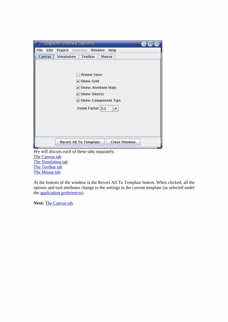
We will discuss each of these tabs separately. The Canvas tab The Simulation tab The Toolbar tab The Mouse tab
At the bottom of the window is the Revert All To Template button. When clicked, all the options and tool attributes change to the settings in the current template (as selected under the application preferences).
Next: The Canvas tab.
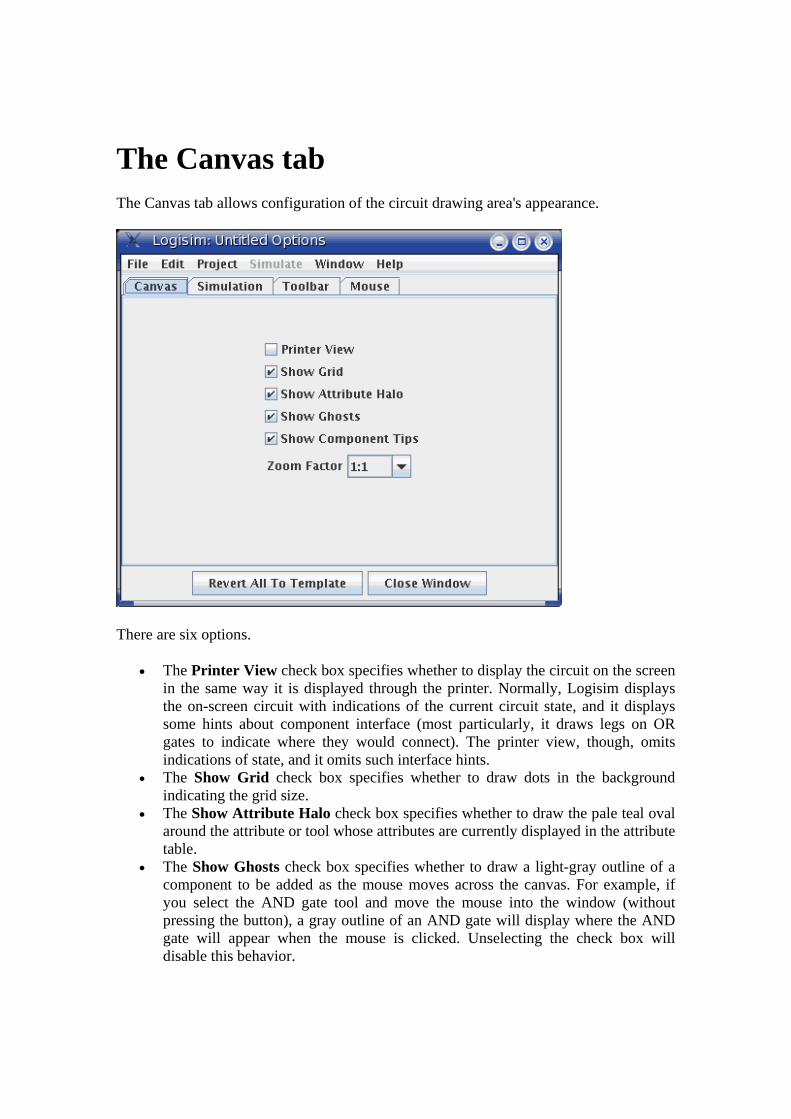
The Canvas tab The Canvas tab allows configuration of the circuit drawing area's appearance.
There are six options.
• The Printer View check box specifies whether to display the circuit on the screen in the same way it is displayed through the printer. Normally, Logisim displays the on-screen circuit with indications of the current circuit state, and it displays some hints about component interface (most particularly, it draws legs on OR gates to indicate where they would connect). The printer view, though, omits indications of state, and it omits such interface hints.
• The Show Grid check box specifies whether to draw dots in the background indicating the grid size.
• The Show Attribute Halo check box specifies whether to draw the pale teal oval around the attribute or tool whose attributes are currently displayed in the attribute table.
• The Show Ghosts check box specifies whether to draw a light-gray outline of a component to be added as the mouse moves across the canvas. For example, if you select the AND gate tool and move the mouse into the window (without pressing the button), a gray outline of an AND gate will display where the AND gate will appear when the mouse is clicked. Unselecting the check box will disable this behavior.

• The Show Component Tips check box specifies whether to display the "tool tips" that will temporarily appear when the mouse hovers components supporting them. For example, if you hover over a subcircuit component's pin, it will display the label of the corresponding pin within the subcircuit - or it will display the subcircuit's name it has no label. Hovering over one of the ends of a splitter will tell you the bits to which that end corresponds. In addition, all components in the Memory and Plexers libraries will provide information about their inputs and outputs via tips.
• The Zoom Factor allows you to ``blow up'' the image by a ratio. This option is mostly intended for live classroom demonstrations where the screen resolution is too small to view the circuit from the back of the classroom.
Next: The Simulation tab.
The Simulation tab The Simulation tab allows configuration of the algorithm used for simulating circuits. These parameters apply to all circuits being simulated in the same window, even for circuits that exist in other libraries loaded within the project.
• The Add Noise To Component Delays check box allows you to enable or disable the random noise that is added to the delays of components. The internal simulation uses a hidden clock for its simulation, and to provide a somewhat

realistic simulation, each component (excluding wires and splitters) has a delay between when it receives an input and when it emits an output. If this option is enabled, Logisim will occassionally (about once every 16 component reactions) make a component take one click longer than normal. This randomness is added specifically for handling latch circuit (as below): Without the random noise, the circuit oscillates, since the two gates will work in lockstep; but with random noise added, one gate will eventually outrun the other.
I recommend keeping this option on. The option exists in case you want deterministic circuit behavior. (Also, the random noise feature is relatively new to Logisim, and it could possibly lead to unanticipated bugs in the simulation.)
• The Iterations Until Oscillation combo box specifies how long to simulate a circuit before deciding that it is oscillating. The number represents the number of clicks of the internal hidden clock (a simple gate takes just one click). The default of 1,000 is good enough for almost all purposes, even for large circuits. But you may want to increase the number of iterations if you are working with a circuit where Logisim reports false oscillations; I can imagine problems with a circuit that incorporates many of the above latch circuits causing such a problem. You may want to decrease the number of iterations if you are working with a circuit that in prone to oscillating and you are using an unusually slow processor.
Next: The Toolbar tab.

The Toolbar tab The Toolbar tab allows you to configure what tools appear in the toolbar.
The left side is an explorer listing all the tools available, and the list on the right side displays the current contents of the toolbar. (A ``---'' indicates a separator, which appears as a small empty space.) Between the explorer and the list are five buttons:
• Add Tool adds the currently selected tool in the explorer at left to the end of the toolbar.
• Add Separator adds a separator to the end of the toolbar. • Move Up moves the currently selected item of the toolbar up/left one spot. • Move Down moves the currently selected item of the toolbar down/right one spot. • Remove removes the currently selected item from the toolbar.
The attributes associated with the tools are not displayed in this window; instead, you can view and edit them within the main drawing window.
Next: The Mouse tab.

The Mouse tab By default, when you click the mouse in Logisim's drawing area, the currently selected tool will be used. If you right-click or control-click, it will display a pop-up menu for the current component below the mouse.
Logisim allows you to modify this behavior, relieving you of the need to go to the toolbar and/or the explorer all the time. (This may also be handy if you are left-handed.) Each combination of a mouse button and a modifier key (shift and/or control) can be mapped to a different tool. The Mouse tab allows you to configure these mappings.
• On the left side is an explorer where you can choose the tool you want to map. • On the right top side is a rectangle in which you can click using the mouse
combination you want to click. For example, if you want to create new wires by shift-dragging, then you would first select the Wiring Tool in the Explorer (under the Base library); and then you would shift-click where it says ``Click Using Combination To Map Wiring Tool.'' If that combination is already being used, then the mapping would be replaced with the new tool.
• Below this area is a list of current mappings. Note that any combinations that aren't listed simply use the currently selected tool.
• Below is the Remove button, where you can delete the mapping that is currently selected in the table above the button. In the future, then, that mouse combination

would map to whatever tool is currently selected in the toolbar or the explorer pane.
• Below this is a list of attributes for the tool currently selected in the list of mappings. Each mouse-mapped tool has its own set of attributes, different from the attributes used in the explorer pane and in the toolbar. You can edit those attribute values here.
Next: User's Guide.
Value propagation Logisim's algorithm for simulating the propagation of values through circuits is not something that you normally need to worry about. Suffice it to say that the algorithm is sophisticated enough to account for gate delays, but not realistic enough to account for more difficult phenomena like varying voltages or race conditions.
Do you still want to know more?
Gate delays Oscillation errors Shortcomings
Next: Gate delays.
Gate delays As an example of the level of sophistication of Logisim's algorithm, consider the following circuit.
This ``obviously'' always outputs 0. But NOT gates don't react instantaneously to their inputs in reality, and neither do they in Logisim. As a result, when this circuit's input changes from 0 to 1, the AND gate will briefly see two 1 inputs, and it will emit a 1 briefly. You won't see it on the screen. But the effect is observable when we use the AND gate's output as an input into the clock of a D flip-flop.
Poking the 0 input to become 1 leads to an instantaneous 1 going into the D flip-flop, and thus the flip-flop's value will toggle every time the circuit input goes from 0 to 1.

Every component has a delay associated with it. More sophisticated components built into Logisim tend to have larger delays, but these delays are somewhat arbitrary and may not reflect reality.
Occassionally, and with uneven frequency, Logisim will add a delay to a component's propagation. This is intended to simulate the unevenness of real circuits. In particular, an R-S latch using two NOR gates will oscillate without this randomness, as both gates will process their inputs in lockstep. This randomness can be disabled via the Project Options window's Simulation tab.
From a technical point of view, it is relatively easy to deal with this level of sophistication in a single circuit. Dealing with gate delays well across subcircuits, though, is a bit more complex; Logisim does attempt to address this correctly.
Note that I'm stopping short of saying that Logisim always addresses gate delays well. But at least it tries.
Next: Oscillation errors.
Oscillation errors The propagation algorithm, which normally works silently without any problems, will become very visible when you create a circuit that oscillates.
This circuit is currently in a stable condition. But if you change the input to 1, the circuit will effectively enter an infinite loop. After a while, Logisim will simply give up and show a message telling you that it believes that the circuit is oscillating.

It will display the values it has at the time it gives up. These values will look wrong - in this screen shot, the AND gate is emitting 1 although one of its inputs is 0, but it could be that the NOT gate has a 1 input and a 1 output.
Logisim helpfully circles in red each location that seems to be involved in the oscillation. If an involved point lies within a subcircuit, Logisim will draw that subcircuit's outline in red.
When Logisim detects oscillation, it shuts down all further simulation. You can re-enable simulation using the Simulate menu's Simulation Enabled option.
Logisim detects oscillation using a fairly simple technique: If the circuit simulation seems to many iterations, then it will simply give up and report oscillation. (The points it identifies as being involved are those that were touched in the last 25% of the iterations.) Thus, it could erroneously report oscillation, particularly if you are working with an exceptionally large circuit; but it would be one that is larger than any I have built using Logisim. In any case, if you are confident that the reporting is in error, you can configure the number of iterations completed before oscillation occurs via the Project Options window's Simulation tab.
Next: Shortcomings.
Shortcomings Logisim's propagation algorithm is more than sophisticated enough for almost all educational purposes; but it is not sophisticated enough for industrial circuit design. In order from most damning to least damning, the shortcomings of Logisim's propagation technique include:
• Logisim cannot simulate subcircuits whose pins sometimes behave as inputs and sometimes behave as outputs. Components built using Java can have such pins, though: Within the built-in libraries, the Memory library's RAM circuit contains a D pin that acts both as an input and as an output.

• Logisim cuts off its simulation after a fixed number of iterations assuming that there is an oscillation error. Conceivably, a large circuit that does not oscillate could lead to trouble.
• Except for the issue of gate delays, Logisim does not particularly concern itself with timing issues. Its introduction of occassional randomness in component delays makes the situation somewhat more realistic, but it is still a very idealized version of reality.
• Logisim does nothing with respect to discriminating between voltage levels: A bit can be only on, off, unspecified, or error.
• There are additional shortcomings, too, that I have omitted because they are so obscure that if you were aware of them, it would be obvious that Logisim comes nowhere close to that level. As an extreme example, I have a friend who works for a major chip manufacturer, and his job is to worry about ``bubbles'' in chips' nanometer-wide wires growing and leading to random disconnection.
• Even beyond this, I am not a circuit design specialist; thus, there may well be errors in the propagation technique of which I am not aware. I welcome corrections from experts.
JAR Libraries Using JAR libraries
Logisim has two types of circuit components: those that are designed as Logisim circuits, and those that are written in Java. Logisim circuits are easier to design, but they cannot support sophisticated user interaction, and they are relatively inefficient.
Logisim contains a fairly thorough collection of built-in libraries of Java components, but it can also load additional libraries written by third parties. Once you have downloaded a library, you can import it into your project by right-clicking the project in the explorer pane (the top line) and choosing Load JAR Library....
Then, Logisim will prompt you to select the JAR file, and then it will prompt you to type the class name, which will be provided by the third party. After this, the library's components will be available.
Creating JAR libraries
The remainder of this section is dedicated to a series of thoroughly commented examples illustrating how to develop Logisim libraries yourself. You should only attempt this if you're an experienced Java programmer. You will find the documentation beyond these examples fairly meager.
You can download a JAR file that allows these examples to be imported into Logisim via the Logisim Web site's Links section. That JAR file also contains the source code

contained in these examples; this source code is in the public domain. (In contrast, the source code to Logisim is released under the GNU Public License.)
Byte Incrementer Illustrates the essential components of any component type using a simple example of a component that inputs one 8-bit value and emits that value plus one.
Library Class Illustrates how to define a library. This is the entry point for any JAR file - the class whose name the user enters when loading the JAR library.
General Incrementer Illustrates how to make components customizable through the usage of attributes, by generalizing the byte incrementer to work with any bit width for the input and output.
Basic Counter Illustrates how to make a component that has internal state, in particular an 8-bit counter that remembers a current value and increments each time its clock input encounters a rising edge.
Counter Demonstrates a complete, fairly sophisticated component with which the user can interact. It implements a counter (where the number of bits remembered is customizable) where the user can edit the current value by clicking on it with the Poke Tool and typing a value.
Guidelines General information for those developing third-party libraries.
Next: Byte Incrementer.
Byte Incrementer Each component included in a library requires two classes to be defined: One class, implementing the Component interface, defines the behavior of an individual component; the other, implementing the ComponentFactory interface, defines behavior of the overall component and manufactures individual components. The relationship between objects of these two classes is much like the relationship between an object in Java and its class.
Directly implementing all the methods in the Component and ComponentFactory interfaces is rather tedious and repetitive. In practice, it is far more convenient to extend the ManagedComponent and AbstractComponentFactory classes instead.
Most of the classes relevant to defining component libraries is found in three libraries.
com.cburch.logisim.comp Contains classes specifically related to defining components, including the Component, ComponentFactory, ManagedComponent, and AbstractComponentFactory types described above.
com.cburch.logisim.data

Contains classes related to data elements associated with components, such as the Location class for representing points on the canvas or the Value class for representing values that can exist on a wire.
com.cburch.logisim.tools Contains classes related to defining tools and specifying interaction between components and tools. (This is only necessary for the more specialized components.)
ByteIncrementer
This is a minimal example illustrating the essential elements to defining a component. This particular component is an incrementer, which takes an 8-bit input and produces an 8-bit output whose value is one more than its input.
This example by itself is not enough to create a working JAR file; you must also provide a Library class, as illustrated in the next section of this guide.
package com.cburch.incr; import com.cburch.logisim.circuit.CircuitState; import com.cburch.logisim.comp.ComponentDrawContext; import com.cburch.logisim.comp.ComponentFactory; import com.cburch.logisim.comp.EndData; import com.cburch.logisim.comp.ManagedComponent; import com.cburch.logisim.data.AttributeSet; import com.cburch.logisim.data.BitWidth; import com.cburch.logisim.data.Location; import com.cburch.logisim.data.Value; /** Implements a bare-bones custom Logisim component, whose single * input is 8 bits wide, and whose output value is one more than * the input value, also 8 bits wide. */ class ByteIncrementer extends ManagedComponent { // The ManagedComponent class conveniently implements just about // all of the required methods. All we have to do is to tell it // about the different "ends" (i.e., inputs and outputs to the // component) in the constructor, and we need to implement the // getFactory, propagate, and draw. /** The width of a byte. */ private static final BitWidth BIT_WIDTH = BitWidth.create(8); /** Constructs a component at the given location, with the given * attributes. */ ByteIncrementer(Location loc, AttributeSet attrs) { super(loc, attrs, 2); // The third parameter (2) to the parent's constructor indicates how // many ends the component has. It's not important that this be // precisely right: The ManagedComponent uses an ArrayList to manage // the ends.

// Now we tell the ManagedComponent superclass about the ends. We // assign each end a distinct index, which is used also below in // the propagate method. setEnd(0, loc.translate(-30, 0), BIT_WIDTH, EndData.INPUT_ONLY); setEnd(1, loc, BIT_WIDTH, EndData.OUTPUT_ONLY); } /** Returns the class that generated this component. */ public ComponentFactory getFactory() { return ByteIncrementerFactory.instance; } /** Recomputes the outputs of this component. The circuitState * parameter maintains information about the current state of the * circuit. */ public void propagate(CircuitState circuitState) { // Retrieve the current value coming into this component. Value in = circuitState.getValue(getEndLocation(0)); // Compute the output. Value out; if(in.isFullyDefined()) { // If all input bits are 0 or 1, our input is a valid number, and // so can be our output. out = Value.createKnown(BIT_WIDTH, in.toIntValue() + 1); } else if(in.isErrorValue()) { // If any input bits are "errors" (which usually arise from // conflicting values on a wire), then we send out all error bits. out = Value.createError(BIT_WIDTH); } else { // Otherwise, some input bits are unspecified. To keep things // simple, we'll indicate that all output bits are also unspecified. out = Value.createUnknown(BIT_WIDTH); } // Now propagate the output into the circuit state. The parameters // here indicate the location affected, the value sent there, the // originating component, and the delay. The delay needs to be positive, // and it should bear some resemblance to the component's depth, but // the exact value isn't too important. The incrementing component // would probably be nine levels deep, so I use that value here. circuitState.setValue(getEndLocation(1), out, this, 9); }

/** Draws this component using the data contained in the parameter. */ public void draw(ComponentDrawContext context) { // The ComponentDrawContext class contains several convenience // methods for common operations. I've kept the drawing simple // by just sticking to these operations. context.drawRectangle(this, "+1"); context.drawPins(this); } }
ByteIncrementerFactory package com.cburch.incr; import com.cburch.logisim.comp.AbstractComponentFactory; import com.cburch.logisim.comp.Component; import com.cburch.logisim.data.AttributeSet; import com.cburch.logisim.data.Bounds; import com.cburch.logisim.data.Location; /** The object that manufactures ByteIncrementers. */ class ByteIncrementerFactory extends AbstractComponentFactory { // The AbstractComponentFactory parent class conveniently implements // just about all the methods we need for ComponentFactory. All we really // need are the getName, createComponent, and getOffsetBounds methods // here. /** The sole instance of this class. */ static final ByteIncrementerFactory instance = new ByteIncrementerFactory(); /** Constructs an instance. There is no reason to have multiple instances * of this class, so I make the constructor method private to restrict creation * to within this class only. */ private ByteIncrementerFactory() { } /** Returns the name of this component class, as it is stored in a file. */ public String getName() { return "Byte Incrementer"; } /** Returns the name of this component class as the user should see it. */ public String getDisplayName() { // This may well be different from what is returned by getName. // The two most likely reasons for having different strings are // that we decide on a more user-friendly name in a future version

// but we don't want to change the representation within files (for // backwards compatibility), or that we want to adapt to the user's // chosen language. (Logisim doesn't support internationalization // right now, but it is capable of doing so.) return "Incrementer (8-Bit)"; } /** Manufactures and returns a component of this component class. */ public Component createComponent(Location loc, AttributeSet attrs) { return new ByteIncrementer(loc, attrs); } /** Returns a rectangle indicating where the component would appear * if it were dropped at the origin. */ public Bounds getOffsetBounds(AttributeSet attrs) { // In this case, the component is a 30x30 rectangle, with the // origin on the midpoint of the east side. So the x-coordinate // of the top left corner is -30, the y-coordinate is -15, and // of course the width and height are both 30. return Bounds.create(-30, -15, 30, 30); } // We could customize the icon associated with the tool by overriding // the paintIcon method here. // We could also override the drawGhost method to customize the appearance // of the "ghost" drawn as the user moves the tool across the canvas. By // default, the ghost is a rectangle corresponding to getOffsetBounds. A // ByteIncrementer is just such a rectangle, so there's no need to override. }
Next: Library Class.
Library Class The access point for the JAR library is a class that extends the Library class. The library's main job is to list the tools that are available through the library; most often, the tools are all tools to add the various components defined - that is, instances of the AddTool class working with different component factories.
Components package com.cburch.incr;

import java.util.Arrays; import java.util.List; import com.cburch.logisim.tools.AddTool; import com.cburch.logisim.tools.Library; import com.cburch.logisim.tools.Tool; /** The library of components that the user can access. */ public class Components extends Library { /** The list of all tools contained in this library. Technically, * libraries contain tools, which is a slightly more general concept * than component classes; practically speaking, though, there * shouldn't be much reason to invent tools beyond new instances of * AddTool. */ private List tools; /** Constructs an instance of this library. This constructor is how * Logisim accesses first when it opens the JAR file: It looks for * a no-arguments constructor method of the user-designated class. */ public Components() { tools = Arrays.asList(new Tool[] { new AddTool(ByteIncrementerFactory.instance), new AddTool(IncrementerFactory.instance), new AddTool(SimpleCounterFactory.instance), new AddTool(Counter.factory), }); } /** Returns the standard name of the library. Actually, this string * won't be used by Logisim. */ public String getName() { return Components.class.getName(); } /** Returns the name of the library that the user will see. */ public String getDisplayName() { return "Increment"; } /** Returns a list of all the tools available in this library. */ public List getTools() { return tools; } }
Next: General Incrementer.
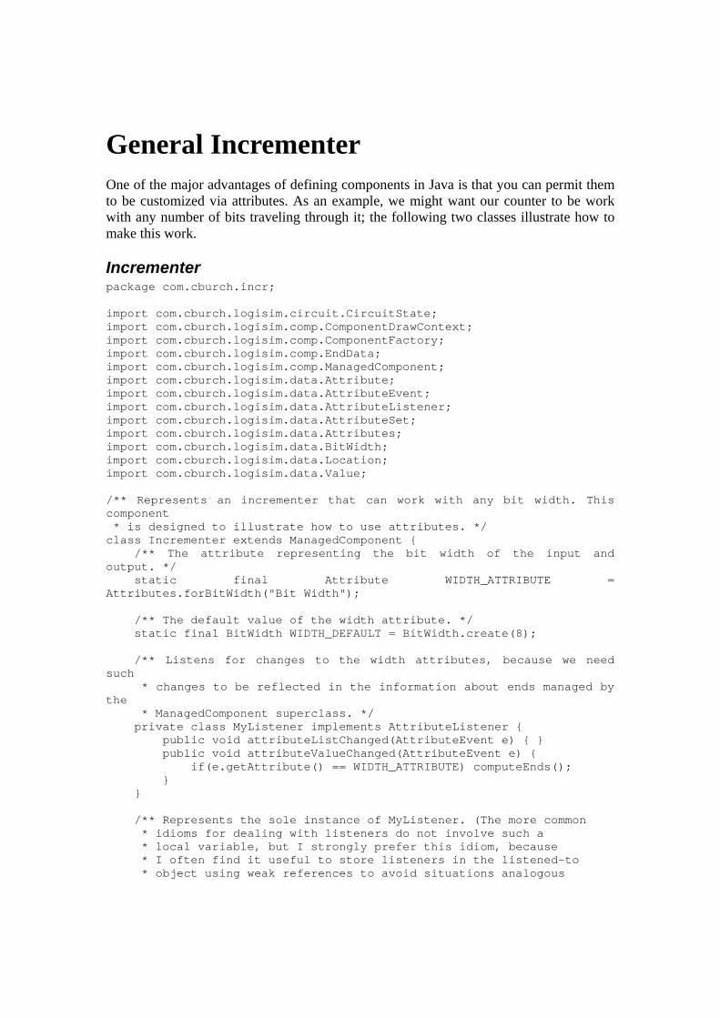
General Incrementer One of the major advantages of defining components in Java is that you can permit them to be customized via attributes. As an example, we might want our counter to be work with any number of bits traveling through it; the following two classes illustrate how to make this work.
Incrementer package com.cburch.incr; import com.cburch.logisim.circuit.CircuitState; import com.cburch.logisim.comp.ComponentDrawContext; import com.cburch.logisim.comp.ComponentFactory; import com.cburch.logisim.comp.EndData; import com.cburch.logisim.comp.ManagedComponent; import com.cburch.logisim.data.Attribute; import com.cburch.logisim.data.AttributeEvent; import com.cburch.logisim.data.AttributeListener; import com.cburch.logisim.data.AttributeSet; import com.cburch.logisim.data.Attributes; import com.cburch.logisim.data.BitWidth; import com.cburch.logisim.data.Location; import com.cburch.logisim.data.Value; /** Represents an incrementer that can work with any bit width. This component * is designed to illustrate how to use attributes. */ class Incrementer extends ManagedComponent { /** The attribute representing the bit width of the input and output. */ static final Attribute WIDTH_ATTRIBUTE = Attributes.forBitWidth("Bit Width"); /** The default value of the width attribute. */ static final BitWidth WIDTH_DEFAULT = BitWidth.create(8); /** Listens for changes to the width attributes, because we need such * changes to be reflected in the information about ends managed by the * ManagedComponent superclass. */ private class MyListener implements AttributeListener { public void attributeListChanged(AttributeEvent e) { } public void attributeValueChanged(AttributeEvent e) { if(e.getAttribute() == WIDTH_ATTRIBUTE) computeEnds(); } } /** Represents the sole instance of MyListener. (The more common * idioms for dealing with listeners do not involve such a * local variable, but I strongly prefer this idiom, because * I often find it useful to store listeners in the listened-to * object using weak references to avoid situations analogous

* to memory leaks when the listened-to object persists beyond * the intended life of the listening object. A side effect of * this is that the listener would die immediately if the listening * object doesn't maintain its own strong reference; hence the * instance variable. [It happens that the AttributeSet used here * uses strong references, but that's no guarantee that a future * version will not.]) */ private MyListener myListener = new MyListener(); /** Constructs an incrementer at the given location with the given * attributes. */ Incrementer(Location loc, AttributeSet attrs) { super(loc, attrs, 2); attrs.addAttributeListener(myListener); computeEnds(); } /** Sets up the ends of this component. */ private void computeEnds() { // Retrieve information needed for setting the ends - notice the // access to the attribute set to retrieve the width. Location loc = getLocation(); BitWidth width = (BitWidth) getAttributeSet().getValue(WIDTH_ATTRIBUTE); // Now set up the ends. setEnd(0, loc.translate(-30, 0), width, EndData.INPUT_ONLY); setEnd(1, loc, width, EndData.OUTPUT_ONLY); } public ComponentFactory getFactory() { return IncrementerFactory.instance; } public void propagate(CircuitState circuitState) { Value in = circuitState.getValue(getEndLocation(0)); Value out; if(in.isFullyDefined()) { out = Value.createKnown(in.getBitWidth(), in.toIntValue() + 1); } else if(in.isErrorValue()) { out = Value.createError(in.getBitWidth()); } else { out = Value.createUnknown(in.getBitWidth()); } circuitState.setValue(getEndLocation(1), out, this, in.getBitWidth().getWidth() + 1); } public void draw(ComponentDrawContext context) { context.drawRectangle(this, "+1"); context.drawPins(this); } }

IncrementerFactory package com.cburch.incr; import com.cburch.logisim.comp.AbstractComponentFactory; import com.cburch.logisim.comp.Component; import com.cburch.logisim.data.AttributeSet; import com.cburch.logisim.data.AttributeSets; import com.cburch.logisim.data.Bounds; import com.cburch.logisim.data.Location; /** Manufactures Incrementer components. */ class IncrementerFactory extends AbstractComponentFactory { static final IncrementerFactory instance = new IncrementerFactory(); private IncrementerFactory() { } public String getName() { return "Incrementer"; } public String getDisplayName() { return "Incrementer (General)"; } /** Creates an attribute set holding all the initial default values. This * is the only change from the ByteIncrementerClass class, where * we simply kept the definition implemented in the parent class. Here, though, * we want to insert the attribute. */ public AttributeSet createAttributeSet() { return AttributeSets.fixedSet(Incrementer.WIDTH_ATTRIBUTE, Incrementer.WIDTH_DEFAULT); } public Component createComponent(Location loc, AttributeSet attrs) { return new Incrementer(loc, attrs); } public Bounds getOffsetBounds(AttributeSet attrs) { return Bounds.create(-30, -15, 30, 30); } }
Next: Simple Counter.
Simple Counter Often we want components that aren't exclusively combinational in nature - that is, we want the component to have some memory. There is an important subtlety in defining

such components: You can't have the component itself store the state, because an individual component can appear many times in the same circuit. It can't appear directly within a circuit multiple times, but it can appear multiple times if it appears in a subcircuit that is used several times.
The solution is to create a new class for representing the object's current state, and to associate instances of this with the component through the parent circuit's state. In this example, which implements an edge-triggered 8-bit counter, we define a CounterState class to accomplish this, in addition to the Component and ComponentFactory implementations that the previous examples have illustrated. The CounterState object remembers both the counter's current value, as well as the last clock input seen (to detect rising edges).
SimpleCounter package com.cburch.incr; import com.cburch.logisim.circuit.CircuitState; import com.cburch.logisim.comp.ComponentDrawContext; import com.cburch.logisim.comp.ComponentFactory; import com.cburch.logisim.comp.EndData; import com.cburch.logisim.comp.ManagedComponent; import com.cburch.logisim.data.AttributeSet; import com.cburch.logisim.data.BitWidth; import com.cburch.logisim.data.Bounds; import com.cburch.logisim.data.Direction; import com.cburch.logisim.data.Location; import com.cburch.logisim.data.Value; import com.cburch.logisim.util.GraphicsUtil; import com.cburch.logisim.util.StringUtil; /** Represents a simple 8-bit counter. This example illustrates how a * component can maintain its own internal state. */ class SimpleCounter extends ManagedComponent { /** The width of input and output. */ private static final BitWidth BIT_WIDTH = BitWidth.create(8); // Note what's not here: We don't have any instance variables referring // to the counter's state. Using instance variables to refer to state // would be a major bug, because this component may appear in a circuit // that is used several times as a subcircuit to another circuit. Thus, // this single component would actually appear many times in the overall // circuit. Any instance variables storing state would lead to weird // interactions among the states. Instead, we need to store all state // information in an object stashed into a CircuitState. SimpleCounter(Location loc, AttributeSet attrs) {

super(loc, attrs, 2); setEnd(0, loc.translate(-30, 0), BitWidth.ONE, EndData.INPUT_ONLY); setEnd(1, loc, BIT_WIDTH, EndData.OUTPUT_ONLY); } public ComponentFactory getFactory() { return SimpleCounterFactory.instance; } public void propagate(CircuitState circuitState) { // Here I retrieve the state associated with this component via // a helper method. In this case, the state is in a CounterState // object. CounterState state = getCounterState(circuitState); Value clk = circuitState.getValue(getEndLocation(0)); if(state.getLastClock() == null || (state.getLastClock() == Value.FALSE && clk == Value.TRUE)) { // Either the state was just created, or else we're on a rising edge // for the clock input; in either case, increment the counter. Value newValue = Value.createKnown(BIT_WIDTH, state.getValue().toIntValue() + 1); circuitState.setValue(getEndLocation(1), newValue, this, 9); state.setValue(newValue); } state.setLastClock(clk); // (You might be tempted to determine the counter's current value // via circuitState.getValue(getEndLocation(1)). This is erroneous, // though, because another component may be pushing a value onto // the same wire, which could lead to conflicts that don't really // represent the value the counter is emitting.) } public void draw(ComponentDrawContext context) { context.drawRectangle(this); context.drawClock(this, 0, Direction.EAST); context.drawPin(this, 1); // I'd like to display the current counter value centered within the // rectangle. However, if the context says not to show state (as // when generating printer output), then I shouldn't do this. if(context.getShowState()) {
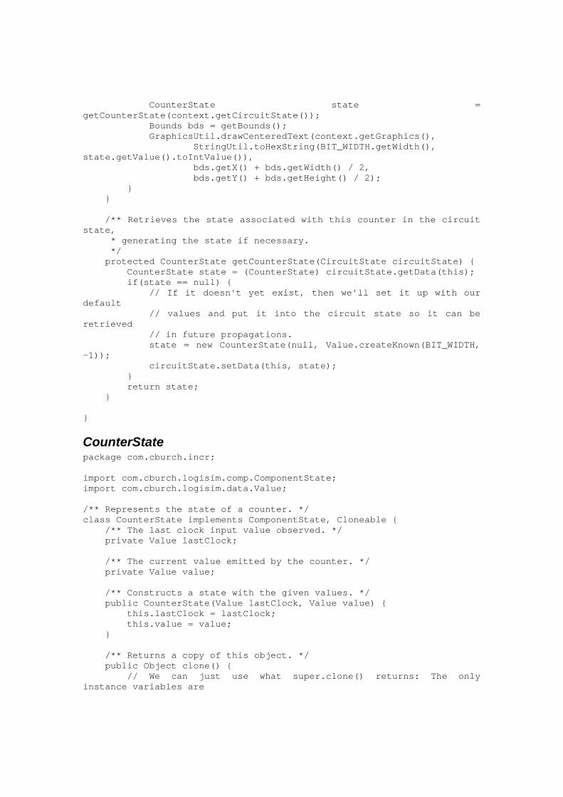
CounterState state = getCounterState(context.getCircuitState()); Bounds bds = getBounds(); GraphicsUtil.drawCenteredText(context.getGraphics(), StringUtil.toHexString(BIT_WIDTH.getWidth(), state.getValue().toIntValue()), bds.getX() + bds.getWidth() / 2, bds.getY() + bds.getHeight() / 2); } } /** Retrieves the state associated with this counter in the circuit state, * generating the state if necessary. */ protected CounterState getCounterState(CircuitState circuitState) { CounterState state = (CounterState) circuitState.getData(this); if(state == null) { // If it doesn't yet exist, then we'll set it up with our default // values and put it into the circuit state so it can be retrieved // in future propagations. state = new CounterState(null, Value.createKnown(BIT_WIDTH, -1)); circuitState.setData(this, state); } return state; } }
CounterState package com.cburch.incr; import com.cburch.logisim.comp.ComponentState; import com.cburch.logisim.data.Value; /** Represents the state of a counter. */ class CounterState implements ComponentState, Cloneable { /** The last clock input value observed. */ private Value lastClock; /** The current value emitted by the counter. */ private Value value; /** Constructs a state with the given values. */ public CounterState(Value lastClock, Value value) { this.lastClock = lastClock; this.value = value; } /** Returns a copy of this object. */ public Object clone() { // We can just use what super.clone() returns: The only instance variables are

// Value objects, which are immutable, so we don't care that both the copy // and the copied refer to the same Value objects. If we had mutable instance // variables, then of course we would need to clone them. try { return super.clone(); } catch(CloneNotSupportedException e) { return null; } } /** Returns the last clock observed. */ public Value getLastClock() { return lastClock; } /** Updates the last clock observed. */ public void setLastClock(Value value) { lastClock = value; } /** Returns the current value emitted by the counter. */ public Value getValue() { return value; } /** Updates the current value emitted by the counter. */ public void setValue(Value value) { this.value = value; } }
SimpleCounterFactory package com.cburch.incr; import com.cburch.logisim.comp.AbstractComponentFactory; import com.cburch.logisim.comp.Component; import com.cburch.logisim.data.AttributeSet; import com.cburch.logisim.data.Bounds; import com.cburch.logisim.data.Location; /** Manufactures simple 8-bit counters. This example illustrates how a * component can maintain its own internal state. All of the code relevant * to state, though, appears in the SimpleCounter and * CounterState classes. */ class SimpleCounterFactory extends AbstractComponentFactory { static final SimpleCounterFactory instance = new SimpleCounterFactory(); private SimpleCounterFactory() { } public String getName() { return "Simple Counter"; } public String getDisplayName() { return "Counter (Simple)";

} public Component createComponent(Location loc, AttributeSet attrs) { return new SimpleCounter(loc, attrs); } public Bounds getOffsetBounds(AttributeSet arg0) { return Bounds.create(-30, -15, 30, 30); } }
Next: Counter.
Counter This orientation to the Logisim libraries concludes with a fairly sophisticated counter that allows the user to alter its current value using the Poke Tool. This involves providing an implementation of Component's getFeature method so that it can return a Pokable implementation; the Pokable implementation provides access to a Caret implementation which can handle mouse and key events appropriately.
This example also illustrates what I consider a better way of structuring a library of components: Having a single class for each component, with the factory class nested privately, along with any supporting classes.
Counter package com.cburch.incr; import java.awt.Color; import java.awt.Graphics; import java.awt.event.KeyEvent; import com.cburch.logisim.circuit.CircuitState; import com.cburch.logisim.comp.AbstractComponentFactory; import com.cburch.logisim.comp.Component; import com.cburch.logisim.comp.ComponentFactory; import com.cburch.logisim.comp.ComponentUserEvent; import com.cburch.logisim.comp.EndData; import com.cburch.logisim.data.Attribute; import com.cburch.logisim.data.AttributeEvent; import com.cburch.logisim.data.AttributeListener; import com.cburch.logisim.data.AttributeSet; import com.cburch.logisim.data.AttributeSets; import com.cburch.logisim.data.Attributes; import com.cburch.logisim.data.BitWidth; import com.cburch.logisim.data.Bounds; import com.cburch.logisim.data.Location; import com.cburch.logisim.data.Value; import com.cburch.logisim.tools.AbstractCaret;

import com.cburch.logisim.tools.Caret; import com.cburch.logisim.tools.Pokable; /** Implements a counter for an arbitrary number of bits, whose value can be * modified interactively by the user. The primary purpose of this example is * to illustrate the addition of user interaction; the entry point for this * interaction is via the getFeature method. */ class Counter extends SimpleCounter { // Note that I've extended SimpleCounter to inherit all of its logic // for propagation and drawing. // The previous examples have included two separate classes for each // component. In practice, though, I personally prefer having just // one file per component type. The most convenient technique for this // is to make a private nested class for the factory, and to include // a constant referring to the factory. public static final ComponentFactory factory = new Factory(); // I'll restrict the maximum width to 12, since the rectangle drawn doesn't // have room to display more than 12 bits. static final Attribute WIDTH_ATTRIBUTE = Attributes.forBitWidth("Bit Width", 1, 12); static final BitWidth WIDTH_DEFAULT = BitWidth.create(8); private static class Factory extends AbstractComponentFactory { private Factory() { } public String getName() { return "Counter"; } public String getDisplayName() { return "Counter"; } public Component createComponent(Location loc, AttributeSet attrs) { return new Counter(loc, attrs); } public Bounds getOffsetBounds(AttributeSet arg0) { return Bounds.create(-30, -15, 30, 30); } public AttributeSet createAttributeSet() { return AttributeSets.fixedSet(Counter.WIDTH_ATTRIBUTE, Counter.WIDTH_DEFAULT); }

} /** In addition to listening for changes to the width attribute (as with * the Incrementer example), this also serves for manufacturing * the "caret" for interacting with the user. */ private class MyListener implements AttributeListener, Pokable { public void attributeListChanged(AttributeEvent e) { } public void attributeValueChanged(AttributeEvent e) { if(e.getAttribute() == WIDTH_ATTRIBUTE) computeEnds(); } /** Manufactures the caret for interacting with the user. */ public Caret getPokeCaret(ComponentUserEvent event) { return new PokeCaret(event.getCircuitState()); } } /** Implements all the functionality that interacts with the user when * poking this component. */ private class PokeCaret extends AbstractCaret { /** The circuit state the user is poking with. */ CircuitState circuitState; /** The initial value. We use this in case the user cancels the editing * to return to the initial value. (Canceling an edit is not currently * supported in Logisim, but it may be in a future version.) */ Value initValue; PokeCaret(CircuitState circuitState) { this.circuitState = circuitState; CounterState initial = Counter.this.getCounterState(circuitState); initValue = initial.getValue(); setBounds(Counter.this.getBounds()); } /** Draws an indicator that the caret is being selected. Here, we'll draw * a red rectangle around the value. */ public void draw(Graphics g) { Bounds bds = Counter.this.getBounds(); BitWidth width = (BitWidth) Counter.this.getAttributeSet().getValue(WIDTH_ATTRIBUTE); int len = (width.getWidth() + 3) / 4; g.setColor(Color.RED); int wid = 7 * len + 2; // width of caret rectangle int ht = 16; // height of caret rectangle g.drawRect(bds.getX() + (bds.getWidth() - wid) / 2, bds.getY() + (bds.getHeight() - ht) / 2, wid, ht); g.setColor(Color.BLACK);

} /** Processes a key by just adding it onto the end of the current value. */ public void keyTyped(KeyEvent e) { // convert it to a hex digit; if it isn't a hex digit, abort. int val = Character.digit(e.getKeyChar(), 16); if(val < 0) return; // compute the next value. BitWidth width = (BitWidth) Counter.this.getAttributeSet().getValue(WIDTH_ATTRIBUTE); CounterState state = Counter.this.getCounterState(circuitState); Value newValue = Value.createKnown(width, (state.getValue().toIntValue() * 16 + val) & width.getMask()); // change the value immediately in the component's state, and propagate // it immediately. state.setValue(newValue); circuitState.setValue(Counter.this.getEndLocation(1), newValue, Counter.this, 1); } /** Commit the editing. Since this caret modifies the state as the user edits, * there is nothing to do here. */ public void stopEditing() { } /** Cancel the editing. */ public void cancelEditing() { Counter.this.getCounterState(circuitState).setValue(initValue); } } // The listener instance variable, the constructor, and computeEnds all // proceeds just as in the Incrementer class. private MyListener myListener = new MyListener(); private Counter(Location loc, AttributeSet attrs) { super(loc, attrs); attrs.addAttributeListener(myListener); computeEnds(); } private void computeEnds() { Location loc = getLocation(); BitWidth width = (BitWidth) getAttributeSet().getValue(WIDTH_ATTRIBUTE); setEnd(0, loc.translate(-30, 0), BitWidth.ONE, EndData.INPUT_ONLY);

setEnd(1, loc, width, EndData.OUTPUT_ONLY); } /** Retrieves a "special feature" associated with this component. Poke support * is considered a special feature. When a user clicks on the component with * the poke tool, Logisim will call this method with the key being the Pokable * class. We should return a Pokable object in response, which it can use to * access the caret for interaction. */ public Object getFeature(Object key) { if(key == Pokable.class) return myListener; return super.getFeature(key); } public ComponentFactory getFactory() { return factory; } }
Next: Guidelines.
Guidelines Learning more
Beyond the sequence of examples provided here, the Logisim source code provides copious additional examples, though they do not always illustrate the same attention to readability and good design.
For maximum portability to future versions, you should stick as much as possible to the classes in the ...comp, ...data, and ...tools packages. Of course, you may use other packages' APIs, but they are more vulnerable to changes in future versions of Logisim.
I am generally willing to answer occasional requests for help. And bug reports and suggestions for improvements, of course, are always welcome.
Distribution
You are free to distribute any JARs you develop without restriction. The GPL restrictions do apply, however, if portions of your work are derived from portions of Logisim source code (released under the GPL). Deriving from the example code in this section of the User's Guide does not incur such restrictions; these examples are released into the public domain.

If you would like to share your library with other Logisim users, I will be happy to provide a link to a hosting Web page or the JAR file itself through the Logisim Web site. If you think your library should be built into the basic Logisim release, then I welcome your suggestion, and I'll be happy to acknowledge your contribution in Logisim releases including the work.
Next: User's Guide.
About the program Logisim is open-source software. The source code is included in the src subdirectory of the distributed JAR file.
If you find Logisim useful, please let me know. Especially do this if you are an educational institution; the information will help me in gaining support for the work.
I welcome e-mails about Logisim, including bug reports, suggestions, and fixes. When you e-mail me, please remember that I have worked hard to produce Logisim without receiving any payment from you. If you want a right to complain about the software, then I would suggest shelling out the money for a competing program to Logisim. (I know of no open-source competitors that approach Logisim's feature set.) Nonetheless, I remain interested in continuing to improve Logisim, and your suggestions will be most welcome.
Copyright notice
Copyright (c) 2005, Carl Burch.
Logisim is free software; you can redistribute it and/or modify it under the terms of the GNU General Public License as published by the Free Software Foundation; either version 2 of the License, or (at your option) any later version.
Logisim is distributed in the hope that it will be useful, but WITHOUT ANY WARRANTY; without even the implied warranty of MERCHANTABILITY or FITNESS FOR A PARTICULAR PURPOSE. See the GNU General Public License for more details.
Acknowledgements
The source code to Logisim is primarily my own work; I must acknowledge my employers who fund my work as a professor, including this program: I started the program at Saint John's University (Collegeville, Minnesota, USA) in 2000-2004, and I have continued it at Hendrix College (Conway, Arkansas, USA) from 2004 to present. I am very grateful to these colleges for giving me the time and resources to work on this

project. If only all colleges and universities had their act as together and cared as much about excellent teaching as these colleges do!
Second is Pablo Leal Ramos, who developed the Spanish translation for version 2.1.0 while studying at Hendrix as a foreign exchange student from Spain.
Finally, and just as significantly, are two groups of students that worked through early versions of Logisim: the Spring 2001 CSCI 150 classes at the College of Saint Benedict and Saint John's University, which used the most rudimentary versions when Logisim was being developed; and the Spring 2005 CS61C class at the University of California, Berkeley, which beta-tested the earliest iterations of version 2.0. These students put up with many bugs, and I am very appreciative for their patience and for their suggestions!
Several pieces of Logisim come from others' packages that Logisim uses; several of these pieces are distributed as part of Logisim.
Sun's Java API (obviously) Sun's Javahelp project
Help systems JDOM, from www.jdom.org
Reading and saving XML data. MRJAdapter, from Steve Roy
Integration with the Macintosh OS X platform. launch4j, from Grzegorz Kowalt
Allows distribution of Logisim as a Windows executable. GIFEncoder, from Adam Doppelt
Saving images as GIF files. This was itself based on C code written by Sverre H. Huseby.
And finally, I want to thank all the users who have contacted me - whether with bug reports, with suggestions, or just to let me know that they're using Logisim in their classes. I have to leave these suggesters anonymous, because I don't have their permission to mention them here, but: Thank you!