The Global Magazine of Leica Geosystems · Operational since January 2013, the topograph-ic...
32
The Global Magazine of Leica Geosystems 69
Transcript of The Global Magazine of Leica Geosystems · Operational since January 2013, the topograph-ic...

The Global Magazine of Leica Geosystems
69
2 | Reporter 69
Dear Readers,
Modern life is unthinkable without the geospatial
information that our industry generates and that
helps individuals, businesses and governments make
better informed decisions. We need reliable geo-
data to support sustainable growth; and processing
and interpreting the large amounts of data gener-
ated quickly and easily is vital.
In this issue of the Reporter you will discover why
3D data is essential. In China, geodesign and land-
scape architecture is now an established university
degree; and Leica Geosystems solutions are helping
students create 3D landscape visualizations. In the
Caspian Sea, Leica Geosystems geodynamic monitor-
ing systems are being used on an offshore oil rig to
ensure its safe operation and to protect its workers
on the high seas. In Frankfurt, Germany the fascinat-
ing history of St. Leonard's church is being brought
to light. During the renovation work the original col-
umns were discovered two meters below the current
floor. Using 3D laser scanning, an accurate 3D model
of the columns was created bringing this piece of
history to life.
The articles in this edition fit very well with the theme
at this year’s Intergeo in Essen, Germany. Our stand
shows how topography, construction, infrastructure,
cadastre, monitoring and geospatial imaging are all
interlinked and how Leica Geosystems solutions and
services help to improve the world we live in.
Juergen Dold
CEO Leica Geosystems
Editorial
Imprint
Reporter: Leica Geosystems customer magazine
Published by: Leica Geosystems AG, CH-9435 Heerbrugg
Editorial office: Leica Geosystems AG, 9435 Heerbrugg, Switzerland, Phone +41 71 727 34 08, [email protected]
Contents responsible: Agnes Zeiner (Director Communications)
Editors: Konrad Saal, Agnes Zeiner
Publication details: The Reporter is published in English,German, French, Spanish, and Russian, twice a year.
Reprints and translations, including excerpts, are subject tothe editor’s prior permission in writing.
© Leica Geosystems AG, Heerbrugg (Switzerland), September 2013. Printed in Switzerland
Cover: © Evgeniy Bogdanets
CO
NTEN
TS Monitoring Mother
Nature’s Forces
Bringing History to Life
Safety on the High Seas
From GeoDesign toLandscape Design
GNSS Live Trackingfor Cycling Fans
Preserving an African Legacy
Superstorm Sandy Recovery
Manual WorkMeans Top Quality
A New Constellation for Gold
Picture Contest:– when it has to be right
03
06
09
12
14
18
20
24
27
30

© D
uil
io G
uiz
zett
i
>>
The Global Magazine of Leica Geosystems | 3
by Elena Piantelli
The Messina region is considered one of Sicily’s
areas most vulnerable to natural disasters. As
such, the communities in this northeast region
have become all too familiar with “renewal” –
the recovery after violent earthquakes, flood-
ing, mudslides and landslides. Indeed, the
community of San Fratello, a small village 90
kilometers (56 miles) west of Messina, is still
trying to regain its footing three years after a
disastrous landslide forced almost half the pop-
ulation of 4,500 residents from their homes.
The implementation, however, of an advanced
surface monitoring system is providing authori-
ties with the ground intelligence they need to
not only help avoid the disastrous element of
surprise, it may help to stem the slide as well.
According to ISPRA (Italy’s Institute for Environmen-
tal Protection and Research), a significant contribut-
ing factor to the landslide was rainfall. About 105
mm of rain fell over the area in the eight days prior to
the destruction, overwhelming the existing drainage
system and putting the hillside village at serious risk.
On 13 February 2010, a landslide was triggered in
Riana, a district in San Fratello. The two-kilometer-
Monitoring Mother Nature’s Forces
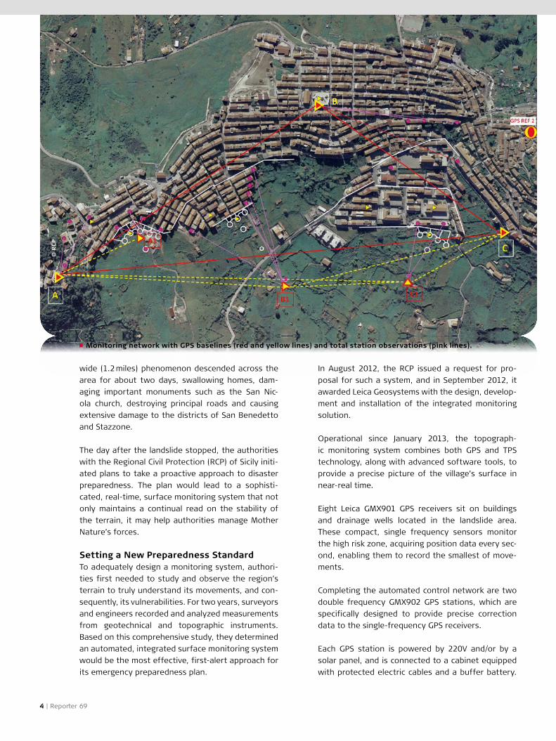
Monitoring network with GPS baselines (red and yellow lines) and total station observations (pink lines).
© R
CP
4 | Reporter 69
wide (1.2 miles) phenomenon descended across the
area for about two days, swallowing homes, dam-
aging important monuments such as the San Nic-
ola church, destroying principal roads and causing
extensive damage to the districts of San Benedetto
and Stazzone.
The day after the landslide stopped, the authorities
with the Regional Civil Protection (RCP) of Sicily initi-
ated plans to take a proactive approach to disaster
preparedness. The plan would lead to a sophisti-
cated, real-time, surface monitoring system that not
only maintains a continual read on the stability of
the terrain, it may help authorities manage Mother
Nature’s forces.
Setting a New Preparedness Standard To adequately design a monitoring system, authori-
ties first needed to study and observe the region’s
terrain to truly understand its movements, and con-
sequently, its vulnerabilities. For two years, surveyors
and engineers recorded and analyzed measurements
from geotechnical and topographic instruments.
Based on this comprehensive study, they determined
an automated, integrated surface monitoring system
would be the most effective, first-alert approach for
its emergency preparedness plan.
In August 2012, the RCP issued a request for pro-
posal for such a system, and in September 2012, it
awarded Leica Geosystems with the design, develop-
ment and installation of the integrated monitoring
solution.
Operational since January 2013, the topograph-
ic monitoring system combines both GPS and TPS
technology, along with advanced software tools, to
provide a precise picture of the village’s surface in
near-real time.
Eight Leica GMX901 GPS receivers sit on buildings
and drainage wells located in the landslide area.
These compact, single frequency sensors monitor
the high risk zone, acquiring position data every sec-
ond, enabling them to record the smallest of move-
ments.
Completing the automated control network are two
double frequency GMX902 GPS stations, which are
specifically designed to provide precise correction
data to the single-frequency GPS receivers.
Each GPS station is powered by 220V and/or by a
solar panel, and is connected to a cabinet equipped
with protected electric cables and a buffer battery.

GPS Monitoring Station
© D
uil
io G
uiz
zett
i
The Global Magazine of Leica Geosystems | 5
structure, such as installing new drainage wells and
constructing other support structures, mitigating the
town’s risk of severe damage from future natural
disasters.
It is likely that landslides will descend on San Fratello
again, but by flooding the area with their own net-
work of technology, authorities may now have the
means to turn the event into an exercise in “pre-
paredness” rather than “disaster.” And that may give
comfort to both the residents and the authorities
charged with trying to protect them.
About the author:
Elena Piantelli has a degree in natural science and
works in Business Development for Monitoring Solu-
tions at Leica Geosystems S.p.A. based in Cornegliano
Laudense/Italy.
The communication among the stations and the mas-
ter unit station, which houses the management soft-
ware, is guaranteed by a wireless LAN 5 GHz device.
The continuous GPS readings are collected by the
Leica GNSS Spider software, which is installed on
a dedicated PC on site. The software manages the
individual GPS sensors, automatically calculates the
baseline and sends the information to the RCP.
The Deformation Data StreamThe automated management of the GPS receivers
and the data analysis tools are maintained by the
RCP’s control center, which is based in the city of
Palermo, about 140 km (87 mi) from San Fratello. The
centralized control center has a network of com-
puters to receive the GPS and other supplemental
data, and it has specialized data analysis software
to enable the RCP to study the data provided by the
different instruments.
Although the frequency of the baseline calculation
depends on the RCP’s specific needs, at present, the
automated monitoring system provides measure-
ment data every hour. RCP personnel can access the
system at any time to consult the measurements and
modify acquisition parameters, thanks to the remote
control features of the solution and an opportune
remote control software.
In addition to the automated GPS monitoring system,
50 prisms are permanently set on buildings for rou-
tine measurement by a Leica TS30 automatic total
station. Using a network of six measurement pillars,
a surveyor positions the total station to perform an
automatic measuring cycle, surveying each prism
point, and enabling users to produce a topographic
analysis of the measurement data.
Measurements and surveys are made on a monthly
basis but the frequency can change according to
specific requests based on the stability of the area
or changing environmental and climatic conditions,
which are considered hazardous.
Strategies to Stabilize SubsidenceAll of the information gathered by the system is
promptly delivered to the Office for Civil Protection
so the data can be validated and integrated into
the emergency plan. By having accurate, near-real
time data, authorities have been able to identify and
implement strategies to improve San Fratello’s infra-

6 | Reporter 69
Bringing History to Life
by Theo Drechsel
The recent restoration of St. Leonhard's Church
in Frankfurt, Germany drew much attention
around the world. Not only in the form of many
publications on the subject, but also by the con-
stant flow of fascinated visitors from around
the world who come to tour the church. The
excavations, which uncovered 70 skeletons and
a variety of burial objects, were documented
not least thanks to the critical role played by 3D
laser scanners from Leica Geosystems. The data
was even used to create a 3D model of the sup-
port structure on a scale of 1:20.
From 2004 through 2008 the external facade, roofs
and tower dormers were restored. Interior restora-
tion of the church finally began in 2011. The goal of
Frankfurt’s municipality was to revert St. Leonhard's
Church back to the late Gothic style due to the vari-
ety of different architectural styles used on the inte-
rior. The floor was also to be lowered, as the interior
was raised repeatedly over the centuries to protect
against flooding by the Main River.
An assessment of the current condition had to be
made before the restoration, so in 2009 Frankfurt's
Central Building Department commissioned local
engineering firm Steuernagel Ingenieure GmbH for
the job. “After testing, we realized right away that 3D
laser scanning would be the only option for measure-
ment due to the particularly complex nature of the
building,” recalls Managing Director Kai Steuernagel.
“This is why we used the HDS6200 laser scanner
and a ScanStation C10 from Leica Geosystems, which
guarantee the required accuracy of ± 10 mm (0.4 in).”
The goal of the project was to document the inter-
mediate results of construction as the restoration
progressed. In 15 days the surveyors fully scanned
each phase of the excavation down to a depth of
almost 3.5 meters (11 ft). The entire interior of the
church, including all auxiliary rooms, the ceiling arch-
es and both apses (towers) were captured in exact
detail. Great value was placed on the selection of
the laser scanning positions to minimize shadowing
during the scanning process. “We scanned one sup-
port structure from 16 different positions,” reported
Christof Kremer. “Our knowledge and experience as

Accurate 3D model of the support structure on a
scale of 1:20 based on the 3D laser scan
The Global Magazine of Leica Geosystems | 7
>>
surveyors ensured the high precision and quality of
the scans.”
The big challenge for the expert surveyors was the
accurate and thorough representation of the Gothic
architectural style with its frescoes and many details,
particularly with the intention of creating the floor
plan as a dimensional site plan. This was prepared in
detail, down to the benches and floor coverings; by
the end of the project roughly 17 billion points had
been scanned.
The software 3D Reshaper from Technodigit, a Leica
Geosystems sister company, proved itself brilliant-
ly during this project. It was used for modeling by
Steuernagel and offered the surveying experts many
options. In conjunction with the 3D laser scanner
from Leica Geosystems, it offers considerable add-
ed value thanks to its visualization options, which
also enthralled the Central Building Department.
The most impressive element, though, was the laser
scanner itself, which exhibited its strengths particu-
larly in close range applications thanks to its high
precision and resolution.
The advantages of laser scanning were highly evi-
dent in other areas as well. When the Central Building
Department asked Steuernagel for an additional rep-
resentation after the work was completed, it could
be created and submitted quickly without having to

© m
ne
um
an
n_1
00
- F
oto
lia.c
om
St. Leonhard's Church isn't just one of the sights to
see in Frankfurt. It is the most valuable church in
the Hessian metropolis. Located on the north bank
of the Main River in the old town it was erected
in 1219 as a late Romanesque basilica and subse-
quently remodeled in the neo-Gothic style. The first
ever Frankfurt book fair was held in the north nave
of the church in 1450. A hanging arch is found in the
integrated chapel of St. Salvator built from 1500 to
1515. Arches of this type consist of stone arch ribs
and are rare in Europe due to their complex design.
During the Second World War, St. Leonhard's Church
was the only one in Frankfurt to miraculously remain
almost entirely intact.
St. Leonhard's Church
8 | Reporter 69
return to the site to carry out more work. The archi-
tect, who is located in Fulda, about 100 km (62 mi)
away from the church, is also delighted. He used
to have to visit the property frequently to clear up
outstanding issues, but now he gets the informa-
tion he needs with much less effort thanks to the
Leica TruView freeware. With this software, he can
view extensive point clouds directly in a web browser
without the need for CAD experience.
The icing on the cake of a very successful project was
the “tangible” 3D model, accurate down to the mil-
limeter (including every joint), created by Steuernagel
and a partner at the end of the project. A 3D printer
was used to construct a complete support structure
around the excavation area in a scale of 1:20. The
three-dimensional workpiece was constructed by
computer control using the specified dimensions and
shapes from the CAD model.
“If nothing else, this museum-quality 3D presenta-
tion model confirms my opinion that laser scanning is
currently unbeatable where 3D data and 3D models
are needed,” stressed Kai Steuernagel.
About the author:
Theo Drechsel is the owner of the specialist metrol-
ogy and quality assurance PR agency 4marcom + PR!
based in Unterschleissheim near Munich.
Founded in 1992, the Steuernagel Ingenieure GmbH
engineering firm is located in Frankfurt am Main and
focuses on surveying, civil engineering and graphical
data processing. Since the beginning, Steuernagel has
used only Leica Geosystems measurement systems.
Regarding its latest purchase, two Leica HDS7000
Steuernagel Ingenieure GmbH
laser scanners, Managing Director Kai Steuernagel
had this to say: “We invested in the laser scanners
because we want to build a mainstay for the future,
expanding our portfolio as a large engineering firm
in Frankfurt.”

© E
vge
niy
Bo
gd
an
ets
>>
The Global Magazine of Leica Geosystems | 9
Safety on the High Seasby Evgeniy Bogdanets and Anton Ivanov
Government awareness of the need for
increased safety on offshore works is increas-
ing worldwide. Russia has a strong interest in
offshore safety and is in the process of prepar-
ing a bill concerning “protecting the seas of the
Russian Federation against oil pollution”. There
are currently two oil-drilling rigs in operation,
both belonging to “Lukoil” Ltd. The bill is not yet
ready or obligatory, but Lukoil’s directors have
already initiated geodynamic monitoring sys-
tems on a maritime, ice-resistant platform over
the Yuri Korchagin oil deposit to ensure safe
operation and to protect workers from unex-
pected occurrences on the high seas.
The Yuri Korchagin oil deposit was discovered in
2000 and is located 180 km (110 mi) from Astrakhan
in the northern part of the Caspian sea, at an aver-
age sea depth of 11 – 13 m (36 – 43 ft). The rig began
working in spring 2010 and consists of two blocks:
the production and the accommodation facility.
Preliminary Evaluation The owner and operator “Lukoil-Nizhnevolzhskneft”
Ltd. put on a competition for the monitoring project,
which was won by the Perm State Technical Universi-

© E
vge
niy
Bo
gd
an
ets
Leica AR25 Reference Station
10 | Reporter 69
infrastructure. Natural seismic activity in the region
can aggravate the risk of man-made seismic events,
which is further proof that geodynamic monitoring of
facilities is essential.
Mathematical deformation modeling of the rock
mass and the earth surface during oil production at
the Yuri Korchagin field performed by experts from
the Perm State Technical University have shown that
maximum seabed subsidence is 100 mm (4 in). Pre-
liminary evaluation of the general rock stress level
during commingled oil and gas production indicates
that maximum pay zone compaction reaches 890 mm
(35 in). This means the development of gas reserves
at the field is the main driving force behind seabed
subsidence.
The Right Monitoring Approach The PSTU scientists proposed a two-segment moni-
toring system: the first segment is an automated
monitoring system using Leica GNSS Spider software
and the second is control monitoring performed
upon control reference points onshore. Both seg-
ments involve sea and onshore works.
The shore reference network uses a reference sta-
tion installed on the roof of a Lukoil-Nizhnevolzhs-
kneft Ltd. office and connected to a server running
Leica GNSS Spider, which is regularly checked by the
chief surveyor. In addition, raw measurements of the
four constantly operating sensors are saved on this
computer. The sea segment of the monitoring sys-
tem consists of three sets of GNSS equipment with
antennas set up permanently on the three edges of
the rig’s main deck.
A geodynamic polygon of ten control sites has been
created for the shore segment monitoring. Baseline
solutions to the rig are computed from a single mas-
ter site. All other sites are used to control the stabil-
ity of the master site. If the master is moved or lost
for any reason, its role transfers to another site.
The combination of sea and onshore segments
results in a collection of raw measurements of all
GNSS sensors combined on the computer of Lukoil-
Nizhnevolzhskneft’s chief surveyor. Leica GNSS Spi-
der allows gathering and archiving data automati-
cally. The system is configured to compute sensor
coordinates (points on the edges of the main deck)
in real-time every second, as well as with hourly and
twelve hour intervals in post-processing. The results
ty (PSTU). The Mining GIS and Surveying department
of PSTU had already had successes with projects in
the area of deposit extraction and considered pro-
fessional, quality equipment and software a crucial
part of successful project completion. The scientists
chose Leica Geosystems GNSS equipment to moni-
tor the vertical and horizontal displacements of the
oil rig.
The Caspian rig is permanently fixed to the seabed
on six carriers. During the extraction process, the de-
oiled rock is repacked so the terrain generally settles
down. However, if irregularities occur in the process,
the rig might lurch. Therefore platform position mon-
itoring is crucial to prevent dangers.
If subsidence processes develop gradually, produc-
tion-related subsidence should not impact the facili-
ties. However, local irregular seabed displacements
can occur, which may pose a threat to the oilfield

© E
vge
niy
Bo
gd
an
ets
A Leica AR10 antenna monitors movements of the oil rig.
The Global Magazine of Leica Geosystems | 11
Comparing the control monitoring results with a drill-
ing map leads PSTU to believe that smaller move-
ments of 20 mm (0.8 in) are mainly caused by engine
lowering and lifting. The Leica Geosystems monitor-
ing installation remains essential to keeping all rel-
evant parties informed.
About the authors:
Evgeniy Bogdanets is Mining GIS and Surveying chair
assistant at PSTU. [email protected]
Anton Ivanov is Public Relations Manager at Navgeo-
com, Leica Geosystems' Master Distributor in Russia.
of coordinate calculations are presented in a move-
ment diagram and are used to make a conclusion
about sensor stability – and therefore rig stability.
Section two of the system is controlling the monitor-
ing results by making long-term GNSS observations
on permanent onshore base stations. To ensure the
stability of the control network, first-order leveling
was performed before starting GNSS observations.
A Stable Oil Platform Since the installation of the monitoring system, the
results show that control measurements and auto-
mated monitoring data correlate: the nature of sub-
sidence and rises is completely identical, concluding
that the real-time monitoring gives correct results.
The sensor displacements are of non-permanent
nature; their values are small and for the most part
do not exceed measurement accuracy, which indi-
cates that their location is permanent and stable.

12 | Reporter 69
From GeoDesign to Landscape Design
Landscape Architects are not surveying profes-
sionals, but understanding how to apply differ-
ent surveying methods, as well as the workflow
and effort necessary to create the data they
use for their design concepts, is essential. In
June 2013, the Leica Geosystems team in Nan-
jing, China provided instruments, know-how and
manpower for the workshop “From GeoDesign
to Landscape Design”, taught by Prof. Dr. Li Pang
and Prof. Peter Petschek, to educate future
Landscape Architects on different surveying
methods.
by Dr. Li Pang and Prof. Peter Petschek
In the past years, the role of Landscape Architec-
ture in China has completely changed. The Chinese
government now considers it equal in importance
to Architecture and Planning. This is also reflected
in the university system. Landscape Architecture is
an established university degree equal to other dis-
ciplines in the planning and construction area. At
South East University (SEU) in Nanjing, one of the
top universities in this field, the subject is taught at
Bachelor, Master and PhD levels.
GNSS and laser scanning are new buzzwords in Land-
scape Architecture. But which surveying technolo-
gy is best suited for which project, how much time
does it take, what are the measurement principles
of these instruments and how do you collect land-
scape information and build landscape models? The
instructors of the “From GeoDesign to Landscape
Design” workshop teamed up with Leica Geosystems
to teach students at SEU how to solve these and
other surveying related questions.
During the first part of the workshop, the students
learned to use the Leica Geosystems laser scanning
technology on site in an area covered with abundant
trees and bushes and with a pond in the middle. The
advantages of measuring millions of points within a
very short time quickly became clear. But the stu-
dents also realized that laser scanning is not the
answer to every task in landscape architecture - for
even more precise landscape design/planning and
stake-out in the field the students were introduced
to the Leica Builder total station.
In the second part of the workshop the students
were taught how to create Digital Terrain Models

making the development of landscape design solu-
tions in China easier.
About the authors:
Li Pang received her PhD at ETH Zürich and teaches
Landscape Architecture at SEU.
Peter Petschek is a graduate landscape architect and
professor at HSR University of Applied Sciences Rap-
perswil/Switzerland.
The Global Magazine of Leica Geosystems | 13
(DTM) from the data observed with the Leica Builder.
AutoCAD Civil 3D with its many possibilities to ana-
lyze and manipulate the terrain was used for this
purpose. The DTM know-how was then applied to a
design project. Prof. Dr. Li Pang gave the students
guidance on how to achieve a design in Landscape
Architecture based on existing topography.
By understanding the entire process involved from
survey to final data delivery Landscape Architects
can communicate more efficiently with Surveyors,
3D Survey Data for Landscape Architecture
Land Survey Data is the basis for every Landscape
Architecture project. With an increased demand for
3D landscape visualizations and the need for sci-
entific decision-making processes in contemporary
landscape architecture design/planning, precise land-
scape data is becoming ever more essential. Existing
topography, vegetation, buildings and infrastructure
have to be precisely located in digital plan format in
order to develop design concepts for urban green
spaces, plazas, parks and gardens.

14 | Reporter 69
by Thomas Aigner
The annual Bayern Rundfahrt, or Tour of Bavar-
ia, (www.bayern-rundfahrt.com) is Germany's
largest professional stage race. This year the
Regional Surveying and Geoinformation Office
supported the event with maps, aerial photos,
3D animations and live tracking. With live track-
ing, GNSS receivers mounted on escort vehicles
transmit the co-ordinates of the cyclists at the
front and rear of the pack to a centralized ser-
vice. The positions are displayed on a special-
ly adapted Bavarian Surveying Administration
BayernAtlas for cycling fans to track the race
conveniently in real time over the Internet.
In 2012, the Bavarian Broadcasting Company's “BR-
Radltour” was the first public cycling event the
Bavarian Surveying Administration supported with
live tracking. To meet the increased needs of the
second live tracking event – the Tour of Bavaria in
May 2013 over a distance of 783.5 km (487 mi) – the
Bavarian Surveying Administration chose to use more
professional instruments. The previously used simple
GPS tracking transmitters had difficulties with posi-
tion accuracy and mobile reception.
Across Bavaria, powerful Leica Geosystems GNSS
sensors Viva GS15 and GS10 have been used at 51
Cadastral Offices for satellite-supported measur-
ing tasks in the land registry for several years now.
Thus the agency has both experience in using the
devices and sufficient instruments which could be
provided for the Tour of Bavaria. In addition to the
powerful GNSS evaluation hardware, the high-quality
mobile antenna accessory promised a more stable
connection, even in areas of the state with weak
coverage, in comparison to the simple GPS tracking
transmitters. Last, but not least, the many options
for supplying power, including internal batter-
GNSS Live Tracking for Cycling Fans

© S
CH
AA
F /
Baye
rn R
un
dfa
hrt
>>
The Global Magazine of Leica Geosystems | 15
veying Administration escort personnel were only
available part of the time for the Tour of Bavaria,
the instruments had to be operated (set-up, started,
power supply monitored) by whoever else was in the
vehicle, i.e. inexperienced users. Despite this, reliable
functioning had to be ensured.
Orgatour: Successful Equipment Test In addition to materials, training is an important part
of any cyclist's race preparation. Therefore it was
possible to put the instruments through their paces
in advance of the race. The selected equipment (a
Leica AS10 GNSS antenna with a GAT18 GMS/UMTS
antenna on the roof and a Leica Viva GS10 receiver
with power supply in the car) was tested by the event
organizer in May 2013 during a so-called Orgatour, a
preparatory exploration of the route. It became evi-
dent at this point that the right choice of equipment
had been made. The accompanying personnel were
able to reliably operate the test instrument after
ies, external batteries and supply via a 12V vehicle
electrical system, guaranteed a flexible and secure
solution.
By nature, complex, high-performance systems also
place greater demands on the user. The critical ques-
tion then arose as to whether the selected Leica
Viva GS10 receiver would be easy enough to oper-
ate during an activity as turbulent as a bicycle race.
During the 2012 BR-Radltour, only the very front and
rear positions were tracked, but for the 2013 Tour
of Bavaria, the position of the peloton (main group
of cyclists) also had to be visible as a third position,
should some cycling pros successfully manage an
exciting leap ahead of the pack.
The three escort vehicles: the police's lead vehicle,
the sport physician's vehicle and the event organiz-
er’s “sag wagon” were each equipped with a Leica
Viva GS10 receiver. Since some of the Bavarian Sur-
GSM and GNSS antenna setup
© T
ho
mas
Aig
ne
r /
LVG
16 | Reporter 69
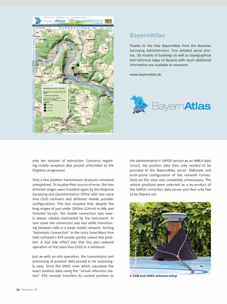
BayernAtlas
Thanks to the free BayernAtlas from the Bavarian
Surveying Administration, free detailed aerial pho-
tos, 3D models of buildings as well as topographical
and historical maps of Bavaria with much additional
information are available to everyone.
www.bayernatlas.de
only ten minutes of instruction. Concerns regard-
ing mobile reception also proved unfounded as the
Orgatour progressed.
Only a few position transmission dropouts remained
unexplained. To localize their source of error, the two
affected stages were travelled again by the Regional
Surveying and Geoinformation Office with two Leica
Viva GS10 receivers and different mobile provider
configurations. This test revealed that, despite the
long stages of just under 200 km (124 mi) in hilly and
forested terrain, the mobile connection was near-
ly always reliably maintained by the instrument. In
rare cases the connection was lost while transition-
ing between cells in a weak mobile network. Setting
“Automatic Connection” in the Leica SmartWorx Viva
field software’s RTK profile quickly solved this prob-
lem. A nice side effect was that this also reduced
operation of the Leica Viva GS10 to a minimum.
Just as with on-site operation, the transmission and
processing of position data proved to be surprising-
ly easy. Since the GNSS rover which calculates the
exact position data using the “virtual reference sta-
tion” RTK concept transfers its current position to
the administration's SAPOS service as an NMEA data
record, the position data then only needed to be
provided to the BayernAtlas server. Elaborate and
error-prone configuration of the network connec-
tions on the rover was completely unnecessary. The
vehicle positions were collected as a by-product of
the SAPOS correction data server and then only had
to be filtered out.

© T
ho
mas
Re
ine
l /
LVG
Good preparation leads to a successful race Every imaginable preparatory measure for smooth
technical support of the race had thus been taken.
The day before the first stage, the escort vehicles
were outfitted and the occupants where instructed
in the operation of the instruments. Although each
installation arrangement wasn't yet known and many
of the power sources had already been taken up by
the tour's mobile needs, the optimum solution was
quickly found for each vehicle using either batteries
or the vehicle's electrical system. Time-consuming
recharging of batteries could even be fully dispensed
with, thanks to good advance planning and compre-
hensive accessories.
Good preparation enabled trouble-free live tracking
of the Tour of Bavaria. The only thing worth com-
plaining about was the cold, wet weather during
the tour, but even this didn't negatively affect the
instruments in any way. Despite constant rain, the
equipment served flawlessly and reliably transmitted
the position data of the racing cyclists. Subsequent
evaluation of the transmitted NMEA data showed
that an impressive 75 % of all points achieved an RTK
accuracy of about 2 cm (0.8 in) and another 24 % a
DGPS accuracy of about 1.5 m (4.9 ft) – thus by far
exceeding the requirements.
Apart from the technical details, both the tour orga-
nizers and many other people interested in the
2013 Tour of Bavaria profited from the Surveying
Administration's “live-tracking project”. The feed-
back received was also correspondingly positive.
Both visitors to the Bavarian Surveying Administra-
tion's information stand at the stage destinations
and fans at home were able to track the race's prog-
ress live at all times and estimate the cyclists' arrival
at the finish line. At the end, the Tour of Bavaria
organizers expressed their sincere thanks for the
successful project. As far as the Bavarian Surveying
Administration is concerned, there is nothing stand-
ing in the way of a repeat performance at the 2014
Tour of Bavaria.
About the author:
Thomas Aigner is a Surveying Engineer (UAS) at the
Bavarian Agency for Surveying and Geographic Infor-
mation (Landesamt für Vermessung und Geoinforma-
tion / LVG) and is responsible for all Cadastral Offices
in Bavaria. [email protected]
The Global Magazine of Leica Geosystems | 17

© A
ngu
s Fo
rbe
s
18 | Reporter 69
Preserving an African Legacyby Michelle Dye
There’s a spectacular mountain range linking
South Africa and Lesotho that is known in some
quarters as the Drakensberg, ‘dragon moun-
tain’, and by Bantu-speakers as uKhahlamba,
‘the row of upward-pointing spears’. But it is the
San people who left the greatest legacy in these
mountains: a treasure trove of priceless art. The
San people lived in the uKhahlamba Drakens-
berg range for about 4000 years, during which
time they adorned more than 600 known sites
with 40,000 individual paintings, the largest and
most concentrated collection of rock art in sub-
Saharan Africa. The paintings are outstanding
in their quality. Their diversity of subject and
their exquisite depiction of animals and human
beings and their world-wide significance con-
tributed to the uKhahlamba Drakensberg Park
being listed as a UNESCO World Heritage Site
in 2000. Leica Geosystems’ cutting-edge HDS
technology is helping to preserve this legacy.
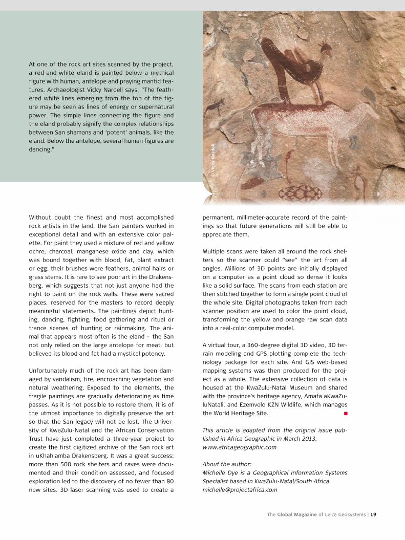
© V
ick
y N
ard
ell
permanent, millimeter-accurate record of the paint-
ings so that future generations will still be able to
appreciate them.
Multiple scans were taken all around the rock shel-
ters so the scanner could “see” the art from all
angles. Millions of 3D points are initially displayed
on a computer as a point cloud so dense it looks
like a solid surface. The scans from each station are
then stitched together to form a single point cloud of
the whole site. Digital photographs taken from each
scanner position are used to color the point cloud,
transforming the yellow and orange raw scan data
into a real-color computer model.
A virtual tour, a 360-degree digital 3D video, 3D ter-
rain modeling and GPS plotting complete the tech-
nology package for each site. And GIS web-based
mapping systems was then produced for the proj-
ect as a whole. The extensive collection of data is
housed at the KwaZulu-Natal Museum and shared
with the province’s heritage agency, Amafa aKwaZu-
luNatali, and Ezemvelo KZN Wildlife, which manages
the World Heritage Site.
This article is adapted from the original issue pub-
lished in Africa Geographic in March 2013.
www.africageographic.com
About the author:
Michelle Dye is a Geographical Information Systems
Specialist based in KwaZulu-Natal/South Africa.
The Global Magazine of Leica Geosystems | 19
Without doubt the finest and most accomplished
rock artists in the land, the San painters worked in
exceptional detail and with an extensive color pal-
ette. For paint they used a mixture of red and yellow
ochre, charcoal, manganese oxide and clay, which
was bound together with blood, fat, plant extract
or egg; their brushes were feathers, animal hairs or
grass stems. It is rare to see poor art in the Drakens-
berg, which suggests that not just anyone had the
right to paint on the rock walls. These were sacred
places, reserved for the masters to record deeply
meaningful statements. The paintings depict hunt-
ing, dancing, fighting, food gathering and ritual or
trance scenes of hunting or rainmaking. The ani-
mal that appears most often is the eland – the San
not only relied on the large antelope for meat, but
believed its blood and fat had a mystical potency.
Unfortunately much of the rock art has been dam-
aged by vandalism, fire, encroaching vegetation and
natural weathering. Exposed to the elements, the
fragile paintings are gradually deteriorating as time
passes. As it is not possible to restore them, it is of
the utmost importance to digitally preserve the art
so that the San legacy will not be lost. The Univer-
sity of KwaZulu-Natal and the African Conservation
Trust have just completed a three-year project to
create the first digitized archive of the San rock art
in uKhahlamba Drakensberg. It was a great success:
more than 500 rock shelters and caves were docu-
mented and their condition assessed, and focused
exploration led to the discovery of no fewer than 80
new sites. 3D laser scanning was used to create a
At one of the rock art sites scanned by the project,
a red-and-white eland is painted below a mythical
figure with human, antelope and praying mantid fea-
tures. Archaeologist Vicky Nardell says, “The feath-
ered white lines emerging from the top of the fig-
ure may be seen as lines of energy or supernatural
power. The simple lines connecting the figure and
the eland probably signify the complex relationships
between San shamans and ‘potent’ animals, like the
eland. Below the antelope, several human figures are
dancing.”

20 | Reporter 69
Superstorm Sandy Recoveryby Angus W. Stocking, LS
When Superstorm Sandy hit the East Coast in
October 2012, it left a wide swath of damage and
destruction in its wake. Gayron de Bruin (GdB),
a 14-person land surveying and engineering firm
based in Bethpage, N.Y., a Long Island hamlet,
was among the businesses severely affected.
The firm, which has been standardized on Lei-
ca Geosystems instruments for several years,
specializes in applying progressive technology
to traditional survey tasks. They were an ear-
ly adopter of GNSS, robotic total stations and
other progressive instrumentation, and one of
the first providers of GIS expertise and consult-
ing in the Long Island area. The combination of
modern technology, high standards and excel-
lent service allowed the firm to thrive despite
challenges.
“I was actually at work during the day as the storm
got going,” says GdB President Christine Gayron,
LS. “I went home at 4:00 pm as it got more intense.
We lost power of course – everyone did – and had

The Global Magazine of Leica Geosystems | 21
ways, and major state parks, such as Jones Beach
and Robert Moses. “Sandy washed water over the
entire island and parkway in some spots, completely
wiping out the dunes that normally protect the road,”
Gayron says. “So we didn’t know what to expect; we
weren’t even sure we’d be able to get to the site.”
Fortunately, NYSDOT had already made progress
clearing the road, using snowplows and other meth-
ods to push away sand. When GdB trucks arrived,
state troopers were onsite to restrict access but,
in the cooperative spirit that prevailed after Sandy,
waved the surveyors through to do their work.
GdB had been asked to complete an emergency con-
trol survey to support photogrammetric and aerial
LiDAR mapping being performed to assess parkway
damage. NYSDOT was concerned about the parkway
being buckled or undermined by storm surges. “NYS-
DOT set targets before the storm and didn’t know if
they would still be there,” says Gayron, “And if they
were in place, would they still be visible or would
some IT issues. A bigger problem was gas; In the days
after the storm just getting to work was hard for our
employees. Filling up trucks meant waiting in line at
the filling station for hours.”
GdB felt more pressure than most businesses to get
up and running quickly. The firm has a Term Agree-
ment for Survey Services (TASS) with the New York
State Department of Transportation (NYSDOT) and
knew that preliminary survey work would be needed
prior to important storm recovery projects. “Sandy
hit on Monday, and we didn’t have power at the
office until Thursday,” says Gayron. “I called our NYS-
DOT contact that very day, to let them know we
were available.” NYSDOT wasted no time. GdB had an
assignment the next day and early Saturday morning
two crews were on their way to Ocean Parkway, a
state road that runs along one of the barrier beach
islands on the south side of Long Island.
In fact, Ocean Parkway is the only connection
between several islands, communities, other park- >>

A GdB field crew uses a Leica Viva GS15 to survey post-Sandy beach erosion for the town of Oyster Bay.
22 | Reporter 69
they be covered with sand? We found that most
were there; many had to be swept off, and a handful
had to be reset.” The job involved “only” a hundred
points or so but, like the rest of Long Island, crews
would be dealing with Sandy’s aftermath. And GdB’s
practice of collecting GNSS data twice for each point,
at different times of day, compounded the challeng-
es. “Really,” says Gayron, “We were collecting about
200 points, in difficult conditions.”
Because of uncertainty about cell phone use and the
state of NYSNET, the NYSDOT continuously operated
reference station (CORS) system, GdB brought every
receiver in its shop out to Ocean Parkway. “We were
prepared to set up a base station, if needed,” Gay-
ron explains. “But during the project, we were able
to use a combination of cell phones and radios to
get NYSNET data, and we were able to do this work
as accurately as we could have pre-Sandy. Getting
around was hard sometimes, but getting the preci-
sion we needed wasn’t.” An added complication was
that midway through the project, the NYSNET sta-
tion coordinates were updated. But even that went
smoothly; GdB is an all Leica Geosystems office and
used Leica Geo Office to update the GNSS data from
the Leica GS15 and System 500 receivers with the
changed coordinates. Surveyors were able to make
the mid-project conversion without a hitch.
Crews worked east and west from Gilgo Beach,
near the center of the most damaged area. Work-
ing 10-hour days, the crews made good progress.
“We were able to survey 92 out of the 100 control
points we were assigned,” says Gayron. “The eight
we didn’t get to were on marsh islands that were
inaccessible due to Sandy. We also helped out NYS-
DOT by uncovering or resetting a lot of the targets
they’d been setting.”
In two long weekend shifts and some office time
on Monday, data was collected, post-processed,
checked for quality and delivered to NYSDOT less
than 72 hours after the initial call. In addition to
assessing damage and planning repairs, the data is
also being used to calculate the volume of sediment
moved by Sandy.
Several smaller, but still urgent, projects kept GdB
busy in the weeks following. For example, the village
of Saltaire’s surveyor John Mayer, LS, wanted GdB to

A Leica Viva TS15 is used to survey Udalls Pond in Nassau County to determine the sedimentation effects of Sandy.
The Global Magazine of Leica Geosystems | 23
the bridge. In some areas, GdB was forced to use
a “custom pond-crossing gadget,” which is essen-
tially a sled with a Leica Geosystems prism attached;
crews towed the sled across areas of thick mud to
capture profiles of surfaces that defied walking and
boating. Using these methods, GdB was able to show
that sediment hadn’t returned to dredged areas, and
around the bridge (desirable) sediment buildup had
actually increased. “It was nice to deliver some good
news for a change,” says Gayron.
This article is adapted from the original issue pub-
lished in POB Magazine March 2013.
About the author:
Angus W. Stocking, L.S., is a licensed land surveyor
who now writes full time on infrastructure topics.
find the village’s missing sand. Saltaire is a village on
Fire Island, another of Long Island’s barrier islands,
and it’s one of the few Long Island communities that
can only be reached by boat or on foot. Sandy wiped
out dunes that the village depends on to protect
residential areas from tides and erosion, so a beach
section survey was needed to find areas where sand
could be removed for dune reconstruction. By law,
sand can only be repositioned if it’s above a defined
elevation. Sand is so important to Saltaire that the
mayor got involved and even made a site visit. But
the mayor didn’t like what the survey said. “We had
to tell him, ‘No sand’,” says Gayron. “Sandy washed
it all away.”
Nassau County also called, worried about their mud.
“We’ve been doing pre-dredge and post-dredge sur-
veying for the county since 2008,” Gayron explains,
“monitoring sediment buildup in the pond and near
a bridge. Basically, they were wondering if four years
of work had been undone.”
The “pond” is Udall’s Pond, a 230-acre, tidally influ-
enced wetland area. It’s muddy, but most of the
hydrographic work can be done with a boat or from

24 | Reporter 69
Manual Work Means Top QualityEvery detail counts. With this in mind, Leica
Geosystems develop instruments and fastidi-
ously design complementary accessories, such
as prisms, for these instruments. Gerhard Söns-
er, product manager for original accessories,
explains the steps required to manufacture a
360° prism, such as the Leica GRZ4 and GRZ122,
and how an original Leica Geosystems accessory
differs from a third-party prism.
Who manufactures the prism?
Gerhard Sönser: The Leica GRZ4 and GRZ122 are
produced by our strategic partner, SwissOptic AG, in
Heerbrugg, Switzerland. SwissOptic is a former Leica
optics producer located on our premises in Heer-
brugg and has been part of the Berliner Glas Group
since 2004.
How can a piece of glass, even one which is
admittedly precision-ground, be comparatively
cost-intensive?
It's hard to believe it when you see the finished
product, but there are about 90 steps involved in
manufacturing this product, and most of them are
done manually. At the beginning is a block of glass.
It is optical glass and must be absolutely stress-free,
which is why the molten product has to cool over a
period of weeks or even months.

The Global Magazine of Leica Geosystems | 25
>>
About 90 processes are required to make a 360°
prism ready for sale. What are the most critical
aspects? What is the relationship between
production and inspection/testing of the quality
of the intermediate steps and the end product?
The most critical aspects are definitely the manu-
facturing of the glass, the coating and the bond-
ing process. The entire process to make a finished
prism takes 5 to 6 months if the block of glass used
for processing is already available. Naturally, CNC
technology is also used in modern optics produc-
tion. However, highly precise manual work is often
required before the parts can be made with such
machines. All quality testing is done by hand as well.
Thus the great majority of work is still manual.
If a single element is damaged, can it
be repaired? If so, is the cost justified?
The prism is a bonded block. You would have to dis-
assemble the entire prism, and then it wouldn't be
possible to reuse it. Each 360° prism is unique, which
is why it isn't possible to swap out individual prisms.
How do you test final quality and
environmental specifications?
All original accessory parts are subject to stringent
quality requirements, from reflector poles, tribrachs
and batteries to the carriers and even the tripods.
For example, the 360° prism is tested by knocking
over the pole from a height of 2 m (6.6 ft). A variety
of endurance tests under climatic conditions from
– 40 °C to + 70 °C and high humidity must also be
passed before it can be put on the market. In addi-
tion to precision, environmental compatibility must
also be tested. All accessories are subject to quality
testing on a regular basis.
Speaking of original accessories: In many sec-
tors they're considered too expensive and third
party products are thought to be just as good.
How would you convince people otherwise?
Our accessories are optimally matched to our instru-
ments. Naturally, we also test accessories from oth-
er manufacturers. So-called Leica-like, Leica-type or
Leica-lookalike products look deceptively similar to
the original accessory, but fall far short of meeting
our quality requirements. Customers often purchase
such products thinking they are original accessories.
If they end up being defective or if the results aren't
right, they bring them in to our service centers. Ini-
tially this puts our products in a bad light. Then they
A 360° prism starts life as a glass cube with an
edge length of 45 mm (1.8 in). How is this cube
made, and how exactly is it ground?
Cubes are ground from a block of glass. All six
sides are then ground with an angular accuracy of
less than 8", lapped (smoothed by machining) and
then polished. The precision of the evenness is in
the two-digit nanometer range after polishing. To
achieve this, each of the prisms must undergo opti-
cal contact blocking. Four triangular pyramids of the
same size are then ground from the cube. To be able
to polish the entry and exit faces, the prisms must
undergo optical contact bonding again. This achieves
an angular accuracy of 2"!
After every step, the various specifications are
checked using a host of different measuring instru-
ments, e.g. an interferometer, which is essential. This
high degree of precision is especially important so
that the signal returns to the Total Station receiver
even over long distances. Operational range in track-
ing mode is up to 800 m (2,600 ft). An angular error
in the prism of 1’ corresponds to a 1 cm (0.4 in) signal
offset at 1,000 m (3,300 ft).
What does optical contact blocking mean?
It's a procedure whereby the prisms are set firm-
ly in place on a device by hand, where the attach-
ment occurs purely through natural adhesive force. It
cannot be done by machines, as it requires a highly
developed sense of touch, competency and experi-
ence. To retain this special knowledge, SwissOptic
invest greatly in training junior employees.
How are the six individual prisms united to
form a complete prism?
The six individual prisms are bonded to one anoth-
er very precisely using special bonding devices. The
entire process takes 2 weeks, whereby the harden-
ing process takes the most time.
The finished prism is a golden-brown color.
Is there a technical reason for this?
The color is a result of the copper coating. We use
copper because it is optimally attuned to the wave
length of our instruments. The coating itself is com-
prised of an adhesive layer, the copper layer and
then a top layer. This arrangement makes the prism
highly resistant to environmental influences. The
coating must be applied in a clean room in a vacuum
and under specific climatic conditions.

26 | Reporter 69
realize they have nothing but a cheap copy of the
real thing. Incidentally, we hold the patent for the
360° prism.
What do you do to protect yourselves from oth-
er companies making copies of your products?
We take this issue very seriously, both for our sake
and that of our customers, and are currently working
on measures to make all our accessories unique and
easier to identify.
Where can customers find out which
accessories are right for their needs?
We have a dedicated website for accessories:
accessories.leica-geosystems.com. You will find all
relevant information there, including white papers on
the comprehensive testing we've done and recom-
mendations derived from them. Naturally, customers
also receive expert advice at our sales and distribu-
tion offices around the globe.
Thank you for the detailed information, Mr. Sönser!
The original version of this interview between Gerhard
Sönser and the VDV editor-in-chief Rolf Bull appeared
in the June issue of the German VDVmagazin, 3/13.
Who is SwissOptic AG?
SwissOptic AG is recognized worldwide as a provid-
er of quality and highest precision in the world of
optics. Former Leica optics producers, they became
independent in 1997 and have been part of the Ber-
liner Glas Group since 2004. The company develops
and produces a wide range of precise optical and
optoelectronic components, modules and systems.
SwissOptic is a competent partner along the entire
process chain, from design to series production.
SwissOptic is located on the Leica Geosystems AG
premises in Heerbrugg, Switzerland.
www.swissoptic.com

>>
The Global Magazine of Leica Geosystems | 27
by Nicolette Tapper and Dr. Brendon Lilly
Global Navigation Satellite Systems (GNSS) rev-
olutionized the world of measurement by pro-
viding accurate positioning signals, available
for commercial and public use. Mining sites are
reliant on these GNSS signals, particularly when
maintaining a consistent level of operational
output. Obstruction of these signals results in
drop out areas, or “black spots” which cause
mining machinery to park up and stop work.
In 2005, Leica Geosystems Mining and Locata
Corporation began a partnership. The goal was
to achieve zero-mark up on all high precision
equipment by resolving the loss of GNSS sig-
nals in deep pit mines. The same level of accu-
racy as GNSS was required, but with greater
reliability.
Drop outs commonly occur in the bottom of pits
due to the height of high walls. This is due to GNSS
signals not reaching machinery receivers which high
precision guidance systems rely on for reliable posi-
tioning. This directly affects productivity, and in
A New Constellation for Gold

Leica Jps installed at the edge of NBG's North Pit.
28 | Reporter 69
worse cases, intermittently stops mining production.
Additionally, safety is a concern when surveyors are
required on site to provide back up when GNSS fails
to deliver.
Therefore, Locata Corporation created a radio loca-
tion technology that replicated GNSS satellites on
the ground. Leveraging a history of innovative mea-
surement solutions, Leica Geosystems combined
Locata’s ground breaking radio-location technology
with GNSS to develop the Leica Jigsaw Positioning
System Jps.
”We have been working closely with Leica Geosys-
tems to develop the Jigsaw Positioning System, which
is powered by Locata technology and is a part of
the Leica Jigsaw product suite. Locata, across the
open pit mine area, is ensuring that Jps customers
have solid, operational cm-level positioning which is
independent of GNSS,” says Nunzio Gambale, Chief
Executive Officer and founder, Locata Corporation.
Leica Jps includes self-surveying Jps LocataLites™
that each act like a GNSS satellite, but on the ground.
These Jps LocataLites™ are portable and can be
placed around the edge of a pit. They work with high-
ly integrated RTK GNSS+Locata Jps Receivers which
are placed onto the mine machinery. The Jps receiv-
ers use the LocataLites™ as another constellation in
addition to the GNSS satellites. This network – Leica
Jps – provides consistent RTK accurate positioning to
the high precision guidance systems. Leica Jps seam-
lessly augments the GNSS and Locata signals with no
interruption to machine operation.
“Through this partnership the Jigsaw Positioning
System will continue to meet and exceed industry
expectations. We are truly providing a new capabil-
ity for mining applications, enabling them to oper-
ate with unprecedented signal up time and bene-
fit from the huge associated financial return. And
we know it works – we have the data,“ says Haydn
Roberts, Chief Executive Officer, Leica Geosystems
Mining. Initial beta testing of the fledgling system
was conducted at DeBeers Venetia mine in South
Africa. The results gathered from DeBeers provid-
ed substantial data for Newmont Boddington Gold
(NBG), Western Australia to initiate a working part-
nership with Leica Geosystems and Locata Corpo-
ration. All parties recognized the need to achieve
a reliable positioning system across NBG’s high-
precision fleet, in their ever deepening pits, and Jps
was the solution. NBG are no strangers to highly
integrated mining solutions: in 2006 NBG incorpo-
rated Leica Geosystems High Precision systems into
their drilling operations. “Newmont’s association
with Locata and Leica Jps evolved from a need to
achieve reliable and consistent GNSS coverage across
its high-precision fleet, something that we now
know from experience to be an idealistic but near-
impossible dream,” said John Carr, Senior Technical
Specialist, NBG.
In March 2012, field tests concluded that Leica Jps
provided not only immediate improvement in posi-
tioning signals but additionally, increased overall
mining production and performance. “Under the
specter of the current global economic environment,
it is paramount for miners to maximize the efficien-
cy of their operations,” explained John Carr, Senior
Technical Specialist, NBG.
Today, NBG have deployed Leica Jps over two pits,
north and south, and fitted most of their high preci-
sion fleet with Jps receivers.

Mining operations at NBG North Pit utilzing Leica Jps.
The Global Magazine of Leica Geosystems | 29
remaining high-precision fleet of shovels and excava-
tors with Jps,” said Brendon Lilly. “Leica Geosystems
Mining and Locata Corporation with the assistance
of Newmont Boddington Gold have made the impos-
sible, possible. Leica Jps is a proven true alternative
to GNSS. Boddington have achieved their zero-mark-
up goal for their blast hole drills and are now looking
to implement this for their digging equipment, all
because of Leica Jps,“ he concludes.
About the authors:
Nicolette Tapper is Marketing & Communications
Coordinator and Dr. Brendon Lilly is Product Manager
for the Mining division at Leica Geosystems Pty Ltd
located in Brisbane, Australia.
The results are clear. Examined over a two month
period, the availability of GNSS was reasonably
good at 92.3 %. However, Jps reported an impres-
sive 98.8 % signal availability that equated to a 6.5 %
increase in operational productivity. Specifically in
the North Pit, where the GNSS coverage is inherently
poor, results showed GNSS at 75.3 % in comparison
to Jps at 98.7 %, a significant 23.4 % improvement.
The cost savings are significant. Two drills over a
two month period reporting an increase of 6.5 % in
coverage equates to 112.7 hours of additional guid-
ance. The cost downtime for a high precision drill
(due to no signal availability) is about AUD$ 1,000 per
hour, applying the additional coverage of 112.7 hours
results in AUD$ 112,700 of savings for two drills over
two months. These operational cost savings for a
mine dramatically boost the bottom line.
“Newmont Boddington Gold is so happy with the
results that they have turned off their GNSS-only
solutions altogether, and now rely solely and success-
fully on Leica Jps alone. They have already installed
Jps on all their drills and have started to equip the
30 | Reporter 69
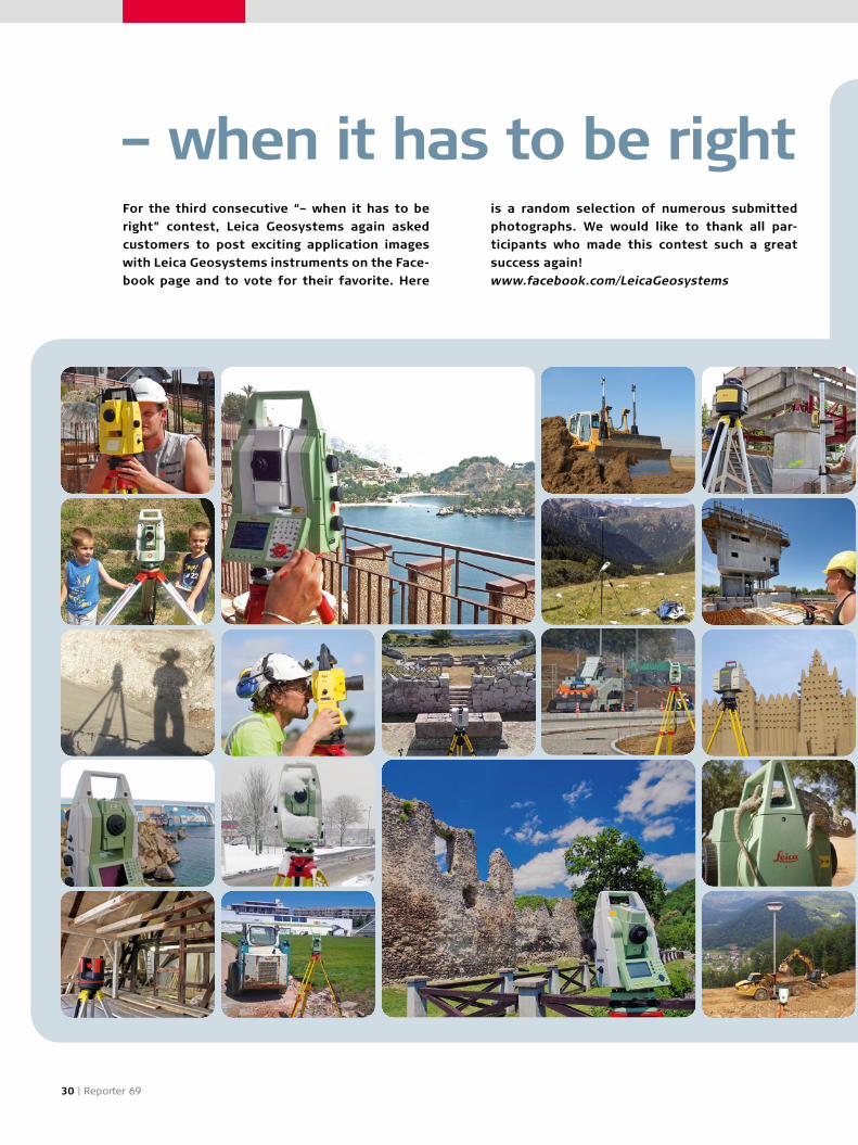
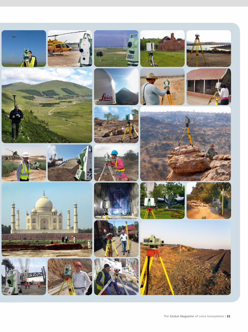
– when it has to be right For the third consecutive “– when it has to be
right” contest, Leica Geosystems again asked
customers to post exciting application images
with Leica Geosystems instruments on the Face-
book page and to vote for their favorite. Here
is a random selection of numerous submitted
photographs. We would like to thank all par-
ticipants who made this contest such a great
success again!
www.facebook.com/LeicaGeosystems
The Global Magazine of Leica Geosystems | 31

Leica Nova MS50 Make the right decision
Leica Nova MS50 – World`s First MultiStation
You only get a moment to make the right decision. So ultimate performance
and absolute reliability are critical. Our new Leica Nova MS50 MultiStation
combines total station, imaging and scanning technologies together to
create a unique solution that covers the complete workflow process from
capturing and visualising to deciding, acting on and delivering.
Leica Nova: a whole new dimension in measuring technology
www.leica-geosystems.com/nova
Illustrations, descriptions, and technical data are not binding. All rights reserved. Printed in Switzerland. Copyright Leica Geosystems AG, Heerbrugg, Switzerland, 2013. 741802en – 09.13 – RVA
Leica Geosystems AGHeinrich-Wild-StrasseCH-9435 HeerbruggPhone +41 71 727 31 31Fax +41 71 727 46 74www.leica-geosystems.com