The geometry of the Moineau pump - Technical University … · The geometry of the Moineau pump ......
14
The geometry of the Moineau pump Jens Gravesen Technical University of Denmark, Department of Mathematics 26 March 2008 Abstract The Moineau pump was invented in 1931 by the French engineer Ren´ e Moineau and exhibits an intriguing geometry. The original design is based on hypo- and epi- cycloids and all except one design has either cusps or less severe inflexion points with infinite curvature. By using the support function to represent planar curves it is possible to make an explicit analysis of a general design and we can show that points of infinite curvature are unavoidable. Key words: Moineau pump, envelope, support function. 1 Introduction The Moineau pump is an invention from 1931 by the French engineer Ren´ e Moineau, see [11]. The Moineau pump has two parts rotating relative to each other in an eccentric motion. The shapes in an axial cross section are in the original design based on epi- and hypo-cycloids. In 2006 the large Danish pump manufacturer Grundfos wanted an investigation of other possible designs and brought the problem to the 57th European Study Group with Industry held at the Technical University of Denmark. All but one of the classical designs possesses points with infinite curvature and it is of particular interest too see if that can be avoided. In a previous analysis of the scroll compressor [3] planar curves was represented by specifying the radius of curvature as a function of tangent direction. In the present work we specify the support as a function of normal direction. In both cases it is trivial to find a point with a given tangent or normal and this makes Email address: [email protected] (Jens Gravesen).
Transcript of The geometry of the Moineau pump - Technical University … · The geometry of the Moineau pump ......
The geometry of the Moineau pump
Jens Gravesen
Technical University of Denmark, Department of Mathematics
26 March 2008
Abstract
The Moineau pump was invented in 1931 by the French engineer Rene Moineauand exhibits an intriguing geometry. The original design is based on hypo- and epi-cycloids and all except one design has either cusps or less severe inflexion pointswith infinite curvature. By using the support function to represent planar curves itis possible to make an explicit analysis of a general design and we can show thatpoints of infinite curvature are unavoidable.
Key words: Moineau pump, envelope, support function.
1 Introduction
The Moineau pump is an invention from 1931 by the French engineer ReneMoineau, see [11]. The Moineau pump has two parts rotating relative to eachother in an eccentric motion. The shapes in an axial cross section are in theoriginal design based on epi- and hypo-cycloids. In 2006 the large Danish pumpmanufacturer Grundfos wanted an investigation of other possible designs andbrought the problem to the 57th European Study Group with Industry heldat the Technical University of Denmark. All but one of the classical designspossesses points with infinite curvature and it is of particular interest too seeif that can be avoided.
In a previous analysis of the scroll compressor [3] planar curves was representedby specifying the radius of curvature as a function of tangent direction. In thepresent work we specify the support as a function of normal direction. In bothcases it is trivial to find a point with a given tangent or normal and this makes
Email address: [email protected] (Jens Gravesen).

C2
C1
H2
P 6?δ
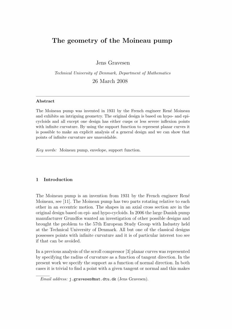
Fig. 1. The circle C1 rolls inside the circle C2 and the point P rolls back and forthon the diameter H2. To the right P and H2 are offset with δ.
it possible to get closed analytical expressions for the envelope of a movingcurve.
The support function is a classical tool in convex geometry [2] and was firstsuggested for use in geometric design by M. Sabin in 1974 [12]. Lately therehas been renewed interest in this representation [1,5,7,10,13,14]. Using thesupport function it is possible to analyse a general design and show thatinfinite curvature can not be avoided.
The paper is organised as follows. In Section 2 we introduce the original designsand explain how the pump works. In Section 3 we introduce the representationby the support function and give some properties of the representation. InSection 4 we analyse a general design, show that points of infinite curvaturecan not be avoided and give a few examples of new designs.
2 The original design
If a circle C1 with radius 1 rolls inside a circle Cn of radius n then a fixedpoint P on C1 traces a hypo-cycloid Hn with n cusps, see Fig. 3. In the casewhere n = 2 the hypo-cycloid is simply a diameter of C2 traced twice, oncein each direction, see Fig. 1. The rolling of C1 inside C2 also defines a motionin the plane and under this motion the point P moves along H2. If we offsetboth P and H2 with the same amount δ we obtain the rotor, a circle, movingback and forth in the stator, two parallel lines with semicircles attached at theends. The picture is a horizontal section in the pump and the areas to eachside of the rotor are sections in two pump chambers.
To construct the pump we now lift the right hand picture in Fig. 1 to horizontalplanes z = constant, see Fig. 2 to the left. We then roll each copy of the circleC1, to which the rotor is attached, a distance proportional to the height z, seethe second picture in Fig. 2. Finally we rotate each horizontal plane, with boththe rotor and the stator, such that all copies of the circle C1 are back to theoriginal position, see the third picture in Fig. 2. The stator is now formed by
2

Fig. 2. The construction of the pump is illustrated in the first three pictures andthe pumping in the last two pictures.
the thick “rounded rectangles”, the rotor is formed by the thick small circles,and the space in between forms two series of pump chambers. In Fig. 2 thehorizontal sections in one of the pump chambers are coloured in gray but onlya portion corresponding to half the height of a pump chamber is shown, (anyother portion can be found by symmetry). As all copies of C1 now are aboveeach other they form a cylinder as do the copies of C2. If the C1 cylinder nowrolls inside the C2 cylinder the thick small circles moves back and forth insidethe “rounded rectangles”. As we see from the difference between the thirdand the last picture this has same effect as a vertical translation followed by arotation, i.e., the pump chambers are moved up (or down) by a screw motion.For more pictures and animations, see [8,9].
2.1 The n + 1:n hypo-cycloid construction
Consider Fig. 3. We have three circles C1, Cn and Cn+1 with radii 1, n, and n+1respectively. Rolling C1 inside Cn and Cn+1 produces the two hypo-cycloids Hn
and Hn+1 respectively. Now consider the motion generated by letting Cn rollinside Cn+1 and let Hn follow the motion. It is easily seen that Hn+1 is (part of)the envelope for this moving curve. Furthermore, a straightforward calculationshows that the cusps of Hn stays on Hn+1 during the motion, see [6]. We cannow perform the same procedure as above. Lift the construction to horizontalplanes z = constant, roll each copy of Cn a distance proportional to z, androtate each horizontal plane such that the copy of Cn returns to its originalposition. This way n + 1 series of pump chambers are formed and when thecylinder formed by the copies of Cn rolls inside the cylinder formed by thecopies of Cn+1 the pump chambers move up or down by a screw motion, see[8,9].
3

C3
C2
C1
H3
H2
C4
C3
C1
H4
H3
C5
C4
C1
H5
H4
3:2 4:3 5:4
Fig. 3. Above the n + 1:n hypo-cycloid construction for n = 2, 3, 4. Below offsets ofthe same constructions. In the 3:2 construction we have zoomed in on a point wherea semicircle connects to the offset H3. The zoom uses different scales in the x andy direction.
In the patent [11] the construction is offset, probably to avoid the cusps. Ifan offset of a curve passes through a centre of curvature, i.e., intersects theevolute, then a cusp is formed. So to avoid cusps a curve can at most be offsetout to the minimum radius of curvature. The hypo-cycloids have zero radiusof curvature at the cusps so even though the offset is visually fine the offsetsdo have cups, see Fig. 3.
2.2 The n + 1:n epi-cycloid construction
Consider Fig. 4. We have three circles C ′
1, Cn and Cn+1 with radii 1, n, and n+1respectively. Rolling C ′
1 outside Cn and Cn+1 produces the two epi-cycloids En
and En+1 respectively. Now consider the motion generated by letting Cn rollinside Cn+1 and let En follow the motion. As in the previous cases En+1 is(part of) the envelope for this moving curve and the cusps of En+1 stays onEn during the motion, see [6]. A pump is constructed by the same procedureas in the hypo-cycloid case and n + 1 series of pump chambers are formed.Once again the cusps of a epi-cycloid has infinite curvature, so an offset hascusps too, as is clearly seen in Fig. 4.
4

C2
C1
C ′
1
E2
E1
C3
C2
C ′
1
E3
E2C4
C3
C ′
1
E4
E3
2:1 3:2 4:3
Fig. 4. Above the n + 1:n epi-cycloid construction for n = 1, 2, 3, below offsets.
C4
C2
C1
H4
E4
E2
H2
C6
C4
C1
H6
E6
E4
H4
C8
C6C1
H8
E8
E6
H6
A1
A2A2
A3
A3
A4
2:1 3:2 4:3
Fig. 5. The construction consisting of alternating arcs of hypo- and epi-cycloids.
2.3 The n + 1:n hypo-epi-cycloid construction
Consider Fig. 5. We have three circles C1, C2n, C2n+2 with radii 1, 2n, and2n + 2 respectively. If we take every second arc of the hypo-cycloid H2n andevery second arc of the epi-cycloid E2n we obtain a curve An consisting ofalternating arcs of hypo- and epi-cycloids. Each of these arcs are obtained byrolling C1 on the inside or the outside of C2n. We now let An follow the motiongenerated by letting C2n roll inside C2n+2. It can be shown that the outer part
5
of the envelope is An+1, that the tangents agree at each point in A2n ∩ An+1,and that there in general are n+1 points of contact except at specific instanceswhere two points of contacts come together, see [6]. By the same procedureas in the case hypo-cycloid or epi-cycloids, n + 1 series of pump chambers areformed and when the cylinder formed by the copies of C2n rolls inside thecylinder formed by the copies of C2n+2 the pump chambers move up or downby a screw motion, see [8,9]. This construction is without cusps but there aren inflexion points on An and here the curvature is infinite.
3 The support function
We first introduce a rotating frame (e, f) and the rotation matrix R,
e(φ) =
cos φ
sin φ
, f(φ) =
− sin φ
cos φ
, R(φ) =
cos φ − sin φ
sin φ cos φ
. (1)
Now let h : R → R be a real C2 function and consider the parametrisation
x(φ) = h(φ) e(φ) + h′(φ) f(φ). (2)
Differentiation yields x′(φ) = (h(φ) + h′′(φ)) f(φ) so x is regular if and only if
ds
dφ= h(φ) + h′′(φ) 6= 0. (3)
In that case the tangent is t = ±f(φ) and the normal is n = e(φ) 1 . Hence
h = x · f = x · n = distance from origo to the tangent line. (4)
That is, h is the support function for the curve parametrised by x. We have
d2x
ds2=
dt
ds=
dφ
ds
dt
dφ= (h + h′′)−1 f ′ = −(h + h′′)−1 e. (5)
We see that if h is a Ck function with k ≥ 2 and satisfying (3) then theparametrisation by arc length is Ck even though the parametrisation (2) isonly Ck−1. We also see that the signed radius of curvature is given by
ρ =ds
dφ= h(φ) + h′′(φ). (6)
Any planar curve with non vanishing curvature, i.e., without inflexion points,can be given as (2). If h is the support function of curve x then the rotated
1 If ρ > 0 then (t,n) = (f , e) is a negatively oriented basis
6

curve R(t)x has the support function φ 7→ h(φ−t), the translated curve x+a
has the support function φ 7→ h(φ) + a · e(φ), and the scaled curve cx has thesupport function ch, see [1,5,7,10,12–14].
We can not use the normal direction as a parameter across an inflexion point,but the modification in [4] allows us that.
Theorem 1 Consider an ordinary inflexion point (x0, y0) with curvature κ =κ1s + 1
2κ2s
2 + O(s3), where s is arc length and κ1 > 0. Denote the normal
direction by φ and let φ0 be the normal direction at the inflexion point. We
can introduce a parameter u such that u2 = φ − φ0 and the support function
can be written
h = x0 + y0u2 +
2
3
√
2
κ1
u3 + O(u4). (7)
Furthermore,
dh
dφ= y0 +
√
2
κ1
u + O(u2) andd2h
dφ2=
√
1
2κ1
1
u+ O(1). (8)
Proof. By a rotation we may assume that φ0 = 0. Then we have
dφ
ds= κ = κ1s +
κ2
2s2 + O(s3) and u2 = φ =
κ1
2s2 +
κ2
6s3 + O(s3).
Thus
s =
√
2
κ1
u −κ2
3κ21
u2 + O(u3), (9)
and
cos(φ) = 1 −1
8κ2
1s4 −
1
12κ1κ2s
5 + O(s6), sin(φ) =1
2κ1s
2 +1
6κ2s
3 + O(s4).
The curve can now be parametrised as
x =∫
t ds =∫
f(φ) ds =
x0 −16κ1s
3 − 124
κ2s5 + O(s5)
y0 + s − 140
κ21s
5 + O(s6)
.
Finally, the support function can be written
h = x · n = x · e(φ) = x0 +y0κ1
2s2 +
(
2κ1 + y0κ2
6
)
s3 + O(s4).
Substituting (9) into this expression shows (7). Using that ddu
= 2u ddφ
, equa-
tions (8) is a now a straightforward calculation. 2
7

4 General designs
We consider designs as in Fig. 5, i.e., designs consisting of arcs with alternatingsigns of curvature. We start with one positively curved arc of the rotor. Thisarc is then moved around by the motion generated by a circle rolling insideanother circle and we find the stator as the envelope of this moving curve.Then we reverse the viewpoint and consider the rotor as fixed while the statoris moving. Now the full rotor can be found as an envelope of this new movingcurve.
The motion generated by rolling a circle of radius b inside a circle of radius ais given by
x 7→ R(t)x + c e(αt), (10)
where c = a − b and α = b/(b − a). In particular, if we have a circle of radiusn rolling inside a circle of radius n + 1 then c = 1 and α = −n. Observe thatα < 0 if a > b. Now consider the motion of the curve (2),
X(φ, t) = R(t)x(φ) + c e(αt) = h(φ) e(φ + t) + h′(φ) f(φ + t) + c e(αt). (11)
We have a point on the envelope if and only if the velocity and the tangentare parallel. The partial derivatives of X are
∂X
∂φ= (h(φ) + h′′(φ)) f(φ + t), (12)
∂X
∂t= h(φ) f(φ + t) − h′(φ) e(φ + t) + αc f(αt). (13)
So we have a point on the envelope if and only if ∂X/∂t is orthogonal toe(φ + t), i.e., if and only if
0 =∂X
∂t· e(φ + t) = −h′(φ) + cα sin(φ + t − αt) (14)
or
sin(φ + (1 − α)t) =h′(φ)
cα. (15)
We can solve this equation with respect to t and obtain the complete solution
tσ,k =2kπ + 1−σ
2π + σ arcsin
(
h′(φ)cα
)
− φ
1 − α, σ = ±1, k ∈ Z. (16)
The value of k only matters in a few instances, so in the following we will justwrite tσ. Observe that
cos(φ + (1 − α)tσ) = cos
(
1 − σ
2π + σ arcsin
(
h′(φ)
cα
))
= σ
√
√
√
√1 −
(
h′(φ)
cα
)2
.
(17)
8

The normal of the envelope X(φ, tσ) is the normal of x(φ) rotated throughthe angle tσ, i.e., it is e(φ + tσ). So the normal direction of the envelope is
φσ = φ + tσ =1
1 − α
(
2kπ +1 − σ
2π + σ arcsin
(
h′(φ)
cα
)
− αφ
)
, (18)
and the derivative with respect to φ is
dφσ
dφ=
σh′′(φ) − cα2
√
1 −(
h′(φ)cα
)2
(1 − α)cα
√
1 −(
h′(φ)cα
)2. (19)
The support function of the envelope is hσ = X(φ, tσ) · e(φσ) which becomes
hσ = h(φ) + c cos(φσ − αtσ) = h(φ) + σc
√
√
√
√1 −
(
h′(φ)
cα
)2
. (20)
The first derivative with respect to normal direction is
dhσ
dφσ
= h′(φσ − tσ)
(
1 −dtσdφσ
)
− c sin(φσ − αtσ)
(
1 − αdtσdφσ
)
= h′(φ)
(
1 −dtσdφσ
)
− ch′(φ)
cα
(
1 − αdtσdφσ
)
=α − 1
αh′(φ), (21)
and the second derivative is
d2hσ
dφ2σ
=α − 1
αh′′(φ)
(
dφσ
dφ
)
−1
=c(1 − α)2h′′(φ)
√
1 −(
h′(φ)cα
)2
−σh′′(φ) + cα2
√
1 −(
h′(φ)cα
)2. (22)
If we interchange what is moving and what is fixed and reverse the timethen we just have to interchange a and b. Then c is replaced with −c and αwith 1 − α. Making the appropriate modifications to (18) we find the normaldirections
φσ,µ = φ +1
α
(
(
2ℓ − 2k +σ − µ
2
)
π + (µ − σ) arcsin
(
h′(φ)
cα
))
. (23)
The support functions are
hσ,µ = h(φ) + (σ − µ)c
√
√
√
√1 −
(
h′(φ)
cα
)2
, (24)
9
and the first and second derivative are
dhσ,µ
dφσ,µ
= h′(φ), (25)
d2hσ,µ
dφ2σ,µ
=h′′(φ)cα2
√
1 −(
h′(φ)cα
)2
(µ − σ)h′′(φ) + cα2
√
1 −(
h′(φ)cα
)2. (26)
We collect the information in the following theorem
Theorem 2 Let a positively curved arc of the rotor have the support function
φ 7→ h(φ) and let the motion be generated by a circle of radius n rolling inside
a circle of radius n + 1, where n ∈ N. Let
φ1(φ) −1
n + 1(nφ − arcsin(h′(φ)/n)) ,
φ−1(φ) =1
n + 1(π + nφ + arcsin(h′(φ)/n)) ,
φ−1,1(φ) = φ +1
n(π − 2 arcsin(h′(φ)/n)) ,
and
h1(φ) = h(φ) +1
n
√
n2 − (h′(φ))2,
h−1(φ) = h(φ) −1
n
√
n2 − (h′(φ))2,
h−1,1(φ) = h(φ) −2
n
√
n2 − (h′(φ))2.
Then the positively and negatively curved arcs of the rotor have the support
functions
φ 7→ h(φ + 2kπ/n), φ 7→ h−1,1
(
φ−1−1,1(φ + 2kπ/n)
)
, k = 0, . . . , n − 1,
respectively, and the positively and negatively curved arcs of the stator have
the support functions
φ 7→ h1
(
φ−11 (φ + 2kπ/n)
)
, φ 7→ h−1
(
φ−1−1(φ + 2kπ/n)
)
, k = 0, . . . , n,
respectively. We can parametrise the arcs as
x(φ) = h(φ) e(
φ + 2kπn
)
+ h′(φ) f(
φ + 2kπn
)
,
x−1,1(φ) = h−1,1(φ) e(
φ−1,1(φ) + 2kπn
)
+ h′(φ) f(
φ−1,1(φ) + 2kπn
)
,
x1(φ) = h1(φ) e(
φ1(φ) + 2kπn+1
)
+n + 1
nh′(φ) f
(
φ1(φ) + 2kπn+1
)
,
x−1(φ) = h−1(φ) e(
φ−1(φ) + 2kπn+1
)
+n + 1
nh′(φ) f
(
φ−1(φ) + 2kπn+1
)
.
10

A straightforward calculation shows that
ρσ = ρ −
(
h′′ − σcα
√
1 −(
h′
cα
)2)2
h′′ − σcα2
√
1 −(
h′
cα
)2, (27)
ρσ,−σ = ρ − 2(h′′)2 + c2α2 − (h′)2 − 2σch′′
√
1 −(
h′
cα
)2
2h′′ − σcα2
√
1 −(
h′
cα
)2. (28)
We will now analyse the situation at the endpoints of the arcs of the horizontalsections of the pump.
Theorem 3 Consider a Moineau pump design where the horizontal sections
of both the stator and rotor consists of smooth arcs with alternating strictly
positive and strictly negative curvature in the interior. If the support function
of the positively curved arc of the rotor either has an expansion
h = h0 + h1(φ − φ0) +hm
m!(φ − φ0)
m + O((φ − φ0)m+1), (29)
where hm 6= 0, or an expansion
h = h0 + h1u2 +
2h3
3u3 +
h4
2u4 + O(u5), (30)
where u2 = φ − φ0 and h3 6= 0. Then there are points with infinite curvature
in the design.
Proof. As the arcs of the stator, with support functions h1 and h−1 respec-tively, have to connect, the normal directions φ1 and φ−1 have to agree at theendpoints. Hence (h′)2 = c2α2 at the endpoints. By a rotation we may assumethat φ = 0 at the endpoint we consider.
First we consider the case (29). If m = 2 then it is easily seen that
ρσ = ρ −h2
2 + O(φ1/2)
h2 + O(φ1/2)→ ρ − h2 = h0, for φ → 0. (31)
If m ≥ 4 then we have
ρσ = ρ −c2α2 −2hm
h1(m−1)!φm−1 + O (φm+1)
−σcα2√
−2hm
h1(m−1)!φ
m−1
2 + O(
φm+1
2
) → ρ, for φ → 0. (32)
11
If m = 3 and h3 6= −α2h1 then we have
ρσ = ρ −
(
h3 − σcα√
−h3/h1
)2φ2 + O(φ3)
(
h3 − σcα2√
−h3/h1
)
φ + O(φ2)→ ρ, for φ → 0. (33)
Finally, if m = 3 and h3 = −α2h1 then we obtain
ρ−1,1 = ρ +(α2 − 1)α4c2φ2 + O(φ3)
α2h1φ + O(φ2)→ ρ, for φ → 0. (34)
We now consider the case (30). As ddu
= 2u ddφ
we have
dh
dφ= h1 + h3u + h4u
2 + O(u3) andd2h
dφ2= h3
1
u+ h4 + O(u).
Substituting this into (27) yields
ρσ = h0 + O(u) → h0, for u → 0. (35)
As ρ1 ≥ 0 and ρ−1 ≤ 0, we can conclude that ρ1 = ρ−1 = 0 at the endpoint ofthe arcs of the stator in the cases (31), (32), (33), and (35). Similar ρ ≥ 0 andρ−1,1 ≤ 0 so in the case (34) we have ρ−1,1 = ρ = 0 at the endpoint of arcs ofthe rotor. In all cases the design has points of infinite curvature. 2
4.1 Examples
We will consider a deformation of the 3:2 hypo-epi-cycloid design. We let c = 1and α = −2. An epi-cycloid arc of the rotor has the support function
h(φ) = 3 cos
(
2φ
3
)
, h′(φ) = −2 sin
(
2φ
3
)
, h′′(φ) = −4
3cos
(
2φ
3
)
,
with φ ∈[
−4π3
, 4π3
]
. If we preserve the values of h, h′, and h′′ at the endpointsthen we consider deformations h + η, where
η :[
−4π
3,4π
3
]
→ R, with η(
±4π
3
)
= η′
(
±4π
3
)
= η′′
(
±4π
3
)
= 0.
One possibility is
η(φ) = cos3
(
2φ
3
) (
a0 +N
∑
ℓ=1
(
aℓ cosℓ
(
2φ
3
)
+ bℓ sinℓ
(
2φ
3
)))
.
See Figure 6 for a few examples of such deformations.
12
–5
–4
–3
–2
–1
0
1
–2 –1 1 2
–6
–4
–2
2
–2 –1 1 2
–5
–4
–3
–2
–1
1
2
–2 –1 1 2
(a0, b1) =(
18 , 0
)
(a0, b1) =(
−12 , 0
)
(a0, b1) =(
0, 16
)
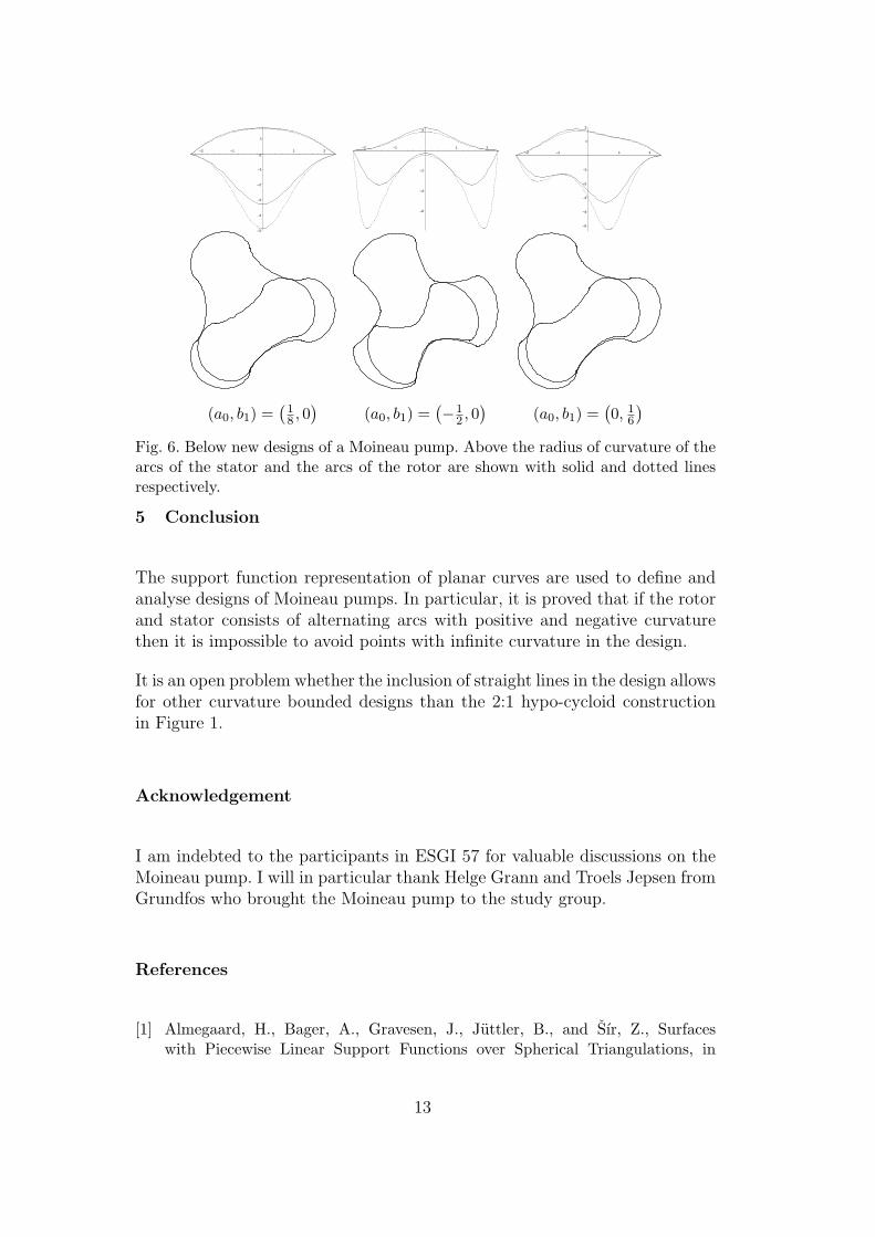
Fig. 6. Below new designs of a Moineau pump. Above the radius of curvature of thearcs of the stator and the arcs of the rotor are shown with solid and dotted linesrespectively.
5 Conclusion
The support function representation of planar curves are used to define andanalyse designs of Moineau pumps. In particular, it is proved that if the rotorand stator consists of alternating arcs with positive and negative curvaturethen it is impossible to avoid points with infinite curvature in the design.
It is an open problem whether the inclusion of straight lines in the design allowsfor other curvature bounded designs than the 2:1 hypo-cycloid constructionin Figure 1.
Acknowledgement
I am indebted to the participants in ESGI 57 for valuable discussions on theMoineau pump. I will in particular thank Helge Grann and Troels Jepsen fromGrundfos who brought the Moineau pump to the study group.
References
[1] Almegaard, H., Bager, A., Gravesen, J., Juttler, B., and Sır, Z., Surfaceswith Piecewise Linear Support Functions over Spherical Triangulations, in
13

Mathematics of surfaces XII (Ralph Martin, Malcolm Sabin, Joab Winkler,eds.), Springer Verlag, 2007, pp. 42–63.
[2] Bonnesen, T. and Fenchel, W., Theory of convex bodies. BCS Associates,Moscow, Idaho, 1987.
[3] Gravesen, J. and Henriksen, C., The geometry of the scroll compressor, SIAM
Review 43, 113–126 (2001).
[4] Gravesen, J., The Intrinsic Equation of Planar Curves and G2 HermiteInterpolation. In Seattle Geometric Design Proceedings (Miriam Lucian andMike Neamtu eds.) Nashboro Press, 2004, pp. 295–310.
[5] Gravesen, J., Surfaces parametrised by the normals, Computing 79, 175–183(2007).
[6] Gravesen, J. et al., Mathematical problems for Moineau pumps, 2006, in Final
report for the 57th European Study Group with Industry, http://www2.mat.dtu.dk/ESGI/57/report/grundfos.pdf
[7] Gravesen, J., Juttler, B., and Sır, Z., Approximating Offsets of Surfaces by usingthe Support Function Representation, in Progress in Industrial Mathematics at
ECMI 2006 (Bonilla, L.L.; Moscoso, M.; Platero, G.; Vega, J.M. Eds.) SpringerVerlag, 2007, pp. 719–723.
[8] Gravesen, J., The Moineau Pump, Technical University of Denmark, 2007,http://www2.mat.dtu.dk/people/J.Gravesen/MoineauPump/
[9] Gravesen, J., Spherical curves for the design of conical Moineau pumps, SIAMActivity Group in Geometric Design, Problem Section, 2008, http://www.ifi.uio.no/siag/problems/gravesen/
[10] Gravesen, J., Juttler, B., and Sır, Z., On rationally supported surfaces, Comp.
Aided Geom. Design, to appear.
[11] R. J. L. Moineau, Gear Mechanism, US-Patent no. 1 892 217, 1931.
[12] Sabin, M., A Class of Surfaces Closed under Five Important GeometricOperations, Technical report VTO/MS/207, British aircraft corporation, 1974,http://www.damtp.cam.ac.uk/user/na/people/Malcolm/vtoms/vtos.html
[13] Sır, Z., Gravesen, J., and Juttler, B., Computing Minkowski sums via SupportFunction Representation, in Curve and Surface Design: Avignon 2006, (PatricChenin, Tom Lyche, and Larry Schumaker eds.) Nashboro Press, Brentwood2007, 244–253.
[14] Sır, Z., Gravesen, J., and Juttler, B., Curves and surfaces represented bypolynomial support functions, Theoretical Computer Sciences, 392, 141–157,(2008).
14