THE GENERATION OF MECHANICALLY MIXED … GENERATION OF MECHANICALLY MIXED LAYERS (MMLS) DURING...
5
THE GENERATION OF MECHANICALLY MIXED LAYERS (MMLS) DURING SLIDING CONTACT Aadarsh Mishra 1 * *Corresponding Author: Aadarsh Mishra, [email protected] In unlubricated and boundary lubricated sliding, materials touch only at a restricted numberof isolated, typically microscopically small ‘contact spots’ that occupy but a small fraction of the macroscopic interfacial area.The intermittent local shear strains at thecontact spots in the course of sliding are very large. This behavior has been simulated, both for dry sliding and lubrication, by means of stacked foils of pure copper and silver shearedunder high superimposed pressure in a Bridgman-anvil apparatus. Strain hardening curves were obtained and the samples, now equivalentto material at wear tracks and specifically ‘echanically Mixed Layers (MMLs), were examined microscopically by means of a variety oftechniques. Keywords: Contact spots, Mechanically mixed layers, Bridgman-anvil apparatus INTRODUCTION In unlubricated or boundary-lubricated sliding, the normal force between two sides P, is almost always supported at only a restricted number of ‘contact spots’ at which thelocal pressure compares with the hardness of the softer side (H) and whose total area (A) is controlled by local plasticdeformation so that P = AH. As the contact spots move, the interfacialzone between the two materials becomes severelysheared. In this zone there occurs very fine mixingbetween the two sliding metals. In connection with the local shear strains, numerous studies have been ISSN 2278 – 0149 www.ijmerr.com Vol. 3, No. 3, July 2014 © 2014 IJMERR. All Rights Reserved Int. J. Mech. Eng. & Rob. Res. 2014 1 Department of Mechanical Engineering, Manipal Institute of Technology, Manipal University, Manipal, Karnataka 576104, India. performed on sliding interfaces. Dautzenberg (Dautzenberg, 1980) embedded an aluminum foil marker in a copper pin, atright angles to the interface. After sliding the pin on a rotating steel surface and examining the cross-section of the pin, he found that the marker had been sheared with increasingintensity from the bulk towards the surface. This was indicatedby a gradual turning of the aluminum foil marker parallelto the sliding direction of the copper pin. The demonstratedshape of the aluminum marker illustrates the verylarge shears that commonly develop at the tribo-interfacesof ductile materials. For another example, Ives (Ives, 1979) foundafter abrading copper with Research Paper
Transcript of THE GENERATION OF MECHANICALLY MIXED … GENERATION OF MECHANICALLY MIXED LAYERS (MMLS) DURING...

578
Int. J. Mech. Eng. & Rob. Res. 2014 Aadarsh Mishra, 2014
THE GENERATION OF MECHANICALLY MIXEDLAYERS (MMLS) DURING SLIDING CONTACT
Aadarsh Mishra1*
*Corresponding Author: Aadarsh Mishra,[email protected]
In unlubricated and boundary lubricated sliding, materials touch only at a restricted numberofisolated, typically microscopically small ‘contact spots’ that occupy but a small fraction of themacroscopic interfacial area.The intermittent local shear strains at thecontact spots in the courseof sliding are very large. This behavior has been simulated, both for dry sliding and lubrication,by means of stacked foils of pure copper and silver shearedunder high superimposed pressurein a Bridgman-anvil apparatus. Strain hardening curves were obtained and the samples, nowequivalentto material at wear tracks and specifically ‘echanically Mixed Layers (MMLs), wereexamined microscopically by means of a variety oftechniques.
Keywords: Contact spots, Mechanically mixed layers, Bridgman-anvil apparatus
INTRODUCTIONIn unlubricated or boundary-lubricated sliding,the normal force between two sides P, is almostalways supported at only a restricted numberof ‘contact spots’ at which thelocal pressurecompares with the hardness of the softer side(H) and whose total area (A) is controlled bylocal plasticdeformation so that P = AH.
As the contact spots move, theinterfacialzone between the two materialsbecomes severelysheared. In this zone thereoccurs very fine mixingbetween the two slidingmetals. In connection with the local shearstrains, numerous studies have been
ISSN 2278 – 0149 www.ijmerr.comVol. 3, No. 3, July 2014
© 2014 IJMERR. All Rights Reserved
Int. J. Mech. Eng. & Rob. Res. 2014
1 Department of Mechanical Engineering, Manipal Institute of Technology, Manipal University, Manipal, Karnataka 576104, India.
performed on sliding interfaces. Dautzenberg(Dautzenberg, 1980) embedded an aluminumfoil marker in a copper pin, atright angles tothe interface. After sliding the pin on a rotatingsteel surface and examining the cross-sectionof the pin, he found that the marker had beensheared with increasingintensity from the bulktowards the surface. This was indicatedby agradual turning of the aluminum foil markerparallelto the sliding direction of the copperpin. The demonstratedshape of the aluminummarker illustrates the verylarge shears thatcommonly develop at the tribo-interfacesofductile materials. For another example, Ives(Ives, 1979) foundafter abrading copper with
Research Paper
579
Int. J. Mech. Eng. & Rob. Res. 2014 Aadarsh Mishra, 2014
sand, that some of the sand hadbecomeembedded in the copper in what he called‘highly irregularsurface deformation’. Next,Rigney et al. (1986) found the same extremelystrong shear strain gradient adjacent to tribo-interfaces. Following are conclusionsregarding MMLs for the case of slidingbetween two materialsof comparablehardness.
• During unlubricated as well as solid andboundary lubricatedsliding, MML’s originatefrom the statistical movements of the smallasperities which from moment to momentform the load bearing ‘contact spots’. Heattransfer, electrical conduction, friction andwear arise atthose contact spots.
• MML’s form through the cumulativelyextremely largeshear strains and incidentalmixing between the two sidesthatstatistically occur at the contact spots undernormal pressures comparable to the localhardness of the softerside.
EXPERIMENTAL STUDIESThe study of actual contact spots is difficult notso much on account of their small area andshallow depth in thematerial but because theyare hidden from view. When inspectingwornsurfaces due to sliding contact, one cannottellwhere specifically the contact spots werelocated fromone moment to the next and evenless how long they lastedor how far they moved.Local conditions at contactspots, which causemechanical alloying and the formationofMMLs, involve the already discussed extensiveplasticdeformation and extremely large shearstains. A Bridgman-anvil apparatus wasemployed. Herein, foil disk samples areplaced between twopairs of anvils, one rotating
and the other stationary. The shear stainsachievable in this device are enormous.TheBridgman apparatus is an effective andefficient way of studying the behaviors ofmaterials under the conditions known to prevailat contact spots specifically, and at tribo-interfaces after substantial wear, in general.Bridgman invented his anvil apparatus in the1930s. Two disk samples are at positions Aand are sheared between stationary anvils Band the rotating platen C under appliedpressure P. The specific apparatus, in whichall of the experiments of the present andprevious cited research were done. Itismodified from the original Bridgman apparatusin order to permit continuous measurement ofboth sample thickness and applied torqueduring shearing so as to obtain the alreadyindicated stress-strain curves. Here theaverage shearstress is inferred from thetorque required to rotate the platenand thus tointernally shear the specimens. It is measuredby the load cell. The shear strain is determinedfrom the anvil rotation in conjunction with thesimultaneous thinning of the sheared samples.These same conditions also apply to thedeformation of interlocked plastic contactspots that inactual friction and wear leads tothe formation of MML’s. Because workhardening of the specimens increases theirshear strength during the simulation, thedesired conditionof non-slip sample/anvilcontact may not persist during the course ofan experiment. The higher is the appliednormal pressure, the larger the shear strainthat canbe imposed on the samples beforeslipping occurs. A minimal pressurecomparable to the beginning hardness of thesample is always required to obtainany interiorsample shearing at all. Increasing friction

580
Int. J. Mech. Eng. & Rob. Res. 2014 Aadarsh Mishra, 2014
between samples and anvils reduces theprobability ofslipping.
The average thickness h of the two samplesis monitored by the proximity probe whoseoutput voltage (Vp) varies linearly with distanceas:
h = CpVp
where Cp is the proximity probe constant.
Gradual thinning of the sample sets insimultaneously with the onset of interiorshearing, but not necessarily directly onactivation of anvil rotation. Experimentally, anydelay of the thinning and extrusion of materialin the sample is thus due to slippage whether
between the anvils and the sample surface orbetween layers within the samples. Whetheranvil-sample slipping occurred can beascertained by viewing the specimen surfacesunder an optical microscope and notingwhether the specimen surface morphologymatches that of the adjacent anvil. Scoringmarks on the sample show when slipping hasoccurred.
This effect poses an additional problem tothe inherent in homogeneous strain when tryingto quantify the amount of strain.
Figure 1: Pressure is Applied as Indicatedby the Arrows Labeled P. Two SimilarSamples are Placed Symmetrically
Between the Two B and A Anvil Pairs
Figure 2: Schematic of the Formationof MML’s at the Interface Between Two
Metals
581
Int. J. Mech. Eng. & Rob. Res. 2014 Aadarsh Mishra, 2014
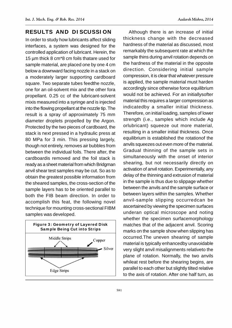
RESULTS AND DISCUSSIONIn order to study how lubricants affect slidinginterfaces, a system was designed for thecontrolled application of lubricant. Herein, the15 µm thick 8 cm*8 cm foils thatare used forsample material, are placed one by one 4 cmbelow a downward facing nozzle in a stack ona moderately larger supporting cardboardsquare. Two separate tubes feedthe nozzle,one for an oil-solvent mix and the other forapropellant. 0.25 cc of the lubricant-solventmixis measured into a syringe and is injectedinto the flowing propellant at the nozzle tip. Theresult is a spray of approximately 75 mmdiameter droplets propelled by the Argon.Protected by the two pieces of cardboard, thestack is next pressed in a hydraulic press at80 MPa for 3 min. This pressing largely,though not entirely, removes air bubbles frombetween the individual foils. There after, thecardboardis removed and the foil stack isready as a sheet material from which Bridgmananvil shear test samples may be cut. So as toobtain the greatest possible information fromthe sheared samples, the cross-section of thesample layers has to be oriented parallel toboth the FIB beam direction. In order toaccomplish this feat, the following noveltechnique for mounting cross-sectional FIBMsamples was developed.
Although there is an increase of initialthickness change with the decreasedhardness of the material as discussed, mostremarkably the subsequent rate at which thesample thins during anvil rotation depends onthe hardness of the material in the oppositedirection. Considering initial samplecompression, it is clear that whatever pressureis applied, the sample material must hardenaccordingly since otherwise force equilibriumwould not be achieved. For an initiallysoftermaterial this requires a larger compression asindicatedby a smaller initial thickness.Therefore, on initial loading, samples of lowerstrength (i.e., samples which include Agorlubricant) squeeze out more material,resulting in a smaller initial thickness. Onceequilibrium is established the rotationof theanvils squeezes out even more of the material.Gradual thinning of the sample sets insimultaneously with the onset of interiorshearing, but not necessarily directly onactivation of anvil rotation. Experimentally, anydelay of the thinning and extrusion of materialin the sample is thus due to slippage whetherbetween the anvils and the sample surface orbetween layers within the samples. Whetheranvil-sample slipping occurredcan beascertained by viewing the specimen surfacesunderan optical microscope and notingwhether the specimen surfacemorphologymatches that of the adjacent anvil. Scoringmarks on the sample show when slipping hasoccurred.The uneven shearing of samplematerial is typically enhancedby unavoidablevery slight anvil misalignments relativeto theplane of rotation. Normally, the two anvilswhileat rest before the shearing begins, areparallel to each other but slightly tilted relativeto the axis of rotation. After one half turn, as
Figure 3: Geometry of Layered DiskSample Being Cut into Strips
582
Int. J. Mech. Eng. & Rob. Res. 2014 Aadarsh Mishra, 2014
one anvil is fixed, during rotation thismisalignment causes a maximum pinchingeffect on one side of the samples where theanvils squeeze together, while on theoppositeside the pressure is at a relativeminimum. Due to this slight misalignment ofthe anvils during rotation, all of the measuredcurves exhibit some apparent shear strengthundulation that is periodic with the anvilrotation. Moreover, the discussed pinchingafter one half turn and then again after one anda half turn can cause a perforation in thesamples and thereby effectively end theexperiment. Contact spots arethe means bywhich materials in sliding contact becomeinterlocked at the interface and cause thestatistical strong shear. Initially, then, it isexpected that during ordinary sliding thetangential pull between interlocked spotscauses elongations in the form of easilyrecognizable ‘tongues’ which gradually refineand overlap into the lamellation that simulatesMML’s.
CONCLUSIONFrom this research, the following conclusionsemerge: (1) At least some types of adhesivewear result from shearing at tribo-interfaceswhich, beginning with interlocked contactspots, causes geometrice longations dubbed‘tongues.’ (2) Through a simple geometricdistortion of surface waviness, continuedshearing leads to fine lamellation of thesetongues.
ACKNOWLEDGMENTI would also like to dedicate this research workto my father late R S Mishra and mother K LMishra.
REFERENCES1. Bowden F P and Tabor D (1973), Friction:
An Introduction Tribology, Anchor Press/Doubleday, Garden City, New York.
2. Cai B, Kuhlmann-Wilsdorf D, Nelson R B,Rohatgi P K, Blau P J and Yust C S(Eds.), (1990), Tribology of CompositeMaterials, pp. 81-91, ASM International,Materials Park, OH.
3. Dautzenberg J H (1980), Wear, Vol. 60,p. 401.
4. Holm R (1967), Electrical Contacts:Theory and Application, 4th Edition,Springer, Berlin, New York.
5. Ives L K (1979), “Microstructural Changesin Copper Due to Abrasive”, Dry andLubricated Wear, p. 246, AMSE,Dearborn, MI.
6. Rigney D A, Naylor M G S, Divakar R andIves L K (1986), Mater. Sci. Eng., Vol. 81,pp. 409-425.
7. Uenishi K, Kobayaski K F, Ishihara K Nand Shingu P H (1991), Mater. Sci. Eng.A, Vol. 134, pp. 1342-1345.