![The GE;NE;RAL RADIO XP RIM NT R · 2 THE GENERAL RADIO EXPERIMENTER The new Electron 0 cilloo-raph (TYPE 687-A) include eep ir uit and power supp]y greatly implified typ of swe p](https://static.fdocuments.us/doc/165x107/5e8504b9fac42572523be586/the-general-radio-xp-rim-nt-r-2-the-general-radio-experimenter-the-new-electron.jpg)
The G N RAL RADIO EXPERIMENTER
8
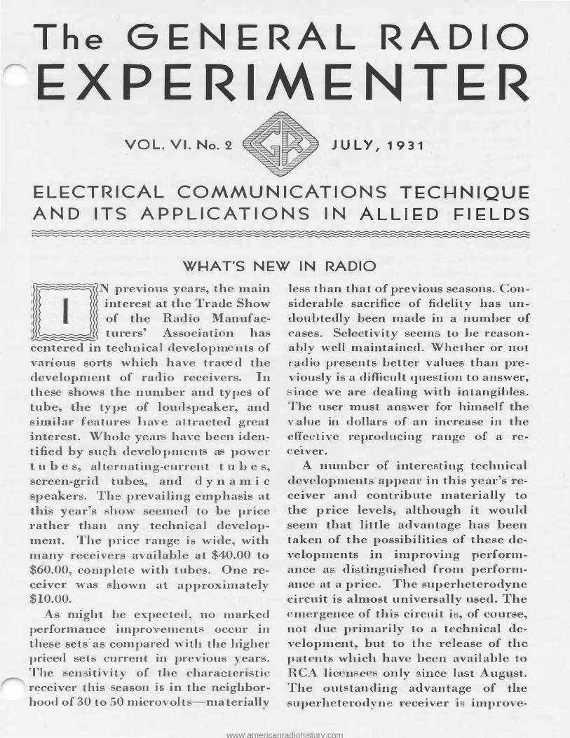
The G�N�RAL RADIO EXPERIMENTER VOL. VI. No. 2 JULY, 19 31 EL�CTRICAL COMMUNICATIONS TEC�NIQUE ALLIED FIELDS AND ITS APPLICATIONS IN WHAT'S NEW IN RADIO _. N previous years, the main I i nt erest at the Trade Show of the Radio Manuf ac- turers' sso ci a t · on has centered in te hn.ica 1 dev lopm nts of var·ous sorts which have trac d the development of radio recei vers . In thes e shows the nber and types of tube, the type of loudspea ker, and si ilar f ea t ure :ia e attracted great interest. Whole y ar have been iden- tified by su h devel pm en t a power t u b e s, alternating-curren t t u h e s, screen- g rid tube , and d y n a m i c speaker . Th prevailing e1nphasis at this year's l ow seemed to be price rather than any techni al develop- ment. The pri ce ran g e is wide, with many receivers available at $40.00 to $60.00, complete with tubes. One re- ce ver wa hown at approxin:i ately $10.00. As might be expected, no marked perf ormance i mpro ement occur in these sets· as compared ' ith the higher priced sets current previous years. The en iti ity of the chara teristic receiver this eas on i in the neighbor- hood of 30 to 50 microvolts-materially less than that of p revious seasons. Con- siderable sacrifice of fidel i ty has un- d oubtedly been made in a number of cases. Selectivity seem to be reason- ably well 1n.aintained. Whether or not radi o presents better val ues than pre- viously is a difficul t question to answer, ince we are dealing with intan.gibles. The user must an wer for himself the alue in dolla1 · s of an increase in the effective reprodu ing ra n ge of a re- e1 ver. A number of i nt ere ting technical development s appear i n this year 's re- ceiver and contribute materially to the price levels, although it would s eem that little advant a g e has been taken of the possibilities of these de - velopments in improving perform- ance a di tingui shed from perform- ance at a price. The superheterodyne circuit is almost universay used. The mergence of this circuit i , of course, not due primarily to a technical de- velopment but to th release of the patents which have been avai lable to RCA l i e n e onl y ii e la t ugust. The o ut t anding advantage of the superheterodyn. receiver i in:iprove- www.americanradiohistory.com
Transcript of The G N RAL RADIO EXPERIMENTER
The G�N�RAL RADIO
EXPERIMENTER VOL. VI. No. 2 JULY, 19 31
EL�CTRICAL COMMUNICATIONS TEC�NIQUE ALLIED FIELDS AND ITS APPLICATIONS IN
WHAT'S NEW IN RADIO ,____..DJ_______,N previous years, the main
I interest at the Trade Show of the Radio Manuf acturers' ssocia t ·on has
centered in te hn.ica 1 dev lopm nts of var·ous sorts which have trac d the development of radio receivers . In these shows the nUinber and types of tube, the type of loudspeaker, and si ilar fea ture :ia e attracted great interest. Whole y ar have been identified by su h devel pm en t a power t u b e s, alternating-curren t t u h e s, screen-grid tube , and d y n a m i c
speaker . Th prevailing e1nphasis at this year's l ow seemed to be price rather than any techni al development. The price range is wide, with many receivers available at $40.00 to
$60.00, complete with tubes. One rece ver wa hown at approxin:iately $10.00.
As might be expected, no marked performance impro ement occur in these sets· as compared ' ith the higher priced sets current in previous years. The en iti ity of the chara teristic receiver this eason i in the neighborhood of 30 to 50 microvolts-materially
less than that of previous seasons. Considerable sacrifice of fideli ty has undoubtedly been made in a number of cases. Selectivity seem to be reason.ably well 1n.ain.tained. Whether or not
radio presents better values than previously is a difficult question to answer,
ince we are dealing with intan.gibles. The user must an wer for himself the
alue in dolla1·s of an increase in the effective reprodu ing range of a re
e1 ver. A number of intere ting technical
developments appear in this year's receiver and contribute materially to the price levels, although it would
seem that little advantage has been taken of the possibilities of these developments in improving performance a di tinguished from performance at a price. The sup erheterodyne circuit is almost universally used. The
mergence of this circuit i , of course,
not due primarily to a technical development., but to th release of the patents which have been available to
RCA lie n e only ii e la t ugust. The o ut tanding advantage of the superheterodyn. receiver i in:iprove-
www.americanradiohistory.com
2 THE GENERAL RADIO EXPERIMENTER
ment in selectivity and, in particular, a gain in uniformity of selectivity over the tuning range of the receiver. The commercial models of receiv rs having this circuit do not seem to be any more sensitive than those of previous years using the tuned radiofrequency circuit.
Another development which i incorporated in a number of rec ivers is the so-called variable mu tube. This is a recently developed vacuUJll tube in wh"ch the amplification factor is a £unction of the signal voltage impressed on the tube, the amplification factor decreasing as the signal voltage is increa ed. The effect of thi tube is to limit increases in volume and to d e c r e a s e c r o s s t a l k a n d disto tion i n the radi ofrequency stages of the receiver.
nother technical development is the pentode or five-element power tube. This tube greatly increa es th power-handling capacities of a stage of amplification using a single tube and g reatly reduces the
cost of the audio amplifier for a given output. An increase in phonographic attachments and accessories i noti eable. large variety of automatic record changers of various t pes were on display. Home ��talkie" equipment was shown h a number of manufacturers.
he public interest in television is obviou ly intense. De elopments along this line· continue to progress slowly. Demonstrations of two types which are in operation in connection with regular broadcasts were given. The principal advance has been the increase in area of the re eiving s reen and a o the increase of the receiving field to the point where full leng h figures may
be reproduced. When one ponders on the prob able type of television program of t e future in the l ight of p resent audible b road ast programs, one wonders if the vast amount of time and effort being put into the development of televi ion could not be directed in a more useful and productive channel.
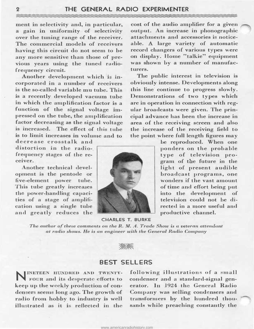
CHARLES T. BURKE The author of the e comments on the R. M. A. Trade Show is a veteran attendant
at radio shows. He is an engineer with the General Radio Company
BEST SELLERS
N ETEE H RED AND TWE T -
FO R and its de rat £fort to keep up the w kly produ tion of conden er seem long ago. The growth of radio from. hobby to industry is w 11 illu trated as it i reflected in th
foll o wi ng i l lu trat i o n of a mall condenser and a standard-signal generator. In 1924 th General Radio Company was selling cond nsers and tra form r by the hundred thousand while preaching constantly the
www.americanradiohistory.com
JULY, 1931-VOL. VI-No. 2 3
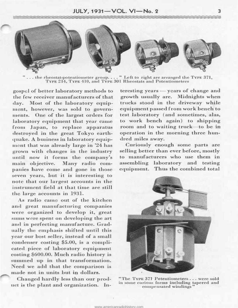
•• . . . the rheostat-potentiometer g1:oup .... " Left to right are arranged the TYPE 371, TYPE 214, TYPE 410, and TYPE 301 Rheostats and Potent"ometers
gasp I of better laboratory methods to the few receiver manufactui·ers of that day. Most of the laboratory equipm nt, however, was sold to governments. One of the largest orders for laboratory equipment that year came from Japan, to replace apparatus destroyed in the great Tokyo earthquake. A bu iness in. laboratory equipm nt that was already large in '24 has grown. with changes in the industry until now it forms the company's main objective. Many radio companies have come and gone in those
even year , hut it is interesting to note that our la1·gest accounts in the in.strum nt field at that time are still th large accounts in 1931.
s radio cam out of the kitchen and great manufacturing companies were organized to develop it, great sums w 1·e spent on developing the art and in perfecting manufacture. Gradually th emphasis shifted until this year our b st seller, instead of a small condenser costing $5.00, is a complicated piece of laboratory equipm.ent costing $600.00. Much radio history is
um.m ed up in that transformation. eed we add that the comparison i
made not in units but in. dollars.
Changed hardly less than our product is the plant and organization. In-
teresting years - y ars of change and growth usually are. Midnights when trucks stood in the driveway while equipment passed from work bench to test laboratory (and sometimes, alas, to work bench again) to shipping 1·oom and to waiting truck-to he in operation in the morning three hundred :miles away.
Curiously enough some parts are selling better than ever before, mostly to manufacturers who use them in assembling laboratory and testing equipm nt. Thus the combined total
••The TYPE 371 Potentiometers ... were sold in some curiou forms including tapered and
con1pcnsated ·windings"
www.americanradiohistory.com
4 THE GENERAL RADIO EXPERIMENTER
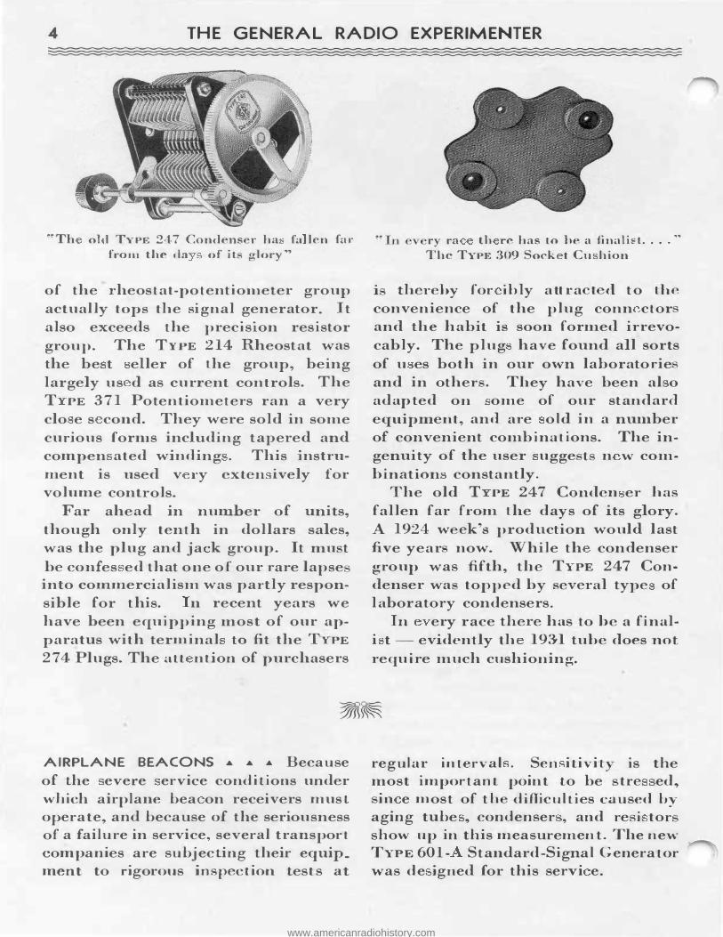
"Th ol l TYPE 247 Condens r ha fa len for from the da of it <Tlory"
of the 1·heostat-potentioJDeter group actual ly tops the signal generator. It also exceeds the prec1s1on resistor group. The TYPE 214 Rheostat was
the be t eller of the group, being largely us d as current controls. The T PE 371 Potentiometers ran a very clo e s cond. They were sold in some curious forn1s including tapered and compen ated winding . This instrument is used v ry exten ively for volume controls.
Far ahead in nuniber of units, though only tenth in dollars sales, was the plug and ja k group. It IIll.LSt
be confes ed that one of our rare lapse into commercialism was partly responsible for this. n recent years we have been equipping most of our apparatus with terminal to fit the TYPE 274 Plugs. The att ntion of purchasers
AIRPLANE BEACONS • • .a. Because of the evere ervice conditions under which airplane bea on receivers must operate, and because of the seriousness of a failure in service, several transport companies are subjecting their equip_ ment to rigorous inspection test s at
• 11 ry ra tJi re has to be a finalii: t. . . . "
The TYPE 309 ock t Cu h ion
i thereby for ibly attra t d to the convenience of the plug conn ctor and the habit is soon formed irrevocably. The plug have found all sorts of u es both in our own lahoratorie and in other . They have been al o adapted on ome of our standard equipment, and are old in a num.ber of convenient combinations. The ingenuity of the user ugge t n w combination constantly.
The old T PE 24 7 Con.den er has fallen far from the days of its glory. A 1924 w ek's production would last five year now. While th condenser group was fifth., the TYPE 24 7 Condenser wa topped by several type of laboratory condensers.
In ery race there has to he a final
i t - evidently th 193'1 tube does not require much cushioning.
regu l ar interval . Sen itivit is the most important point to be tre ed�
in e most of th difficulties caused by aging tube � condenser , and resi tor show up in this measurement . The new TYPE 601- Standard -Signal Generator was de igned for th is servi e.
www.americanradiohistory.com
JULY, 1931-VOL. VI-No. 2 5
Tl-IE CALI BRATED VOLTAGE DIVIDER 0 E of the mo t annoying jobs n
ounter d in a man Jaborator i� L h a t f hta ining ac urate Lati.c chara t ri tics of vacuum tube ual I it
on ist of varying a grid bia -b a
tapped battery , for in tan -ob er -
ing the value of thi bia on a voltmeter, and then measuring the plate
urrent. By the time t he grid voltmeter ha been read, and the voltage a justed to even values o as to make curve p1otting ea y, the vacuum tub may have aged omewhat and it characteristics changed. Where preci e and
TYPE 554 VOLTAGE
� Dl '°j, IDER
,
l ¥ t� $ ·"'-· ·' .
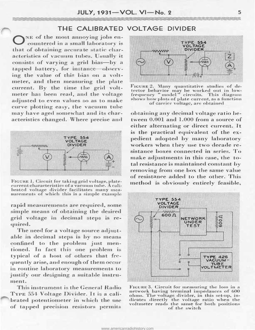
FIG RE 1. Cir nit for taking grid oltage, plat e
current charact ri tic of a vacuu1n tube. calibrat d ltage di ider fa ilitate many m asurement of w-hi h this is a imple xampl
rapid m a urement are required, some imple means of obtaining the de ired
grid voltage in de imal tep is required .
The need for a voltage source ad ju table in. decimal steps is by no mean
on.fined Lo the problem just mentioned. In fac t thi one problem i typical of a host of others that frequently arise, and enough of them oc ur
in routine laboratory measurements to
justify our de igning a suitable instrument.
Thi in tr m nt i t:he G n ral Radio TYPE 554 Voltage Di vider. It i a alibrated potentiometer in whi h the us of tapped prec j 1 n re i tor p rmit
F1G RE 2. Man quantitative tudi of d tector beha ior may be w-ork d out in low-frequ nc •• Jnod 1" ir uits. This diagram show. how plot o plate u.rr nt a a hm tion
of arri r oltage, ar obtained
obt ai n ing any decimal oltag ratio between. 0.001 and 1.000 from a ource of either alternating or direct current . It · s the practical equivalent of the expedient adopted by many laborator workers when t hey u e two decade resistance ho es conne ted in s rie . To
make adjustment in ·this ase, the total resistance i maintained con tan.t b
removing from one box ·the same value of resistan e added to the other. Thi method is obviously entirely feasible,
TYPE 554 VOLTAGE
DIVIDER.--------. I
I soon NETWORK
UNDER TEST ,
'IG RE 3. Ci rc uit for mea uring th network having terminal im pedan
� 0 0 U>
ohm . he oltag di id r, in thi t-up, in-dicate direct} th olt ag ratio when th
oltmeter read the same f r hoth position. of the with
www.americanradiohistory.com
6 THE GENERAL RADIO EXPERIMENTER
hut it has the disadvantages of being clumsy to manipulate and of requiring vigilance to make sure that the sum_ of the two resistances remains constant.
Four typical uses for the voltage divider are shown in the accompanying diagrams. Figure 1 represents the taking of vacuum-tube characteristics. Figure 2 shows how the heha vior of a detector tube may be investigated by the use of a low-frequency carrier. In the model circuit, Z has the same value (magnitude and phase angle) at the low frequency as the load circuit would have at the true carrier frequency. Inter-electrode capacitances in the tube are neglected, but even these may be simulated by suitably placed condensers of the proper value.
A way of measuring the insertion loss of a network is shown in Figure 3. This gives the loss directly as a voltage ratio which may be converted into decibels if desired. If the voltage divider be placed in the v a c u u m -t u b e v o l t m et er circuit, the arrangement becomes suitable for mea-
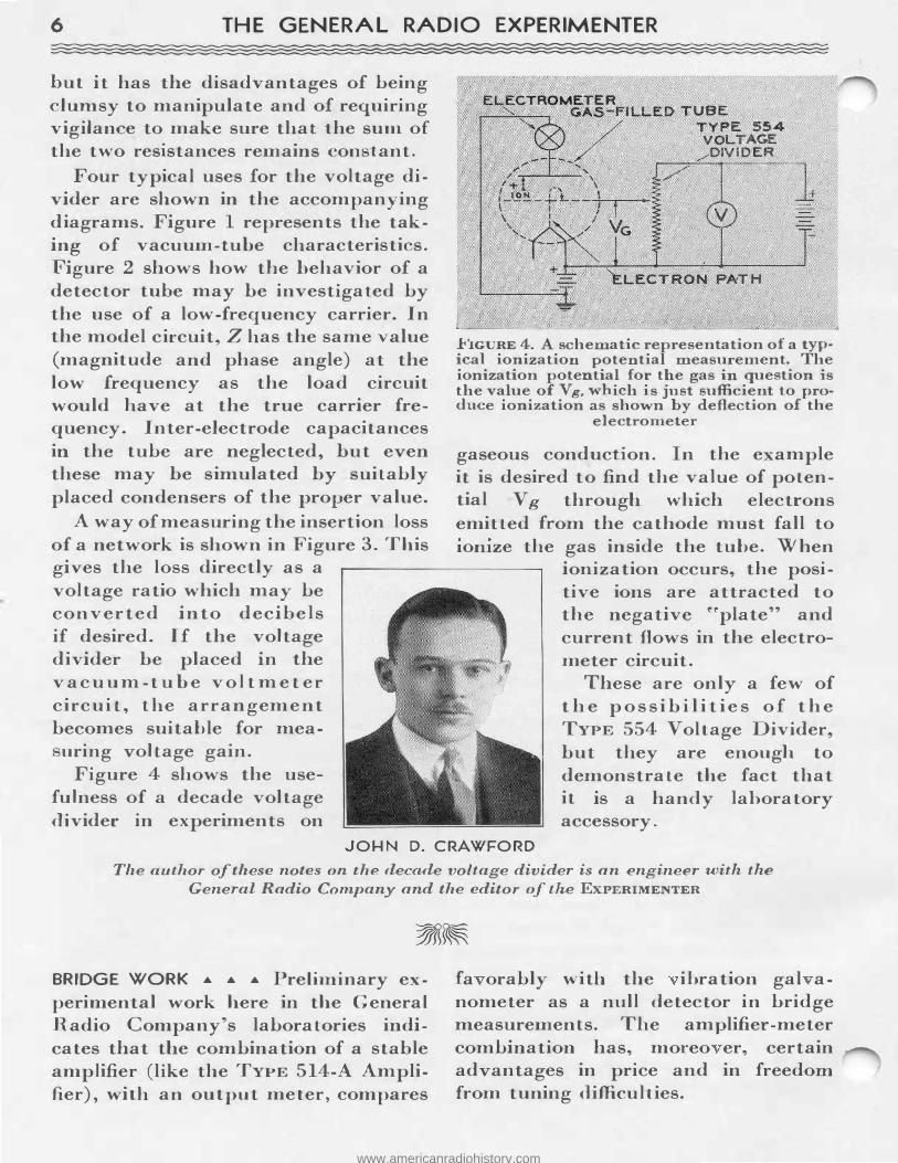
uring voltage gain. Figure 4 shows the use
fulness of a decade voltage divider in experiments on
FIGURE 4. A schematic representation of a typ· ical ionization potential measurement. The ionization potential for the gas in question is the value of V g, which i s just sufficient to produce ionization as shown by deflection of the
electro meter
gaseous conduction. In the example it is desired to find the value of potential V g through which electrons emitted from the cathode must fall to 1omze the gas inside the tube. When
ionization occurs, the positive ions are attracted to the negative ��plate'' and current flows in the electrometer circuit.
These are only a few of t h e p o s s ib i l i t i e s o f t h e TYPE 554 Voltage Divider, but they are enough to demonstrate the fact that it is a handy laboratory accessory.
JOHN D. CRAWFORD
The author of these notes on the decade voltage divider is an engineer with the General Radio Company and the editor of tlie ExPERIMENTER
BRIDGE WORK • • • Preliminary experimental work here in the General Radio Company's laboratories indicates that the combination of a stable amplifier (like the TYPE 514-A Amplifier), with an output meter, compares
fa orably with the ibration gal anometer as a null detector in bridge measurements. The amplifier-meter combination has, moreo er, certain advantages in price and in freedom from tuning difficulties.
www.americanradiohistory.com
JULY, 1931-VOL. VI-No. 2 7
JUDGING METERS • • • Output meters and other meters having multiplier hould be so de igned that: t:hey have a pra tical y onstant: percentage ac ura y. This can be evaluated ' hen judging the suitability of su h a multirange meter by plotting the full-scale value for the different mult iplier settings on logarithmic paper. The poi nt obtained should be appro im.ately equally spaced. The new General Radio TYPE 483 Output Meters close! approximate this ideal.
SIMPLE TUBE TEST • • • A tube :rnanuf acturer has suggested a new use for the General Radio TYPE 404 Test
Signal Generator. Arguing that the only interesting fact about a tube i whether it will or will not function normally in a set, the suggestion i made - why not try it in a set? Of cou r such a te t is not conclusive if t h tube is just stuck i n the set and the set tuned to a broadcast station and a listening test applied. If., however, the rec iver checked for input r quired to give normal output, the tube performance is very accurately check d, and noi e may he observed at the same time. The tube m.ay he checked in its normal position in the r ceiver, and the receiver takes care of the supply of proper voltages.
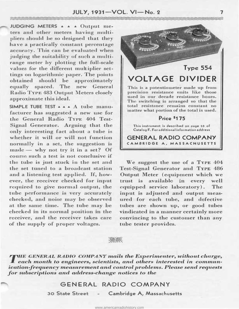
Type 554
VOLT AGE DIVIDER Thi i a potentiometer made up from precision resistance units like those u ed in our decade resistance ho es. Th switching i arranged so that the total resi tance remains constant no
atter what portion of the total is used.
Price s175
This instrument is described on page 25 of
Catalog F. For additional information address
GENERAL RADIO COMPANY CAMBRIDGE A, MASSACHUSETTS
We sugg st the use of a TYPE 404 Test-Signal Generator and TYPE 486 Output Meter (equipment which we trust is availabl n every well
quipped service laboratory). The input is adjusted and output measured for each tube, and d fective tubes are shown up, or good tubes vindicated in a manner certainly more convincing to the customer than any tube tester provides.
TIHE GENERAL RADIO COMPAN mails the Experimenter, without charge, each month to engineers, scientists, and others interested in commun
ication-frequency measurement and control probleTUS. Please send reque ·t;s for ubscriptions and address-change notices to the
GENE RAL RADIO COMPANY 30 State Street Cambridge A, Massachusetts
www.americanradiohistory.com
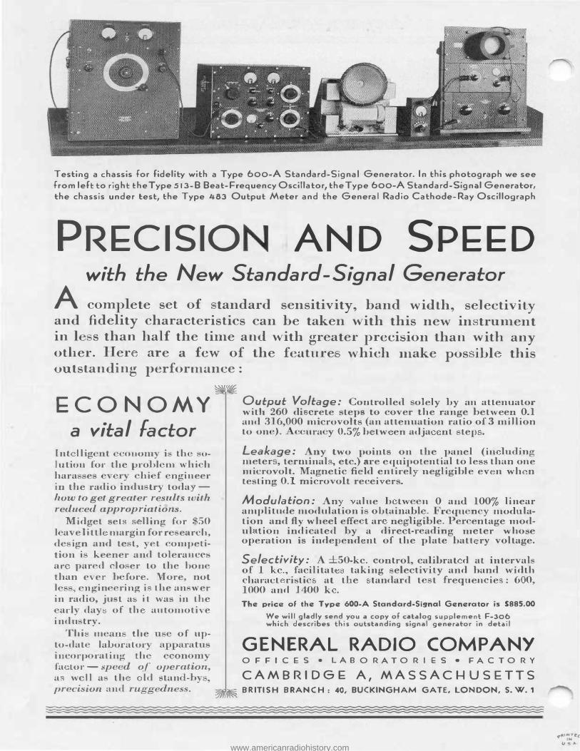
T esl:ing a chassis for fidelity with a Type 600-A Standard-Signal Generator. In this photograph we see from left: l:o right: t:he Type 513-8 Beat-Frequency Oscillator, the Type 600-A Standard-Signal Generator, t:he chassis under l:est, t:he Type 483 Output Meter and l:he General Radio Cathode-Ray Oscillograph
PRECISIO AND SPEED with the New Standard-Signal Generator
A complete set of tandard sensitivity, band width, selectivity and fidelity characteristics can be taken with this new in trument in I s than half the time and with greater precision than with any other. Her are a few of the feature which make pos ibl this o tstanding performance :
�� ECONOMY
a vital factor Int l lig ·onom i - th "' ·o
l ution for the probl m ' bi h hara e r hi f ngineer in the radio indu try toda -
how to get greater results with reduced appropriations.
Midget set lling for . 50 1 avelittl margin for r earch, d ign and te t, t ompetition i keener and tole rances at· par d lo er Lo the hon than ever b fore. More, not L , ngin ring i the an ' er in radio, ju t a it was in the
ad day of tl1 automotive indu try.
Thi m an' the of up-to-dat laboralor incorp rating th fa Lor - peed of operation, a we l l a th kl stan 1-b precision and ruo-gednes ..
Output Voltage: Controlled solely by an attenuator with 260 di crete steps to cover the range between 0.1 and 3 6,000 microvolts (an attenuation ratio of 3 million to on ). · ·ura ·y 0.5% b Lw en adja nt te1 .
Leakage: Any two points on the panel (in ludin.-r meter , terminal , etc.) a e quipotenlial to less than one microvolt. Magnetic fi ld entirel negligible ev n w h n testing 0. microvolt recei ers.
M adulation: An alue h Lw n 0 and 100% linear amplitude modulation i o]Jtainabl . i r qu n y modulation and fly wheel effe tar negligible. Per entage modul tion indicated by a direct-1· a ing meter whose operation is inde1 end nt of the plate batt ry voltage.
Selectivity: A ±SO-kc. control, calihrat d at interval of 1 kc., facilita t taking electi ity and band width charact ristic at the tanda d t t frequencie : 6 0, 1000 and 1 400 k .
The pric:e of the Type 600-A Standard-Signal Generator is $885.00
We will gladly send you a copy of cat:alog supplement: F-306 which describes this outstanding signal generator in detail
GENERAL RADIO COMPANY OFFICES • LABORATORIES • FACTORY
CAMBRIDGE: A, MASSACHUSETTS �� BRITISH BRANCH: 40, BUCKINGHAM GATE, LONDON, S. W. 1
'('ftlNTEc_ IN
us,,._ www.americanradiohistory.com