The F.W. Webb Company - ESF | SUNY ESF
42
10/31/2019 1 F.W. Webb Company Insert subtitle here Steam Fundamentals and Best Practices The F.W. Webb Company Thursday, October 31, 2019 1 2
Transcript of The F.W. Webb Company - ESF | SUNY ESF

10/31/2019
1
F.W. Webb CompanyInsert subtitle here
Steam Fundamentals and Best Practices
The F.W. Webb Company
Thursday, October 31, 2019
1
2

10/31/2019
2
Steam Generation
• Steam is a safe and very efficient heat transfer medium
• Easy to control due to pressure / temperature relationship
• Gives up heat at a constant temperature
• Easily distributed based on pressure drop – i.e. no circulation pumps needed
Why Do We Use Steam?
3
4

10/31/2019
3
Steam & Condensate
STEAM is the gas phase of water. It is produced when water is heated to its boiling point and enough heat energy is absorbed to change phase from a liquid to gas.
CONDENSATE is the hot water near boiling point that is formed as steam releases its heat energy. This can be as a result of minimal heat losses as steam is being delivered, or “purposely” condensing steam at point of heating, producing large amounts of condensate.
Regardless, a steam system is a balance of the gas (steam) and hot liquid (condensate) form of water.
Steam Terminology
PSIG – Basic unit of measurement for pressure –pounds (force) per square inch.
Lb/hr – Basic unit of measurement of steam flow rate –
pounds (mass) per hour.
BTU – Basic unit of measurement for all types of heat energy.
Heat energy required to raise
one pound of water one degree Fahrenheit
Sensible Heat – Heat energy that raises the temperature of water between its
freezing and boiling points.
Latent Heat – Heat energy that changes water from liquid to gas (steam) and
is used for heat transfer. This energy is typically 3 – 5x greater than the
Sensible Heat energy available in water.
Latent Heat is released during heating,
and steam condenses back into hot water (condensate).
5
6

10/31/2019
4
British Thermal Unit (BTU)
The basic unit of measurement for all types of heat energy is the British Thermal Unit or BTU. Specifically, it is the amount of heat energy necessary to raise one pound of water one degree Fahrenheit.
Steam Generation
7
8

10/31/2019
5
Phase Change: Water to Steam
1 lb. of Water = 15.3 oz(70F @ 0 PSIG)
Volume of Water = 0.016 ft3
Volume of Steam = 26.8 ft3
Steam occupies 1,675 times the amount of space than water.3 ft.
3 ft.
3 ft.
32 0F 3 3 0F 21 2 0F 2 1 2 0F 3 38 0F
0 B T U 1 B T U 1 18 9 B T U1 15 0 B T U1 80 B T U
G A U G EP R E S S U R E
P S IG
T E M PO F
H E A T IN B T U /L B S P E C IF ICV O L U M E
C U . F T /L BS E N S IB L E L A T E N T T O T A L
0 32 0 0 0 0 .016
0 33 1 0 1 0 .016
0 212 180 0 180 0 .017
0 212 180 9 70 1150 26 .8
10 0 338 309 8 80 1189 3 .89
10 0 P S IG
Steam Generation
9
10

10/31/2019
6
0
200
340
220
240
260
280
300
320
1510 25 50 100
PRESSURE
TE
MP
ER
AT
UR
E
STEAM
CONDENSATE
1,164 BTUs/lb
946 Latent BTUs218 Sensible BTUs
Saturated Steam Table
Heat Energy Available in1 Pound of Condensate
Heat Energy Available in1 Pound of Steam
Amount of Space Occupied by 1
Pound of Steam
11
12

10/31/2019
7
PRESSURE
TE
MP
ER
AT
UR
E
Pressure / Temp / Volume
• Flow occurs due to pressure drop –always from a higher pressure source to a lower pressure source.
In general, more pressure drop allows more flow.
• Heat transfer occurs from a higher heat source to a lower one
ThermodynamicsBASIC CONCEPTS
13
14

10/31/2019
8
Overview of Industrial Steam Loop
Typical Steam System Components
Steam Traps
Remove condensate and air, hold back (“trap”) steam
Regulators & Control Valves
Valves used for temperature control or to reduce the steam pressure
Condensate Return PumpsElectric or Mechanical, used to pump condensate back to the boiler when it does not have sufficient pressure
15
16

10/31/2019
9
Steam DistributionSteam Supply Piping
• Steam can travel in pipes at velocities exceeding 90 mph
• Speed allows heat energy to be delivered quickly, especially compared to water or oil heating systems
• Pressure and pipe size determine how fast steam will travel
How Fast Does Steam Travel?
17
18

10/31/2019
10
Greater Cost
Greater Heat Loss
Greater Volume of Condensate Formed
Lower Pressure to Steam Users
Not Enough Volume of Steam
Water Hammer and Erosion
Steam Header Sizing
Steam Velocity
Velocity of Steam Flow is determined by the Size of the Outlet Nozzle Size on a Boiler.
Proper Steam Header Sizing…1. Maximum Steam Load
Required.2. Boiler Design Pressure3. Velocity
• Process Heating• Superheated Steam• Sterilization
19
20
10/31/2019
11
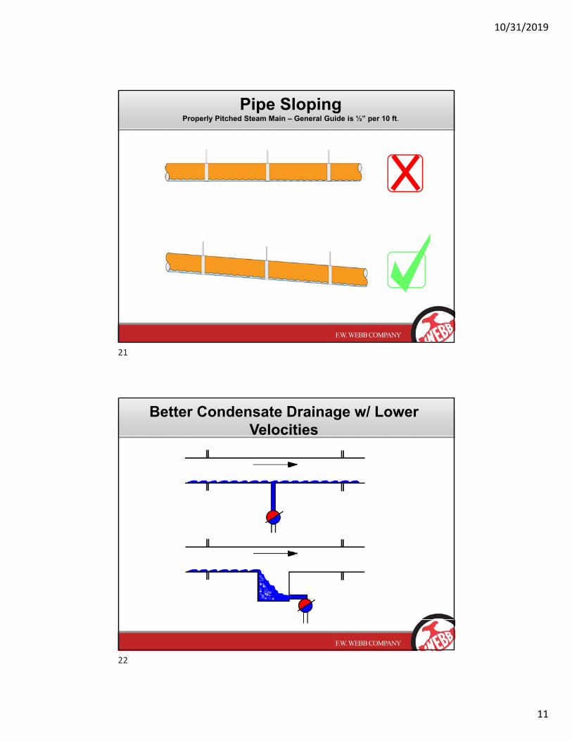
Pipe SlopingProperly Pitched Steam Main – General Guide is ½” per 10 ft.
Better Condensate Drainage w/ Lower Velocities
21
22

10/31/2019
12
Drip Leg Diameter Too Small
Drip Leg Diameter Correctly Sized
Properly Sizing Drip Legs & Steam Traps
1. Pipe SizeSame Size – Up to 6” ½ the Size – Above 6” (But, never less than 6”)
Installing Steam Traps
PROPER DRIP LEG LOCATION & SIZING
2. Length of Drip Leg1 ½ times the Diameter of the Distribution LineNever less than 18”
23
24

10/31/2019
13
Properly Spacing Drip Legs & Steam Traps
Drip Traps on Steam Mains Located Every 150 – 300 ft. of Straight Run of Piping
Properly Locating Drip Legs & Steam Traps
25
26
10/31/2019
14
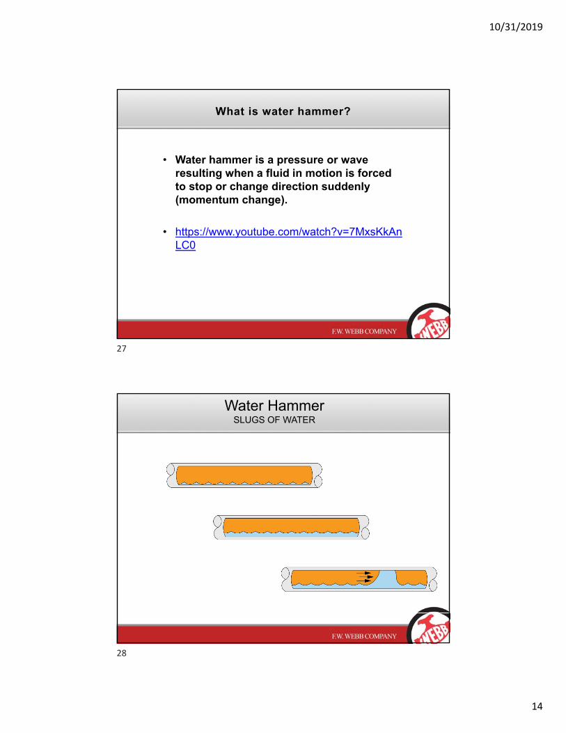
What is water hammer?
• Water hammer is a pressure or wave resulting when a fluid in motion is forced to stop or change direction suddenly (momentum change).
• https://www.youtube.com/watch?v=7MxsKkAnLC0
Water HammerSLUGS OF WATER
27
28

10/31/2019
15
The Danger Of Water HammerPERSONNEL SAFETY!
The Danger Of Water HammerWHAT ABOUT SYSTEM COMPONENTS?
29
30
10/31/2019
16
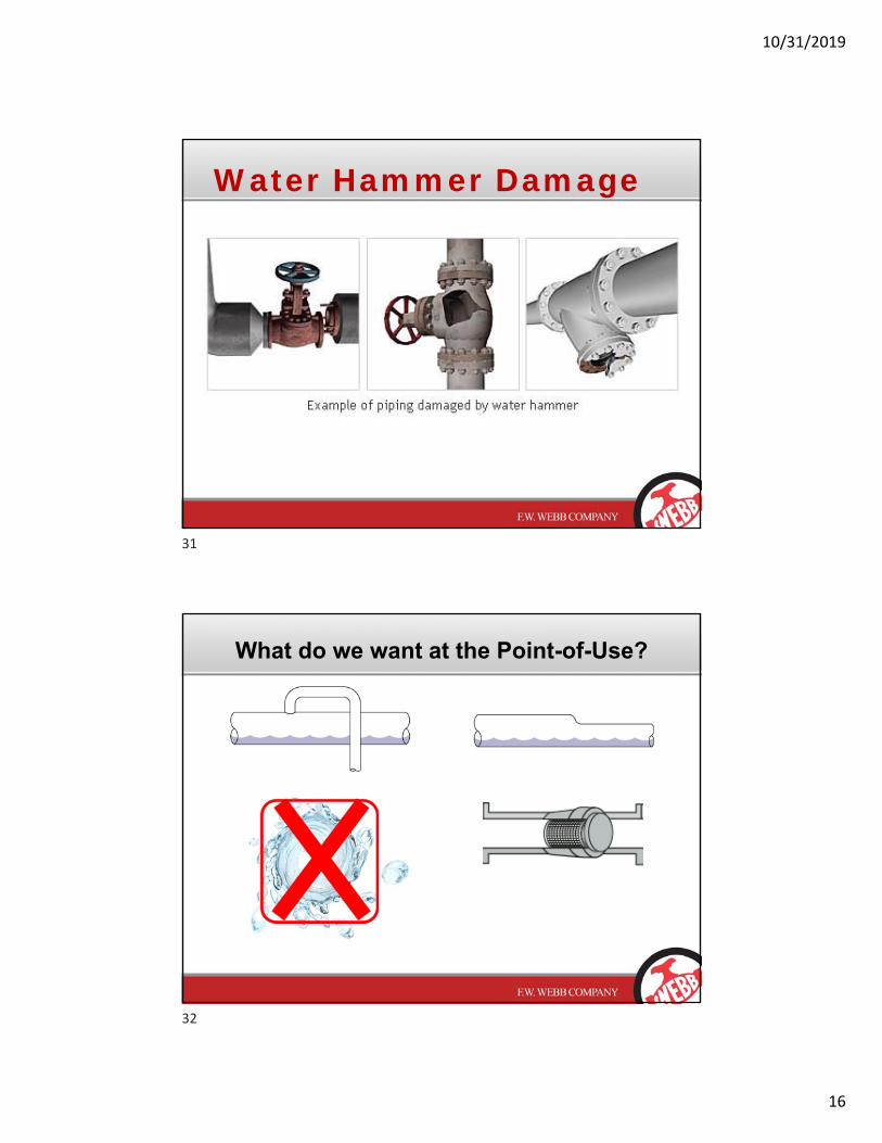
Water Hammer Damage
What do we want at the Point-of-Use?
31
32

10/31/2019
17
Air & Non-Condensable Gases
1. Temperature Reduction - Air is an insulator!• It cannot hold the temperature or latent heat of steam.• 25 times more resistant to heat transfer than water.
2. Carbonic Acid• Air is absorbed into the condensate reducing the pH.• Builds on the inside of the pipe reducing the Inner Diameter.
Air is an Insulator
• Air does not hold the temperature or latent heat of steam.
• 25 times more resistant to heat transfer than water.
33
34

10/31/2019
18
0
200
340
220
240
260
280
300
320
1510 25 50 100
PRESSURE
TE
MP
ER
AT
UR
E
STEAM
CONDENSATE
1,164 BTUs/lb
946 Latent BTUs218 Sensible BTUs
Steam Conditioning Station
Steam Supply
• 771 Btu/lb
• 83% Dryness Fraction
**Double Warranty**On Downstream Controls
Particulate RemovalRemove dirt/rust. Steam Discharge
• 891 Btu/lb
• 96% Dryness Fractio
Entrained Moisture RemovalReduce wear & tear on downstream equipment.
Remove Air/NCsReduces Heat Transfer
Flow Rate
35
36

10/31/2019
19
Condensate Recovery
Now That We’ve Made Steam
What Do We Do With It
37
38
10/31/2019
20
Since Steam is used to Transfer Heat Energy From One Location
to Another . . .
It only makes sense that we take the heat energy back out and
use it to do work.
39
40
10/31/2019
21
When are we done with the steam?
And, what do we do?
Remember:Remember:
The Latent Heat added at the boiler is what we have available to do work in our equipment
BUT . . .
When we remove Latent Heat we create Condensate
42
41
42

10/31/2019
22
What is a Steam Trap?
An automatic valve…1. Stops the flow of steam allowing for complete heat
transfer.
2. Discharge Condensate & Air as required.
3 Types of Steam Traps1. Mechanical or Density
2. Thermostatic or Temperature Controlled
3. Thermodynamic or Velocity Controlled
What makes up a Steam Trap
• A Steam Trap has an orifice
• An orifice alone is not a steam trap
– If flow changes, orifice is not correct
– If pressure drop changes, orifice is not correct
– The orifice must change size as conditions change Orifice
Inlet Connection
Outlet Connection
Body
43
44

10/31/2019
23
What makes up a Steam Trap
• A Steam Trap should have a valve
– A valve may be fully opened and fully closed or modulated to vary the size of the orifice as conditions change
Orifice
Inlet Connection
Outlet Connection
Body
Valve
What makes up a Steam Trap
• A Steam Trap should have an Operator
– An operator senses when to move the valve and supplies the power to move the valve
– Traps are different in the types of valve and the types of operator they use
Inlet Connection
Outlet Connection
Body
Valve
Orifice
Operator
45
46

10/31/2019
24
STEAM TRAP FUNCTION
• PREVENTION OF STEAM LOSS
• CONDENSATE REMOVAL
• AIR AND NON CONDENSIBLE GAS REMOVAL
• REACT TO CHANGES IN LOAD
Most Common Steam Traps
1. Float & Thermostatic Traps• Excellent for main headers.• Ideal for process/batch process.• Best air removal option.
2. Inverted Bucket Traps• Good for continuous systems.• Poor air removal.• Prime required.
3. Thermodynamic Traps• Ideal for Medium & High Pressure
Drip Legs
47
48

10/31/2019
25
Benefits• Simple Construction
• Continuous Discharge
• Fast Response To Changing Loads
• Hot Discharge
• Function Under High Back Pressure
• Energy Efficient
• Excellent Air Venting
Considerations• Relatively Large & Heavy• Floats Can Be Damaged By
Severe Water Hammer• Poor With Superheat• Not Self-Draining – Can
Freeze• Fails Closed When Over
Pressurized• Can Fail Open Or Closed
Float & Thermostatic Steam Traps BENEFITS & CONSIDERATIONS
Benefits• Simple Construction• Rugged• Fast Response To
Changing Loads• Hot Discharge• Function Under High Back
Pressure• Operation Is Generally
Cyclic• Generally Fails Open
Considerations• Poor Air Venting• Poor With Superheat• Not Self-draining – Can
Freeze• Fail Open With Prime Loss• Fails Closed When Over-
Pressurized
Inverted Bucket Steam Traps BENEFITS & CONSIDERATIONS
49
50

10/31/2019
26
Benefits• Simple Construction• Small & Light• Mount In Any Position• Self Draining (Freeze Proof)• Operates Over A Wide
Pressure Range• Energy Efficient• More Subcool Limits Flash
Steam Created
Considerations• Condensate Subcooling
may require additional pipe run
• Bellows can be damaged by Severe Waterhammer
• Bellows offers Limited Superheat Capability
• Bimetal slower reacting
Thermostatic Steam Traps BENEFITS & CONSIDERATIONS
Benefits• Simple Construction• Small & Light• Mounting In Any Position• Operation Easily Checked
(Audible)• Not Damaged By Freezing
Or Water Hammer• Operates Over A Wide
Pressure Range• Gradual Failure – Open
Position
Considerations• Marginal Air Venting• Sensitive To Excess Back
Pressure• Blast Discharge• Noisy Discharge• Marginal Dirt Handling
Thermodynamic Steam Traps BENEFITS & CONSIDERATIONS
51
52
10/31/2019
27
Time For A Break
Applications & Hook Up Drawings
53
54

10/31/2019
28
• Flow occurs due to pressure drop –always from a higher pressure source to a lower pressure source.
In general, more pressure drop allows more flow.
ThermodynamicsBASIC CONCEPTS
System Pressure: Modulating vs. Constant
Pre
ssu
reP
ress
ure
Time
Time
55
56

10/31/2019
29
Main Line Drip or End of Main Hook Up
Warm-Up Load Calculations
57
58

10/31/2019
30
Running Load Calculations
(Feet ) X (5A Run Load X 5C Efficiency)150 X(1.36 X .07) = 17.43 pphr running LoadTrap Load = 17.43 x 3:1SF = 52.29 pphr
Unit Heater Hook Up
59
60

10/31/2019
31
System Pressure: Modulating vs. Constant
Pre
ssu
reP
ress
ure
Time
Time
Shell & Tube Exchanger Hook Up
61
62
10/31/2019
32
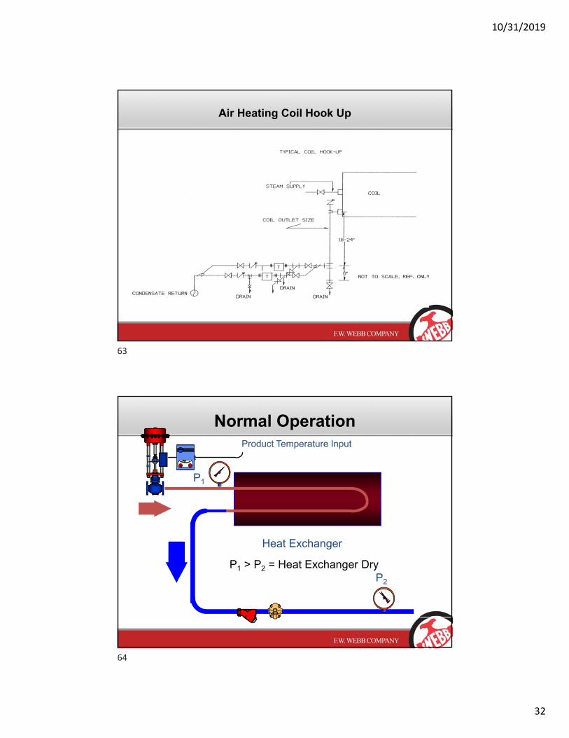
Air Heating Coil Hook Up
Normal Operation
Heat Exchanger
P2
P1
Product Temperature Input
P1 > P2 = Heat Exchanger Dry
63
64

10/31/2019
33
Downstream Lift = System Back Pressure
Heat Exchanger
Stall Condition – No Steam Supply
P2
Product Temperature Input
P1<P2=Heat Exchanger Flooded
P1
65
66

10/31/2019
34
Stall Chart
StallPump Mode
Trap Mode
65% = Stallof LoadPoint
What does a stall chart not take into consideration?
Domestic Hot Water
15 PSIG Steam Supply@ 250F
40F to 140F @ 100 GPM
0 PSIG Back-Pressure@ 212F
(aka Gravity-Drain)
Reasons for System Stall
• Overly conservative fouling factors during HEX design –adds additional surface area
• Back pressure at equipment discharge – elevation or static pressure
• Modulating Control – Steam pressure
• Vacuum
• Process demands- Flow or temp changes
• Oversized equipment – excess surface area
67
68

10/31/2019
35
Effects of System Stall
• Inadequate condensate drainage
• Water hammer (Thermal Shock)
• Frozen coils, damaged tube bundles
• Poor temperature control
• Control valve hunting – control stability
• Reduction in heat transfer capacity
System Stall Solutions
Installation of a vacuum breaker:
Objective:
To relieve a vacuum within equipment allowing for condensate drainage.
Shortcoming:
This practice will only help if the condensate is gravity drain to atmosphere,
Allows undesirable air into the system.
Vacuum breakers often fail due to a poorly chosen location
Loss of valuable flash steam
69
70

10/31/2019
36
Flash Steam Generation
Phase Change: Water to Steam
1 lb. of Water = 15.3 oz(70F @ 0 PSIG)
Volume of Water = 0.016 ft3
Volume of Steam = 26.8 ft3
Steam occupies 1,675 times the amount of space than water.3 ft.
3 ft.
3 ft.
71
72

10/31/2019
37
Flash Capacity Calculation – Page #41
What is Flash Steam?
73
74

10/31/2019
38
Quantify Flash Steam
1000 lb/hr
60 psig 0 psig
Flash Steam
Mass = 100 lb
Spec. Vol. = 26.80 ft3
99.4% of Total Volume
Condensate
Mass = 900 lb
Spec. Vol. = .016 ft3
0.6 % of Total Volume
Steam Trap Energy Losses
• Failed Open or Blowing Traps, average 10 – 11% of your trap population. Traps that have failed in the open position do not allow stream to condense in the exchanging surface. This results in the need for more steam to do the needed work. This results in added fuel oil expenses. These losses are measurable and can be quantified.
• Failed Closed or Cold Plugged Traps, average around 10% of your trap population. Traps that have failed closed, do not allow condensate to be removed from the exchanging surface. This results in poor system efficiencies, corrosion and water hammer. Although we can not measure their effect of fuel oil costs, there is a hidden loss in maintenance and trouble and complaint calls.
75
76

10/31/2019
39
Steam Trap Energy Losses
Modified Napier Formula, can be used to estimate steam loss through a trap blowing to atmosphere. The following is the equation used in calculating the approximate loss:
Modified Napier FormulaSteam loss in lbs./hr = (24.24) * ( Pa) * (D*D)
Where:Pa = Pressure in Absolute ex. Gauge Pressure + 14.7D = Orifice Diameter in Trap in Inches.
Example: Inverted Bucket Trap on main steam drip station on 125-psi steam service 0.75” pipe connection, rated at 125-psi differential. From manufacturers’ literature, this trap has a 0.125” orifice. Using the Modified Napier Calculation, the calculated steam blow through this orifice is as follows:
Steam Loss in lbs. /hr = (24.24) * (Pa) * (D*D) or the following:
Steam Loss in lbs. /hr = (24.24) * (139.7) * (0.125*0.125) or 52.91 lbs. /hr loss
Steam Flow Through Orifices Discharging to AtmosphereORIFICE ORIFICE
DIA DIA STEAM LOSS ,LB/HR, WHEN GAUGE PRESSURE IS:
DECIMAL FRACTION 2 5 10 15 20 25 30 35 40 50 60 75 90 100
0.031 1/32 0.39 0.46 0.58 0.69 0.81 0.92 1.04 1.16 1.27 1.51 1.74 2.09 2.44 2.67
0.0625 1/16 1.58 1.87 2.34 2.81 3.29 3.76 4.23 4.71 5.18 6.13 7.07 8.49 9.91 10.86
0.0781 5/64 2.47 2.91 3.65 4.39 5.13 5.87 6.61 7.35 8.09 9.57 11.04 13.26 15.48 16.96
0.0937 3/32 3.55 4.19 5.26 6.32 7.38 8.45 9.51 10.58 11.64 13.77 15.90 19.09 22.28 24.41
0.109 7/64 4.81 5.67 7.11 8.55 9.99 11.43 12.87 14.31 15.75 18.63 21.51 25.83 30.15 33.03
0.125 1/8 6.33 7.46 9.36 11.25 13.14 15.04 16.93 18.82 20.72 24.51 28.29 33.97 39.66 43.44
0.156 5/32 9.85 11.62 14.57 17.52 20.47 23.42 26.37 29.32 32.27 38.17 44.07 52.91 61.76 67.66
0.1718 11/64 11.95 14.09 17.67 21.25 24.83 28.40 31.98 35.56 39.14 46.29 53.44 64.18 74.91 82.06
0.1875 3/16 14.23 16.79 21.05 25.31 29.57 33.83 38.09 42.35 46.61 55.14 63.66 76.44 89.22 97.75
0.2031 13/64 16.70 19.70 24.70 29.70 34.70 39.70 44.70 49.69 54.69 64.69 74.69 89.69 104.69 114.6
0.2187 7/32 19.36 22.84 28.64 34.43 40.23 46.03 51.82 57.62 63.42 75.01 86.61 104.00 121.39 132.9
0.2343 15/64 22.22 26.21 32.87 39.52 46.17 52.83 59.48 66.14 72.79 86.10 99.40 119.36 139.32 152.6
0.25 1/4 25.30 29.85 37.42 45.00 52.57 60.15 67.72 75.30 82.87 98.02 113.17 135.90 158.62 173.7
0.2812 9/32 32.01 37.76 47.34 56.93 66.51 76.09 85.68 95.26 104.85 124.01 143.18 171.93 200.68 219.8
0.3437 11/32 47.82 56.41 70.73 85.04 99.36 113.68 128.00 142.31 156.63 185.27 213.90 256.85 299.80 328.4
0.375 3/8 56.93 67.15 84.20 101.24 118.28 135.33 152.37 169.41 186.46 220.55 254.63 305.76 356.90 390.9
0.4062 13/32 66.79 78.79 98.79 118.79 138.78 158.78 178.78 198.78 218.78 258.77 298.77 358.76 418.75 458.7
0.4375 7/16 77.48 91.40 114.60
137.80 161.00 184.20 207.39 230.59 253.79 300.19 346.58 416.18 485.78 532.1
0.4687 15/32 88.93 104.90 131.53
158.15 184.78 211.40 238.03 264.65 291.28 344.53 397.78 477.66 557.53 610.7
0.5 1/2 101.20 119.38 149.68
179.98 210.28 240.58 270.88 301.18 331.48 392.08 452.68 543.58 634.48 695.0
77
78
10/31/2019
40
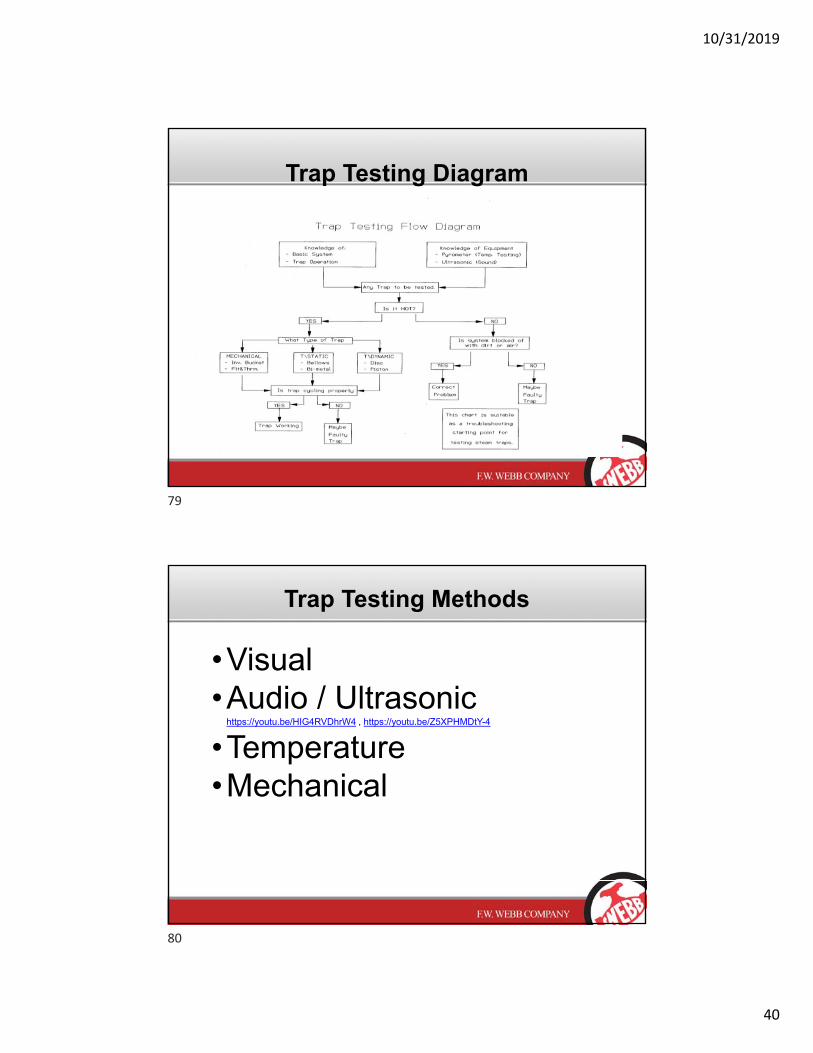
Trap Testing Diagram
Trap Testing Methods
•Visual•Audio / Ultrasonic
https://youtu.be/HIG4RVDhrW4 , https://youtu.be/Z5XPHMDtY-4
•Temperature•Mechanical
79
80

10/31/2019
41
• Steam – Latent Heat
• Proper Piping
• Select the Right Steam Trap Technology
• Steam Quality and Non Condensable Gases
• Reduce Back Pressure after Trap
RECAP OF KEY POINTS
Selection. Expertise. Solutions.
Slides Courtesy of:Armstrong InternationalSpiraxSarcoWatson McDaniel
81
82
10/31/2019
42
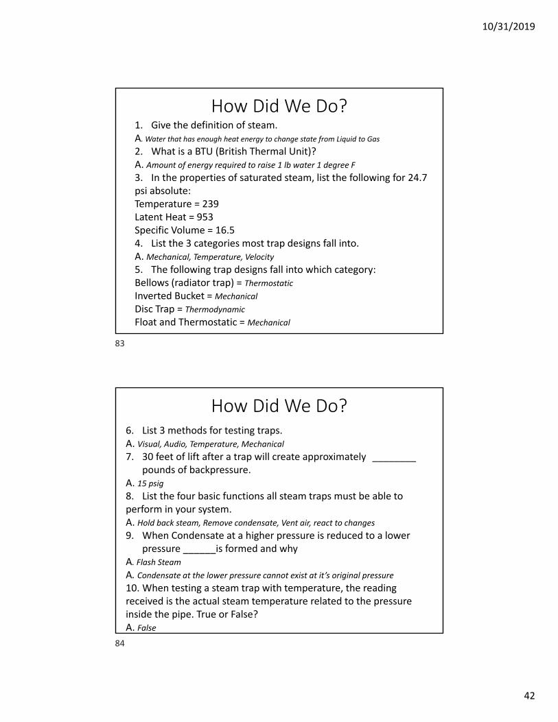
How Did We Do?1. Give the definition of steam.A. Water that has enough heat energy to change state from Liquid to Gas
2. What is a BTU (British Thermal Unit)?A. Amount of energy required to raise 1 lb water 1 degree F
3. In the properties of saturated steam, list the following for 24.7 psi absolute:Temperature = 239Latent Heat = 953Specific Volume = 16.54. List the 3 categories most trap designs fall into.A. Mechanical, Temperature, Velocity
5. The following trap designs fall into which category:Bellows (radiator trap) = Thermostatic
Inverted Bucket = Mechanical
Disc Trap = Thermodynamic
Float and Thermostatic = Mechanical
How Did We Do?6. List 3 methods for testing traps.A. Visual, Audio, Temperature, Mechanical
7. 30 feet of lift after a trap will create approximately ________ pounds of backpressure.
A. 15 psig8. List the four basic functions all steam traps must be able to perform in your system.A. Hold back steam, Remove condensate, Vent air, react to changes
9. When Condensate at a higher pressure is reduced to a lower pressure ______is formed and why
A. Flash SteamA. Condensate at the lower pressure cannot exist at it’s original pressure 10. When testing a steam trap with temperature, the reading received is the actual steam temperature related to the pressure inside the pipe. True or False?A. False
83
84