The Fundamentals of SONET - Mauimauigateway.com/~surfer/library/fundamentals-of-SONET.pdf ·...
31
1 Fundamentals of SONET Overview When fiber optical cables were initially deployed as a medium for high-speed digital transport, the lack of standards led to widespread deployment of proprietary optical interfaces. This meant that fiber optic transmis- sion equipment from one manufacturer could not inter- face with equipment from any of the other manufactur- ers. Service providers were required to select a single vendor for deployment throughout the network and then were locked in to the network control and monitoring capabilities of that manufacturer. Although this technol- ogy satisfied the bandwidth needs of the network for several years, it was evident that this arrangement could not support the future needs of the industry because of the limited interconnection capabilities. In 1985, Bellcore proposed the idea of an optical carrier-to-carrier interface that would allow the inter- connection of different manufacturers’ optical equip- ment. This was based on a hierarchy of digital rates, all formed by the interleaving of a basic rate signal. The idea of a Synchronous Optical NETwork (SONET) attracted the interest of carriers, Regional Bell Operating Companies (RBOCs), and manufacturers alike and quickly gained momentum. Interest in SONET by CCITT (now International Telecommunication Union – ITU-T) expanded its scope from a domestic to an international standard, and by 1988 the ANSI committee had suc- cessfully integrated changes requested by the ITU-T, and were well on their way toward the issuance of the new standard. Today, the SONET standard is contained in the ANSI specification T1.105 Digital Hierarchy – Optical Interface Rates & Formats Specifications (SONET), and technical recommendations are found in Bellcore GR-253-CORE Synchronous Optical Network (SONET) Transport Systems: Common Generic Crite- ria. The SONET specifications define optical carrier (OC) interfaces and their electrical equivalents to allow transmission of lower-rate signals at a common synchronous rate. One of the benefits of the SONET signal, as with any standard, is that it allows multiple vendors to provide compatible transmission equipment in the same span. SONET also allows for dynamic drop and insert capabilities on the payload without the delay and additional hardware associated with demultiplexing and remultiplexing the higher rate signal. Since the overhead is relatively independent of the payload, SONET is able to integrate new services, such as Asyn- chronous Transfer Mode (ATM) and Fiber Distributed Data Interface (FDDI), in addition to existing DS3 and DS1 services. Another major advantage of SONET is that the operations, administration, maintenance, and provi- sioning (OAM&P) capabilities are built directly into the signal overhead to allow maintenance of the network from one central location. SONET Multiplexing SONET multiplexing combines low-speed digital signals such as DS1, DS1C, E1, DS2, and DS3 with required overhead to form a building block called Synchronous Transport Signal Level One (STS-1). Figure 1 on the next page shows the STS-1 frame, which is organized as 9 rows by 90 columns of bytes. It is transmitted row first, with the most significant bit (MSB) of each byte transmitted first. The Fundamentals of SONET
Transcript of The Fundamentals of SONET - Mauimauigateway.com/~surfer/library/fundamentals-of-SONET.pdf ·...
1
Fun
dam
en
tals o
f SO
NET
Overview
When fiber optical cables were initially deployed
as a medium for high-speed digital transport, the lack of
standards led to widespread deployment of proprietary
optical interfaces. This meant that fiber optic transmis-
sion equipment from one manufacturer could not inter-
face with equipment from any of the other manufactur-
ers. Service providers were required to select a single
vendor for deployment throughout the network and then
were locked in to the network control and monitoring
capabilities of that manufacturer. Although this technol-
ogy satisfied the bandwidth needs of the network for
several years, it was evident that this arrangement could
not support the future needs of the industry because of
the limited interconnection capabilities.
In 1985, Bellcore proposed the idea of an optical
carrier-to-carrier interface that would allow the inter-
connection of different manufacturers’ optical equip-
ment. This was based on a hierarchy of digital rates, all
formed by the interleaving of a basic rate signal. The
idea of a Synchronous Optical NETwork (SONET)
attracted the interest of carriers, Regional Bell Operating
Companies (RBOCs), and manufacturers alike and
quickly gained momentum. Interest in SONET by CCITT
(now International Telecommunication Union – ITU-T)
expanded its scope from a domestic to an international
standard, and by 1988 the ANSI committee had suc-
cessfully integrated changes requested by the ITU-T,
and were well on their way toward the issuance of the
new standard. Today, the SONET standard is contained
in the ANSI specification T1.105 Digital Hierarchy –
Optical Interface Rates & Formats Specifications
(SONET), and technical recommendations are found in
Bellcore GR-253-CORE Synchronous Optical Network
(SONET) Transport Systems: Common Generic Crite-
ria.
The SONET specifications define optical carrier
(OC) interfaces and their electrical equivalents to allow
transmission of lower-rate signals at a common
synchronous rate. One of the benefits of the SONET
signal, as with any standard, is that it allows multiple
vendors to provide compatible transmission equipment
in the same span. SONET also allows for dynamic drop
and insert capabilities on the payload without the delay
and additional hardware associated with demultiplexing
and remultiplexing the higher rate signal. Since the
overhead is relatively independent of the payload,
SONET is able to integrate new services, such as Asyn-
chronous Transfer Mode (ATM) and Fiber Distributed
Data Interface (FDDI), in addition to existing DS3 and
DS1 services. Another major advantage of SONET is that
the operations, administration, maintenance, and provi-
sioning (OAM&P) capabilities are built directly into the
signal overhead to allow maintenance of the network
from one central location.
SONET Multiplexing
SONET multiplexing combines low-speed digital
signals such as DS1, DS1C, E1, DS2, and DS3 with
required overhead to form a building block called
Synchronous Transport Signal Level One (STS-1).
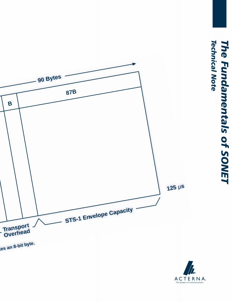
Figure 1 on the next page shows the STS-1 frame,
which is organized as 9 rows by 90 columns of bytes. It
is transmitted row first, with the most significant bit
(MSB) of each byte transmitted first.
The Fundamentals of SONET

2
Fun
dam
en
tals
of
SO
NET
Figure 1
STS-1 frame.
A generic formula calculates the bit rate of a
framed digital signal:
bit rate = frame rate x frame capacity
In order for SONET to easily integrate existing
digital services into its hierarchy, it was defined to
operate at the basic rate of 8 kHz or 125 microseconds
per frame, so the frame rate is 8,000 frames per second.
The frame capacity of a signal is the number of
bits contained within a single frame. Figure 1 shows:
frame capacity = 90 bytes/row x 9 rows/frame x
8 bits/byte = 6,480 bits/frame
Now the bit rate of the STS-1 signal is calculated
as follows:
bit rate = 8,000 frames/second x
6,480 bits/frame = 51.840 Mbps
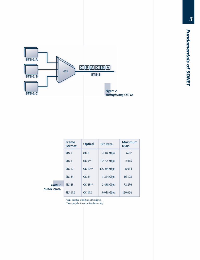
Higher-rate signals are formed by combining
multiples of the STS-1 block by interleaving a byte
from each STS-1 to form an STS-3, as shown in Figure
2. The basic frame rate remains 8,000 frames per
second, but the capacity is tripled to result in a bit rate of
155.52 Mbps. The STS-3 may then be converted to an
optical signal (OC-3) for transport, or further multi-
plexed with three additional STS-3s to form an STS-12
signal, and so on. Table 1 defines common SONET
optical rates, their equivalent electrical rates, and the
maximum number of DS0 voice channels which can be
carried at that rate.
90 Bytes
9Rows
B B B 87B
125 µs
TransportOverhead
STS-1 Envelope Capacity
B denotes an 8-bit byte.
3
Fun
dam
en
tals o
f SO
NET
Table 1
SONET rates.
FrameFormat
Optical Bit RateMaximumDS0s
STS-1 OC-1 51.84 Mbps 672*
STS-3 OC-3** 155.52 Mbps 2,016
STS-12 OC-12** 622.08 Mbps 8,064
STS-24 OC-24 1.244 Gbps 16,128
STS-48 OC-48** 2.488 Gbps 32,256
STS-192 OC-192 9.953 Gbps 129,024
*Same number of DS0s as a DS3 signal.
**Most popular transport interfaces today.
3:1
STS-1 A
STS-3STS-1 B
STS-1 C
C B A C B A
Figure 2
Multiplexing STS-1s.

4
Fun
dam
en
tals
of
SO
NET
SONET Frame
Figure 3 shows the STS-1 frame divided into two
parts to physically segregate the layers, where each
square represents an 8-bit byte. The first three columns
comprise the transport overhead (TOH), while the re-
mainder is called the synchronous payload envelope
(SPE). The TOH dedicates three rows for the section
overhead (SOH) and six rows for the line overhead
(LOH). The SPE contains one column for the path over-
head (POH), leaving the remaining 86 columns for pay-
load data (49.536 Mbps). Appendix A on page 26
is included as a reference to describe each of the bytes
in Figure 3.
Figure 3
SONET overhead structure.
SONET Signal Hierarchy
The SONET signal is layered to divide respon-
sibility for transporting the payload through the network.
Each network element (NE) is responsible for interpret-
ing and generating its overhead layer, and for commu-
nicating control and status information to the same layer
LineOverhead
Transport Overhead
Framing
A1
Framing
A2
BIP-8
B1
Orderwire
E1
User
F1
Data Com
D1
Data Com
D2
Data Com
D3
Pointer
H1
Pointer
H2
Pointer Action
H3
BIP-8
B2
APS
K1
APS
K2
Data Com
D4
Data Com
D5
Data Com
D6
FEBE
M0
Orderwire
E2
Data Com
D7
Data Com
D8
Data Com
D9
Data Com
D10
Data Com
D11
Data Com
D12
Trace
J1
BIP-8
B3
Signal Label
C2
Path Status
G1
User Channel
F2
Multiframe
H4
TandemConnect
Z5
Growth
Z3
Growth
Z4
SectionOverhead
Synchronous Payload Envelope
3 Bytes 87 Bytes
9Rows
Trace
J0
Synch
S1
5
Fun
dam
en
tals o
f SO
NET
within the identical piece of equipment. Since each layer
is terminated and regenerated at the appropriate nodes,
the performance monitoring data at each NE will help
to sectionalize a problem.
For example, if traffic is traveling west to east in
Figure 4, and section errors are detected at Site 4, a
problem will be somewhere between Site 3 and Site 4.
The observed problem cannot be west of Site 3, since
all section results are recalculated at every point in the
network. If line errors are found at Site 4, a problem
exists between Site 2 and Site 4, since line results are
recalculated only at major nodes in the network, such
as the ADM at Site 2. Finally, if path errors are detected
at Site 4, then a problem exists anywhere between
Site 1 and Site 4.
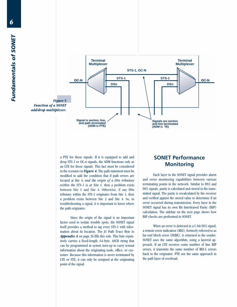
The ADM at Site 2 adds a twist to the path errors
example, due to its flexible functionality as shown in
Figure 5 on the next page. An ADM functions as a PTE
when the signals being dropped and added are tributar-
ies of the SONET signal. If the ADM has been equipped to
add and drop DS3 or DS1 signals, the ADM functions as
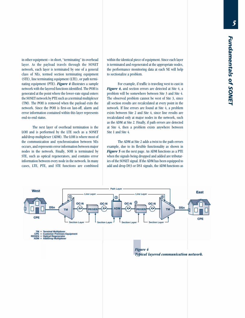
Figure 4
Typical layered communication network.
in other equipment – in short, “terminating” its overhead
layer. As the payload travels through the SONET
network, each layer is terminated by one of a general
class of NEs, termed section terminating equipment
(STE), line terminating equipment (LTE), or path termi-
nating equipment (PTE). Figure 4 illustrates a sample
network with the layered functions identified. The POH is
generated at the point where the lower-rate signal enters
the SONET network by PTE such as a terminal multiplexer
(TM). The POH is removed when the payload exits the
network. Since the POH is first-on last-off, alarm and
error information contained within this layer represents
end-to-end status.
The next layer of overhead termination is the
LOH and is performed by the LTE such as a SONET
add/drop multiplexer (ADM). The LOH is where most of
the communication and synchronization between NEs
occurs, and represents error information between major
nodes in the network. Finally, SOH is terminated by
STE, such as optical regenerators, and contains error
information between every node in the network. In many
cases, LTE, PTE, and STE functions are combined
CPE
East
DSnADM
CPE
OC-N
West
Section Layer
DSn
TMCPE
REGENADM
====
Terminal MultiplexerCustomer Premises EquipmentOptical RegeneratorAdd/Drop Multiplexer
TM
OC-N
REGEN
Line Layer
Section Layer
OC-N OC-N
REGEN
Section Layer Section Layer
TM
Line Layer1 4
3
2
Path Layer
6
Fun
dam
en
tals
of
SO
NET
a PTE for those signals. If it is equipped to add and
drop STS-1 or OC-n signals, the ADM functions only as
an LTE for those signals. This fact must be considered
in the scenario in Figure 4. The path statement must be
modified to add the condition that if path errors are
located at Site 4, and the origin of a DSn tributary
within the STS-1 is at Site 1, then a problem exists
between Site 1 and Site 4. Otherwise, if any DSn
tributary within the STS-1 originates from Site 2, then
a problem exists between Site 2 and Site 4. So, in
troubleshooting a signal, it is important to know where
the path originates.
Since the origin of the signal is an important
factor used to isolate trouble spots, the SONET signal
itself provides a method to tag every STS-1 with infor-
mation about its location. The J1 Path Trace Byte in
Appendix A on page 26 fills this role. This byte repeti-
tively carries a fixed-length, 64-byte, ASCII string that
can be programmed at system turn-up to carry textual
information about the originating node, office, or cus-
tomer. Because this information is never terminated by
LTE or STE, it can only be assigned at the originating
point of the signal.
SONET PerformanceMonitoring
Each layer in the SONET signal provides alarm
and error monitoring capabilities between various
terminating points in the network. Similar to DS3 and
DS1 signals, parity is calculated and stored in the trans-
mitted signal. The parity is recalculated by the receiver
and verified against the stored value to determine if an
error occurred during transmission. Every layer in the
SONET signal has its own Bit Interleaved Parity (BIP)
calculation. The sidebar on the next page shows how
BIP checks are performed in SONET.
When an error is detected in a C-bit DS3 signal,
a remote error indication (REI), formerly referred to as
far-end block error (FEBE), is returned to the sender.
SONET uses the same algorithm, using a layered ap-
proach. If an LTE receives some number of line BIP
errors, it transmits the same number of REI-L errors
back to the originator. PTE use the same approach in
the path layer of overhead.
Signal is section, line,and path terminated
(ADM is PTE)
Signals are sectionand line terminated(ADM is TE)
STS-1, OC-N
STS-1
DSnOC-N
STS-1
DSnOC-N
TerminalMultiplexer
TerminalMultiplexer
Figure 5
Function of a SONET
add/drop multiplexer.
7
Fun
dam
en
tals o
f SO
NET
The SONET signal also contains AIS and Yellow
alarms, like DS3 and DS1, except a SONET Yellow alarm
is called a remote defect indication (RDI), and is also
layered like all of the other SONET results. The term
RDI replaces the former names FERF (far-end receive
failure) and RAI (remote alarm indication) from previ-
ous versions of the SONET specification.
SONET Timing Compensation
The SONET signal was designed to be timing-
tolerant to support asynchronously timed, lower-rate
signals and slight timing differences between synchro-
nously timed NEs. There are two mechanisms which
allow for robust timing compensation: variable bit
stuffing of the lower-rate signal, and a technique called
“pointer adjustments” between synchronous elements
in the SONET network.
Pointer Adjustments
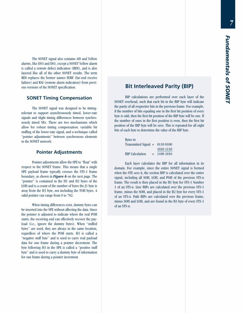
Pointer adjustments allow the SPE to “float” with
respect to the SONET frame. This means that a single
SPE payload frame typically crosses the STS-1 frame
boundary, as shown in Figure 6 on the next page. The
“pointer” is contained in the H1 and H2 bytes of the
LOH and is a count of the number of bytes the J1 byte is
away from the H3 byte, not including the TOH bytes. A
valid pointer can range from 0 to 782.
When timing differences exist, dummy bytes can
be inserted into the SPE without affecting the data. Since
the pointer is adjusted to indicate where the real POH
starts, the receiving end can effectively recover the pay-
load (i.e., ignore the dummy bytes). When “stuffed
bytes” are used, they are always in the same location,
regardless of where the POH starts. H3 is called a
“negative stuff byte” and is used to carry real payload
data for one frame during a pointer decrement. The
byte following H3 in the SPE is called a “positive stuff
byte” and is used to carry a dummy byte of information
for one frame during a pointer increment.
Bit Interleaved Parity (BIP)
BIP calculations are performed over each layer of the
SONET overhead, such that each bit in the BIP byte will indicate
the parity of all respective bits in the previous frame. For example,
if the number of bits equaling one in the first bit position of every
byte is odd, then the first bit position of the BIP byte will be one. If
the number of ones in the first position is even, then the first bit
position of the BIP byte will be zero. This is repeated for all eight
bits of each byte to determine the value of the BIP byte.
Bytes in
Transmitted Signal = 0110 0100
1010 1110
BIP Calculation = 1100 1010
Each layer calculates the BIP for all information in its
domain. For example, since the entire SONET signal is formed
when the STE sees it, the section BIP is calculated over the entire
signal, including all SOH, LOH, and POH of the previous STS-n
frame. The result is then placed in the B1 byte for STS-1 Number
1 of an STS-n. Line BIPs are calculated over the previous STS-1
frame, minus the SOH, and placed in the B2 byte for every STS-1
of an STS-n. Path BIPs are calculated over the previous frame,
minus SOH and LOH, and are found in the B3 byte of every STS-1
of an STS-n.
8
Fun
dam
en
tals
of
SO
NET
H1 H2 H3
3 Bytes 87 Bytes
H1 H2 H3
9Rows
9Rows
STS-1POH
J1
STS-1 SPE
Frame N
125 µs
Frame N + 1
250 µs
Figure 6
Pointer bytes
designating the
start of the SPE
path overhead.
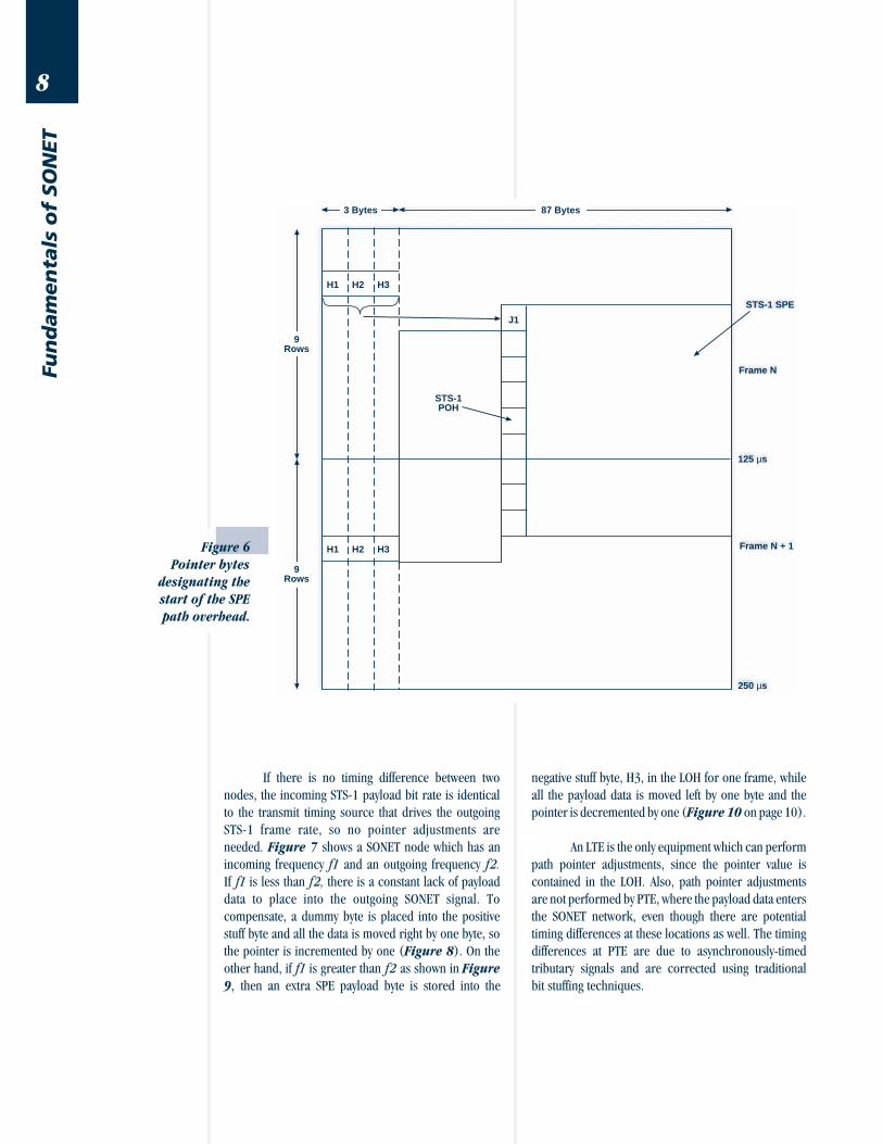
If there is no timing difference between two
nodes, the incoming STS-1 payload bit rate is identical
to the transmit timing source that drives the outgoing
STS-1 frame rate, so no pointer adjustments are
needed. Figure 7 shows a SONET node which has an
incoming frequency f1 and an outgoing frequency f2.
If f1 is less than f2, there is a constant lack of payload
data to place into the outgoing SONET signal. To
compensate, a dummy byte is placed into the positive
stuff byte and all the data is moved right by one byte, so
the pointer is incremented by one (Figure 8). On the
other hand, if f1 is greater than f2 as shown in Figure
9, then an extra SPE payload byte is stored into the
negative stuff byte, H3, in the LOH for one frame, while
all the payload data is moved left by one byte and the
pointer is decremented by one (Figure 10 on page 10).
An LTE is the only equipment which can perform
path pointer adjustments, since the pointer value is
contained in the LOH. Also, path pointer adjustments
are not performed by PTE, where the payload data enters
the SONET network, even though there are potential
timing differences at these locations as well. The timing
differences at PTE are due to asynchronously-timed
tributary signals and are corrected using traditional
bit stuffing techniques.

9
Fun
dam
en
tals o
f SO
NET
SONET Node(LTE)
f2 f1
f1 < f2
H1 H2 H3Start of STS-1 SPE
375 µs
PNEW = P + 1
Positive Stuff Byte(Dummy Byte)
Frame N
Frame N + 1
Frame N + 2
STS-1 Frame
P
Pointer Value (P)
H1 H2 H3
H1 H2 H3
250 µs
125 µs
0 µs
Figure 8
Incrementing the
pointer value.
SONET Node(LTE)
f2 f1
f1 > f2
Figure 7
Node with slower incoming data rate.
Figure 9
Node with faster incoming data rate.
10
Fun
dam
en
tals
of
SO
NET
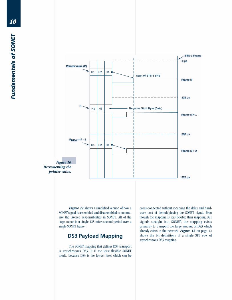
Figure 10
Decrementing the
pointer value.
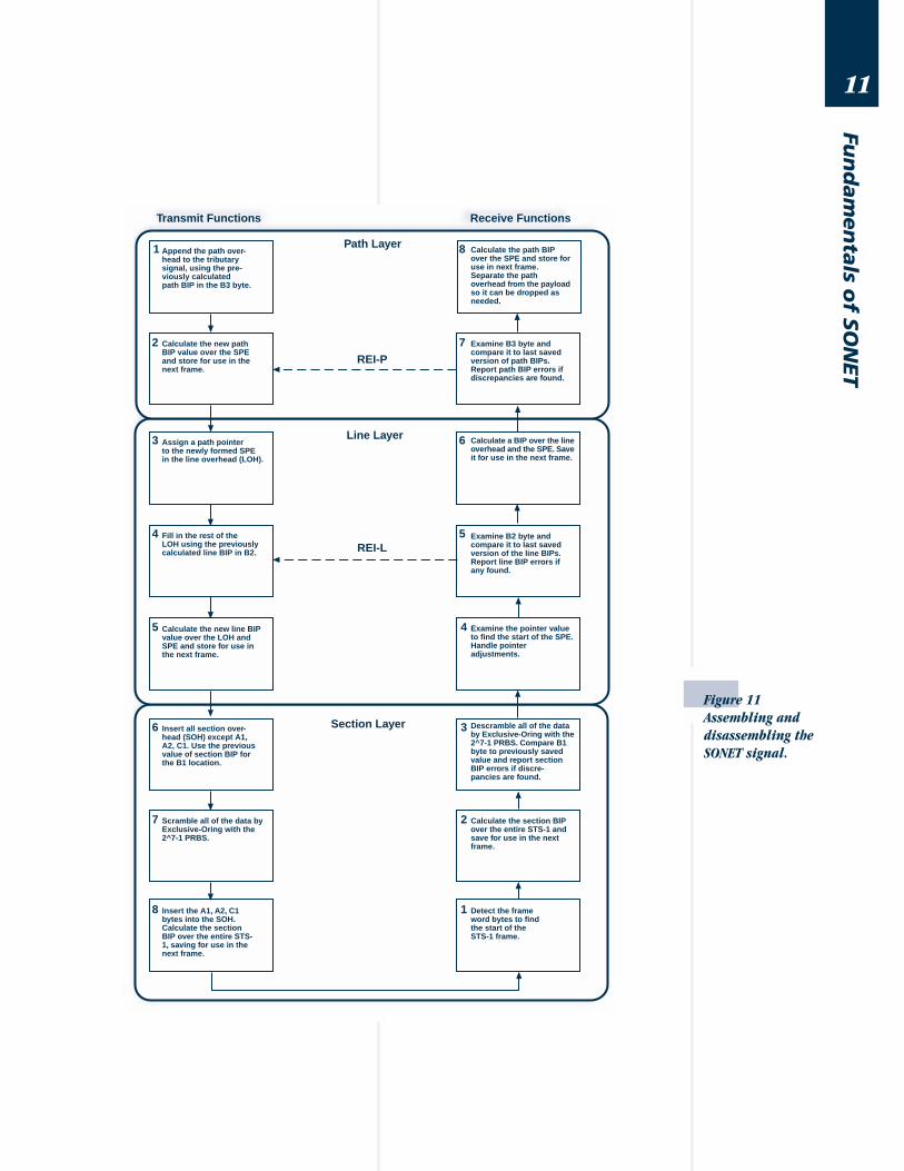
Figure 11 shows a simplified version of how a
SONET signal is assembled and disassembled to summa-
rize the layered responsibilities in SONET. All of the
steps occur in a single 125 microsecond period over a
single SONET frame.
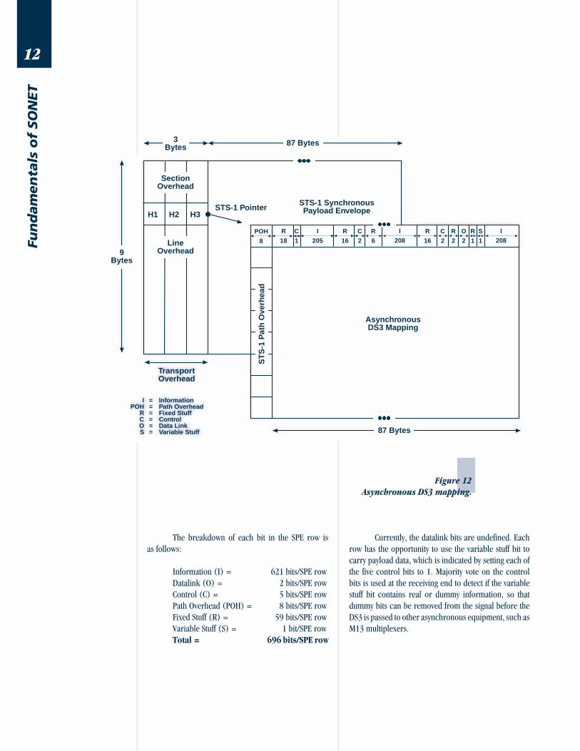
DS3 Payload Mapping
The SONET mapping that defines DS3 transport
is asynchronous DS3. It is the least flexible SONET
mode, because DS3 is the lowest level which can be
cross-connected without incurring the delay and hard-
ware cost of demultiplexing the SONET signal. Even
though the mapping is less flexible than mapping DS1
signals straight into SONET, the mapping exists
primarily to transport the large amount of DS3 which
already exists in the network. Figure 12 on page 12
shows the bit definitions of a single SPE row of
asynchronous DS3 mapping.
Pointer Value (P)
H1 H2 H3Start of STS-1 SPE
375 µs
PNEW = P - 1
Frame N
Frame N + 1
Frame N + 2
STS-1 Frame
PNegative Stuff Byte (Data)H1 H2
H1 H2 H3
250 µs
125 µs
0 µs
11
Fun
dam
en
tals o
f SO
NET
Figure 11
Assembling and
disassembling the
SONET signal.
1
2
3
4
8
7
6
5
5
6
7
8
4
3
2
1
Append the path over-head to the tributarysignal, using the pre-viously calculatedpath BIP in the B3 byte.
Calculate the new pathBIP value over the SPEand store for use in thenext frame.
Assign a path pointerto the newly formed SPEin the line overhead (LOH).
Fill in the rest of theLOH using the previouslycalculated line BIP in B2.
Calculate the new line BIPvalue over the LOH andSPE and store for use inthe next frame.
Insert all section over-head (SOH) except A1,A2, C1. Use the previousvalue of section BIP forthe B1 location.
Scramble all of the data byExclusive-Oring with the2^7-1 PRBS.
Insert the A1, A2, C1bytes into the SOH.Calculate the sectionBIP over the entire STS-1, saving for use in thenext frame.
Detect the frameword bytes to findthe start of theSTS-1 frame.
Calculate the section BIPover the entire STS-1 andsave for use in the nextframe.
Descramble all of the databy Exclusive-Oring with the2^7-1 PRBS. Compare B1byte to previously savedvalue and report sectionBIP errors if discre-pancies are found.
Examine the pointer valueto find the start of the SPE.Handle pointeradjustments.
Examine B2 byte andcompare it to last savedversion of the line BIPs.Report line BIP errors ifany found.
Calculate a BIP over the lineoverhead and the SPE. Saveit for use in the next frame.
Examine B3 byte andcompare it to last savedversion of path BIPs.Report path BIP errors ifdiscrepancies are found.
Calculate the path BIPover the SPE and store foruse in next frame.Separate the pathoverhead from the payloadso it can be dropped asneeded.
Transmit Functions Receive Functions
Path Layer
Line Layer
Section Layer
REI-P
REI-L
12
Fun
dam
en
tals
of
SO
NET
9Bytes
STS-1 SynchronousPayload Envelope
3Bytes 87 Bytes
SectionOverhead
LineOverhead
TransportOverhead
ST
S-1
Pat
h O
verh
ead
87 Bytes
AsynchronousDS3 Mapping
STS-1 PointerH1 H2 H3
IPOH
RCOS
======
InformationPath OverheadFixed StuffControlData LinkVariable Stuff
POH
8
R
18
I
205
R
16
R
6
I
208R
16
I
208C
1
C
2
C
2
R
2
O
2
R
1
S
1
Figure 12
Asynchronous DS3 mapping.
The breakdown of each bit in the SPE row is
as follows:
Information (I) = 621 bits/SPE row
Datalink (O) = 2 bits/SPE row
Control (C) = 5 bits/SPE row
Path Overhead (POH) = 8 bits/SPE row
Fixed Stuff (R) = 59 bits/SPE row
Variable Stuff (S) = 1 bit/SPE row
Total = 696 bits/SPE row
Currently, the datalink bits are undefined. Each
row has the opportunity to use the variable stuff bit to
carry payload data, which is indicated by setting each of
the five control bits to 1. Majority vote on the control
bits is used at the receiving end to detect if the variable
stuff bit contains real or dummy information, so that
dummy bits can be removed from the signal before the
DS3 is passed to other asynchronous equipment, such as
M13 multiplexers.
13
Fun
dam
en
tals o
f SO
NET
Using all of the variable stuff bits for data, it is
possible to calculate the maximum DS3 rate which can
be transmitted with this mapping.
(1 variable bit/row + 621 data bits/row) x
9 rows/frame x 8,000 frames/second = 44.784 Mbps
Calculating the minimum DS3 rate which can be
carried with this mapping is accomplished by calculating
the payload using none of the variable stuff bits.
621 data bits/row x 9 rows/frame x
8,000 frames/second = 44.712 Mbps
Since the nominal DS3 frequency is 44.736
Mbps, the average stuffing rate for this mapping can
be determined.
44.736 Mbps - 44.712 Mbps =
24 kbps of variable stuffing
The average stuff rate for a DS3 implies that
three of the nine variable stuff bits are used in each
frame to carry data. As a side note, the total amount of
overhead that is included with the SPE to transmit the
DS3 is calculated as follows:
(59 fixed stuff bits/row + 2 datalink bits/row +
5 control bits/row + 8 POH bits/row +
1 variable stuff bit/row) x 9 rows/frame x
8,000 frames/second = 5.4 Mbps
Virtual Tributaries
To transport payloads requiring less capacity
than a DS3 signal, the 783-byte SPE is divided into seven
virtual tributary (VT) groups of 12 columns each. The
seven groups are combined with the POH and two fixed
stuff columns to fill the entire STS-1 SPE.
VT Groups = 7 groups x 12 columns/
groups x 9 bytes/column
= 756 bytes
Fixed Stuff = 2 columns x 9 bytes/column
= 18 bytes
Path Overhead = 1 column x 9 bytes/column
= 9 bytes
Total = 783 bytes
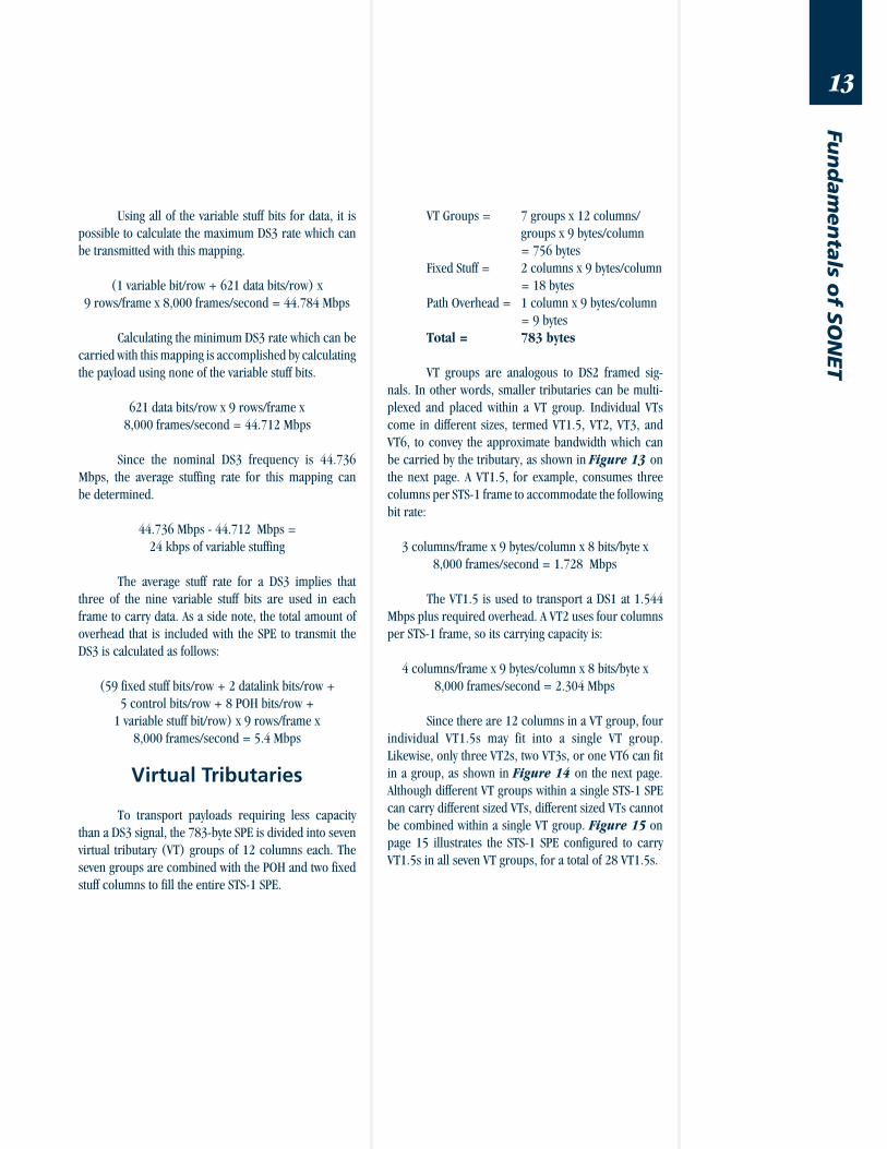
VT groups are analogous to DS2 framed sig-
nals. In other words, smaller tributaries can be multi-
plexed and placed within a VT group. Individual VTs
come in different sizes, termed VT1.5, VT2, VT3, and
VT6, to convey the approximate bandwidth which can
be carried by the tributary, as shown in Figure 13 on
the next page. A VT1.5, for example, consumes three
columns per STS-1 frame to accommodate the following
bit rate:
3 columns/frame x 9 bytes/column x 8 bits/byte x
8,000 frames/second = 1.728 Mbps
The VT1.5 is used to transport a DS1 at 1.544
Mbps plus required overhead. A VT2 uses four columns
per STS-1 frame, so its carrying capacity is:
4 columns/frame x 9 bytes/column x 8 bits/byte x
8,000 frames/second = 2.304 Mbps
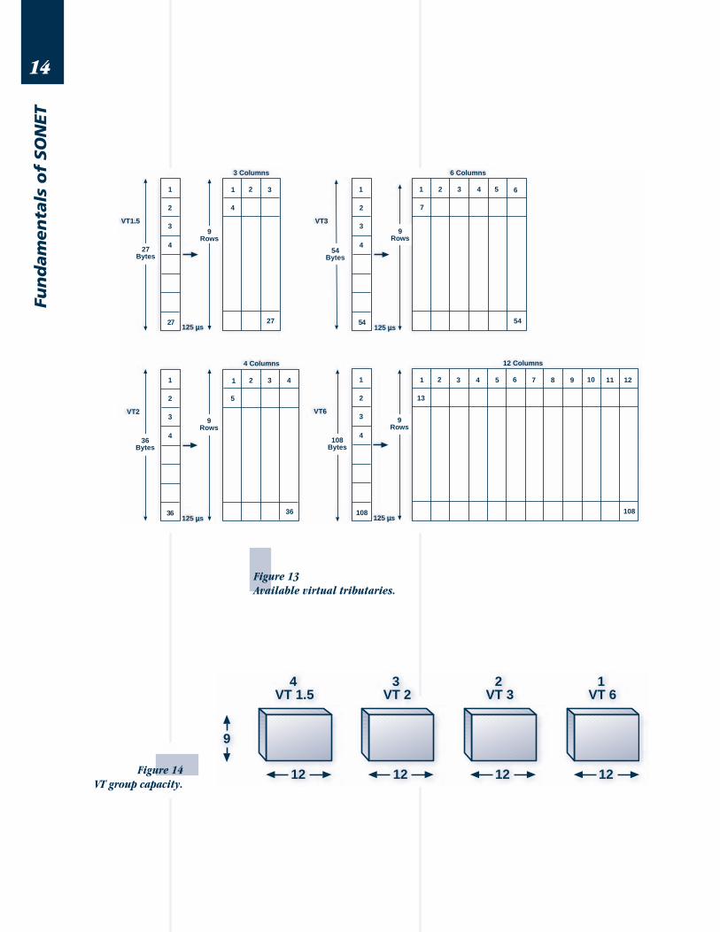
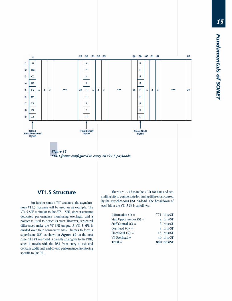
Since there are 12 columns in a VT group, four
individual VT1.5s may fit into a single VT group.
Likewise, only three VT2s, two VT3s, or one VT6 can fit
in a group, as shown in Figure 14 on the next page.
Although different VT groups within a single STS-1 SPE
can carry different sized VTs, different sized VTs cannot
be combined within a single VT group. Figure 15 on
page 15 illustrates the STS-1 SPE configured to carry
VT1.5s in all seven VT groups, for a total of 28 VT1.5s.
14
Fun
dam
en
tals
of
SO
NET
9
12 12 12
4 VT 1.5
3 VT 2
2 VT 3
1 VT 6
12
1
2
3
4
27
1 2 3
4
27
9Rows
27Bytes
VT1.5
3 Columns
125 µs
1
2
3
4
36
1 2 3
5
36
9Rows
36Bytes
VT2
4 Columns
4
125 µs
1
2
3
4
54
1 2 3
7
54
9Rows
54Bytes
VT3
6 Columns
125 µs
1
2
3
4
108
1 2 3
13
108
9Rows
108Bytes
VT6
12 Columns
4
4 5 6
5 6 7 8 9 10 11 12
125 µs
Figure 14
VT group capacity.
Figure 13
Available virtual tributaries.
15
Fun
dam
en
tals o
f SO
NET
J1
B3
C2
G1
F2
H4
Z3
Z4
Z5
1
2
3
4
5
6
7
8
9
R
R
R
R
R
R
R
R
R
R
R
R
R
R
R
R
R
R
1 2 3 1 2 328 1 2 328 28
30 5931 32 3329 60 61 6258 871
STS-1Path Overhead
Bytes
Fixed StuffBytes
Fixed StuffBytes
Figure 15
STS-1 frame configured to carry 28 VT1.5 payloads.
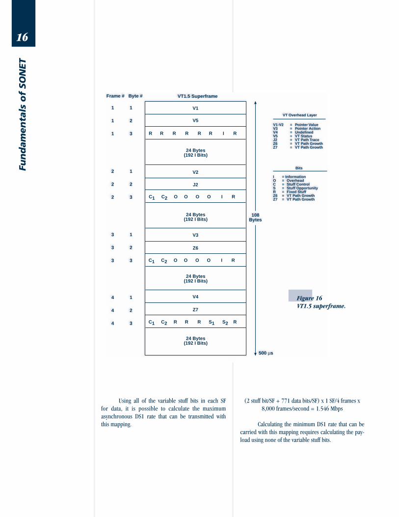
VT1.5 Structure
For further study of VT structure, the asynchro-
nous VT1.5 mapping will be used an an example. The
VT1.5 SPE is similar to the STS-1 SPE, since it contains
dedicated performance monitoring overhead, and a
pointer is used to detect its start. However, structural
differences make the VT SPE unique. A VT1.5 SPE is
divided over four consecutive STS-1 frames to form a
superframe (SF) as shown in Figure 16 on the next
page. The VT overhead is directly analogous to the POH,
since it travels with the DS1 from entry to exit and
contains additional end-to-end performance monitoring
specific to the DS1.
There are 771 bits in the VT SF for data and two
stuffing bits to compensate for timing differences caused
by the asynchronous DS1 payload. The breakdown of
each bit in the VT1.5 SF is as follows:
Information (I) = 771 bits/SF
Stuff Opportunities (S) = 2 bits/SF
Stuff Control (C) = 6 bits/SF
Overhead (O) = 8 bits/SF
Fixed Stuff (R) = 13 bits/SF
VT Overhead = 40 bits/SF
Total = 840 bits/SF
16
Fun
dam
en
tals
of
SO
NET
VT1.5 Superframe
V1
V5
R R R R R R I R
24 Bytes(192 I Bits)
V2
C1 C2 O O O O I R
24 Bytes(192 I Bits)
V3
C1 C2 O O O O I R
24 Bytes(192 I Bits)
V4
C1 C2 R R R S1 S2 R
24 Bytes(192 I Bits)
500 µs
108Bytes
Frame # Byte #
1 1
1 2
1 3
2 1
2 2
2 3
3 1
3 2
3 3
4 1
4 2
4 3
VT Overhead Layer
V1-V2 = Pointer ValueV3 = Pointer ActionV4 = UndefinedV5 = VT StatusJ2 = VT Path TraceZ6 = VT Path GrowthZ7 = VT Path Growth
Bits
I = InformationO = OverheadC = Stuff ControlS = Stuff OpportunityR = Fixed StuffZ6 = VT Path GrowthZ7 = VT Path Growth
J2
Z6
Z7
Figure 16
VT1.5 superframe.
Using all of the variable stuff bits in each SF
for data, it is possible to calculate the maximum
asynchronous DS1 rate that can be transmitted with
this mapping.
(2 stuff bit/SF + 771 data bits/SF) x 1 SF/4 frames x
8,000 frames/second = 1.546 Mbps
Calculating the minimum DS1 rate that can be
carried with this mapping requires calculating the pay-
load using none of the variable stuff bits.
17
Fun
dam
en
tals o
f SO
NET
771 data bits/SF x 1 SF/4 frames x
8,000 frames/second = 1.542 Mbps
Since the nominal DS1 frequency is 1.544
Mbps, the average stuffing rate for this mapping can
be determined.
1.544 Mbps - 1.542 Mbps = 2 kbps of variable stuffing
A 2 kbps average stuff rate indicates an average
use of one stuff bit per SF.
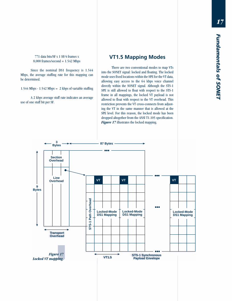
VT1.5 Mapping Modes
There are two conventional modes to map VTs
into the SONET signal: locked and floating. The locked
mode uses fixed locations within the SPE for the VT data,
allowing easy access to the 64 kbps voice channel
directly within the SONET signal. Although the STS-1
SPE is still allowed to float with respect to the STS-1
frame in all mappings, the locked VT payload is not
allowed to float with respect to the VT overhead. This
restriction prevents the VT cross-connects from adjust-
ing the VT in the same manner that is allowed at the
SPE level. For this reason, the locked mode has been
dropped altogether from the ANSI T1.105 specification.
Figure 17 illustrates the locked mapping.
Figure 17
Locked VT mapping.
9Bytes
3Bytes 87 Bytes
SectionOverhead
LineOverhead
TransportOverhead
VT
VT1.5STS-1 SynchronousPayload Envelope
VT VT
Locked-ModeDS1 Mapping
ST
S-1
Pat
h O
verh
ead
Locked-ModeDS1 Mapping
Locked-ModeDS1 Mapping
18
Fun
dam
en
tals
of
SO
NET
9Bytes
STS-1 SynchronousPayload Envelope
3Bytes
87 Bytes
SectionOverhead
LineOverhead
TransportOverhead
ST
S-1
Pat
h O
verh
ead
STS-1 Pointer
1
VT Pointer
2
3125 µs
VT Floating Mode
H1 H2 H3
VT
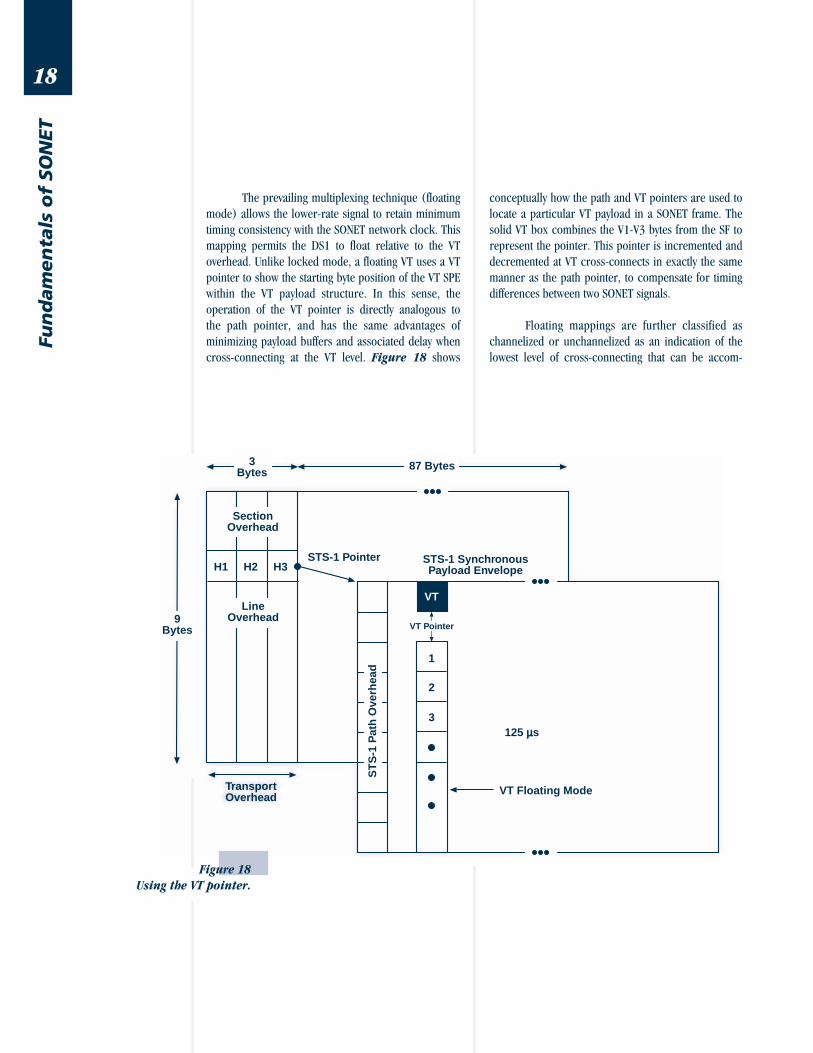
The prevailing multiplexing technique (floating
mode) allows the lower-rate signal to retain minimum
timing consistency with the SONET network clock. This
mapping permits the DS1 to float relative to the VT
overhead. Unlike locked mode, a floating VT uses a VT
pointer to show the starting byte position of the VT SPE
within the VT payload structure. In this sense, the
operation of the VT pointer is directly analogous to
the path pointer, and has the same advantages of
minimizing payload buffers and associated delay when
cross-connecting at the VT level. Figure 18 shows
conceptually how the path and VT pointers are used to
locate a particular VT payload in a SONET frame. The
solid VT box combines the V1-V3 bytes from the SF to
represent the pointer. This pointer is incremented and
decremented at VT cross-connects in exactly the same
manner as the path pointer, to compensate for timing
differences between two SONET signals.
Floating mappings are further classified as
channelized or unchannelized as an indication of the
lowest level of cross-connecting that can be accom-
Figure 18
Using the VT pointer.

19
Fun
dam
en
tals o
f SO
NET
9Bytes
3Bytes
87 Bytes
SectionOverhead
LineOverhead
TransportOverhead
VT
VT1.5
STS-1 SynchronousPayload Envelope
VT VT
ST
S-1
Pat
h O
verh
ead
Byt
e-S
ynch
ron
ou
sD
S1
Map
pin
g
Byt
e-S
ynch
ron
ou
sD
S1
Map
pin
g
Byt
e-S
ynch
ron
ou
sD
S1
Map
pin
g
VT1.5
plished with the mapping. The channelized (byte-
synchronous) mapping, as shown in Figure 19, is
observable at the DS0 level and is consequently very
popular in integrated digital loop carrier (IDLC) app-
lications. Since the DS0s can be removed and inserted
directly into the SONET signal without the typical cost
and delay of an additional 1/0 cross-connect, cost
savings can be realized in the deployment of DS0 groom-
ing architectures. This capability technically would
allow equipment to route calls through the local loop
without having the call travel through the main switch
in the central office. When the billing software is able
to support this application, this technology will be-
come more widespread. Additionally, the extension of
SONET into the local loop brings with it added protec-
tion and OAM&P messaging. The disadvantage of this
Figure 19
Byte synchronous
floating mode.
20
Fun
dam
en
tals
of
SO
NET
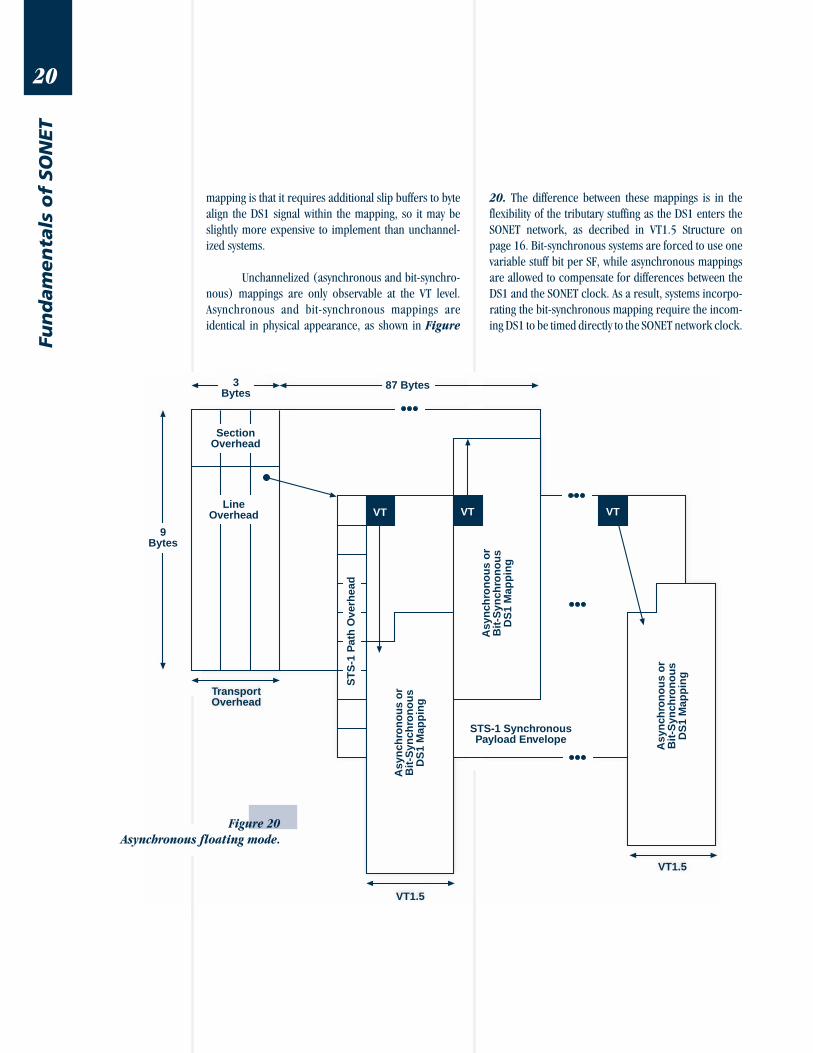
mapping is that it requires additional slip buffers to byte
align the DS1 signal within the mapping, so it may be
slightly more expensive to implement than unchannel-
ized systems.
Unchannelized (asynchronous and bit-synchro-
nous) mappings are only observable at the VT level.
Asynchronous and bit-synchronous mappings are
identical in physical appearance, as shown in Figure
20. The difference between these mappings is in the
flexibility of the tributary stuffing as the DS1 enters the
SONET network, as decribed in VT1.5 Structure on
page 16. Bit-synchronous systems are forced to use one
variable stuff bit per SF, while asynchronous mappings
are allowed to compensate for differences between the
DS1 and the SONET clock. As a result, systems incorpo-
rating the bit-synchronous mapping require the incom-
ing DS1 to be timed directly to the SONET network clock.
Figure 20
Asynchronous floating mode.
9Bytes
3Bytes
87 Bytes
SectionOverhead
LineOverhead
TransportOverhead
ST
S-1
Pat
h O
verh
ead
VT
VT1.5
Asy
nch
ron
ou
s o
rB
it-S
ynch
ron
ou
sD
S1
Map
pin
g
STS-1 SynchronousPayload Envelope
Asy
nch
ron
ou
s o
rB
it-S
ynch
ron
ou
sD
S1
Map
pin
gVT
Asy
nch
ron
ou
s o
rB
it-S
ynch
ron
ou
sD
S1
Map
pin
g
VT
VT1.5
21
Fun
dam
en
tals o
f SO
NET
There are no slip buffers required to implement these
mappings, so equipment may be less expensive, making
it popular in long distance applications. For access to
the DS0 channels, a 1/0 cross-connect is required for
both of these mappings, however transport systems are
generally concerned with cross-connecting at higher
rates than voice. The efficiency and flexibility of the
asynchronous mapping makes it the most common.
Protection Switching
With upwards of 32 thousand telephone calls
over a single OC-48, disaster recovery is substantially
more important to service providers today than it has
been in the past. Therefore, a major requirement of
any future widely deployed transmission standard is the
ability to withstand catastrophic failures without
severely affecting service. The SONET network is able to
weather these failures due to deployment of SONET
ring architectures and automatic protection switching
(APS) algorithms. These mechanisms allow live traffic to
flow through a new path whenever the old path is dis-
rupted or becomes degraded.
Linear Systems
A linear (point-to-point) network can be imple-
mented with working and protect (or primary and sec-
ondary) fibers deployed in different locations (route
diversity). Also called 1+1, both the working and
protect lines carry identical traffic, permitting the re-
ceiving end to monitor the status of each line in real time.
If the working line becomes degraded or is disrupted, the
receiver simply switches to the protect fiber. The de-
graded threshold is programmable and is usually set at a
line BIP error rate of 1E-7 or 8. This type of switching is
also called “tail-switched,” since switching decisions
take place at the tail (receiving) end of a signal. Unfortu-
nately the cost of fiber, receivers, and transmitters is
doubled between every protected node, as compared to
a non-protected system.
The cost of this protection can be reduced by
using a 1:n architecture, where n is between 1 and 14.
This architecture is similar to 1+1 with two major differ-
ences. First, even in a 1:1 architecture, the protect line
is not carrying the identical traffic so the transmitting
end must request a switch. Second, since there is one
protect line for n working lines, there is a possibility
that a working line will not be granted a switch. The
head (transmitting) end determines the priority of
the requestor and either honors or ignores the
receiver’s request to switch, hence this architecture is
also called “head-switched.”
Unidirectional PathSwitched Rings
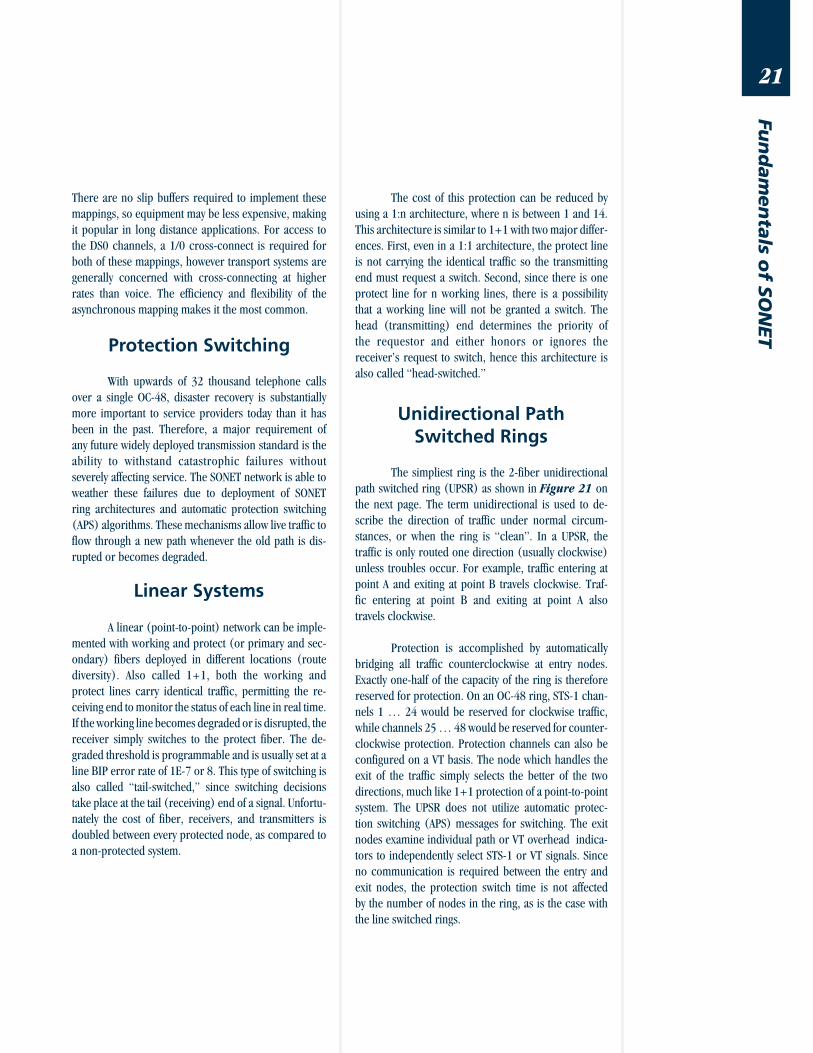
The simpliest ring is the 2-fiber unidirectional
path switched ring (UPSR) as shown in Figure 21 on
the next page. The term unidirectional is used to de-
scribe the direction of traffic under normal circum-
stances, or when the ring is “clean”. In a UPSR, the
traffic is only routed one direction (usually clockwise)
unless troubles occur. For example, traffic entering at
point A and exiting at point B travels clockwise. Traf-
fic entering at point B and exiting at point A also
travels clockwise.
Protection is accomplished by automatically
bridging all traffic counterclockwise at entry nodes.
Exactly one-half of the capacity of the ring is therefore
reserved for protection. On an OC-48 ring, STS-1 chan-
nels 1 … 24 would be reserved for clockwise traffic,
while channels 25 … 48 would be reserved for counter-
clockwise protection. Protection channels can also be
configured on a VT basis. The node which handles the
exit of the traffic simply selects the better of the two
directions, much like 1+1 protection of a point-to-point
system. The UPSR does not utilize automatic protec-
tion switching (APS) messages for switching. The exit
nodes examine individual path or VT overhead indica-
tors to independently select STS-1 or VT signals. Since
no communication is required between the entry and
exit nodes, the protection switch time is not affected
by the number of nodes in the ring, as is the case with
the line switched rings.

22
Fun
dam
en
tals
of
SO
NET
Figure 21
Unidirectional path
switched ring.
Bidirectional LineSwitched Rings
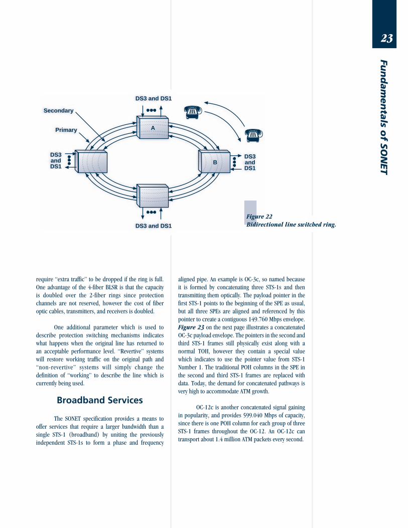
Unlike UPSR, a bidirectional line switched ring
(BLSR) may be architected with either 2-fibers or the
4-fiber ring as shown in Figure 22. A 2-fiber BLSR is
similar to a UPSR, except that traffic is routed in both
directions around the ring under normal circumstances.
For example, traffic entering at point A and exiting at
point B travels clockwise, while traffic entering at point B
and exiting at point A travels counterclockwise. This
method allows the most efficient use of deployed equip-
ment and fiber resources.
In a BLSR, the STS-1 or VT traffic is not bridged
in the opposite direction unless APS signaling between
the entry and the exit node specifically requests the
channel be placed on protection. The APS messaging
may be accompanied by further instructions contained
in the section DCC. Since the BLSR requires communi-
cation, a switch time requirement of 50 milliseconds
restricts the BLSR to 16 nodes. An advantage is that
bidirectional traffic allows network planners to periodi-
cally reroute signals for purposes of load-balancing.
A 4-fiber BLSR uses two types of protection
switching: span switching and ring switching. Normal
traffic is routed exactly as the 2-fiber BLSR, however if
the transmit and receive fiber pair bundle is cut or
degraded between points A and B, a “span switch”
occurs. The span switch routes traffic over the protected
fiber pair much like 1:1 protection on a point-to-point
system, and no directional re-routing is required. If
both fiber pairs are degraded or a node fails, then a
“ring switch” occurs by routing traffic away from the
failure. Unlike the UPSR, a BLSR examines only LOH
performance indications to determine quality of service.
The monitoring does not extend to the path or VT layer.
Span switching and ring switching can be used
simultaneously in a 4-fiber BLSR to protect traffic in the
event of multiple failures on the same ring. If both of
these switching methods are used, the ring switch will
DS3 and DS1
A
DS3 and DS1
DS3andDS1
DS3andDS1
Secondary
Primary
B
23
Fun
dam
en
tals o
f SO
NET
DS3 and DS1
A
DS3 and DS1
DS3andDS1
DS3andDS1
Secondary
Primary
B
Figure 22
Bidirectional line switched ring.
require “extra traffic” to be dropped if the ring is full.
One advantage of the 4-fiber BLSR is that the capacity
is doubled over the 2-fiber rings since protection
channels are not reserved, however the cost of fiber
optic cables, transmitters, and receivers is doubled.
One additional parameter which is used to
describe protection switching mechanisms indicates
what happens when the original line has returned to
an acceptable performance level. “Revertive” systems
will restore working traffic on the original path and
“non-revertive” systems will simply change the
definition of “working” to describe the line which is
currently being used.
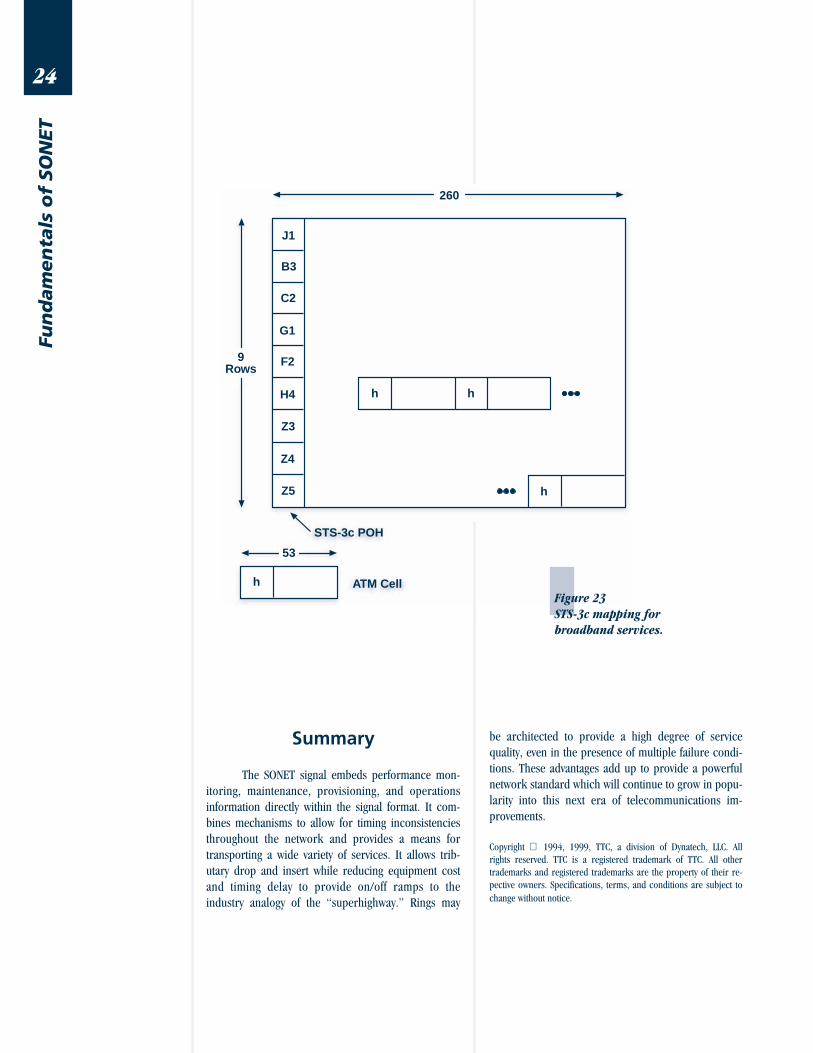
Broadband Services
The SONET specification provides a means to
offer services that require a larger bandwidth than a
single STS-1 (broadband) by uniting the previously
independent STS-1s to form a phase and frequency
aligned pipe. An example is OC-3c, so named because
it is formed by concatenating three STS-1s and then
transmitting them optically. The payload pointer in the
first STS-1 points to the beginning of the SPE as usual,
but all three SPEs are aligned and referenced by this
pointer to create a contiguous 149.760 Mbps envelope.
Figure 23 on the next page illustrates a concatenated
OC-3c payload envelope. The pointers in the second and
third STS-1 frames still physically exist along with a
normal TOH, however they contain a special value
which indicates to use the pointer value from STS-1
Number 1. The traditional POH columns in the SPE in
the second and third STS-1 frames are replaced with
data. Today, the demand for concatenated pathways is
very high to accommodate ATM growth.
OC-12c is another concatenated signal gaining
in popularity, and provides 599.040 Mbps of capacity,
since there is one POH column for each group of three
STS-1 frames throughout the OC-12. An OC-12c can
transport about 1.4 million ATM packets every second.
24
Fun
dam
en
tals
of
SO
NET
Figure 23
STS-3c mapping for
broadband services.
Summary
The SONET signal embeds performance mon-
itoring, maintenance, provisioning, and operations
information directly within the signal format. It com-
bines mechanisms to allow for timing inconsistencies
throughout the network and provides a means for
transporting a wide variety of services. It allows trib-
utary drop and insert while reducing equipment cost
and timing delay to provide on/off ramps to the
industry analogy of the “superhighway.” Rings may
be architected to provide a high degree of service
quality, even in the presence of multiple failure condi-
tions. These advantages add up to provide a powerful
network standard which will continue to grow in popu-
larity into this next era of telecommunications im-
provements.
Copyright 1994, 1999, TTC, a division of Dynatech, LLC. All
rights reserved. TTC is a registered trademark of TTC. All other
trademarks and registered trademarks are the property of their re-
pective owners. Specifications, terms, and conditions are subject to
change without notice.
260
J1
h
9Rows
STS-3c POH
B3
C2
G1
F2
H4
Z3
Z4
Z5
h
h
h ATM Cell
53
25
Fun
dam
en
tals o
f SO
NET
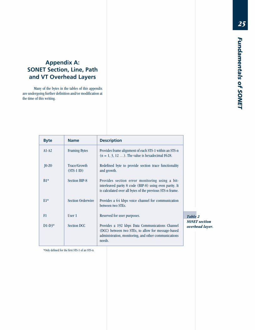
Table 2
SONET section
overhead layer.
Appendix A:SONET Section, Line, Pathand VT Overhead Layers
Many of the bytes in the tables of this appendix
are undergoing further definition and/or modification at
the time of this writing.
Byte Name Description
A1-A2 Framing Bytes Provides frame alignment of each STS-1 within an STS-n
(n = 1, 3, 12 …). The value is hexadecimal F628.
J0-Z0 Trace/Growth Redefined byte to provide section trace functionality
(STS-1 ID) and growth.
B1* Section BIP-8 Provides section error monitoring using a bit-
interleaved parity 8 code (BIP-8) using even parity. It
is calculated over all bytes of the previous STS-n frame.
E1* Section Orderwire Provides a 64 kbps voice channel for communication
between two STEs.
F1 User 1 Reserved for user purposes.
D1-D3* Section DCC Provides a 192 kbps Data Communications Channel
(DCC) between two STEs, to allow for message-based
administration, monitoring, and other communications
needs.
*Only defined for the first STS-1 of an STS-n.
26
Fun
dam
en
tals
of
SO
NET
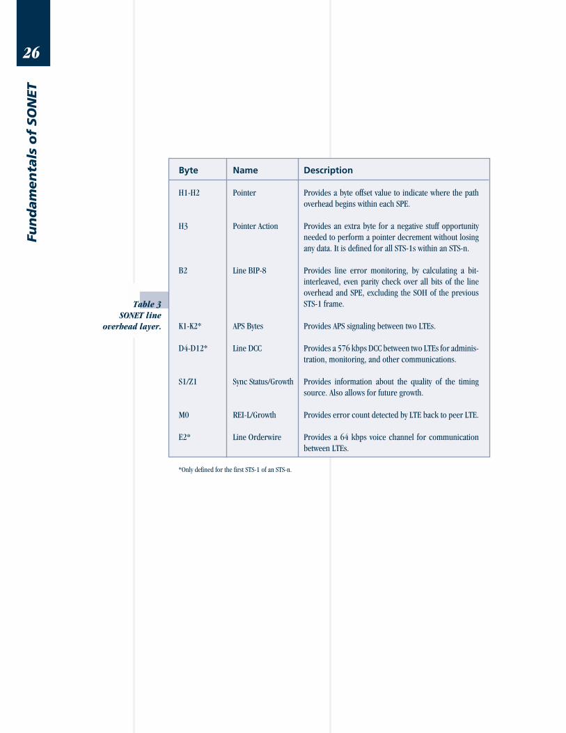
Table 3
SONET line
overhead layer.
Byte Name Description
H1-H2 Pointer Provides a byte offset value to indicate where the path
overhead begins within each SPE.
H3 Pointer Action Provides an extra byte for a negative stuff opportunity
needed to perform a pointer decrement without losing
any data. It is defined for all STS-1s within an STS-n.
B2 Line BIP-8 Provides line error monitoring, by calculating a bit-
interleaved, even parity check over all bits of the line
overhead and SPE, excluding the SOH of the previous
STS-1 frame.
K1-K2* APS Bytes Provides APS signaling between two LTEs.
D4-D12* Line DCC Provides a 576 kbps DCC between two LTEs for adminis-
tration, monitoring, and other communications.
S1/Z1 Sync Status/Growth Provides information about the quality of the timing
source. Also allows for future growth.
M0 REI-L/Growth Provides error count detected by LTE back to peer LTE.
E2* Line Orderwire Provides a 64 kbps voice channel for communication
between LTEs.
*Only defined for the first STS-1 of an STS-n.
27
Fun
dam
en
tals o
f SO
NET
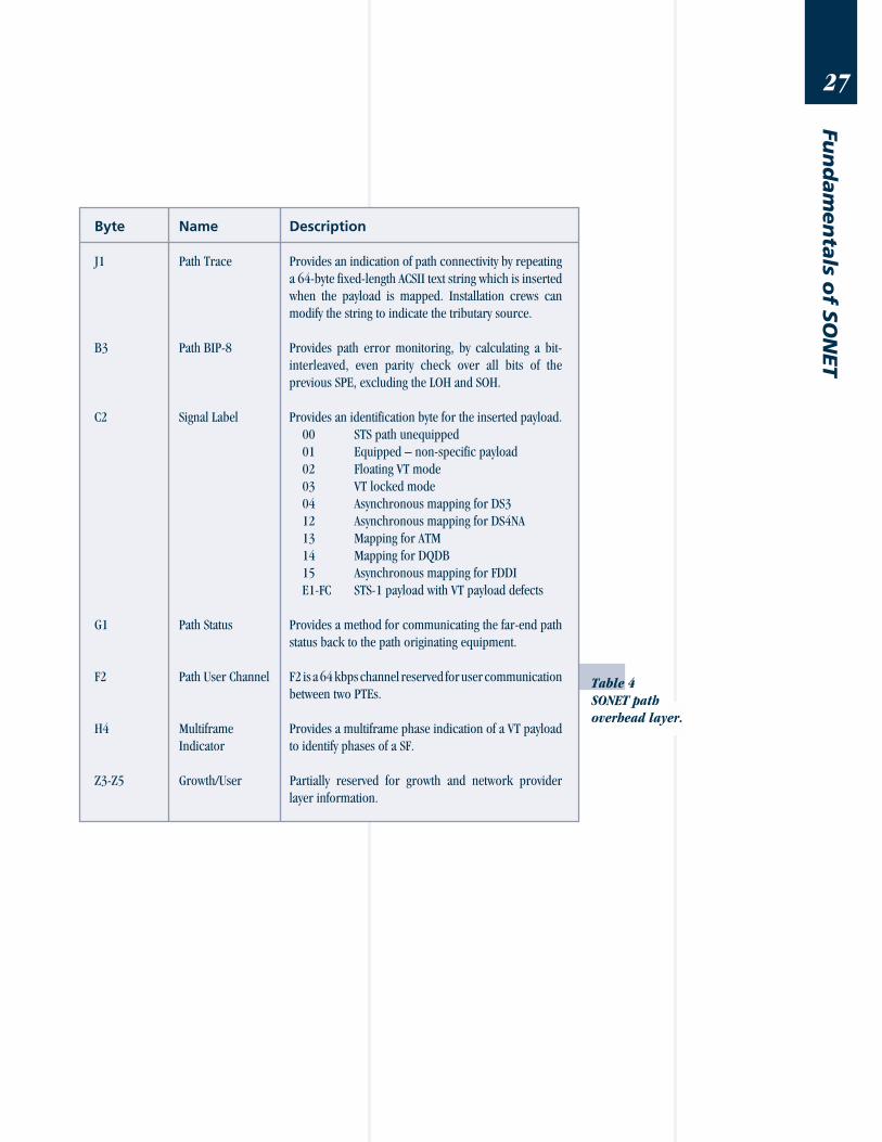
Table 4
SONET path
overhead layer.
Byte Name Description
J1 Path Trace Provides an indication of path connectivity by repeating
a 64-byte fixed-length ACSII text string which is inserted
when the payload is mapped. Installation crews can
modify the string to indicate the tributary source.
B3 Path BIP-8 Provides path error monitoring, by calculating a bit-
interleaved, even parity check over all bits of the
previous SPE, excluding the LOH and SOH.
C2 Signal Label Provides an identification byte for the inserted payload.
00 STS path unequipped
01 Equipped – non-specific payload
02 Floating VT mode
03 VT locked mode
04 Asynchronous mapping for DS3
12 Asynchronous mapping for DS4NA
13 Mapping for ATM
14 Mapping for DQDB
15 Asynchronous mapping for FDDI
E1-FC STS-1 payload with VT payload defects
G1 Path Status Provides a method for communicating the far-end path
status back to the path originating equipment.
F2 Path User Channel F2 is a 64 kbps channel reserved for user communication
between two PTEs.
H4 Multiframe Provides a multiframe phase indication of a VT payload
Indicator to identify phases of a SF.
Z3-Z5 Growth/User Partially reserved for growth and network provider
layer information.
28
Fun
dam
en
tals
of
SO
NET
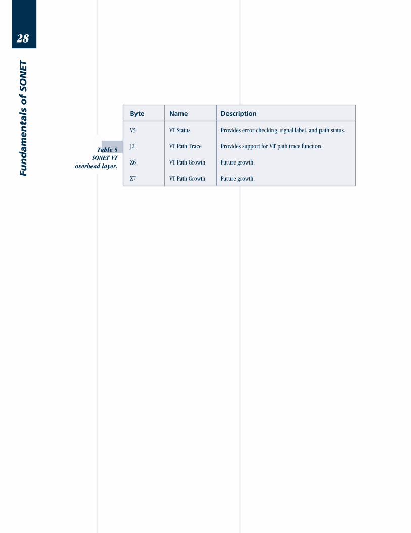
Table 5
SONET VT
overhead layer.
Byte Name Description
V5 VT Status Provides error checking, signal label, and path status.
J2 VT Path Trace Provides support for VT path trace function.
Z6 VT Path Growth Future growth.
Z7 VT Path Growth Future growth.

29
Fun
dam
en
tals o
f SO
NET
!! DO NOT PRINT THIS PAGE !!
30
Fun
dam
en
tals
of
SO
NET
9Rows
B B
B denotGlobal Headquarters
20400 Observation Drive
Germantown, Maryland 20876-4023 USA
Toll Free 1-800-638-2049 • Tel +1-301-353-1550 • Fax +1-301-353-0234
www.acterna.com
SONETTN-D-2/01
31
Fun
dam
en
tals o
f SO
NET
The Fu
nd
am
en
tals o
f SO
NET
Tech
nica
l No
te
90 Bytes
B
87B
125 µs
Transport
Overhead
STS-1 Envelope Capacity
tes an 8-bit byte.