The Freeform Fabrication of Structurally Optimized and ...edge.rit.edu/content/P10551/public/SFF/SFF...
10
The Freeform Fabrication of Structurally Optimized and Complexly-Shaped Metal Tubular Components Dr. Kevin Chaite Rotheroe, Freeform Design & Manufacturing Research Studio, New York School of Architecture & Building Research Council, University of Illinois, Urbana-Champaign Abstract The service conditions of many structural frames composed of tubular metal components would ideally warrant the use of high strength-to-weight ratio components with shapes and internal geometries that respond to context-specific structural requirements. Commercially available and emerging solid freeform fabrication technologies can be utilized to indirectly or directly manufacture metal tubular structural components with optimizing features that cannot otherwise be manufactured. The results of prototyping experiments demonstrating the viability and potential of this application of additive manufacturing will be presented. This presentation will discuss successful prototype 356 aluminum and 316 stainless steel internally reinforced freeform tubular components manufactured indirectly using expendable patterns made by selective laser sintering and 3D printing. The application of laser and metal powder based freeform fabrication technologies that provide superior material properties will also be discussed, especially in terms of requirements for multi-axis deposition and sophisticated path planning software, and the implications of voxel- or layer-based functionally gradient materials. 1.0 Introduction The term tube is conventionally understood to refer to a hollow lineal component with a constant cross-sectional shape and size. Constant cross-sectional configuration, however, is not inherent in the definition. Complex hydroformed automotive chassis components, for example, are referred to as being tubular, and are created by deforming conventional metal tubes. Conventional roll-formed or extruded metal tubes can be considered to exhibit generally optimized strength-to-weight ratios achieved by a combination of hollowed simple cross- sectional geometry and particular material properties. 1.1 Classifying Structural Optimization The author has defined two general classes of structural optimization as it pertains to components utilized in structural frames. Externally optimized components are those that generally maximize strength-to-weight or strength-to-material usage ratios with features that are visible on the exterior of the component. Rolled steel sections produced to industry standards such as angles or ‘I’ beams are common examples exhibiting simple cross-sectional geometry. Non- hollow extrusions also fall into this category. Examples of much more complex externally optimized components include subtractively formed bulkheads such as those found in aircraft fuselage frames: such components can feature a wide variety of complex product-specific web, flange, and rib configurations. A few research and/or commercial organizations are presently 47
Transcript of The Freeform Fabrication of Structurally Optimized and ...edge.rit.edu/content/P10551/public/SFF/SFF...
The Freeform Fabrication of Structurally Optimized and Complexly-ShapedMetal Tubular Components
Dr. Kevin Chaite Rotheroe,Freeform Design & Manufacturing Research Studio, New York
School of Architecture & Building Research Council, University of Illinois, Urbana-Champaign
Abstract
The service conditions of many structural frames composed of tubular metal components wouldideally warrant the use of high strength-to-weight ratio components with shapes and internalgeometries that respond to context-specific structural requirements. Commercially available andemerging solid freeform fabrication technologies can be utilized to indirectly or directlymanufacture metal tubular structural components with optimizing features that cannot otherwisebe manufactured. The results of prototyping experiments demonstrating the viability andpotential of this application of additive manufacturing will be presented. This presentation willdiscuss successful prototype 356 aluminum and 316 stainless steel internally reinforced freeformtubular components manufactured indirectly using expendable patterns made by selective lasersintering and 3D printing. The application of laser and metal powder based freeform fabricationtechnologies that provide superior material properties will also be discussed, especially in termsof requirements for multi-axis deposition and sophisticated path planning software, and theimplications of voxel- or layer-based functionally gradient materials.
1.0 Introduction
The term tube is conventionally understood to refer to a hollow lineal component with a constantcross-sectional shape and size. Constant cross-sectional configuration, however, is not inherentin the definition. Complex hydroformed automotive chassis components, for example, arereferred to as being tubular, and are created by deforming conventional metal tubes.
Conventional roll-formed or extruded metal tubes can be considered to exhibit generallyoptimized strength-to-weight ratios achieved by a combination of hollowed simple cross-sectional geometry and particular material properties.
1.1 Classifying Structural Optimization
The author has defined two general classes of structural optimization as it pertains to componentsutilized in structural frames. Externally optimized components are those that generallymaximize strength-to-weight or strength-to-material usage ratios with features that are visible onthe exterior of the component. Rolled steel sections produced to industry standards such asangles or ‘I’ beams are common examples exhibiting simple cross-sectional geometry. Non-hollow extrusions also fall into this category. Examples of much more complex externallyoptimized components include subtractively formed bulkheads such as those found in aircraftfuselage frames: such components can feature a wide variety of complex product-specific web,flange, and rib configurations. A few research and/or commercial organizations are presently
47

developing hybrid additive and subtractive methods for making complex externally optimizedcomponents such as bulkheads. AeroMet Corporation, for example, has developed gantry-configured 3-axis deposition of titanium onto webs that are pre- (or post-) cut from titaniumsheets. This deposition process forms ribs and flanges, and required surface accuracy is achievedby CNC machining the deposited material.
Internally optimized components are those that generally maximize strength-to-weight orstrength-to-material usage ratios using features that are formed internally and/or are not visibleon the exterior of the component, except possibly at open ends or via external shape, as with ahydroformed member. Conventional tubes are very basic internally optimized components inthat their hollowness is not visible unless holes or perforations have been created. Extrusion isfrequently used to manufacture much more complex internally optimized components, and manyof these components, such as those found in aluminum building fenestration systems or in thechasses of manufacturing equipment, can feature highly complicated cross-sectional geometry.The extent, however, to which complex internally optimized components such as extrusions canobtain maximum strength-to-weight ratios and respond to context-specific service conditions, islimited by formal constraints inherent in available manufacturing methods. Additive processes,especially direct metal deposition methods, have significant potential to circumvent theseconstraints and enable further optimization of metal structural frame components.
The general constraints on product form inherent in established manufacturing processes arelisted below. A taxonomy of all available manufacturing processes for making metal structuralcomponents is presented in Figure 1. This taxonomy conventionally classifies manufacturingprocesses as mass-conserving or mass-reducing, but then sub-classifies processes based on thegeometric constraints they impose on product design.
1. Equipment-based constraints. The formal output (e.g. possible product size) of a givenmanufacturing process is limited by at least one piece of available required equipment.
2. Motion-based constraints:
Rotational Motion results in axially-constrained product geometry. Lineal Motion (centralized applied force) results in products with a constant cross-sectional
configuration (e.g. extrusion, rolling). Surface Distributed Lineal Motion (distributed applied force) can only produce parts
without undercut or re-entrant features (e.g. stamping and forging). Multi-Axis Motion cannot access or create significant internal features when utilized in
conjunction with subtractive manufacturing methods.
3. Tooling-based constraints. The need to remove mandrels, re-usable patterns, dies, re-usablemolds, and required fixtures, as well as the components (products) formed with these tools,significantly limits the potential geometry of products, or, in other words, the extent to whichoptimizing features can be incorporated into designs.
4. Process Based Constraints. Workpiece access and material removal requirements (e.g.removal of expendable cores, internal expendable molds, support powder or support stucturesfrom internal cavities) can constrain the extent to which product designs might be fullyoptimized.
48

3
PowderedMetallurgy
Compaction
Deformation
Die Forming
Consolidation
Casting
Mass ConservingDirect Additive Processes
6
5
Metal Solid Freeform Fabrication
Mass ConservingIndirect Tool-Dependent Processes
Manufacturing Processes for Structural Metal Components
Ceramic Mold
Expendable Mold
Bonded Sand Mold
Lost Foam Process
Patternless Sand Casting
Green Sand Molding
Shell-Mold Casting
Counter-GravityLow-Pressure Casting
No-Bake Resin Binder
Cold Box Resin Binder
Hybrid Ceramic/Sand Mold
Replicast Process7
Dry Sand Mold
V-Process (Vacuum)8
Reusable Mold
Permanent Mold
Die Casting
Squeeze Casting 9
Surface -ConstrainedFormation
Axially-ConstrainedFormation
21
Spray Casting
Continuous Casting
Centrifugal Casting
3a10
3
3b
4
3
Mass Deformation
Hot Forging
Cold Forging
Swaging
Hot RollingStandard Plates
Sheet Deformation
Press Stamping
Stock Deformation
Tubes & Rods
Bending
Rolled Sections
Extrusions
Plates
Hydroformingof Tube Stock
Surface-Constrained Deformation 2
Cold or Warm
Hot Extrusion
Extrusion
Multiple &SequentialDie Rolling
Mass or IngotDeformation
Hot Rolling
Cold Rolling
StandardOptimized
Shapes
3
3a Tube Rolling
Bending
Sheet & Plate Def.
Rod/Bar Deformation
Cold Drawing
Hot Rotary Piercing
Tube & Bar Making
Swaging/Forging
3
3a
Axially-Constrained Deformation 1
Tube Deformation
Hydro-Forming
Mandrel Swaging
Stretch Drawing
11
Mass ReducingDirect Subtractive Processes
21
CNC Turning
Axially-Constrained
CNC Milling/Router
Surface-Constrained
ChemicallyReductive
Electro-Chemical
Machining
Electrical-DischargeMachining
ElectricallyReductive
Chip Making
MechanicallyReductive
ContinuousCutting
3D Formation
11
2D Formation
Continuous Cutting
Laser-Beam
Plasma-Arc
Electron-Beam
CNC Routering
Mechanical Cutting
Electron-Beam
Selective Laser Sintering
Metal 3D Printing
Laminated Object Manufacture
Laser Engineered Net Shapes
Plaster Mold
Poured Ceramic Mold Casting
Investment Casting
PatternlessInvestment Casting
Cope & DragCeramic Mold
1. Axially-Constrained Formation or Deformation Processes are those that create products with axial or rotational motion. Processes that extrude or roll material through diesor molds generate products that are both axially constrained and constant in cross section. Subractive turning processes create axially-constrained products, but these mayvary significantly in cross section.
2. Surface-Constrained Formation and Deformation processes are those that form material within the constraints of part-specific surfaces. Indirect Tool-Dependent Processesform parts within the external surfaces of the component or the internal surfaces of its tooling. In subtractive formation, material is removed up to the external surfaces.Surface-Constrained processes are also limited (constrained) by the need for surface-oriented fixturing or jigs (subractive processes) or die and mold parting surfaces.
3. Fundamental manufacturing process for making industry standard structural metal materials and stock products (e.g. sheets, plates, rolled sections, tubes).3a. A process by which standard tubular products are made.3b. Centrifugal Casting is used to make standard tubular products, but it is more often used to make manufacturer-specific products.
4. Mass Deformation refers to the deformation of a preformed and component-specific ingot containing a pre-determined quantity of metal in a pre-engineered configuration.Hot Rolling of plates and sheets is, like the production of rolled sections, often directly linked to a continuous casting operation.
5. Metal 3D Printing is being developed by the ProMetal Divison of ExtrudeHone Corporation, licensee of MIT’s 3D Printing patent. It is commercially viable as a rapidtooling system for injection molding and other tools requiring complex internal passages that cannot be made by conventional methods (e.g. for conformal cooling). ProMetalis developing larger build volume machines that will make the production of structural components technically viable for some applications, although it will likely be manyyears before the process is commercially viable for architectural structures.
6. Research into the use of metal sheets in Laminated Object Manufacturing is ongoing at Helisys, Inc. and The Warwick Manufacturing Group (UK). Metal LOM is notpresently commercially viable and should be considered a process in R&D. The most significant technical obstacles are removal (de-cubing) of metal from cavities and thesurface dimensional accuracy resulting from aliasing (stair-stepping). While research into variable cutting angles per or within a given layer (metal sheet) is ongoing,resolution of this issue will still result in products with a degree of surface abstraction which will necessitate finish machining operations for many applications.
7. The Replicast Process, invented simultaneously at The Castings Development Centre (UK) and Waukesha Foundry (WI), combines the dimensional and surface accuracyof Investment Casting with the size capacity of bonded sand molding processes. A relatively thin ceramic shell mold is positioned in a flask which is then filled with asand/binder mixture, vibrated and compacted, and placed under a vacuum during metal pouring.
8. The V-Process was invented in Japan for making architectural products such as gratings and ornamental panels. It is now largely used for making mechanically and orstructurally functional components as well as housings.
9. Squeeze Casting, which is also known as Semi-Solid Forging, is a hybrid process combining the metallurgical advantages of forging with the greater design freedompermitted by casting. Molten metal solidifies under pressure in metal molds and the casting is then ejected in a manner similar to injection molding.
10. In Spray Casting, which is also known as the Osprey Process, molten metal is sprayed onto a rotating mandrel as it passes through a controlled chamber. The process isused to manufacture seamless tubes and pipes.11. Hydroforming operations can be either axially-constrained or surface constrained.
Fig. 1. Taxonomy of Manufacturing Methods for Producing Structural Metal Components1
49

PowderedMetallurgy
Compaction
Deformation
Die Forming
Reusable Mold
5
6
12 Spray Casting
Continuous Casting
Centrifugal Casting
Surface -ConstrainedFormation
Axially-ConstrainedFormation
Permanent Mold
Die Casting
Squeeze Casting
ChemicallyReductive
Electro-ChemicalMachining
Electrical-DischargeMachining
ElectricallyReductive
2
Chip Making
MechanicallyReductive
ContinuousCutting
3D Formation
CNC Turning
Axially-Constrained
CNC Milling/Router
Surface-Constrained
Mass ReducingDirect Subtractive Processes
Mass ConservingIndirect Tool-Dependent Processes
Manufacturing Processes for Structural Metal Components
Consolidation
Casting
Expendable Mold
Hybrid Ceramic/Sand Mold
Replicast Process
Dry Sand Mold
V-Process (Vacuum)
Ceramic Mold3 Bonded Sand Mold
Lost Foam Process
Patternless Sand Casting
Green Sand Molding
Shell-Mold Casting
Counter-GravityLow-Pressure Casting
No-Bake Resin Binder
Cold Box Resin Binder
4
Mass Deformation
Hot Forging
Cold Forging
Swaging
Hot RollingStandard Plates
7
Sheet Deformation
Press Stamping
12
Stock Deformation
Tubes
Bending
Rolled Sections
Extrusions
Plates
Hydroformingof Tube Stock
10
11
Surface-Constrained Deformation
8Cold or Warm
Hot Extrusion
Extrusion
7
Rod/Bar Deformation
Cold Drawing
Hot Rotary Piercing
Tube & Bar Making
Swaging/Forging
7
Multiple &SequentialDie Rolling
Mass or BilletDeformation
Hot Rolling
Cold Rolling
StandardOptimized Shapes
7 Tube Rolling
Bending
Sheet & Plate Def.
Axially-Constrained Deformation
Tube Deformation
Hydro-Forming
Mandrel Swaging
Stretch Drawing
2D Formation
Continuous Cutting
Laser-Beam
Plasma-Arc
Electron-Beam
CNC Routering
Mechanical Cutting
Electron-Beam
Metal Solid Freeform Fabrication
Mass ConservingDirect Additive Processes
Selective Laser Sintering
Metal 3D Printing
Laminated Object Manufacture
Laser Engineered Net Shapes
1
Plaster Mold
Poured Ceramic Mold Casting
Investment Casting
PatternlessInvestment Casting
Cope & DragCeramic Mold
1. Plasma-Arc and Laser Cutting are commonly used for producing job-specific components such as custom plates or web members for metal fabrications.
2. Continuous Mechanical 3D Cutting is generally only used for making small components and connectors in tensile structures or fenestration support structures, and, ofthese, axially-constrained formation is much more common. More complex versions of such small structural parts are sometimes investment cast.
3. Structural Investment Castings are generally only used in architecture for small connectors (e.g. glazing bosses) or brackets in job-specific secondary structural systemssuch as those supporting a window wall. Manufacturers of specialty glazing systems sometimes provide system-standard investment castings.
4. While job-specific structural Sand Castings (mostly iron) were used extensively in the latter half of the 19th century for components in compression (e.g. columns), theiruse rapidly declined with the advent of stronger standard rolled sections. The use of sand castings for both primary and secondary structural components in buildings , whilestill not common, has increased significantly in the past approximately fifteen years, especially in the United Kingdom.
5. Centrifugal Casting was used more frequently in architectural structures in the 19th Century. It is sometimes used as an alternate means of producing stock or job-specifictubular (typically column) components. Centrifugal castings are much denser than statically-poured castings and are conseqently stronger (but not as strong as rolled tubes).
6. Continuous Casting is a basic ingot-producing process. Continuous Castings are typically fed directly into hot rolling operations to produce standard optimized sections.
7. Fundamental process for making standardized steel products for the construction industry.
8. Extrusion is not typically used for making components for primary structural systems in buildings because it cannot compete economically with hot rolling for steelproducts (higher temperatures increase die cost and wear). It is, however, the dominant technology for making aluminum structural frames for fenestration assemblies.
9. Mandrel Swaging of tubes is occassionally used for making tapering ends for larger tubular steel structural components.
10. The two-dimensionally-constrained bending of standard optimized structural sections for job-specific steel frame components is fairly common in architecture.
11. Three-dimensional bending of plate products is quite rare in architecture, although commonplace in the marine industry.
12. Sheet products are generally accepted to be those less than 6mm (1/4”) thick and plate products to be 6mm or greater in thickness. While planar stamping of sheetproducts is a common means of manufacturing architectural cladding components, in other industries sheetmetal is frequently stamped into complexly-shaped structuralframe components as well as protective enclosures, as is the case with unitized automotive structures.
Notes:
Fundamental or Dominant Manufacturing Process for Metal Structural Components in Contemorary Architecture.
Infrequently Used Manufacturing Process for Metal Structural Components in Contemporary Architecture.
Rarely Used Manufacturing Process for Metal Structural Components in Contemporary Architecture.
Presently Never Used or Very Rarely Used Manufacturing Process for Metal Structural Components in Architecture.
A Process Presently Used for Metal Structural Components in Buildings (per the above legend) also having Some Capacity to Produce Complex Form.
Fig. 2. Analytical Taxonomy: Manufacturing Metal Architectural Structural Components.
50

2.0 Current Design Context
At present, the majority of structural metal frame components are designed, specified, or selectedfrom standard configurations to accommodate areas of maximum stress or loading. The otherportions of a given member are therefore inherently over engineered and/or sub-optimallydesigned. For example, the cross sectional size and configuration of an aluminum extrusion usedas a beam is determined by the portions of its length that will transfer the most significantstructural loads. Other portions of the same component may experience much smaller loads ortransfer different types of forces. These portions would ideally have a different configuration,but the component’s overall geometry is dictated by more critical loads incurred elsewhere.
While this relationship between design and manufacturing is to varying degrees universally true,it is especially true in architectural and civil applications where most structural frames are one-off configurations composed of industry-standard component members. Unlike other industrieswhere production volumes can justify product-specific tooling costs, architects, civil andstructural engineers frequently have to design custom context-specific structural frame solutionsusing components whose tooling and production costs are distributed via standardization acrossmultiple related industries. Figure 2 is an analytical taxonomy of manufacturing processes formaking structural metal components, with those methods presently used in architectural and civilapplications highlighted. Mass customization enabled by large scale indirect and direct metalsolid freeform fabrication has the potential to enable the circumvention of design constraints thatare presently universal in the building design and construction industry.
3.0 Classifying Internal Structural Optimization
For the purposes of this research it was necessary to assess all extant processes formanufacturing metal structural components in terms of their capacity to produce structurallyoptimized and complexly-shaped tubular components. It also became necessary to qualify andclassify the extent to which some of these processes possess such a capacity. The results of thisassessments and classifications are presented in Figure 4. The varying extent to which thosemanufacturing processes with a capacity to produce internally-reinforcing features could producesuch features resulted in distinct categories of internally-reinforced free-form tubes:
1. Freeform tubes with no internal reinforcing. Either additive or subtractive methods can beused to make expendable patterns or reusable tooling for the indirect manufacture of free-form tubes with variable or constant wall thickness. Expendable patterns are used inconjunction with various expendable ceramic mold casting processes. (Examples are shownin Figure 7b.) Hard tooling is utilized, for example, to hydroform complexly-shaped tubes.
2. Freeform tubes with limited internal reinforcing. These are freeform tubes with internalreinforcements that do not bridge between opposing tube walls, or, in other words, internalsurface reinforcements that can be formed within the constraints of reusable pattern removalrequirements (e.g. as with bonded sand mold casting). Such surface reinforcement or ribbingis common on non-tubular components and housings, and could be introduced on the inner(or outer) surfaces of expendable or reusable patterns for freeform tubes.
3. Freeform tubes with extensive internal reinforcing. This class of freeform tubes highlightsthe type of optimization that it was hypothesized could be achieved using additive
51
technology to directly (utilizing laser (or electron beam) and metal powder based depositionprocesses) manufacture such a component, or to indirectly manufacture it using anexpendable pattern casting process. The specific features that can be incorporated into thedesign of a complexly-shaped and internally reinforced tube are:
a) Complex corrugated tube walls.
b) Internal bracing that bridges between opposing external furrows or surfaces, in somecases via a core that follows the tube’s curvilinear trajectory.
c) Curvilinear openings within the internal braces that demonstrate the possibility ofimproved strength to weight ratios in these features.
d) Relatively thin walls that demonstrate the possibility of improved overall strength toweight ratios with the use of internally-reinforcing features enabled by additiveformation.
4.0 Indirect Manufacture of Structurally Optimized and Complexly-ShapedMetal Tubular Components with Solid Freeform Fabrication
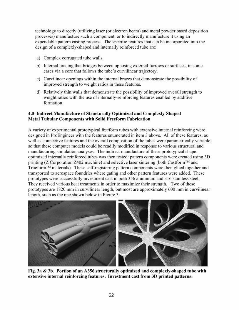
A variety of experimental prototypical freeform tubes with extensive internal reinforcing weredesigned in ProEngineer with the features enumerated in item 3 above. All of these features, aswell as connective features and the overall composition of the tubes were parametrically variableso that these computer models could be readily modified in response to various structural andmanufacturing simulation analyses. The indirect manufacture of these prototypical shapeoptimized internally reinforced tubes was then tested: pattern components were created using 3Dprinting (Z Corporation Z402 machine) and selective laser sintering (both Castform™ andTrueform™ materials). These self-registering pattern components were then glued together andtransported to aerospace foundries where gating and other pattern features were added. Theseprototypes were successfully investment cast in both 356 aluminum and 316 stainless steel.They received various heat treatments in order to maximize their strength. Two of theseprototypes are 1820 mm in curvilinear length, but most are approximately 600 mm in curvilinearlength, such as the one shown below in Figure 3.
Fig. 3a & 3b. Portion of an A356 structurally optimized and complexly-shaped tube withextensive internal reinforcing features. Investment cast from 3D printed patterns.
52

3
PowderedMetallurgy
Compaction
Deformation
Die Forming
Mass ConservingIndirect Tool-Dependent Processes
Manufacturing Processes for Structural Metal Components
Consolidation
Casting
Mass ReducingDirect Subtractive Processes
Electrical-DischargeMachining
ElectricallyReductive
CNC Turning
Axially-Constrained
Chip Making
MechanicallyReductive
ContinuousCutting
3D Formation
CNC Milling/Router
Surface-Constrained
2
Metal Solid Freeform Fabrication
Mass ConservingDirect Additive Processes
8
8
9
Expendable Mold
Ceramic Mold6 Bonded Sand Mold
Lost Foam Process
Patternless Sand Molds
Green Sand Molding
Shell-Mold Casting
Counter-GravityLow-Pressure Casting
No-Bake Resin Binder
Cold Box Resin Binder
7
Dry Sand Mold
V-Process (Vacuum)
7
Hybrid Ceramic/Sand Mold
Replicast Process
7
Cold or Warm
Hot Extrusion
Extrusion
Multiple &SequentialDie Rolling
Mass or IngotDeformation
Hot Rolling
Cold Rolling
StandardOptimized
Shapes
Tube Rolling
Bending
Sheet & Plate Def.
3
4
Tube Deformation
Hydro-Forming
Mandrel Swaging
Stretch Drawing
Rod/Bar Deformation
Cold Drawing
Hot Rotary Piercing
Tube & Bar Making
Swaging/Forging
Axially-Constrained Deformation
5
Mass Deformation
Hot Forging
Cold Forging
Swaging
Hot RollingStandard Plates
Sheet Deformation
Press Stamping
Stock Deformation
Tubes & Rods
Bending
Rolled Sections
Extrusions
Plates
Hydroformingof Tube Stock
Surface-Constrained Deformation
Reusable Mold
Spray Casting
Continuous Casting
Centrifugal Casting
Permanent Mold
Die Casting
Squeeze Casting
Surface -ConstrainedFormation
Axially-ConstrainedFormation
10
2D Formation
Continuous Cutting
Laser-Beam
Plasma-Arc
Electron-Beam
CNC Routering
Mechanical Cutting
Electron-Beam
Selective Laser Sintering
Metal 3D Printing
Laminated Object Manufacture
Laser Engineered Net Shapes
ChemicallyReductive
Electro-ChemicalMachining
1
Plaster Mold
Poured Ceramic Mold Casting
Investment Casting
PatternlessInvestment Casting
Cope & DragCeramic Mold
1. Electro-Chemical Machining (ECM) is used to machine forging dies from high-strength alloys and to form complex cavities in aerospace components. ECM technicallyhas the capacity to produce complex solid and tubular forms, but these would be limited in size by the work range of the machine set-up (typically for small parts) andexpensive: Part-specific tooling requires significant production volume or peformance criteria for the process to be economically viable .
2. Multi-Axis Mechanical CNC Milling can easily produce solid complexly-shaped metal parts, but complex tubes of any significant depth (beyond 2 times the depth of thebit - and chuck depending on opening size) cannot be produced unless they are longitudinal “halves” for making complex tubes as welded or assembled fabrications.
3. Standard tubular products can be hydroformed into either axially-constrained or complexly-shaped variable cross section tubes, the later being increasingly used in themaking of automobile chasis components. Equipment and tooling costs are high.
4. The use of Swaging to make variable section tubular components is inherently constrained by the need to remove the required mandrel after formation.
5. Swaging operations can utilze either all rotating dies (inherently axially constrained) or the combination of a stationary and a rotating die, which permit the formation ofnon-axial complexly-shaped solid parts, although this is less common.
6. All Ceramic Mold casting processes can produce complexly-shaped tubular components with internal (and external) features if necessary shell bridges and access holes areaccommodated, and especially if patterns are generated by Solid Freeform Fabrication technologies. However, Poured Ceramic and Plaster Mold processes are generally usedonly for small components, and designs for use with Patternless Investment Casting must accommodate the build volumes of SLS machines or assembly from SLS moldcomponents. The size capacity of Investment Casting has increased significantly in recent years and parts up to 60” or 80” are now successfully cast.
7. Bonded Sand Molds, Dry Sand Molds and the Replicast Process can be used to make complexly-shaped tubes with internal (and external) features, but these processes aresignificantly limited relative to Ceramic Mold Casting processes for two reasons: a). Pattern removal during mold making will not accommodate undercuts, and; b). Patternsare typically made using multiple-axis CNC machining/routering which would require subdividing the pattern into many components (discreet machining operations) toaccommodate significant internal complexity. Even then it would be difficult or impossible (depending on the design) to match the capability of Solid Freeform Fabrication.
8. Process can inherently make complexly-shaped tubes with internal features, but the design must accommodate the removal of unsintered or unbound powder, andproducts are very limited in size by the build volumes of various machines.
9. Research into the use of metal sheets for LOM is ongoing at Helisys, Inc. and The Warwick Manufacturing Group (UK). The process could make some complexly-shapedtubular designs, but its potential is very limited by the need to remove (de-cube) internal material.10. Permanent Mold Casting can produce complexly-shaped tubular parts if sand cores are used. This practice is fairly common.
Process with Capacity to Produce Complexly-Shaped Solid Components.
Process with Capacity to Produce Complexly-Shaped Tubular as well as Solid Components.
Process with Capacity to Produce Complexly-Shaped Tubes with Very Limited Internal Features.
Process with No Capacity to Produce Complexly-Shaped Solid or Tubular Components.
Process with Capacity to Produce Complexly-Shaped Tubes with Extensive Internal Features.
Fig. 4. Analytical Taxonomy: Manufacturing Complexly-Shaped Metal Components
53

5.0 Architectural Applications of Complexly-Shaped and Structurally OptimizedMetal Tubular Components
Complexly-shaped and structurally optimized metal tubular components are being designed bythe author’s architectural practice, Freeform Design & Manufacturing Research Studio, andmanufactured for use in full size architectural structures. The components shown in Figures 6and 7, for example, are prototypes for the conservatory structure shown in Figure 5. Thisstructure was designed as an assembly of discreet parametrically-variable components inProEngineer, and these components were in turn subdivided as required into self-registeringpattern components that will be manufactured both subtractively (CNC milled from high densityfoam) and additively using 3D printing. The pattern components will then be assembled andbonded together with foundry glue prior to being manufactured using a variety of hybrid sandand ceramic mold casting processes. The components were digitally analyzed both structurallyand in terms of castability (i.e. with MAGMA), and modified as required (i.e. per stress analysis,metal flow, and shrinkage). The model shown in Figure 5 was also designed as a kit of parts inProEngineer, and these parts were made with stereolithography, urethane castings made fromRTV tools and stereolithography patterns, and laminated object manufacture.
Fig. 5. Structural Model of a Conservatory Fig. 6. Component Patterns
Fig. 7a. A356 Prototype 7b. 316 Stainless prototypes, as cast and powder coated.
54
6.0 Notes on Biomimetic Structural Form
The notion of optimizing the strength-to-weight ratio and/or strength-to-material usage ratio of atubular structural component by optimizing its geometry (design) per anticipated product-specific service conditions can be considered a biomimetic approach to structural design enabledby solid freeform fabrication. This is because such an approach attempts to replicate some of thematerial efficiencies found in biologically generated structures. The author has defined twofundamental classes or approaches to biomimetic design:
1. The direct imitation of biologically generated structural efficiencies can be considered ascientific approach that includes:
replicating structural composition, which is always relative to other biological functionsand naturally occurring service conditions;
imitating material efficiency by minimizing and functionally varying or distributingmaterial usage
generally maximizing overall strength to weight ratio per natural precedent.
2. Aesthetically-driven or interpretive organic structural form, which is in part or whole anartistic approach to biomimetic design.
Design for commercial products (as opposed to performance specified, entirely non-aestheticproducts) involves the reconciliation of the scientific and artistic approaches to interpretingnatural structures. The balance can vary greatly, especially in architecture, and indeed this isreflected in the conservatory design shown here. However, the research introduced in this paper(e.g. per Figures 3a and 3b above) is focused solely on maximizing engineered “biomimetic”structural efficencies, not only for architectural purposes, but for a wide variety of small andlarge scale applications.
6.1 Cautionary Notes on Biomimetic Structural Form
1. Nature is generally highly efficient (i.e. economical). But, there is a distinction betweennatural economy and human economy. After satisfaction of service conditions (includingembedded safety factors), economic efficiency (cost) governs most commercial design (e.g.the retail warehouse is a high strength-to-weight ratio construct maximizing enclosed volumewhilst generally minimizing material usage – while a more efficient structure might bepossible, the cost of manufacturing the required components does not add sufficient value).
2. The higher the degree of material efficiency relative to function, the greater the extent towhich a structure might be considered “biomimetic,” regardless of its form.
3. The distinction between natural economy and human economy exists because nature hasmore sophisticated manufacturing (material forming) processes. SFF (especially inconjunction with FGM) and the emerging capacity to manufacture biologically (i.e. growcomponents and materials) are major steps in the ever-increasing human capacity to replicatenature. The commercialization of this increasing capacity is (as it always has been)constrained by cost benefit realities: the value added by new means of achievingconventional or previously impossible solutions must be sufficient to justify increased cost.
55
7.0 Concluding Discussion
Free-form tubular components with extensive internal reinforcing have been successfullyindirectly manufactured using a variety of expendable mold casting methods and expendablepatterns made with 3DP & SLS. These prototypes range up to 1820 millimeters in curvilinearlength. In addition, a wide variety of internal and external “biomimetic” geometricconfigurations have been developed. The quantification (measurement) of strength-to-weightratio improvements possible with these geometries is ongoing, and benchmark geometricconfigurations are being developed for experimental prototyping and comparative analysis usinga variety of direct metal processes. Powder based direct metal SFF processes that utilizesurrounding powder for support (SLS & 3DP/ProMetal) can presently best accommodatecomplex biomimetic tubular designs. The only major constraints on design with these processesare the need to remove powder from internal cavities and the limited (but improving) achievabletensile strengths.
Current research is focused on small scale applications, and assumes the capacity to manufacturecomplex internal features while also matching or exceeding the properties of wrought alloys.This assumption recognizes the fact that many of the possible benefits of structurally optimizedand complexly-shaped metal tubular components cannot be fully realized utilizing castingprocesses, even though expendable patterns with the required geometries can be produced usingSFF: the limitations of achievable material properties, especially tensile strength, even withappropriate heat treatments, can result in failure to fully capture the benefits of improvedgeometry, especially for service conditions requiring tensile performance.
Various laser or electron beam and metal powder based deposition methods, including LENS™and other proprietary processes, can presently best satisfy the material strength requirements ofthe designs. These processes, however, must address other significant issues and limitations inorder for the manufacture of structurally optimized and complexly shaped tubular components tobecome truly viable. These issues include:
1. Circumvention of the need for support structures in inaccessible areas via controlled multi-axis deposition.
2. Most path planning software for direct metal deposition processes cannot presentlyaccommodate complex geometric configurations. This is a very significant hurdle.
3. Accuracy and surface quality must be improved. Surface roughness can lead to fatiguecracking and catastrophic structural failure. Some service conditions will require CNCmilling of surfaces to eliminate this potential. Internal surfaces are therefore problematic andsuggest the need for hybrid metal deposition and subtractive processes. The path planningrequirements for such conditions are a significant hurdle.
4. Capturing the full benefits of biomimetic designs for freeform metal tubes is ultimatelydependent on realization of significant capacity to achieve functionally-graded materials –controlled local deposition of alloys via at least layer-based FGMs, but preferably voxel-based material specification and voxel-cluster material delivery.
1 The term Laser Engineered Net Shaping is used in Figures 1,2 and 4 to generically describe laser or electron beamand metal powder deposition processes.
56