
The Formwork Experts. Shifting trolley DF · The Formwork Experts. Shifting trolley DF Art. n°:...
13
© by Doka GmbH, A-3300 Amstetten 999216002 02/2020 en-GB - The Formwork Experts. Shifting trolley DF Art. n°: 586080000 | 1995 models onward Original Operating Instructions Please retain for future reference © by Doka GmbH, A-3300 Amstetten
Transcript of The Formwork Experts. Shifting trolley DF · The Formwork Experts. Shifting trolley DF Art. n°:...

© b
y D
oka
Gm
bH, A
-330
0 Am
stet
ten
999216002 02/2020en-GB
-
The Formwork Experts.
Shifting trolley DFArt. n°: 586080000 | 1995 models onward
Original Operating InstructionsPlease retain for future reference© by Doka GmbH, A-3300 Amstetten

2 999216002 - 02/2020
Original Operating Instructions Shifting trolley DF
Product presentationShifting trolley DF Art.n° 586080000
a ... 1440 mm b ... 1804 mm c ... 1540 mm to 3030 mm d ... 1340 mm e ... 1300 mm
Component overview
9216-200-01
a
b
d
ec
A Hand-pump leverB "Lift" buttonC Power supplyD 220 V/50 Hz electric motorE Hydraulic pumpF Non-return valveG Quick-acting coupling for attachable drive unitH Quick-acting coupling for attachable drive unitI Cylinder with isolation valveJ Manual lowering valveK Flow control valveL Overpressure valve

Original Operating Instructions Shifting trolley DF
3999216002 - 02/2020
Data on rating plate
Designation: Shifting trolley DFArt. n°: 586080000Dead weight: 566.0 kg (1247.8 lbs)Max. load: 1500 kg (3300 lbs)Year of manufacture: see rating plate
Intended use
The Shifting trolley DF is a lifting accessory. It is used for lifting and repositioning Dokaflex and Dokamatic tables (intended use).
Operator authorisation
The only persons allowed to operate the equipment are those who have been given sufficient instruction in how to use it, and who are familiar with all applicable oper-ating manuals and regulations. The client must obtain suitable evidence of the person-nel's ability to operate and handle this vehicle.
NOTICE ▪ Other use or use not in conformity with that
stated above is non-intended use and requires the prior written approval of the Doka company!
▪ It is forbidden to lift other manufacturers' formwork with it.
▪ In order to ensure that the equipment has been properly assembled, it must be inspected by a competent person before being used.
4 999216002 - 02/2020
Original Operating Instructions Shifting trolley DF
Maintenance & inspection ▪ Repairs may only be carried out by the manufac-
turer! ▪ Doka accepts no liability for products that have been
altered!
After taking delivery of the Shifting trolley DF
Damage in transit
The Shifting trolley DF is given thorough inspection and testing before being dispatched from the manufac-turer's factory. In order to make sure that no damage has occurred in transit, the Shifting trolley DF should be inspected thoroughly as soon as it is delivered. Any damage must be reported to the sender in writing. Until this notice of defect has been dealt with, the Shifting trolley DF may not be put into service.
Warranty conditions
The warranty shall lapse in the event of overloading or other improper use of the equipment.
Before starting up at a new site
▪ Lubricate with grease via the lubricating nipples pro-vided.
- on the guide mechanisms, 2x on the inside and 2x on the outside
- on the swivel casters (roller bearings and live ring)
▪ Lubricate the load chain and the deflection pulleys with lubricating grease.
Once a year, when lubricating the chain, inspect it care-fully for any signs of alteration and damage.
Before every use
➤Check for any signs of damage or visible deforma-tion.
At regular intervals
▪ Inspection of lifting accessories must be performed at regular intervals by an expert in conformity with national statutory provisions. Unless otherwise stipulated, such inspection must be carried out at least once a year.
Cleaning & maintenance
Clean the Shifting trolley DF whenever it has been made dirty, paying particular attention to: ▪ the hydraulic system ▪ the moving parts of the guide mechanisms ▪ the bearing surfaces of the supporting frame ▪ the swivel casters
Any deformed and damaged parts must be immediately replaced by an expert. For safety reasons, only genuine OEM spares may be used. ▪ Crack-free and notch-free welds. ▪ No deformation. ▪ Rating plate must be in place and clearly
legible

Original Operating Instructions Shifting trolley DF
5999216002 - 02/2020
Hydraulic system
Venting
Whenever the oil has been changed, or after repairs, the whole system can be bled via a bleeder screw on the cylinder.
Safety precautions
Depending on the version in question, the pressure lim-itation valve is pre-set to the maximum pressure of either 200 bar (grey hydraulic cylinder) or 250 bar (blue hydraulic cylinder).The adjusting screw of the pressure limitation valve is clearly marked. It is forbidden to tamper with this valve in any way whatever.The isolation valve is installed between the hydraulic hose and the hydraulic cylinder, and is set to a flow-rate of 20 l/min. It is forbidden to make any changes to this flow-rate.
Maintenance
Change the hydraulic oil every 2 years.Low-temperature hydraulic oil: Aero Shell Fluid 4 or oil of equal quality.Filling quantity of hydraulic oil: 6 l.
Lifting motor
Mounting the new lifting motor
The lifting motor is fastened onto the Shifting trolley DF with 2 hexagonal bolts M8x30 and hexagon nuts M8. Screw the hoses from the lifting motor onto the hydrau-lic lines of the Shifting trolley DF.
Putting the lifting motor into service
To prevent air penetrating into the hydraulic system after a new lifting motor has been connected, proceed as follows: ▪ Using the lever of the hand pump, extend the sup-
porting frame as far as its final position ▪ Actuate the manual lowering valve of the Shifting
trolley DF. After the supporting frame has been retracted 5 cm, switch on the electric motor as well, by pushing the button provided.
▪ After 30 seconds, release the manual lowering valve. The electric motor is now fully functional.
Storage
▪ Store lifting accessories in a dry and well ventilated place, protected from the weather and from all corro-sive substances.
CAUTIONHydraulic oil is harmful to the environment!➤For this reason, always properly seal any
leaks immediately!➤ Intercept any leaking hydraulic oil and dis-
pose of it in accordance with the applicable regulations!

6 999216002 - 02/2020
Original Operating Instructions Shifting trolley DF
Height adjustment
a ... height Stacking frames
without stacking frames
Height ranges incl. distribution beams
with Stacking frame DF
Art.n° 586079000
a ... 750 mm b ... 1340 mm c ... 1300 mm Weight: 82 kg
Height ranges incl. distribution beams
Note:If Stacking frames DF are used, these must each be bolted on using 4 hexagonal bolts M 12x40 (supplied with the stacking frame)
with Alu stacking frame DM 2.25m
Art.n° 586238000
a ... 2250 mm b ... 1340 mm c ... 1873 mm d ... 1010 mm e ... 1285 mm Weight: 59.2 kg
Height ranges incl. distribution beams
A Shifting trolley DFB Stacking frame DFC Distribution beams (Doka beams H20 2.65m)D Brace stirrup 8
NOTICEPoints to remember with unsymmetrical tables:"Central positioning" means "central" in terms of the load centre.Take particular care with unsymmetrical tables (edge tables, tables with stop-ends).
h min. [cm] h max. [cm]174.0 323.0
Max. load per Shifting trolley DF without stacking frames, where the load is applied centrally:1500 kg
9216-206-01
B
A
C
D
h
a
b
ca
Number of Stacking frames DF h min. [cm] h max. [cm]
1 249.0 398.02 324.0 473.03 399.0 548.0
Max. load per Shifting trolley DF with Stacking frame DF, where the load is applied centrally: ▪ with one Stacking frame DF: 1418 kg ▪ with two Stacking frames DF: 1336 kg ▪ with three Stacking frames DF: 1254 kg
h min. [cm] h max. [cm]399.0 548.0
Max. load per Shifting trolley DF with one Alu stacking frame DM 2.25m where the load is applied centrally: 1440 kg
b
c
da
e
Original Operating Instructions Shifting trolley DF
7999216002 - 02/2020
Repositioning operation
Positioning under the tableform
General
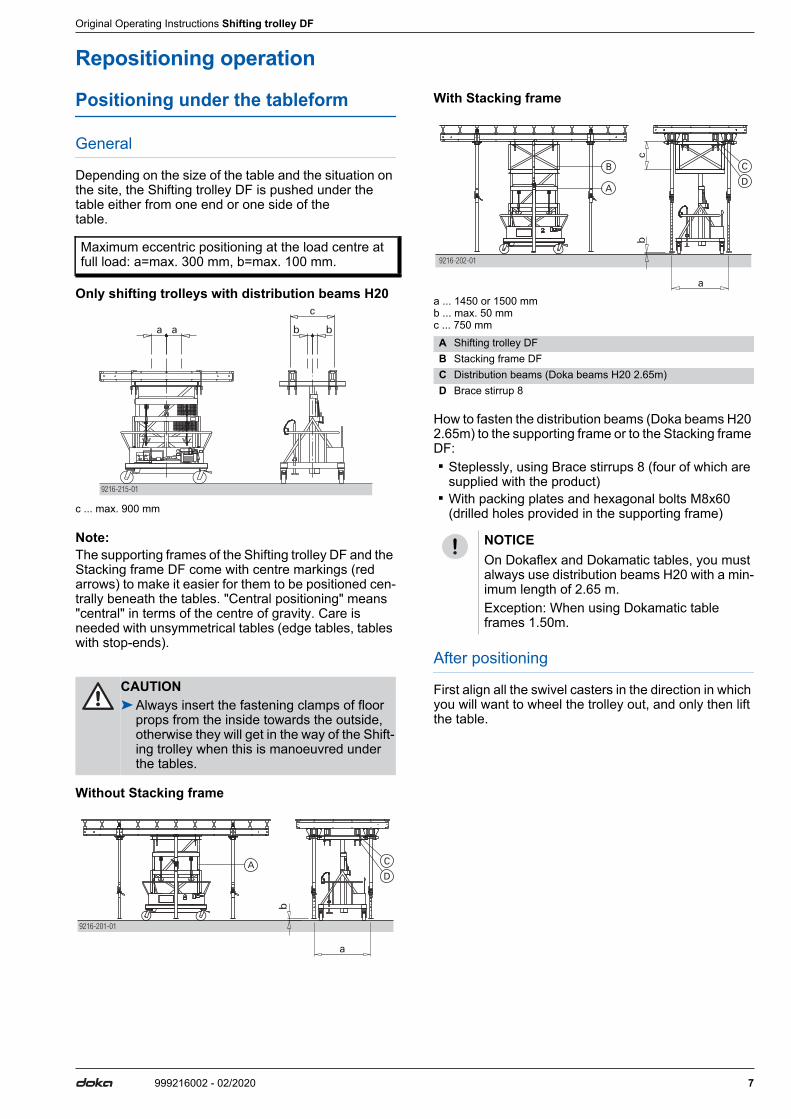
Depending on the size of the table and the situation on the site, the Shifting trolley DF is pushed under the table either from one end or one side of the table.
Only shifting trolleys with distribution beams H20
c ... max. 900 mm
Note:The supporting frames of the Shifting trolley DF and the Stacking frame DF come with centre markings (red arrows) to make it easier for them to be positioned cen-trally beneath the tables. "Central positioning" means "central" in terms of the centre of gravity. Care is needed with unsymmetrical tables (edge tables, tables with stop-ends).
Without Stacking frame
With Stacking frame
a ... 1450 or 1500 mm b ... max. 50 mm c ... 750 mm
How to fasten the distribution beams (Doka beams H20 2.65m) to the supporting frame or to the Stacking frame DF: ▪ Steplessly, using Brace stirrups 8 (four of which are
supplied with the product) ▪ With packing plates and hexagonal bolts M8x60
(drilled holes provided in the supporting frame)
After positioning
First align all the swivel casters in the direction in which you will want to wheel the trolley out, and only then lift the table.
Maximum eccentric positioning at the load centre at full load: a=max. 300 mm, b=max. 100 mm.
CAUTION➤Always insert the fastening clamps of floor
props from the inside towards the outside, otherwise they will get in the way of the Shift-ing trolley when this is manoeuvred under the tables.
a a b b
9216-215-01
c
C
9216-201-01
DA
A Shifting trolley DFB Stacking frame DFC Distribution beams (Doka beams H20 2.65m)D Brace stirrup 8
NOTICEOn Dokaflex and Dokamatic tables, you must always use distribution beams H20 with a min-imum length of 2.65 m.Exception: When using Dokamatic table frames 1.50m.
9216-202-01
C
DA
B

8 999216002 - 02/2020
Original Operating Instructions Shifting trolley DF
Shifting
The Shifting trolley DF is fitted with 4 heavy-duty swivel casters of ø250 mm. Two of these wheels are equipped with a fixing brake. Setting down and positioning the
tableform
➤Every time after you shift / travel the Shifting trolley DF, check:
Lifting and lowering (with/without load)
There are 2 ways of hydraulically lifting and lowering: ▪ with the hand-pump ▪ with the electric lifting motorBefore lifting, check that the positioning is correct.
Lifting manually
▪ Work the pump lever- Lifting speed: 1 cm per up-and-down stroke- Maximum lifting height: 150.0 cm- Overload protection provided by built-in pres-
sure-limitation valve.
Lifting by motor
▪ Press the Start button- Electrical connection: 220 V/50 Hz- Lifting speed: 1 m/min- Maximum lifting height: 150.0 cm- Overload protection provided by built-in pres-
sure-limitation valve.
Lower
▪ Open the lowering valve- Regulate the speed of lowering on the valve
NOTICEImportant points to remember when wheel-ing load-bearing towers: ▪ Only use the Shifting trolley DF for Dokaflex
and Dokamatic tables. ▪ Ground clearance of the props max. 5 cm. ▪ Do not shift tables with the hydraulic mech-
anism extended too far (more than 5 cm). ▪ Travelling only permitted up to a gradient of
5 %.- Max. load-bearing capacity is 15 kN on
a gradient of up to 3%- Max. load-bearing capacity is 9 kN on a
gradient of up to 5%. ▪ The floor must be stable, firm and suffi-
ciently smooth (e.g. concrete). ▪ Particular care is needed with:
- Height offsets- Steps- Break-throughs- Strong wind
▪ Keep the travel route clean and free of any obstacles.
▪ Either bridge any openings in the floor with sufficiently strong planking/boards secured so that they cannot slip away to either side, or close off openings with sufficiently strong side railings!
▪ "Passenger transportation" is forbidden! ▪ Max. length of table 5 m. Extra-long tables
must be travelled using 2 Shifting trolleys DF.
▪ It is forbidden to use any other mechanical assistance for the travelling operation! Exception: Attachable drive unit DF
▪ Max. speed 4 km/h (walking pace) ▪ For longer breaks between operations, or
when the Shifting trolley DF is permanently parked, it must NOT be carrying any form-work.
▪ After wheeling the Shifting trolley DF to its new position, fix it so that it cannot be moved accidentally.(apply the fixing brakes, wedge the wheels with chocks, etc.).
▪ It is forbidden to travel the Shifting trolley DF if any electric cables are still attached.
▪ Crane transport is only allowed using the lifting-bracket provided for this purpose (marked red).
A Crane suspension tackle (1-part)B Lifting-bracket
9216-204-01
A
B
Follow the directions in the "Attachable drive unit DF" Operating Instructions!
▪ that the fastening clamps of the floor props are in the right position
▪ and that the floor props are firmly clamped in the Dokamatic swivel-heads.
A Pump leverB Lowering valveC Pushbutton
A
B C
9216-205-01

Original Operating Instructions Shifting trolley DF
9999216002 - 02/2020
Lining-and-levelling
With the Shifting trolley DF, Dokaflex and Dokamatic tables can be exactly positioned, and lined-and-lev-elled. The positioning lever - supplied along with the trol-ley - is used for exactly aligning the heavy-duty swivel casters in the desired direction of travel.➤ Insert the positioning lever into the basic frame as far
as it will go.➤Push down the positioning lever.
This lifts the wheel slightly off the ground, making it easy to align the wheel in the desired direction of travel.
➤Repeat this procedure on all 4 wheels.➤Then wheel the table exactly into position.➤Lift the tables up to the desired height and fine-adjust
the floor props accordingly.

10 999216002 - 02/2020
Original Operating Instructions Shifting trolley DF
Extensions for Shifting trolley DF
Art.n° 5860150000
a ... 1284 mm b ... 580 mm c ... 204 mm d ... 500 mm e ... 150 mm f ... 1174 mm to 1866 mm g ... 253 mm h ... 200 mm i ... 398 mm
Practical example
with Stacking frame DF
with Alu stacking frame DM 2.25m
h ... 5.80 m to max. 7.30 m
a ... min. 500 mm
NOTICEAt a table height of 5.80 to 7.30 m, the Exten-sions for Shifting trolley DF must be mounted on Shifting trolley DF and extended!
f h
a
i
g
eb c d
9216-207-01
I
H
G
E
F
D
C
B
A
J
h
A Extensions for Shifting trolley DFB Shifting trolley DFC Stacking frame DFD Floor prop Eurex 20 550E Brace stirrup 8F Doka beam H20 (distribution beam)G Dokamatic table frame 1.50mH Diagonal cross 18,250I Scaffold connection (complete)J Dokamatic table 2.50x5.00mK Alu stacking frame DM 2.25m
➤When using Dokamatic table frames 1.50m, ensure that the H20 distribution beams are sufficiently long.
9216-213-01
I
H
G
E
F
D
K
B
A
J
h
H
9216-214-01
F
a a

Original Operating Instructions Shifting trolley DF
11999216002 - 02/2020
Assembly
➤Fix the Shifting trolley DF so that it cannot be moved accidentally.(apply the fixing brakes, wedge the wheels with chocks, etc.).
➤Push the "Extensions for Shifting trolley DF" (A) under the Shifting trolley DF.
➤Extend the short "Extension" (F) by at least 50 mm.➤The short "Extension" (F) is on the same side as the
drive unit (K) .
a ... 50 mm➤Fasten with hexagonal bolts M16x45 (G) , hexagon
nuts M16 (H) and washers 17 (I) .
x ... playIf there is too much play between the U-profiles of the Shifting trolley DF (B) and the "Extensions" (A) , the distance plates (C) must also be screwed on.
Positioning under the tableform
➤The "Extensions" must be mounted to the Shifting trolley DF, with both extensions retracted (i.e. pushed in).
➤Wheel the Shifting trolley DF under the Dokaflex or Dokamatic table, and position it.
Extending the "Extensions"
➤Lift the Safety clip (D) .
➤Pull out the wheel as far as it will go.The Safety clip must snap into place.
Retracting the "Extensions"
➤Lift the Safety clip (D) .➤Push the wheel back in as far as it will go.
The Safety clip must snap into place.
A Extensions for Shifting trolley DFB Shifting trolley DFC Distance plateD Safety clipE Extension 1 (complete)F Extension 2 (complete) - short sideG Hexagonal bolt M16x45H Hexagon nut M16I Washer 17K Drive unit for Shifting trolley DF
All 4 screws must be firmly tightened.
G
DC
HI
E F
A
9216-211-01
a
B
K
F
9216-212-01
x
C
A
GHI
B
CAUTION➤Always insert the fastening clamps of floor
props from the inside towards the outside, otherwise they will get in the way of the Shift-ing trolley when this is manoeuvred under the tables.
D
9216-210-01
D

12 999216002 - 02/2020
Original Operating Instructions Shifting trolley DF
Troubleshooting
Load not being lifted
Possible causes: ▪ Load too heavy (> 1500 kg, including Stacking
frame) ▪ Not enough hydraulic oil ▪ Mechanical guide mechanisms are damaged or are
tending to get jammed ▪ Hydraulic pump is faulty ▪ Overpressure valve is wrongly adjusted or faulty ▪ Manual lowering valve is leaking (e.g. due to con-
taminated oil)
Load not being completely lifted
Possible cause: ▪ Not enough hydraulic oil
The load is being lowered of its own accord
Possible causes: ▪ Load too heavy (> 1500 kg, including Stacking
frame) ▪ Hydraulic tubing is leaking ▪ Overpressure valve is wrongly adjusted or faulty ▪ Non-return valve on electrical hydraulic pump is
leaking ▪ Manual lowering valve is leaking (e.g. due to con-
taminated oil) ▪ Hand-pump valves are leaking
The load cannot be lowered
Possible causes: ▪ Low ambient temperatures (hydraulic oil is too vis-
cous) ▪ Flow control valve is blocked (e.g. due to contami-
nated oil) ▪ Manual lowering valve is defective ▪ Isolation valve is defective
The load is being lifted jerkily and/or "bounces"
Possible causes: ▪ Trapped air in the hydraulic tubing and/or the
hydraulic cylinder ▪ Mechanical guide mechanisms are damaged or are
tending to get jammed
The hydraulic lines of the Attachable drive unit DF cannot be connected or disconnected (quick-acting coupling)
Possible causes: ▪ High pressure in the hydraulic system of the Shifting
trolley DF ▪ High pressure in the hydraulic system of the Attach-
able drive unit DF ▪ Residual soiling on coupling components ▪ Quick-acting coupling is faulty
Electrical hydraulic pump not pumping
First try out whether it is possible to use the pump in manual mode. If it is, then there are the followingPossible causes: ▪ Problems with the electric power supply ▪ Not enough hydraulic oil ▪ The ON button is faulty ▪ The electric motor is faulty (e.g. capacitor) ▪ Mechanical breakage (gear pump, coupling) ▪ Damaged pump seals
Hydraulic hand-pump is not functioning
Possible causes: ▪ Not enough hydraulic oil ▪ Breakage in the mechanical drive system (levers,
articulated joints, pistons) ▪ Damaged or worn-out seals in the pump system ▪ Mechanical breakage (gear pump, coupling) ▪ Pump valves leaking
Original Operating Instructions Shifting trolley DF
13999216002 - 02/2020
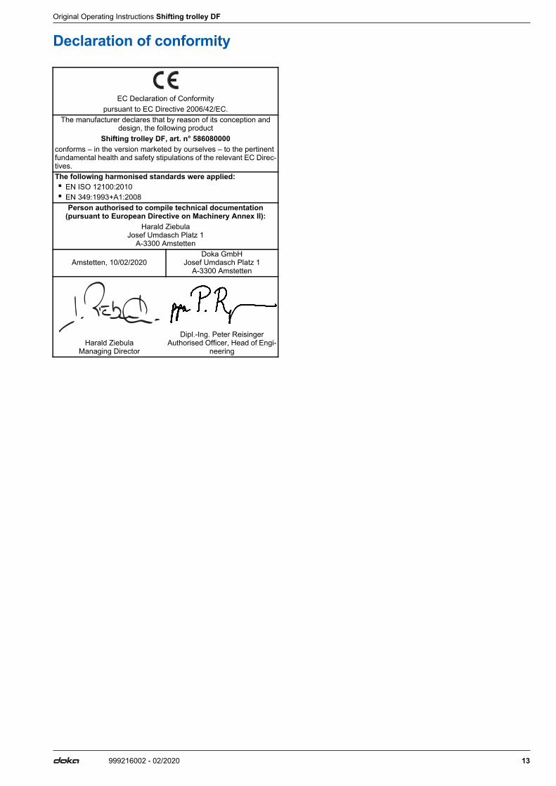
Declaration of conformity
EC Declaration of Conformitypursuant to EC Directive 2006/42/EC.
The manufacturer declares that by reason of its conception and design, the following product
Shifting trolley DF, art. n° 586080000conforms – in the version marketed by ourselves – to the pertinent fundamental health and safety stipulations of the relevant EC Direc-tives.The following harmonised standards were applied: ▪ EN ISO 12100:2010 ▪ EN 349:1993+A1:2008
Person authorised to compile technical documentation (pursuant to European Directive on Machinery Annex II):
Harald ZiebulaJosef Umdasch Platz 1
A-3300 Amstetten
Amstetten, 10/02/2020Doka GmbH
Josef Umdasch Platz 1A-3300 Amstetten
Harald ZiebulaManaging Director
Dipl.-Ing. Peter ReisingerAuthorised Officer, Head of Engi-
neering