The following catalog has gaps in its page numbers, or ...n0nas/manuals/onan/904-0211 Onan... ·...
48
The following catalog has gaps in its page numbers, or doesn’t have any numbers. We have chosen to leave the page numbering in the order that Acrobat assigns it.
Transcript of The following catalog has gaps in its page numbers, or ...n0nas/manuals/onan/904-0211 Onan... ·...

The following cataloghas gaps in its pagenumbers, or doesn’thave any numbers.We have chosen to
leave the pagenumbering in theorder that Acrobat
assigns it.

CIRCumminsPower
9Systems
i
Parts Catalog
VT28
VTA28
PMG Generator Set I

●b
.
●
.
*
●
Important Safety Precautions
Read and observe these safety precautions when usingor working on electric generators, engines and relatedequipment. Also read and follow the literature providedwith the equipment.
Proper operation and maintenance are critical to perfor-mance and safety. Electricity, fuel, exhaust, moving partsand batteries present hazards that can cause severepersonal injury or death.
FUEL, ENGINE OIL, AND FUMES AREFLAMMABLE AND TOXICFire, explosion, and personal injury can result from im-proper practices.
Used engine oil, and benzene and lead, found insome gasoline, have been identified by governmentagencies as causing cancer or reproductive toxicity.When checking, draining or adding fuel or oil, do notingest, breathe the fumes, or contact gasoline orused oil.
Do not fill tanks with engine running. Do not smokearound the area. Wipe up oil or fuel spills. Do notleave rags in engine compartment or on equipment.Keep this and surrounding area clean.
Inspect fuel system before each operation and peri-odically while running.
Equip fuel supply with a positive fuel shutoff.
Do not store or transport equipment with fuel in tank.
Keep an ABC-rated fire extinguisher available nearequipment and adjacent areas for use on all types offires except alcohol.
Unless provided with equipment or noted otherwisein installation manual, fuel lines must be copper orsteel, secured, free of leaks and separated orshielded from electrical wiring.
Use approved, non-conductive flexible fuel hose forfuel conneti.ons. Do not use copper tubing as a flex-ible connection. It will work-harden and break.
EXHAUST GAS IS DEADLY
Engine exhaust contains carbon monoxide (CO),an odorless, invisible, poisonous gas. Learn thesymptoms of CO poisoning.
Never sleep in a vessel, vehicle, or room with a gen-set or engine running unless the area is equippedwith an operating CO detector with an audiblealarm.
Each time the engine or genset is started, or at leastevery day, thoroughly inspect the exhaust system.Shut down the unit and repair leaks immediately.
. Warning: Engine exhaust is known to the State ofCalifornia to cause cancer, birth defects and otherreproductive harm.
Make sure exhaust is properly ventilated.
●
●
●
●
●
●
Vessel bilge must have an operating powerexhaust.
Vehicle exhaust system must extend beyond ve-hicle perimeter and not near windows, doors orvents.
Do not use engine or genset cooling air to heat anarea.
Do not operate engine/genset in enclosed areawithout ample fresh air ventilation.
Expel exhaust away from enclosed, sheltered, oroccupied areas.
Make sure exhaust system components are se-curely fastened and not warped.
MOVING PARTS CAN CAUSE SEVEREPERSONAL INJURY OR DEATH
●
●
●
●
●
Do not remove any guards or covers with the equip-ment running.
Keep hands, clothing, hair, and jewelry away frommoving parts.
Before performing any maintenance, disconnectbattery (negative [-] cable first) to prevent acciden-tal starting.
Make sure fasteners and joints are secure. Tghtensupports and clamps, keep guards in position overfans, drive belts, etc.
If adjustments must be made while equipment isrunnjng, use extreme caution around hot manifoldsand moving parts, etc. Wear safety glasses and pro-tective clothing.
BAITERY GAS IS EXPLOSIVE
●
●
●
Wear safety glasses and do not smoke while servic-ing batteries.
Always disconnect battery negative (-) lead firstand reconnect it last. Make sure you connect batterycorrectly. A direct short across battery terminals cancause an explosion. Do not smoke while servicingbatteries. Hydrogen gas given off during charging isexplosive.
Do not disconnector connect battery cables if fuelvapors are present. Ventilate the area thoroughly.
GSP-IIofz

DO NOT OPERATE IN FLAMMABLE ANDEXPLOSIVE ENVIRONMENTSFlammable vapor can be ignited by equipment operationor cause a diesel engine to overspeed and become diffi-cult to stop, resulting in possible fire, explosion, severepersonal injury and death. Do not operate diesel equip-ment where a flammable vapor environment can becreated by fuel spill, leak, etc., unless equipped withan automatic safety device to block the air intake andstop the engine.
HOT COOLANT CAN CAUSE SEVEREPERSONAL INJURY
● Hot coolant is under pressure. Do not loosen thecoolant pressure cap while the engine is hot. Let theengine cool before opening the pressure cap.
ELECTRICAL SHOCK CAN CAUSE SEVEREPERSONAL INJURY OR DEATH
If the cabinet must be opened for any reason:
1.
2.
3.
Move genset operation switch or Stop/Auto/I-landcrank switch (whichever applies) to Stop.
Disconnect genset batteries (negative [-] leadfirst).
Remove AC Dower to automatic transferswitch. If instr&tions require otherwise, useextreme caution due to shock hazard.
MEDIUM VOLTAGE GENERATOR SETS(601V TO 15kV)
●
●
●
●
●
●
Do not service control panel or engine with unit run-ning. High voltages are present. Work that must bedone while unit is running should be done only byqualified service personnel.
Do not connect the generator set to the public utilityor to any other electrical power system. Electrocu-tion can occur at a remote site where line or equip-ment repairs are being made. An approved transferswitch must be used if more than one power sourceis connected.
Disconnect starting battery (negative [-] cable first)before removing protective shields or touching elec-trical equipment. Use insulative mats placed on drywood platforms. Do not wear jewelry, damp clothingor allow skin surface to be damp when handlingelectrical equipment.
Use insulated tools. Do not tamper with interlocks.
Follow ail applicable state and local electricalcodes. Have all electrical installations performed bya qualified licensed electrician. Tag open switchesto avoid accidental closure.
With transfer switches, keep cabinet closed andlocked. Only authorized personnel should havecabinet or operational keys. Due to serious shockhazard from high voltages within cabinet, all serviceand adjustments must be performed by an electri-cian or authorized semice representative.
Medium voltage acts differently than low voltage.Special equipment and training are required to workon or around medium voltage equipment. Operationand maintenance must be done only by personstrained and qualified to work on such devices. im-proper use or procedures will result in severe per-sonal injury or death.
Do not work on energized equipment. Unauthorizedpersonnel must not be permfied near energizedequipment. Induced voltage remains even afterequipment is disconnected from the power source.Plan maintenance with authorized personnel soequipment can be de-energized and safelygrounded.
GENERAL SAFETY PRECAUTIONS●
●
●
●
●
Do not work on equipment when mentally or physi-cally fatigued or after consuming alcohol or drugs.
Carefully follow all applicable local, state and feder-al codes.
Never step on equipment (as when entering or leav-ing the engine compartment). It can stress andbreak unit components, possibly resulting in dan-gerous operating conditions from leaking fuel, leak-ing exhaust fumes, etc.
Keep equipment and area clean. Oil, grease, dirt, orstowed gear can cause fire or damage equipmentby restricting airflow.
Equipment owners and operators are solely re-sponsible for operating equipment safely. Contactyour authorized Onan/Cummins dealer or distribu-tor for more information.
KEEP THIS DOCUMENT NEAR EQUIPMENT FOREASY REFERENCE.
,
GSP-12of2

Index
.
Adapter, Generator . . . . . . . . . . . 43.4s.47Alarm Module . . . . . . . . . . . . . . . . . . . . . ...68Alternator . . . . . . . . . . . . . . . . . . . . . . . . . . 5Ammeter -AC...... . . . . . . . . . . . ...55.57Ammeter -DC...... . . . . . . . . . . . ...59.61
Belt, Drive . . . . . . . . . . . . . . . . . . . . . ...5Board, Autostart . . . . . . . . . . . . . . ...66.67Board, LED Lights . . . . . . . . . . . . . . . . . 55
Cap, Radiator . . . . . . . . . . . . . . . . . . . . . . 5Cleaner, Air -Heavy Duty . . . . . . . . ..7Cleaner, Air-Indoor . . . . . . . . . . . . ...7Cleaner, Air-Outdoor . . . . . . . . . . . ...7Contactor, Heater . . . . . . . . . . . . . . . . . . 9Control, Engine . . . . . . . . . . . . . . ...59.61Control, Generator Set...... . . . . ...53Control, Generator . . . . . . . . . . . . . . 55.57Control, Overspeed 66,67Controller, Governor.::::::::::: : 66,67
Disk, Orive . . . . . . . . . . . . . . . . . . 43,45,47
Element, Air Cleaner . . . . . . . . . . . . . . . . 7Element, Oil Filter . . . . . . . . . . . . . . . . 5Exciter, Permament Magnet . . . . . . . . . . 48
Filter, Fuel . . . . . . . . . . . . . . . . . . . . . . . 7Filter, Oil . . . . . . . . . . . . . . . . . . . . . . . . 7Filter, Water . . . . . . . . . . . . . . . . . . . . . 5Gauge, Pressure -Oil..... . . . . . . . 59,61Gauge, Temperature . . . . . . . . . . . . . . 59,61Generators . . . . . . . . . . . . . . . . . . . . . . . . . 35Guard, 8elt . . . . . . . . . . . . . . . . . . . . . . . . 5
Harness, Engine . . . . . . . . . . . . . . . . . . . . “/Harness, Engine Control . . . . . . . . . 59,61Harness, Generator Control . . . . . . 63,65Heater, Generator . . . . . . . . . . . . . 37,39,41Heater, Water . . . . . . . . . . . . . . . . . . . . . . 9Horn, Electrical . . . . . . . . . . . . . . . . ...68
Indicator, Air Service . . . . . . . . . . ...7
Meter, Hour . . . . . . . . . . . . . . . . . . . . .59,61
Regulator, Voltage . . . . . . . . . . . 37,39,4IRelay . . . . . . . . . . . . . . . . . . . . . . . . ...66.67Rotor, Exciter . . . . . . . . . . . . ...43.45 ,47Rotor, Generator . . . . . . . . . . . . . 43.45.47
Sender, Pressure-Oil . . . . . . . . . . ...5Sender, Temperature . . . . . . . . . . . . . ...5Starter . . . . . . . . . . . . . . . . . . . . . . . . . . . . 5Stator, Exciter . . . . . . . . . . . . . . 37,39,41Stator, Generator . . . . . . . . . . . . 37,39,41Switch, Heater Control . . . . . . . . . . . . . 21Switch, Level - Coolant . . . . . . . . . . . . 5Switch, Magnetic -Starter . . . . . . ...5Switch, Pressure - Oil...... . . . . . . . . 7Switch, Selector . . . . . . . . . . . . . . . . 55,57Switch, Temperature . . . . . . . . . . . . . . . . 7
Tachometer . . . . . . . . . . . . . . . . . . . ...59.61Transducer, Temperature - Water 5Transducer, Watt . . . . . . . . . . . . . . . . . . . 67Transducer, Pressure - Oil 5Transformer, Current . . . . . . . . . . . . . . . 53
Voltmeter . . . . . . . . . . . . . . . . . 55,57,59,61
Wattmeter . . . . . . . . . . . . . . . . . . . . . . . 55,57

Introduction
●This Parts Catalog applies to the Generator Sets Listed below. The illustrations arearranged in groups of related items, and each part or assembly is identified by aReference Number. All parts illustrated are typical, and unless otherwise mentioned
i
in the description column the parts are interchangeable between models. Dual Part No.may be applicable; CPS are Cummins Power Systems assigned Part Numbers and CEC are theCummins Engine Company asigned Part Numbers.
These typical
w
illustrations are subject to change and reflect only the latest replace-ment parts arrangement. The Right and Left sides of the Generator Set are determinedby FACING the FRONT of the Set (Engine Radiator End)
Set Data Table
ENGINE ID. No. GEN SET 10 No. RPM RATING BATTERY VOLTAGE
Note 1 Note 2.VT28-G*# xxxVT~ - ~— 1800 RPM/ 1500 RPM 24 VDC
VTA28-G*# — 1800 RpM/ 1500 RPM 24 VDC
Note:l * - Letter S for Standby, Letter C for Continuous Duty applicationsNote:l # - Number 1 thru 9 used to denote size varations.Note:2 x - Numbers used to denote kW ratings: eg: 230 means 230,000 watt set.Note:2 @ - Number used to denote size varations.NOTE:2 s - Numbers and a letter used to provide configuration identification.
Electrical Data Table
vLOW Y
190/110208/120220/127230/133240/139
190/110200/115208/120
TAGEHIGH Y
380/219416/220440/254460/266480/277
380/219400/231416/240
HERTZ
6060606060
505050
WIRE
1212121212
PHASE
33333
NOTES
Engine Replacement Parts
The External Engine Components added or modified during the Generator Set Assembly andmost General Maintance Items are identified in this Parts Catalog. For Internal EngineParts and Components not covered herein; refer to the applicable Cummins Engine G DriveParts Catalog.
.
2

General Information
.
●
For parts or service, contact the distributor from whom you purchased
this equipment or refer to the nearest Authorized Cummins Distributor.
To avoid errors or delays in filling your parts order, always give thefull MODEL, SERIAL and ID No. from the nameplate.
For handy reference, insert “YOUR*nameplate information is the spaces below.
c AC Generator SetModel
kw kva Pf phase
voltaae amps
duty overload
rpm hz
class of insulation pmq voltage
field amp max field voltaqe max
qenerator model no.
voltaqe requlator model no.
ID no.
qenerator set serial no.
BS5000 NEMA
‘3
-..
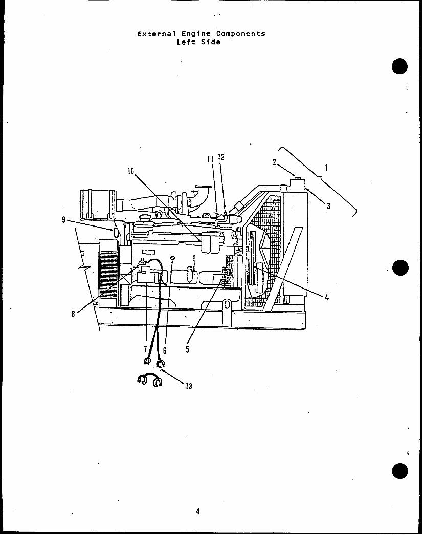
External Engine ComponentsLeft Side
.
9
\4
“

CPS CECPART NO. PART NO.
130-0523130-2981130-3395
3
130-3320-033050215130-3320-04 3050216130-3320-04 3050216130-3320-05 3050330130-3320-04 3050216130-3320-05 30S0330
45
● 67
8
1:
130-3320-04 3050216130-3320-04 30!50216130-3320-05 3050330130-3320-05 3050330130-3320-05 2050330511-0165 3001600
191-1846-01 3016627130-3317-01 201986S11-0163 3040283302-1853 3015237
3021038191-1588307-2621-02 3050692122-0526 3313283
33182013318319
302-1854 301S238309-0570 3034866
416-0636416-0473416-0639337-2401-06 3058410
QTYUSED
Ref
:1
111
:1
:1113
1121
:12
2211
. .
External Engine ComponentsLeft Side
PARTDESCRIPTION
Cooling System - Radiator (Select components as required)Cap, Radiator (Select as applicable)
7 PSI (For 2“ Fill Tube)7 PSI (For 3“ Fill Tubej10 PSI (For 2“ Fill Tube)
Radiator (Includes Front Guards, Excludes Cap)Standard Cooling 40”C/100”F
VT28 with Dry or Wet ManifoldVTA28-1 with Ory or Wet ManifoldVTA28-2 with Dry ManifoldVTA28-2 with Wet ManifoldVTA28-3 with Ory ManifoldVTA28-3 with Wet Manifold
Hi Ambient Cooling 50”C/125°FVT28 with Dry and Wet ManifoldVTA28-1 with Dry ManifoldVTA28-1 with wet ManifoldVTA28-2 with Ory or Wet manifoldVTA28-3 with Ory Manifold
Belt, Orive (Fan)Alternator Charging Components
Alternator (35 Amp, 24 VOC)Pulley, OriveBelt, Drive
Transducer (Sender), Pressure - OilStarter, 24 VDC
StandardHeavy Outy
Switch, MagneticFilter, Oil - Bypaas [LF777]
*Filter, Water - W/Corosion Inhibiting Chemical DCA4Service for 60-90 Gal Cooling Systems [WF2072]Pre-Charging for 60-90 Gal Cooling Systems [WF2076]
Transducer (Sender), Temperature - Engine CoolantSwitch, Tamperarure - Engine CoolantCables & Leads
Cable, 8attery (55” Lg)Cable, %attery - JumperCable, Battery (60” Lg)Lead, Electrical
* NOTE: Replacement cartridges recommend and should be used in lieu of the OriginalEngine Factory Installed Item which contains a Pre-Charge amount of DCA or0CA4 Chemical. Replacement with Pre-charge Cartridge may overload the CoolingSystem and cause problems or failure of the Set.
[ ] Numbers in Brackets are F’
.
aetwood Inc. Identification.
5

●
External Engine ComponentsRight Side
●☞✎
12
9 10 I
4
5
7 6
6
,

b
REFNO.
.
1234
5678
1:
CPSPART NO.
140-2226140-1260140-1545
140-2225
140-1647140-1649140-1650338-2334
CECPART NO.
178957
152007
30216443022209
30216453022209
300095830132103013211305302933132’79299202
309-0579-03 3046031309-0570 3034866
309-0565-01 3034864309-0566 3034863
QTYUSED
222
22
22
222132
;
11
,
External Engine ComponentsRight Side
PARTDESCRIPTION
Indicator, Air Restriction (Includes Fitting)Fitting, Male - HexCap, Air CleanerAir Cleaner (Select components as required)
Indoor ApplicationIncludes ElementElement [AF928M]
Outdoor ApplicationIncludes ElementElement [AF928M]
Heavy Duty ApplicationIncludes ElementsElement, Primary
[AF891M]
Element, Secondary AF890]Harness, Wiring - EngineFilter, Oil [LF670]Filter, Fuel [FF202]Switch, Low Coolant LevelSwitch, Temperature - Engine CoolantSwitch, Pressure - Oil
Standard, 3 Wire HarneesPre-Alarm System, 4 Wire Harness
1

21
/
20
,
Heater - Engine Coolant
116
((“Y
—6
9
.
-15

,
Heater - Engine Coolant
s
REFNO.
●
;3456~.
1:
●15
CPS CECPART NO. PART NO.
501-0537-03 AS4032SS502-1043-01 68139503-1603 43828A503-1602 3027706502-1046 S932B
3002718130-3339 3056677130-3340 3056679
333-0413-08 3063473333-0389-02 3056182333-0389-04 3056184333-0389-06 3053979
800-0222 S114850-0101 S600402-0608 3035083402-0609 3035084
504-000330599033059904
130-3189 3056255
800-0210 S103D850-0103 S604871-0028 S254
16
309-0567-01 3056188309-0567-02 3056189
2021 333-0390
PARTDESCRIPTION
Hose Assembly - Oil PressureElbow, Pipe - Male, 90 DEGClamp, HoseHose, RubberCoupling, HoseCoupling, Hose - ElbowTube, WaterTube, WaterHeater, Electrical - Engine Coolant (Includes Thermostat,
Oil Pressure Switch, Drain Cock and Mounting Nuts)4000 Watt, 208 VAC4000 Watt, 240 VAC4000 Watt, 480 VAC (Includes Heater Control Switch Unit)4000 Watt, 120 VAC (Includes Heeter Control Switch Unit)
Attaching Parts for HeaterScrew, Cap - Hex Head (1/4-20 x 3/4”)Washer, lock - Spring (1/4”)Isolator, VibrationIsolator, Vibration
Nut, Special(Supplied with Heater)Cock, Drain (1/4 NPT)ThermostatSwitch, Pressure - OilBracket, Mounting - HeaterAttaching Parts for Bracket
Screw, Cap - Hex Head (3/8-16 x 1-1/4”)Washer, lock - Spring (3/8”)Nut, Hex - Brass (3/8-16)
Switch, Control - Heater (Includes Contactor, Step-downTransformer with Fuse[480V Unit Only], Ground Lug and Box)120 VAC480 VAC
Contactor (37.5 AMP, 3 Pole, SPST, 120 VAC Coil)Fuse (1 AMP)Transformer, Step-down (240/480VAC Primary, 120 VAC
Secondary, with Fuse Clips on outDut Terminals)Box, ElectricalBracket, Mounting - Switch (Not Illustrated)
9

GENERATOR SECTION
Table of Contents
. Blank for
Generator
Notes . . . . . . . . . . . . . . . . . . . . . ● . . . . . . . . . . . . . . . ● . . . . . . . . ● .
Size Table . . . . . . . . . . . . . . . . . . . . . . . . . . . . . . . . . . . . . . . . . .
Generators SAEO/SAE18 . ● . . ● ● . ● . . . . . ● . . . . . . . . . . . . . . . . . . . . . . ● ● . # .
Generator
Generator
Generator
Generator
Generator
Generator
a“Permanent
Stator Section [Frame Size5] . . . . . . . . . . . . . . . . . . . . . . .
Stator Section [Frame Size6] . . . . . . . . . . . . . . . . . . . . . . .
Stator Section [Frame Size7] . . . . . . . . . . . . . . . . . . . . . . .
Rotor Section [Frame Size 5,.SAEO/SAE18] . . . . . . . . . . . . .
Rotor Section [Frame Size 6, SAEO/SAE18] . . . . . . . . . . . . .
Rotor Section [Frame Size 7, SAEO/SAE18] . . . . . . . . . . . . .
Magnet Exciter . . . . . . . . . . . . . . . . . . . . . . . . . . . . . . . . . . . . . .
32
33
35
37
39
41
43
45
47
48
,
*
31

GENERATOR TABLE
1480~
475430
515470
600540
650590
700650
800730
900820
1050950
11501050
800730
900820
1050950
11501050
Low Range Generators
:: II
-
400370
425390
515480
570525
610575
670625
750680
880820
950880
670625
750680
880820
950880
m416208
420385
450410
545500
590550
640600
700650
800730
920850
1000950
700650
800730
920850
1000950
m440220
440400
475430
570520
620570
660625
740675
830770
960880
1050990
740675
830770
960880
460230
465425
500450
585530
635580
680640
770710
860800
1000920
11001020
770710
860800
1000920
11001020
380190
355325
400360
460420
500450
540500
610555
680620
800730
875800
610555
680620
800730
875800
400200
365330
410375
475435
515465
550515
630580
700640
825750
900825
630580
700640
825750
900825
416208
375335
425385
490450
530480
570525
650600
720660
840765
920850
650
DPTIONCODE
MG8316
klG8317
MG8318
MG8319
ffi8320
MG8321
MG8322
MG8323
MG8324
MG8326
MG8327
MG8328
MG8329
‘RAMEiIZE
5C
5D
5E
5F
6 AS
6A
68
6C
60
6A
68
6C
60
iOPTRSAE
o
0
0
0
0
0
0
0
0
0
0
0
0
)ISKjAE
18
18
18
18
18
18
18
18
18
18
18
18
18
.EAD <WRATING
>itandby‘rime Pwr
Standby‘rime
Standby%ime Pwr
Standby?rime Pwr
StandbyPrime Pwr
StandbyPrime
StandbyPrime Pwr
StandbyPrime Pwr
StandbyPrime Pwr
StandbyPrima Pwr
StandbyPrime Pwr
Standby+ime Pwr
StandbyPrime
12
12
12
12
6
6
6
6
6
12
12
12
12
720660
840765
920850990
Medium Range Generators
VOLTAGE AT 60 Htt(lZ I AT 5~LEAO
6
6
6
12
OPTIONCODE
‘RAME31ZE
7A
78
7C
70
!DPTRSAE
o
0
0
0
DISKSAE
18
18
18
18
W RATING4160/2400 3300/1905
430400
StandbyPrime Pwr
StandbyPrime Pwr
StandbyPrime
StandbyPrime Pwr
540500
MG8333,
,
650600
810750
MG8334
860800
10801000
MG8335
13001200
MG8336 16201500
33

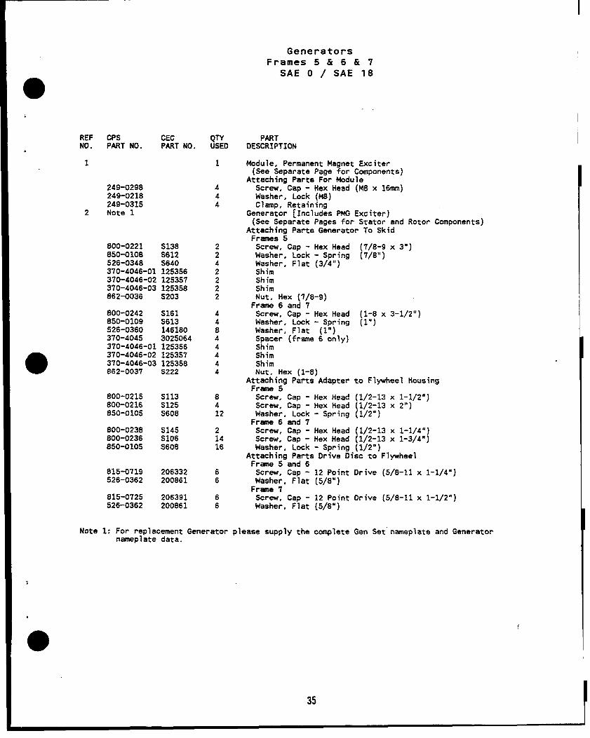
GeneratorsFrames 5 & 6 & 7
SAE
—.
0 / SAE 18
..
%
.
1
34
REF CPS CECNO. PART NO. PART NO.
1
249-0298249-0218249-0315
2 Note 1
800-0221 S138850-0108 S612526-0348 S640370-4046-01 125356370-4046-02 1253!57370-4046-03 125358862-0036 S203
800-0242 S161850-0109 S613526-0360 146180370-4045 3025064370-4046-01 125356370-4046-02 125357370-4046-03 125358$62-0037 S222
800-0215 S113800-0216 S125850-0105 S608
800-0238 S145800-0236 S106850-0105 S608
815-0719 206332526-0362 200861
815-0725 206391526-0362 200861
QTYUSED
1
444
2242
;2
44844444
8412
21416
66
66
I
GeneratorsFrames 5 & 6 & 7
SAE O / SAE 18
PARTDESCRIPTION
Module, Permanent Magnet Exciter(See Separate Page for Components)
Attaching Parts For ModuleScrew, Cap - Hex Head (M8 x 16mm)Washer, Lock (M8)Clamp, Retaining
Generator [Includes PMG Exciter)(See Separate Pages for Stator and Rotor Components)
Attaching Parts Generator To SkidFrames 5
Screw, Cap - Hex Head (7/8-9 x 3“)Washer, Lock - Spring (7/8”)~w, Flat (3/4”)
ShimShimNut, Hex (7/8-9)
Frame 6 and 7Screw, Cap - Hex Head (l-8 x 3-1/2”)Washer, Lock - Spring (l”)Washer, Flat (l”)~mer (frame 6 only)
ShimShimNut, Hex (l-8)
Attaching Parts Adapter to Flywheel HousingFrame 5
Screw, Cap - Hex Head (1/2-13 x 1-1/2”)Screw, Cap - Hex Head (1/2-13 x 2“)Washer. Lock - Spring (1/2”)
Frame 6 and 7Screw, Cap - Hex Head (1/2-13 x 1-1/4”)Screw, Cap - Hex Head (1/2-13 x 1-3/4”)Washer, Lock - Spring (1/2”)
Attaching Parts Drive Disc to FlywheelFrame 5“and 6
Screw, Cap - 12 PointWasher, Flat (5/8”)
Frame 7Screw, Cap - 12 PointWasher, Flat (5/8”)
Note 1: For replacement Generator please supply the completenameplate data.
Drive (5/8-11 x 1-1/4”)
Drive (5/8-11 x 1-1/2”)
Gen Set” nameplate and Generator
35

GeneratorStator Section
Frame 52\
\m
\19
.
36

GeneratorStator Section
Frame 5
;
REFNO.
,
3456
7
8
1516171819202122
;:25262728
31323334
35z
CPSPART NO.
NFSNFSNFSNFSNFS249-0631
249-0304
305-0770305-0778305-0803
249-0398300-3278
249-0398249-0395249-0486
249-0295249-0208249-0287249-0449249-0569302-1851354-0031249-0504249-0289249-0424
CEC QNPART NO. USED
12
;22
8
:1
41
4
:
444
:11331
302-1852-02 3249-0408 2249-0243249-0202249-0242249-0232249-0201249-0202249-0241249-0245249-0202249-02~~249-0256249-0212249-0255249-0272NFS
249-0204249-0205
249-0621249-0622
441188144
611
PARTDESCRIPTION
LidPanel, SidePanel, FrontPanel, RearBracket, AngleLid, Electrical Box - Plain
Attaching PartsScrew, CaptiveRegulator, Voltage
Standard 1 Phase3 Phase (Used with 3 Phase Sensing Module)Manual
Attaching PartsPillar, Threaded
Module, 3 Phase SensingAttaching Parts
Pillar, ThreadedBox. ElectricalModule. Overvoltage
Attaching PartsScrew, Cap - Hex Haad (M5 x 35mm)Washer, Plastic (M5)Nut, Hex - Nylon (M5)
SwitchRFI Suppressor AssyChokeResistor, AdjustableTransformer, Voltage SensingBlock, TerminalPanel, Terminal Block MountingTransformer, CurrentGrille, Inlet - AirScrew, Cap - Hex Head (M1O x 30mm)Washer, Lock - Spring (M1O)Cap. Bearing - OuterCirclipScrew, Cap - Hex Head (M1O x 35mm)Washer, Lock - Spring (M1O)Bearing, BallScrew, Cap - Hex Head (M1O x 50mm)Washer, Lock - Spring (M1O)Cap, Bearing - InnerScrew, Cap - Hex Head (M6 x 65mm)Washer, Lock - Spring (M6)Stator, ExciterBracket, EndStator, Generator (Includes Terminal Studs and Links)
Attaching Parts Stator to AdapterScrew, Cap - Hex Head (M12 x 40m)Washer, Lock - Spring (M12)
Heater. Electrical - Replacement70 Watt, 120 VAC70 Watt, 240 VAC
NFS - Not For Sale
37

GeneratorStator Section
Frame 6
2
1)\
II
\kit$i20
\\
21
23 22
w38
\19
1
+.
●

REFNo.
123456
7
8
1:
111213141516
;:192021222324,25262728293031323334
35
CPSPART NO.
NFSNFSNFSNFSNFS249-042S
249-0304
305-0770305-0778305-0803
249-0398302-3278
249-0398249-0395249-0486
249-0295249-0288249-0287249-0449249-0569302-1851354-0031249-0504249-0289249-0424
CEC C&PART NO.
8
41
421
4441111331
302-1852-02 3249-0513249-0243249-0202249-0510249-0447249-0204249-0205249-0448249-0245249-0202249-0509249-0445249-0212249-0470249-0527NFS
249-0204249-0205
2441188144166“111
88
249-0621 1249-0622 1
NFS - Not For Sale
Generator
Stator SectionFrame 6
PARTDESCRIPTION
LidPanel, SidePanel, FrontPanel, RearBracket, AngleLidAttaching Parts
Screw. CaptiveRegulator, Voltage
Standard3 Phase (Used with 3 Phase Sensing Module)Manual
Attaching PartsPillar, Threaded
Module, 3 Phase SensingAttaching Parts
Pillar, ThreadedBoxModule, Overvoltage
Attaching PartsScrew, Gap - Hex Head (M5 x 35mm)Washer. Plastic (M5)Nut, tiex - Nylon’
SwitchRFI Suppressor AssyChokeResistor, AdjustableTransformer, Voltage SensingBlock, TerminalPanel, Terminal Block MountingTransformer, CurrentGrille, Inlet - AirScrew, Cap - Hex Head (M1O x 301NII,
Washer, Lock - Spring (M1O)Cap, Bearing - OuterCirclipScrew, Cap - Hex Head (M12 x 40mmWasher. Lock - Spring (M12)Bearing, BallScrew. Cap - Hex Head (M1O x 50fMIWasher, Lock - Spring (M1O)Cap, 8earing - InnerScrew, Cap - Hex Head (M6 x 85mm)Washer, Lock - Spring (M6)Stator, ExciterBracket. EndStatorj”Generator (Includes Terminal Studs and Links)
Attaching Parts Stator to AdapterScrew, Cap - Hex Head (M12 x 40mm)Waaher, Lock - Spring (M12)
Heater, Electrical - Replacement70 Watt, 120 VAC70 Watt, 240 VAC
39

/-
‘2
GeneratorStator Section
Frame 7
//
4-
/
.
40

GeneratorStator Section
Frame 7
REFNO.
1
.:456
7
8
161718
19202122232425262728293031323334
35
CPSPART NO.
NFSNFSNFSNFSNFS249-0425
249-0304
305-0770305-0778305-0803
249-0398302-3278
249-0398249-0395249-0486
248-0295249-0288249-0287249-0449249-0569302-1851354-0031
249-0504302-1876249-0289249-0424
302-1852-01302-1852-03249-0583249-0243249-0202249-0510249-0447249-0204249-0205249-0448249-0245248-0202249-0509249-0438249-0218249-0470249-0471NFS
249-0204249-0205
249-0621249-0622
cmPART NO.
QTYUSED
;
:22
8
:1
41
421
44411
;
3331
332441188144166111
88
“11
PARTDESCRIPTION
LidPanel, SidePanel, FrontPanel, RearBracket, AngleLid
Attaching PartaScrew. CaptiveRegulator, Voltage
~tandard “3 Phase (Used with 3 Phase Sensing Module)Manua 1
Attaching PartsPillar, Threaded
Module, 3 Phase Sensing “Attaching Parts
Pillar, ThreadedBoxModule, Overvoltage
Attaching PartsScrew, Cap - Hex Head (M5 x 35nun)Washar, Plastic (MS)Nut, Hex - Nylon (M5)
SwitchRFI Suppressor AssyChokeResistor, AdjustableTransformer
Voltage Sensing (Used on Standard Voltage Generators)Isolation (Used on Medium Voltage Generators)
Block, TerminalPanel, Terminal 810ck MountingTransformer, Current
Used on Standard Voltage GeneratorsUsed on medium Voltage Generators
Grille, Inlet - AirScrew, Cap - Hex Head (M1O x 301mn)Washer. Lock - Spring (M1O)Cap, Bearing - OuterCirclipScrew, Cap - Hex Head (M12 x 40mn)Washer, Lock - Spring (M12)Bearing, BallScrew. Cap - Hex Head (M1O x 50mm)Washer, Lock - Spring (M1O)Cap, Bearing - InnerScrew, Cap - Hex Head (M6 x 85qm)Washer, Lock - Spring (M6)Stator, ExciterBracket, EndStator, Generator (Includes Terminal Studs and Links)
Attaching Parts Stator to AdapterScrew, Cap - Hex Head (M12 x 40mm)Washer. Lock - Spring (M12)
Heater, Electrical - Replacement70 Watt, 120 VAC70 Watt, 240 VAC
● NFS - Not For Sale
41

GeneratorRotor Section
I2
1 ●
42

REFNO..
1
23456789
10111213
CPSPART NO.
249-0408
249-0294249-0307249-0365249-0322249-0437249-0230249-0276249-0277NFS249-0522249-0271249-0237249-0239249-0238249-0240
CEC QTYPART NO. USEO
2
::12
1
GeneratorRotor SectionSAE 0/ SAE 18
Frame 5
PARTDESCRIPTION
Screen, Air - AdapterAttaching Parts
Screw, Cap - Hex Head (M5 x 121run)Washer, Lock - Spring (M5)Washer, Flat (MS)
Adapter, Generator SAE OScrew, Cap - Hex Head (M20 x 75mIn)Plate, PressureDisc. Orive SAE 18SpacerRotor, Generator (Includes Exciter, Key, and Rectifier Assy)Rotor, Exciter (Ooes Not Include Rectifier Assy)KeyRectifier Assy (Includes Diodes)Diode, Forward PolarityDiode, Reverse PolarityVarister
.
NFS - Not For Sale
43

Generator-Rotor SectionSAE 0/ SAE 18
Frame 6
8/1 l’o
44.
.
.
1

I
REFNO.
i
1
23456
:
111213
CPSPART NO.
249-0534
249-0294249-0307249-0365249-0533249-043’7249-0230249-0276249-0277NFS249-0512
249-0237249-0239249-0238249-0240
NFS - Not For Sale
UCPART NO.
QTYUSED
2
::12
1816111
GeneratorRotor SectionSAE 0/ SAE 18
Frame 6
PARTDESCRIPTION
Screen, Air - AdapterAttaching Parts
Screw, Cap - Hex Head (M5 x 1211un)Washer, Lock - Spring (MS)Washer, Flat (MS)
Adapter, Generator SAE OScrew, Cap - Hex Head (M20 x 75mm)Plate, PressureDisc, Drive SAE 18SpacerRotor, Generator (Includes Exciter, Key, and Rectifier Assy)Rotor, Exciter (Does Not Include Rectifier Assy)KeyRectifier Assy (Includes .Diodes)Diode, Forward PolarityDiode, Reverse PolarityVarister
45

GeneratorRotor SectionSAE 0/ SAE 18
Frame 7
.
46
,

;
GeneratorRotor SectionSAE 0/ SAE 18
Frame 7
REF CPS CECNO.
QTYPART NO. PART NO. USED
1
23456789
13
249-0482
249-0294249-0307249-0365249-0481249-0444249-0467249-0469249-0468NFS249-0503249-xxxi249-0237249-0239249-0238249-0566
2
121212
1816“111
31
PARTDESCRIPTION
Screen, Air - AdapterAttaching Parta
Screw, Cap - Hex Head (M5 x 12mm)Washer, Lock - Spring (MS)Washer, Flat (MS)
Adapter, Generator SAE OScrew, Cap - Hex Head (M24 x 7511wII)Plate, PressureDisc, Drive SAE 18SpacerRotor, Generator (Includes Exciter, Key, and Rectifier Assy)
Rotor, Exciter (Doss Not Include Rectifier Assy)KeyRectifier Assy (Includes Oiodes)Diode. Forward PolaritvDiode; Reverse Polarii~Varister
47
NFS - Not For Sale
,.

REFNO.
1
234
5
CD
/
5
CPSPART NO.
249-0497
249-0294249-0307249-0496249-0426
249-0427249-0644
249-0399249-0202249-0313
I4
CEC QTYPART NO. USEO
1
GeneratorPermanent Magnet Exciter
●.
/3
PARTDESCRIPTION
2
Cover. Permament MagnetAttaching Parts For Cover
Screw, Cap - Hex Head (M5 x 12mm)Washer, Lock (M5)
Pillar, ThreadedStator Assembly with FrameRotor Assembly
Frsme 2. 3, 4 GeneratorsFrame 5, 6, 7 Generators
At~;ing Parts For Rotor
Washer, Lock (M1O)Pin, Dowel
w
48
ICOUTROL SECTION
TABLE OF CONTENTS
.
Control, Generator Set . . . . . . . . . . . . . . . . . . . . . . . . . . . . . . . ..*... . . . . 53
Control Panel, Generator (Sets with LEO Indicator Lights) . . . . . . 55
Control Panel, Generator (Sets with Bulb Indicator Lights) . . . . . 5?
Control Panel, Engine (Sets with LED Indicator Lights) . . . . . . . . . 5g
Control Panel, Engine (Sets with Bulb Indicator Lights) . . . . . . . . 61
Control Miring Harnesses (Sets with LED Indicator Lights) . . . . . . 63
Control Wiring Harnesses (Sets with Bulb Indicator Lights) . . . . . 65
Control Internal Components (Sets with LED Ind Lights) . . . . . . . . . 66 -
Control Internal Components (Sets with Bulb Ind Lights) . . . . . . . . 67
● Control Alarm Flodule . . . . . . . . . . . . . . . . . . . . . . . . . . . . . . . . . . . . . . . . . . 68
51

Generator Set Control
“
52

Generator Set Control
REFNO.
1
2
345
678
CPSPART NO.
NFS
862-1001850-1040NFS
815-0701NFSNFSNFS
337-2402402-0610
CECPART NO.
NFS
7029970189NFS
3016086NFSNFSNFS
3016849204493
302-1866-05 3011674302-1866-09 3011678302-1866-13 3011682302-1866-15 3011684302-1866-17 3011686
302-1866-21 3011690302-1866-24 3014135302-1866-27 3051479302-1866-28 3051480
QTYUSED
1
861
6111
14
33333
3333
PARTDESCRIPTION
Control, Generator Set (See Items 3 Thru 5 for Components)Attaching Parts for ControlNut, Hex (1/4-20)Washer, Lock - Spring (1/4”)Cover, ControlAttaching Part for CoverScrew, Machine - Round Head (1/4-20 x 1/2”)Control Panel, Generator (See Separate Pages for Components)Control Panel, Engine (See Separate Pages for Components)Internal Components and Wiring Harnesses (See Separate Pages
Selection)Lead, Electrical - GroundMount, VibrationTransformer, Current (Select as Required)
400:5 Ratio (Used with 200/400 AMP Ammeter)600:5 Ratio (Used with 300/600 AMP Armneter)800:5 Ratio (Used with 400/800 AMP Ammeter)1000:5 Ratio-(Used with1200:5 Ratio (Used with
Single Scale Ammeter)1600:5 Ratio (Used with2000:5 Ratio (Used with2500:5 Ratio (Used with3000:5 Ratio (Used with
Scale Ammeters)
500/1000 AMP Geter)600/1200 AMP Ammeter and 1200 AMP
800/1600 AMP Ammeter)1000/2000 AMP Ammeter)2500 AMP Single Scale Ammeter)1500/3000 AMP & 3000 AMP Single
53

Generator Control Panel
With E D Indicator Lights
10
\@
@ 9
Q
~
@/
@Q@
‘@Q‘8
I
EmE!a
--7- ● .+
.“—. . .
.IW.UU.I 8-S*—. w-—
/20
7
\
@k
.
14
●
54

Generator Control PanelWith L E D Indicator Lights
a
REFNO.
●
1
23456789
:;
121314151617191920
CPS CECPART NO. PART NO.
812-0075306-352398-5387870-0437306-3522870-0451 70646300-3283 3053064300-3282 3053063300-3281 3053062
308-0885-05 3015057308-0885-06 30150S8308-0885-11 3055738308-0885-08 3035149322-0398 3035016322-0397-01 3035018322-0406 3056064322-0404-01 3056065322-0405 3056063308-0884 3015860303-0288 3058451302-1860 3056071
302-1856 3015043302-1858 3015044
302-1871-05 3039530302-1862 3015035302-1863 3015036302-1871-06 3051478302-1864 3015037302-1865 3015038302-1871-01 3015039302-1871-09 3059965302-1871-10 3059966
302-1871-02 3015040302-1871-03 3015041302-1871-04 3015042302-1871-07 3051479302-1871-08 3051480
QTYUSED
REF
211714
;1
1111222221
;
11
i111
:11
11111
PARTDESCRIPTION
Harness, Wiring (See Separate Pages for Selectionand Applications)
Screw, Machine - Round Head (#8-32 x 1/4”)Shield, SwitchDecal (Warning)Nut, Acorn - PlasticShield, MetersNut, Self-1ocking - Hex (#8-32 )Printed Circuit Board - 10 LED LightsPrinted Circuit Board - 4 LED LightsPrinted Circuit Board - 2 LED LightsSwitch, Toggle
(AUTOSTART oN/oFF/sTANo8Y)(SyNt2HR0N121NG)
Switch, Toggle (ALARM SILENCE)Switch, Toggle (PANEL LIGHTS)Light.” Panel (Less Bulb)8ulb, IncandescentLens, Clear (SYNCHRONIZING)Bulb, IncandescentSocket, LightSwitch, Selector(Includes Knob)RheostatWattmeterMeter (TYPICAL)
VoltmeterFrequency/RPMAmmeter (Select as Required)
DUALSCALE200/400 AMP300/600 AMP400/800 AMP500/1000 AMP600/1200 AMP800/1600 AMP1000/2000 AMP1500/3000 AMP2000/4000 AMP
SINGLE SCALE1200 AMP1600 AMP2000 AMP2500 AMP3000 AMP
55

Generator Control PanelWith Bulb Indicator Lights
-’%4
“.-. .uJW
. . . . . . . .
k-a **.U... .-.w.f
-..9---
4
19
9
-\
/
a/ QwO.
5
/
,/00“,/0
14
15h
‘\
% “%
/
,.
w
56
.

Generator Control PanelWith Bulb Indicator Ljghts
>
REFNO.
.
1
89
1011
121314
●151617
1819
CPS CECPART NO. PART NO.
812-0075306-352398-5387870-0437306-3522
30187953018796301879730187983018799
301880030146673015133
308-0885-05 3015057308-0885-06 3015058308-0885-11 3055738308-0885-08 3035149322-0398 3035016322-0397-01 3035018
3015018
302-1856 3015043302-1858 3015044
302-1871-05 3039530302-1862 3015035302-1863 3015036302-1871-06 3051478302-1864 3015037302-1865 3015038302-1871-01 3015039302-1871-09 3059965302-1871-10 3059966
302-1871-02 3015040302-1871-03 3015041302-1871-04 3015042302-1871-07 3051479302-1871-08 3051480308-0884 3015860303-0288 3058451
QTYUSED
REF
2
:71
41~
28
712
11
;221
11
111
i1111
11
:111
PARTDESCRIPTION
Harness, Wiring (See Separate Pages for Selectionand Applications)
Screw, Machine - Round Head (#8-32 x 1/4”)Shield, SwitchDecal (Warning)Nut, Acorn - PlasticShield, MetersLens, Indicator Light
OrangeRedGreenWhite (SYNCHRONIZING)
8ulb, IncandescentSocket & Socket with Switch
Socket, LightSocket, Light with Push Switch
Light, Indicator - Red Lens (UPPER/LOWER SCALE INDICATING)Switch, Toggle
(AuTOSTART-ON/OFF/STAN08Y )(SYNCHR0N121NG)
Switch, Toggle (ALARM SILENCE)Switch, Toggle (PANEL LIGHTS)Light, Panel (Less 8ulb)8ulb, IncandescentWattmeterMeter
VoltmeterFrequency/RPMAmmeter (Select as Required)
DUAL SCALE200/400 AMP300/600 AMP400/800 AMP500/1000 AMP600/1200 AMP800/1600 AMP1000/2000 AMP1500/3000 AMP2000/4000 AMP
SINGLE SCALE1200 AMP1600 AMP2000 AMP2s00 AMP3000 AMP
Switch, Selector(Includes Knob)Rheostat
57

Engine Control PanelWith Lights
10’
il
.
\
58
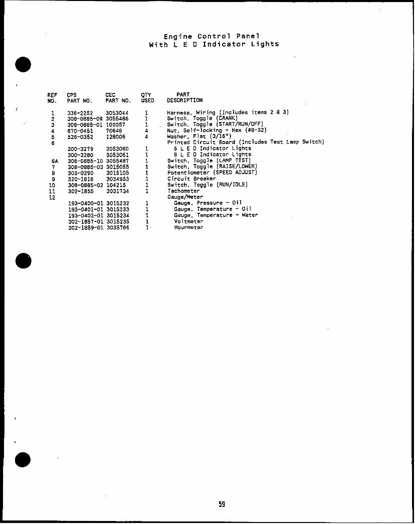
Engine Control PanelWith L E D Indicator Lights
,
REFNO.
3456
6A78
1:1112
CPS CECPART NO. PART NO.
338-2252 3053044308-0885-09 3055486308-0885-01 102057870-0451 70646526-0352 128006
300-3279 3053060300-3280 3053061308-0885-10 3055487308-0885-03 3015055303-0290 3015105320-1616 3034953308-0885-02 104215302-1855 3031734
193-0400-01 3015232193-0401-01 3015233193-0402-01 3015234302-1857-01 3015235302-1859-01 3035766
QTYUSEO
11144
11111111
11111
PARTDESCRIPTION
Harness, Wiring (Includes itemsSwitch, Toggle (CRANK)Switch, Toggle (START/RUN/OFF)Nut, Self-1ocking - Hex (#8-32)Washer, Flat (3/16”)Printed Circuit Board (Includes
5 L E D Indicator Lights8 L E D Indicator Lights
Switch, Toggle (LAMP TEST)Switch, Toggle (RAISE/LOWER)Potentiometer (SPEEO ADJUST)Circuit BreakerSwitch, Toggle (RUN/IDLE)TachometerGauge/Meter
Gauge, Pressure - OilGauge, Temperature - OilGauge, Temperature - WaterVoltmeterHourmeter
2&3)
Test Lamp Switch)
59

Engine Control PanelWith Bulb Indicator Lights
6
I 5
3-.
89
b\ &/ . ..
//b
<% .V. ~,
/‘“\
12
7
10’
F
,
●
60

.
REFNO.
123456789
101112
CPS CECPART NO. PART NO.
3035126308-0885-09 3055486308-0885-01 102057
301879530187993018800
308-0885-03 3015055303-0290 301s105320-1616 3034953308-0885-02 104215302-1855 3031734
193-0400-01 3015232193-0401-01 3015233193-0402-01 3015234302-1857-01 3015235302-1859-01 3035766
QTYUSED
;13
:11111
11111
Engine Control PanelWith Bulb Indicator Lights
PARTDESCRIP
HarnessSwitch,Switch.
ION
Wiring (Includes items 2 & 3)Toggle (CRANK)Tomle (sTART/RuN/OFF)
Lens, Ligh;-(ORANGE) -8ulb, LightSocket, LightSwitch, Toggle (RAISE/LOWER)Potentiometer (SPEED ADJUST)Circuit BreakerSwitch. Toggle (t3JN/IOLE)TachometerGauge or Meter
Gauge, Pressure - OilGauge, Temperature - OilGauge, Temperature - WaterVoltmeterHourmeter
●
61

.,
Set Control - Wiring Harnesses(Sets With LED Indicator Lights)
●
I
d
..
.
,
62

REFNO.
345
67
89
1011
CPS CECPART NO. PART NO.
338-2255 3053048338-2258 3056066338-2250 3035147338-2253 3053046338-2383 30.53033
308-0885-06 30150583055739
860-0003 3043636850-0010 3043637338-2312 3056089338-2256 3056061
308-0885-08 3035149338-2248 3035132
12
338-2301-03 3053039338-2301-04 3053040338-2301-05 3053041338-2301-06 3053042338-2301-07 3053043331-0525 204494338-2251 3044442
Set Control - Wiring Harnesses(Sets With LED Indicator Lights)
QTYUSED
1
i11
12
4421
11
1111111
PARTDESCRIPTION
Harness, Wiring (PCB TO LED PCB)Harness, Wiring (PCB TO WATTMETER)Harness. Wiring (PCB TO VOLT/AMP SELECTOR SWITCH)Harness. Wiring (PCB TO AC METER)Harness, Wiring (PCB TO RESISTORS AND SYNCHRONIZING SWITCH;
Includes The Resistors and Switch)Switch, Toggle (SYNCHRONIZING)Resistor, Wirewound with Mounting BracketAttaching Parts for Resistor
Nut, HexWasher, Lock - Spring
Harness, Wiring (HIGH/LOWWYE AOAPTER)Harness, Wiring (PCB TO PANEL LIGHTS AND SWITCH; Includes
The Switch)Switch, Toggle (pANEL LIGHTS)Harness Assembly, Wiring (ENGINE CONTROL PCB TO GENERATOR
CONTROL PCB)Harness Assernoly, Wiring - With Shielded Leads (ENGINE WIRING
HARNESS TO ENGINE CONTROL PCB; Select Length as Applicable)9.3 Feet11.3 Feet15.3 Feet25.3 Feet50.0 Feet
Gasket, ConduitHarness, Wiring {PCB TOGEN TERMINAL BLOCK)
63

Set Control - Wiring Harnesses(Sets With Bulb Indicator Lights)
4
J II
64

REFNO.
1
23456
7
89
;?
1213
14
13
CPS CECPART NO. PART NO.
3035145
3015118308-0885-04 3015056
3035142338-2250 3035147
3035144
3035147
308-0885-06 30150583015109
860-0003 3043636850-0010 3043637338-2249 3035140338-2256 3056061
308-0885-08 3035149338-2248 3035132
338-2276-01 3035127338-2276-02 3035128338-2276-03 3035129338-2276-04 3035130338-2276-05 303.5131331-0525 204494
Set Control - Wiring Harnesses(Sets With Bulb Indicator Lights)
QTYUSED
1
:
:1
1
12
4421
11
111111
PARTDESCRIPTION
Harness, Wiring (PC8 TO HORN, SWITCH AND INDICATOR LIGHTS;Includes The Horn and Switch)
HornSwitch, Toggle (ALARM SILENCE)Harness, Wiring (PCB TO WATT TRANSDUCER)Harness, Wiring (PCB TO VOLT/AMP SELECTOR SWITCH)Harness. Wiring (PCB TO AC METER AND RED INOICATOR LIGHTS:
Includes Red Indicator Lights)Harness, Wiring (PCB TO RESISTORS, SYNCHRONIZING LIGHTS ANO
SWITCH; Includes The Resistors and Switch)Switch, Toggle (SyNCHR0N121NG)Resistor, Wirewound with Mounting BracketAttaching Parts for Resistor
Nut, HexWasher, Lock - Spring
Harness, Wiring (HIGH/LOWWYE AOAPTER)Harness, Wiring (PCB TO PANEL LIGHTS AND SWITCH; Includes
The Switch)Switch, Toggle (pANEL LIGHTS)Harness Assembly, Wiring (ENGINE CONTROL PC8 TO GENERATOR
CONTROL PCB)Harness Assembly, Wiring (ENGINE WIRING HARNESS TO ENGINE
CONTROL PCB; Select Length as Applicable)5.3 Feet7.3 Feet9.3 Feet11.3 Feet15.3 Feet
Gasket, Conduit
65

Set Control - Internal Components(Sets With LED Indicator L_ights)
m
.L
.
REF CPS CEC QTYNO. PART NO. PART NO. USED
307-2623 3034957i 307-2622 3034958 :3 338-2254 30530474 308-0885-05 301.5057 ;5 300-327’7 3054341 1
815-0702 70310 4850-1020 70262 4
6 151-0634 3044195 1
815-0702 70310 4850-1020 70262 4
7309-0574 3036453 1300-3591 3035015 1
815-0702 70310 4850-1020 70262 4
8 307-2623 3034957 19 307-2684 3034962 1
PARTDESCRIPTION
Retainer, RelavReiay “Harness, Wiring - AutoStart to LEDs (Includes Switch)Switch, Toaale (AutoStart)Board, Pri;~ed Circuit - AutoStartAttaching Parts for 8oard
Screw, Machine - Pan Head (#6-32 x 3/8”)Washer, Lock - Spring (#6)
Cantrol, GovernorAttaching Parts for Board
Screw. Machine - Pan Head (#6-32 x 3/8”)Washer, Lock - Spring (#6)
Control or Circuit Board (Select as Applicable)Control, OverspeedBoard, Adapter - Hydraulic Governor
Attaching Parts for 8oardScrew, Machine - Pan Head (#6-32 x 3/8”)Washer, Lock - Spring (#6)
Retainer, RelayRelay
66

9.b
●
.
,
●
Set Control - Internal Components(Sets With Bulb Indicator Lights)
~
REFNO.
12345
6
7
8
1:
11
CPS CECPART NO. PART NO.307-2623 30349s7307-2622 3034958
3035143308-0885-05 3015057300-3277 3054341
815-0702 70310850-1020 70262151-0634 3044195
815-0702 70310850-1020 70262
309-0574 3036453300-3591 3035015
815-0702 70310850-1020 70262307-2623 3034957307-2684 3034962
3015019
30187923015017
867-0028 70273850-1030 70621
1 Switch, Toggle-(AutoStart)1 Board, Printed Circuit - AutoStart
Attaching Parts for Board4 Screw, Machine - Pan Head (#6-32 x 3/8”)4 Washer, Lock - Spring (#6)”1 Control, Governor
Attaching Parts for Board4 Screw, Machine - Pan Head4 Washer, Lock - Spring (#6)
Control or Circuit Board (Se1 Control, Overspeed1 8oard, Adapter - Hydraulic
Attaching Parts for Board
#6-32 X 3/8”)
ect as Applicable)
Governor
Screw,-Machine - Pan Head (#6-32 x 3/8”Washer, Lock - Spring (#6)
Retainer, RelayRelayHarness, Wiring - Transducer to WattmeterAttaching Parts for Harness
21
44
Screw,-Self-Tapping - Round HeadTransducer, WattAttaching Parts for Transducer
Nut. Hex (#10-32)Washer, Lock - Spring (#10)
67
6

Set Control - Alarm Module
6
REF CPS CECNO. PART NO. PART NO.
1 338-2257 30.560622
300-3286 3054296300-3287 305L1297
3Note 1 Note 2Note 1 Note 2
870-0451 70646526-0352 128006
4 Note 3 30626915 333-01336 308-0885-11 30557387 333-0405-02 149806
QTYUSED
1
11
11
44
;
:
PARTDESCRIPTION
Harness, Wiring - Alarm 8oard to Gen Control BoardModule, Alarm (Includes PC Board, Horn, Switch and Electrical
iescs to Horn. Switch and Generator Terminal Board)Sets with Four Fault IndicatorsSets with Six Fault Indicators
Board, Printed Circuit - Alarm Module (Includes Fuse)Sets with Four Fault IndicatorsSets with Six Fault Indicators ~
Attaching Parts for BoardNut, Self-locking - Hex (#8-32)Washer, Flat (#/16”)
FuseHorn, Electrical - 24VDCSwitch, ToggleHorn, Electrical with PC 8oard and Weathertight Box
for Outdoor Applications. NOT PART OF SET ALARM MOOULE!
NOTES: 1. Not stocked as replacement item. order applicable Item 2 for replacement.2. Not Stocked as replacement item, order applicable Item 2 for replacement3. Not stocked as replacement item.
68