The following catalog has gaps in its page numbers, or doesn’t …n0nas/manuals/onan/948-0305...
22
The following catalog has gaps in its page numbers, or doesn’t have any numbers. We have chosen to leave the page numbering in the order that Acrobat assigns it.
-
Upload
vuongtuong -
Category
Documents
-
view
223 -
download
5
Transcript of The following catalog has gaps in its page numbers, or doesn’t …n0nas/manuals/onan/948-0305...

The following cataloghas gaps in its pagenumbers, or doesn’thave any numbers.We have chosen to
leave the pagenumbering in theorder that Acrobat
assigns it.

PARTS CATALOG
FOR
WB
ELECTRICGENERATING SETS
948-030 !j5 AlQHL74
(Replaces 6H71)pmld M U.S.A,
PARTS CATALOG
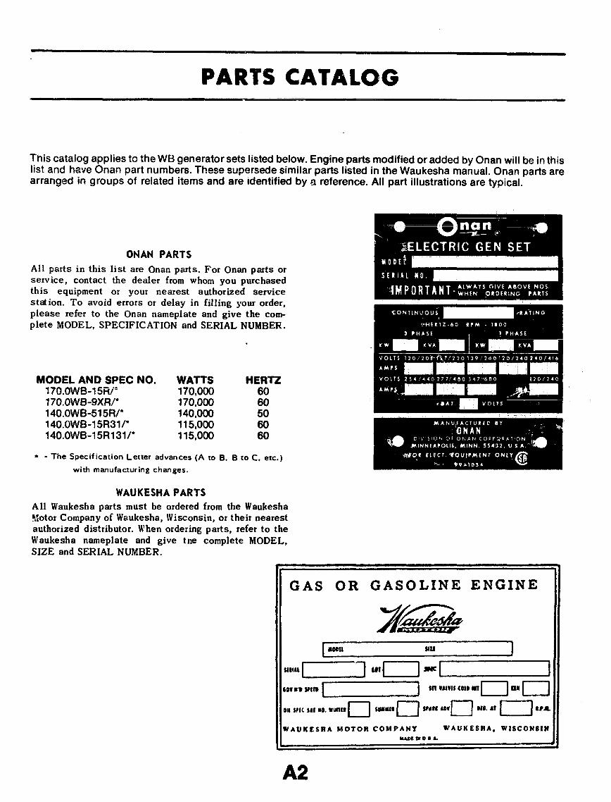
This catalog applies to the WE?generator sets listed below. Engine parts modified or added by Onan will be in thislist and have Onan part numbers. These supersede similar parts listed in the Waukesha manual. Onan parts arearranged in groups of related items and are Identified by a reference. All part illustrations are typical.
ONAN PARTS
All parts in this list are Onan parts. For Onan parts OKservice, contact the dealer from whom you purchasedthis equipment or your nearest authorized servicestation. To avoid errors or delay in filling your order,please refer to the Onan nameplate and give the com-plete MODEL, SPECIFICATION and SERIAL NUMBER.
.
MODEL AND SPECIumv$mi ml’170.OWB-!?XFV140.owB-515Rr140.owB-15R31r
NO. WATTS HERTZ170,000 60170,000 60140,000 50115.000 60
140.owB-15R131/* 115;000 60
* - The Specification Letter advances (A to B, B to C, etc. )
with manufacturing changes.
WAUKESHA PARTS
All Waukesha parts must be ordered from the WaukeshaMotor Company of Waukesha, Wisconsin, or their nearestauthorized distributor. When ordering parts, refer to theWaukesha nameplate and give tne complete MODEL,SIZE and SERIAL NUMBER.
v 1
GAS OR GASOLINE ENGINE
~fii+
.,l.[+=+ “,/—] :[~1
c“w’”t”~ “’’”’’’’O1’”O”’OWt,’,,,”mt.n SU+-J VW*VH 016.,?I—-*,A
WA UK ESHA MOTOR COMPANY WA UUESRA, WISCONS1tlwEuo#&
b ●Ak
A2

/ /L. —--- --
II&[11Y10
36
I
b
....,...:.
9 ‘“
hu’i2
25
da‘e)
&“3
-ua-
FL37
n
A3

REF. p~~~ Q~yc PARTNO. NO. USED DESCRIPTION
REF. PART WV. PARTNO. NO. USED DESCRIPTION
~ 148= T Vent, Gas - Carburetor - Gas-Gasoilne and LPG -Gasoline Sets
27 152-0120 1 Control, Vernier Throttle -
193G 1 Sender, Oil Pressure Gauge193-0109 1 Sender, Water Temperature
12
Gauge309-0178 1 Switch, High Water Temp.309-0169 1 Switch, Lnw Oi! Pressure505-0117 1 Bushing, Reducer (1/2 x
3/8” )505-0098 1 Nipple, Oil Sender and Switch505-0059 1 Tee, Oil Sender and
Switch (1/8’)505-0498 Bushing, Reducer - Oil DrainCABLE, BATTER;416-0444 1 Positive416-0445 NegativeCABLE, BATTER; JUMPER416-0473 1 Begin Spec L416-0446 1 Used on Spec l-f and J133-0160 1 Baffle, Heat - Temperature
Cut-Off Switch312-0058 Condenser, Ignition Coil314-0156 : Suppressor, Spark Plug314-0006 1 Suppressor, Coil155-1166 1 Shield, Heat (Housed Sets)505-0100 1 Nipple, Oil Drain (1/2 x
4-1/2”)505-0059 1 Elbow, Street (112 X ~“ }140-1131 “1 Cleaner, Air (Includes Element)140-1156 1 Element, Air Cleaner140-1130 1 Clamp, Air Cleaner Mounting140-1132 1 Cap, Air Cleaner140-1125 1 Bracket, Air Cleaner Mtg.140-1126 1 Bracket, Air Cleaner Mtg. -
(Used with Water CooledManifold) Optional
.-. a... n3U.5-UOLL 2 Clamp, Air Cleaner Hose309-0269 1 Switch, Low Engine
Temperature - Optional
345 28
29
151-0230 1Optional
Bracket, Vernier ThrottleControl - Optional
67
REGULATOR, GAS149-0596 174&Ot335 1505-0042 1
Natural Gas SetsLPG Fuel SetsElbow (1-1/4” X 90°) -
Gas Fuel Sets OnlyNipple (1-1/4 x 3“) - Gas
Fuel Sets OnlyElbow (1-1/4 x 45°) - Gas
Fuel Sets OnlyNippie, Close - Gas Fuel
Sets OnlyBracket, Heat Exchanger Mtg.Nipple, Exhaust (4 x Close) -
Water Cooled Manifold UnitsElbow, Exhaust (4”) - Water
Cooled Manifold UnitsStrainer, Fuel - Gas -Line, Fuel - GasValve, Solenoid - GasValve, Drain - OilNipple, Half - Oil DrainClamp, Hose - Oil Dre!nHose - Oil DrainHose, Air Cleaner (Order 43”
89
30
31 505-0258 1
10 32 505-0046 1
33 505-0177 111
3435
130-0851 1505-0164 112
13141516
36 505-0171 1
3738394041424344
149-0751 1503-0273 1307-0641 1504-0011 1505-0185 1503-0197 1503-0316 1
As Req.
45 146-072146 503-0621 ;47 503-0659 148 148-0724 1
49 504-0078 2
of Bulk Hose #503-0620)Carburetor, Gas - Begin Spec JClamp, Hose - Begin Spec JHose, Adapter - Begin Spat JAdapter, Carburetor - Begin
Spec JValve, Shutoff (Water Filter
2425
Lines) - Optional
RESERVOIR TANK GROUP
PARTOESCRIPTION
PARTNo.
OTY.WED
REF.No.
1
Tank, ReservoirBracket, Tank MountingBand, TankValve, Tank Shut-OffElbow, Compression Male -
BrassPlug, Pipe - Square Head
(1/8)Line, Fuel - Flexible - (1) Pump
to Reservoir Tank, (1)Reservoir Tank to Carburetor
Bushing, Reducer - RestrictedScrew, Cap (1/4-20 x 3/4]
- Tank MountingNut, Hex (1/4) - Tank Mtg.Washer, Lock - Tank MountingWasher, Flat - Bracket MountingWasher, Lock - Bracket Mtg.Screw, Cap (1/2-13 x l“) -
Bracket Mounting
159-0668159-0986159-0871504-0059502-0183
11111
6 505-0057 2
9159-0705800-0005
89
860-0013850-0040526-0035850-0060800-0090
1011121314
A4

ALTERNATOR AND STARTER”M6TOR GROUP
I REF. PAFtT
I
PARTNO. NO. :ST9 DESCRIPTION
——
if 191-0688 1 tAlternator, Charge - IncludesRegulator and Fan(Motorola #70D44039B04)
2 191-0733 1 Regulator, Alternator3 191-0649 1 Pulley, Alternator4 191-0725 1 Guard, Alternator Belt5 600-0095 1 Screw (1/2-13 x 2-1/4) -
Alternator Mounting6 650-0060 1 Washer, Lock (1/2) -
Alternator Mounting7 662-00?6 1 NW, HQm, , -)AWlli~ . A~temator
:Aa. ,R*;fl-w,””, vu,,~
8 312-0058 1 Condenser. Alternator -0.1 Mfd.
9 511-0056 1 Belt. Alternator Drive10 191-0905 1 Bracket, Alternator Mounting11 191-0869 1 Bracket, Alternator Adjustment12 191-0852 1 ● Motor, Starting (Delco Remy
#1113892)13 600-0133 3 Screw (5/8-1 1 x 2-1/4”) -
Starting Mounting14 850-0070 3 Washer, Lock
“ - For components, contact your nearest Delco RemyDealer or Delco Remy Division of Generator MotorsCorporation, Anderson, Indiana 46011.
~ - For components, contact your nearest Motorola Dealeror Motorola Automotive Products, Inc., 940f W. Grand
14 Ave.. Franklin Park, Illinois 60131.
WATER FILTER GROUP - OPTIONAL
t 1aJ
{~
&iii@
‘–-aREF. PART PARTNO. NO. :SYD DESCRIPTION
eB
7 130-0497 1 Filter, Water - Complete2 ELEMENT REPLACEMENT KIT, WATER FILTER
-. 130-0771 1 Chromate Element (Include$
D
(Parts Marked ‘) - OriginalEquipment
Qa__’” ?30-0772 1 All Purpose, Year Around.b ,, Element (Includes Parts
.1
Marked t)3 ELEMENT, FILTER
- -- 130-0775 1 “Chromate Element
4—--6<LZ=L J
130-0776 1*S ‘tAll Purpose, Year Around
=~=. 4 130-0780 1 ●tPlate, Sacrificial=~ --
@
5 130-0778 1 “tGasket, Cover-%
“ - Included in #130-0771 Element Replacement Kit.---2’-- t - Included in #130-0772 Element Replacement Kit.
P-” ~
@,
o
0
9

1
ANT[-DIE=I lN~ ICONTROL AND CHOKE GROUP —-------GAS-GASOLINE AND LPG-GASOLINE SETS
44 45
I
.,q+
.. . . . .. . . . ... . . . ...’
26279
Q
i.13 ~3f3
- .S’--.4 ,I* ,1
%
● - 0.
. 1
0 I. .I L
42
itEF. PARTNo. NO.——
150-0147; 145-01583 145-04354 526-0201
5 145-02016 145-04377 307-11418 145-03439 153-0317
10 153-005111 153-030412 153-044613 153-030514 153-028715 148-031716 153-028817 153-028218 153-030319 518-004720 153-028321 603-0002
22 508-000723 812-005924 853-00032!3 870-005326 813-0100
QTY.USED
11
;
111111111111111
:
22221
PARTDESCRIPTION
stlJd, AdjustingSpring, ThrottieLink, Throttle SpringWasher, Spacer (7/16” 0.0.
x 17/64” I.D.)Bracket, Solenoid MountingLink, SolenoidSolenoid and Lead AssemblyBracket, Throttle SpringChoke, Auto. (Sisson)Cover Assembly, ChokeArm, Choke LockAdapter, ChokeBracket, Choke MountingShaft, ChokeCounterweight, Choke ShaftPlate, ChokeArm, ChokeRod, ChokeClip, Rod EndArm, Choke Over-RideScrew, Set - (2) Adapter
Mounting (1) CounterweightMounting
Washer, Choke Shaft SealScrew, Choke Plate MountingWasher, Choke Plate Mtg.Nut, Hex (10-32) - Adj. StudScrew (10-32 x 1/2) - Choke
Lock Arm Mounting
REF. PART OTY. PARTNO. NO. USED DESCRIPTION
—— —
27 232-0979 1 Spring, Choke Lock ArmMounting
28 800-0005 1 Screw (1/4 x 3/4), ThrottleSpring Link
29 86ZOOOI 1 Nut, Hex (1/4-20) -Throttle Scwin!aLink
303132
3334
35
363738394041424344454647
860-0008 4 Nut, Hex - Soleioid Mtg.812-0082 4 Screw, Solenoid MountingSCREW, CHOKE PLATE STOP813-0105 1813-0111870-0053 1815-0178 1
861-0008 1
526-0018 1850-0040800-0003 :860-0013 2850-0040 2854-0014812-0082 ;850-0025 2308-0150 1308-0068 1854-0007 4850-0030 3
10-32 X 1“10-32 X 2-1/48’Nut, Hex (10-32)Screw (10-32 x 5/8) - Choke
Arm MountingNut, Hex (10-32) - Choke
Arm MountingWasher, Flat (1/4)Washer, Lock (1/4)Sc::e;hoke Mounting
Washer, Lock [1/4)Washer, ShakeproofScrew, Choke Cover Mtg.Washer, LockPlate, Switch MountingSwitch, ToggleWasher, LockWasher, Lock

28
1“1
A?

ftEF. PART QTY. PARTNO. NO. USED DESCRIPTION——
1 BASE, SKID403-1134 1 Begin Spec L403-0965 1 Spec H through J
2 PANEL, L, ,~E (Housed Sets)405-2165 2 Begin Spec L405-1878 2 Spec H through J
3 405-1856 1 Panel, Lower Rear Housing(Housed Sets)
4 405-1858 2 Panel, Rear Lower (HousedSets)
5 405-1877 4 Panel, Door - Sidz (HousedSets)
6 405-1875 8 Panel, Louver (Housed Sets)7 PANEL, TOP (Housed Sets)
405-1920 1 Begin Spec L405-1886 1 Spec H through J
8 405-1880 1 Panel, Rear Door (HousedSets)
9 406-0157 1 Handle, Door (Housed Sets)10 406-0089 1 Catch, Door (Housed Sets)11 405-1883 1 Panel, Rear (Housed Sets)12 BRACKET, PANEL MOUNTING
405-2016 2 Unhoused Sets - Begin Spec L405-1854 2 Unhoused Sets - Spec H thru J405-2016 6 Housed Sets - Begin Spec L405-1854 6 Housed Sets - Spec H thru J
REF. PART QTY.NO. NO. USED——
13 405-1884 13A m~-nw.- -. 115 301-3154 116 301-3155 117 301-3156 218 301-3156 1
19 405-1873 2
20 337-0090 121 508-0001 1
22 MOUNT, VIBRATION402-0371 2492-0384 2
23 405-1872 1624 818-0150 16
25 405-1888 2
26 403-0968 227 416-0635 2
28 155-1193 129 155-1192 2
,
PARTDESCRIPTION
Panel, FrontSupport, Engine MountSaddle, Control Box HousingHousing, Control BoxPanel, Control Box HousingPanel, Control Box Housing
(Top) Unhoused Sets OnlySupport, Center Housing
(Housed Sets)Strap, GroundGrommet, Rubber - Control Box
Housing
Engine EndGenerator EndClip, Door (Housed Sets)Rivet, Door Clip Mounting
(Housed Sets)Bracket, Radiator and Shroud
SuppotiMount, Front EngineStrap, Battery Hold-down -
Begin Spec LShield, Heat (Housed Sets)Bracket, Heat Shield-
(Housed Sets) Begin Spec L
COOLING SYSTEM GROUP
~iiiiii2_J
II I a
~p ‘.,.\
A .109 130-0843
REF. PARTNO. NO.
T RADIATOR130-0836130-0837
2 130-04493 504-00284 130-08425 130-08486 503-06157 503-03548
II II \
WI
QTY.USED
111112141
211
PARTDESCRIPTION
Drjj Manifo!c! LMtsWater Cooled Manifold UnitsCap, RadiatorValve, Radiator DrainShroud, RadiatorBrace, Radiator SupportHose, Radiator - LowerClamp, HoseHose, Radiator - Upper
(Order 26” of Bulk Hose#503-0623)
Bracket, Radiator SupportShroud, FanGuard, Fan
A8

‘\ \
/’/
GENERATOR GROUP—.—— --- m--- m- mA97
REF. PART PART HEP. rAn I Ucl. ?-inn m
NO. NO. :SYD DESCRIPTION USED DESCRIPTION——
T Rotor Assembly, Wound - i :52-% ~ Washer, Searing Retainer1“
2 205-00953 510-01014*5 515-01456 15&1456
7 BOLT, PLACE805-0033805-0032
8 150-07179 211-0185
10 234-036611 232-220812 201-1739
13 232-203714 234-037015 234-036116 509-0125
11111
8611
:1
;11
. Includes Coliector RingBlowerBearingStator Assembly, WoundKey, E~citer RotorBracket and Cc@act Assy.
f?.~in Spec L
i2rive Disc to HubDrive Disc to EngineSw;::nwembly, Overspeed
Scr&, GeneratorBracket, Generator MountingRotor Assembly, Wound -
Exciter - (See SeparateGroup for Components)
Disc, Generator DriveGrille, Generator Air InletWrapper, Generator End BellSeal, “O” Ring - Bearing
1819
202122
23
242526272829
600-0513220-1528
232-2102520-0735305-0481
305-0491
800-0163850-0079526-0123232-1393515-0211338-0521
11
142
1
222111
Screw, Bearing-RetainerStator Aesembly, Wound -
ExciterSpacer, BearingStud, End BellSpacer, Voltage Regulator
Chassis MountingChassis Assembly, Voltage
Regutator - (See SeparateGroup for Components)Used on Spec H and J
Screw, HHC, 3/4-10x 4Lockwasher, 3/4Washer, Flat -314Hub, DriveKey, WoodruffHarness Assembly, Voltage
Regulator
Refer to factory giving complete Model, SPec and SerialNumber from the Onan nameplate.

EXCITER ROTOR GROUP
_snJ!i
358+016 3 Rectifier, Diode - Positive1 Heat Sink, Rectifier -
Positive”3584X)15 3 Rectifier, Diode -N6gative
1 Heat Sink, Fk@fier-Neg@ive
2 Grommet, Rubber,332-0050 .2 CWynp, Cable508-0124 4 @$hing, Insulating508-0156 4 Washer, In$uiating
.
REF. PAFtT PAFiTW. No. :SYD DESCRIPTION——
,,
VOLTAGE REGULATOR GROUP - SPEC H & J
REF. PARTNO. NO.——
1 30543491
2 305-04823 358-0029
4 364-00145 359-0035
6 363-00537 332-10438 508-00029 332-1266
10 150-0723
11 870-0250
12 862-0001
13 853-0013
14 315-Q34315 332-1265
PARTDESCRIPTION
1
11
22
11
1
2
1
t!
Chassis Assembly VoltageRegulator - Oomplete -Spec H and J
Chassis, Voltage RegulatorRectifier, Silicon (Avalanche)
NegativeRectifier, Qate Control - Neg.Rectifier, Silicon (Avalanche) -
NegativeHeat Sink, RectifierJumper, Terminal BoardGrommet, Reactor LeadsBlock, TerminalContact Assembly, @erspeed
SwitchNut, Insulator - Overspeed
SwitchNut, Hex (1/4-20) - Overspeed
SwitchWasher, Lock - Overapeed
SwitchReactor AssemblyInsulator, Heat Sink Mounting
j@

CQNT!?42L GROUP (AC OUTPUT PORTION) ‘ 1s
Al 1

REF. PART GTY. PARTNO. NO. USED DESCRIPTION
REF. PART QTY. PARTNO. NO. USED DESCRIPTION
—— l——1 301-3158 Box Only, Contro!2 PANEL ONLY, COkTROL
301-3342301-3170
3 402-00704 337-00495 320-04316 332-12427 315-03428 303-00329 303-0076
10 308-028411 303-017012 350-0556
13 VOLTMETER302-0779302-0718
14 307-1061
15 322-0130
16 322-0131
17 301-3244
18 332-1268
11
4111111111
11
1
~
1
1
1
170.OWB-9XR Sets140. 0WB-515R and 170. OWB-15R
SetsRubber, Mounting - Control BoxStrap, GroundBreaker, CircuitStrip, MarkerTransformer, VoltageKnob, RheostatKnob, Selector SwitchSwitch, SelectorRheostatResistor, 47,000-Ohm, 1/2 Watt -
(140. OWB-515R and 170.0WB-15R Sets) - Part of Wiring!-%:ness
170.OWB-9XR Sets140.OWB-51 5R and 170.OWB-15R
SetsRelay, Voltage Selector -
140.OWB-51 5R and 170.0WB-15R Sets
Light, Lower Scale - 140.0wB-515R and 170.OWB-1 5R Sets
Light, Upper Scale - 140.0WB-515R and 170. OWB-15R Sets
Bracket, Relay Mounting -140.OWB-51 5R and 170.0WB-15R Sets
Board Assy., Printed Circuit(See Separate Group forComponents)
19 HARNESS, WIRING - AC CONTROL338-0571 1 170.OWB-9XR Sets - Spec l-! & J338-0525 1 140.OWB-51 5R and 170.OWB-15R
Sets338-0759 1 170.OWB-9XR Sets - Spec L
20 332-0050 2 Clip, Tinnerman
26
27
28
29
406-0332 2 Receptacle, Fastener406-0333 2 Stud, Fastener406-0334 2 Washer, Stud Fastener508-0001 4 GrommetMETER, RUNNINGTIME302-0469 1 50 Hertz Sets302-0466 1 60 Hertz SetsMETER, FREQUENCY302-0256 1 50 Hertz Sets302-0221 1 60 Hertz SetsAMMETER, AC302-0412 1 170.OWB-9XR Sets302-0724 1 140.OWB-515R and 170.OWB-15R
SetsTRANSFORMER, CURRENT302-0209 3 170. OWB-9XR Sets302-0471 3 140.OWB-515R and 170.OWB-15R
SetsBRACKET. TRANSFORMER MOUNTING302-0729302-0764
30 302-0235
31 302-0236
32 302-0253
33 332-0795
34 323-0764
35 332-128036 315-0384
37 305-0524
38 320-0307
39 307-1157
1 170.OWB-9XR Sets1 140.OWB-515R and 170.OWB-15R
Sets3 Clamp, Transformer Mounting
- Upper - 170.OWB-9XR Sets3 Clamp, Transformer Mounting
Lower - 170.OWB-9XR Sets3 Shim, Transformer Mounting
- 170.OWB-9XR Sets1 Block, Terminal (Part of
Wiring Harness)1 Socket, Relay (Part of Wiring
Harness) - 140.OWB-515Rand 170.OWB-15R Sets
As Req. Terminal, Crimp1 Reactor, Commutator -
Begin Spec i1 Rectifier Assembly, Bridge
- Begin Spec L1 Lock, Circuit Breaker -
Penn State Units1 Spring. Hold-down

A13

REF. PART dTY.NO. NO. USED——
1 PANEL ONLY, ENGINE CONTROL301-3165 1 Sets With One Fault Light301-3267 1 Sets With Five Fault Lights
- Optional2 301-3253 1 Bracket, Engine Control3 SWITCH C3.P.D.T.), TOGGLE
45678
91011
308-0? 38” ‘“1308-0327 1308-0002193-0107193-0106302-0061332-1239
332-1241308-0003332-1276
12 307-1056 2
13 307-1061 114 322-0149 115 322-0017 116 LAMP, INDICATING
322-0129 1322-0110 1322-0123 1322-0120 1322-0121 1
322-0122 1
Standard UnitsPenn State Units - Optionalswitch, F%@ LightGauge, Oil PressureGauge, Water TemperatureAmmeter, Charge @O-O-301Strip, Marker (B+, Remote,
Ground A!arm)Strip, Marker (21 through 36)Plate, Switch (On-Off)Plug, Keying (Sets With Five
Fault Lights Use Quantityof 3)
Relay (1) Start Disconnect.(1) Ignition
Relay, Start SolenoidHolder, LamoLamp. Pane!
Fault (Standard Sets)Overcrank (Optional)Overspeed (Optional)Low Oil Pressure (Optional)High Engine Temperature
(optional)Low Engine Temperature
(Optional)17 CONTROL, CRANKER
300-0751 1 Standard Cranker300-0715 1 Cycle Cranker (Optional) ~
(See Separate Group forComponents)
18 MONITOR, ENGINE CONTROL300-0680 1 Sets With One Fault Light -
Standard (See SeParateGroup for Components)
300-0731 1 Sets With One Fault Light -Penn State Units - Optional(See Separate Group forComponents)
REF. PART PART..-mu. NO. :s?6 DESCRIPTION
——a- -..Omr-lmud 1 Sets With Five Fault Lights -
Optional (See SeparateGroup for Components)
19 HARNESS ASSEMBLY, WIRING -CONTROL(Includes Parts Marked*)336-0528
338-0534
20 332-053721 332-079522 323-076523 332-1271
24 332-005125 X3&0603
26 3574)0%827 323-076428 332-126929 332-128030 332-1043
31 307-106132 332-0699
33 332-1240
34 307-115735 320-0240
36 332-138237 870-019638 508a1539 W941035
40 193-0189
1
1
Sets With One Fault Light -Standard
Sets Wtth Five Fault Lights -Optional
“Block, Terminal -4 Place“Block, Terminal -16 Place“Socket, Relay -11 Place“Housing, Printed Circuit
Board Termiinai-,. . -, —————-—Ulip, I mnrmrrunHarness, Wiring - Engine to
Control“Rectifier, Diode“Socket. Relay -8 Place
As Req. “Terminal, PC- BoardAs Req. “Terminal, Crimp
1 ‘Jumoer. Terminal - Sets With
11
1
31
1111
2
One Fault LightR@ay, Starter Protection
● Block, Terminai (6 Place) -Sets With Five FaultLights
Strip, Marker (53 through 58) -Sets With Five Fault Lights
Spring. Relay Hold-downCircuit Br@aker, Starter -
12.5 AmpBracket, Terminal Mounting ,ml..4 1--- .i-.--lVML, Illmnmur
Washer. FiberScrew (#8 x 3/4), Round
HeadResistor-gauge
* - included in Wiring Harness Assembly.
A14

,
r-
..
%20
F
\ II
L /.:d”’
STANDPIPE COOLING INSTALLATION
REF. PARTNo. No..—
“1 130-04252 504-00623 130-08704 130-08715 800-00516 850-00507 862-00038 505-00049 505-0041
10 505-002311 505-033012
1314151617181920
503-0189307-1135130-0797800-0007850-0040862-0001504-0006130-0857
(NY.USED
111111
;2121
41
;2211
PARTDESCRIPTION
StandpipeValve, Vacuum ReliefBrace, StandpipeClamp, Standpipe MountingScrew, Cap (3/8-16 x 1-1/4)Washer, Lock (3/8)Nut, Hex (3/8-1 6)Nipple, Close (1 x 1-1/2”)Elbow, Pipe (1 x 90° )Bushing, Reducer (1-1/4 x 1)Nipple, Half (1 x 2“)Hose, Heater (Order 36 of
Bulk Hose #503-0361 )Clamp, HoseValve, Solenoid (1”)Bracket and Nipple, WaterlineScrew,. Cap (1/4-20 x l“)Washer, Lock (1/4)Nut, Hex (1/4-20)Cock, DrainSupport, Standpipe Mounting
.? x w ,+=?Q-+%
C12LlE019 98 15 16 17 18
REF. PARTNO. NO.
m 800-0091
22 850-006023 862-000524 130-044225 505-042126 505-040527 505-037428 505-041729 503-063130 503-035431 505-038032 800-009333 505-035934 505-033335 130-086936 505-040437 504-009038 503-036039 505-0175
QTY.USED
Y
881112124241111111
PARTDESCRIPTION
Screw, Cap (1/2-13 x1-1/4”)
Washer, Lock (1/2)Nut, Hex (1/2-13)Base, StandpipeNipple (2 x 8’)Nipple (2 x 5’)Tee, Pipe (2” )Nipple (2 x 21-1/2’)Hose, RadiatorClamm HoseNipple, Half (2 x 3“)Screw, Cap (1/2-13 x 1-3/4”)Plug, Pipe (1-1/4)Elbow, Street (1 x 45° )Brace, StandpipeNipple, Half (1 x 7“)Valve, Globe (Lockshield)Hose, RadiatorElbow, Pipe (2 x 90° )
BI

. -1 -.
4A
‘=-
Hco29’30
,
I
&?.=d’ ‘/’/// Lt40TE: Remove Thermostat from Engine. ///
STANDPIPE COOLING WITH MARSH REGULATOR \ \ /INSTALLATION “
REF. PARTNo. NO.
-i- 130ZZZ2 504-00623 130-08704 130-08715 800-00516 850-00507 862-00LX38 505-00049 505-0041
10 505-002311 505-033012
13 503-018914 307-113515 130-079716 800-000717 850-004018, 862-000119 504-000620 130-0857
QTY.USED
1111111
:121
41
;2211
PARTDESCRIPTION
StandpipeValve, Vacuum ReliefBrace, StandpipeClamp, Standpipe MountingScrew, Cap (3/8-16 x 1-114)Washer, Lock (3/8)Nut, Hex (3/8-1 6)Nipple, Close (1 x 1-1/2”)Elbow, Pipe (1 x 90° )Bushing, Reducer (1-1/4 x 1)Nipple, Half (1 x 2“)Hose, Heater (Order 36” of
Bulk Hose #503-0361 )Clamp, HoseValve, Solenoid (1”)Bracket and Nipple, Water LineScrew, Cap (1/4-20 x 1“)Washer, Lock (1/4)Nut, Hex (1/4-20)Cock, DrainSupport, Standpipe Mounting
(5 Cifwkxm
REF. PARTNO. NO.
~ 800-009122 850-006023 862-000524 130-044225 505-042126 505-040527 505-037428 505-041729 503-063130 503-035431 505-038032 800-0093
33 505-035934 505-033335 130-086936 505-040437 309-0242,
38 503-036039 505-0351
QTY.USED
488
;12
;424
11111
. .11
PARTDESCRIPTION
Screw, Cap (1/2-13 x 1-1/4)Washer, Lock (1/2)Nut, Hex (1/2-13)Base, StandpipeNipple (2 x 8“)Nipple (2 x 5)Tee, Pipe (2’)Nipple (2x 21-1/2”)Hose, RadiatorClamp, HoseNipple, Half (2x 3“)Screw, Cap (1/2-13 x
1-3/4”)Plug, Pipe (1-114)Elbow, Street (1 x 45° )Brace, StandpipeNipple, Half (1 x 7“)Valve, Water Temperature
Control,Hose, RadiatorBushing, Reducer (3/4 x 2)

HEAT
lL---
r?lm.,”.
— l-k-l-l IFnf 1
1, -Fii?’
EXCHANGER INSTALLATION
REF. PARTN(2. Nt3.
T 505=2 505-01773 50540424 505-02645 505-03936 503-04657 503-0465
8 307-08399 110-1166
10 800-000711 850-004012 662-000113 130-0875
14 800-009215 850-006016 862-000517 504-0051
2
;*, 1
PARTDESCRIPTION
Bushing, Reducer (2x 1-1/4)Nipple, Close (1-1/49Elbow, Pipe (1-1/4 x 90° )Nipp!e, Pipe (1-1/4x 5-1/2’)Nipp% Half (1-1/4 x 9“)Clamp, Hosel-lose (Order 24’ of Bulk
Hose #503-0359)Valve, SolenoidBracket and Nipple AssemblyScrew, Cap (1/4-20 x 1”)Washer, Lock (1/4)Nut, Hex {1/4-20)Plate, Solenoid and
Regulator MountingScrew. Cap (1/2-13 x 1-1/2)Washer, Lock (!/2)Nut, Hex (1/2-13)Valve, Globe

t
I II i
4 J‘ EXPANSION TANK
—.- ~. .
A
/
dNOTE: Remove Thermostat from Engine.
HEAT EXCHANGER WITH MARSH REGULATOR INSTALLATION
REF. PARTNo. No+——
1 505-02702 505-01773 505-00424 505-02645 505-03936 503-04657
8 307-08399 110-1168
QT’Y.LINED
;3
;21
11
PARTDESCRIPTION
Bushing, Reducer (2 x 1-1/4)Nipple, Close (1-1/4)Elbow, Pipe (1-1/4 x 90°)Nipple, Pipe (1-1/4 x 5-1/2’)Nipple, Half (1-1/4 x 9)Clamp, HoseHose (t3rder 24” of Bulk
Hose #503-0359)Valve, SolenoidBracket and Nipple Assembly
REF. PARTNO. NO.
~ 800-000711 650-004012 862-000113 130-0875
14 800-009215 850-006016 862-000517 309-0243
18 505-0289
(f!!ll’D2221
2221
1
PARTDESCRIPTION
Screw, Cap (1/4-20 x l“)Washer, Lock (1/4)Nut, Hex (1/4-20)Plate, Solenoid and Regulator
MountingScrew, Cap (1/2-13 x 1-1/2)Washer, Lock (1/2)Nut, Hex (1/2-13)Valve, Water Temperature
ControlBushing, Reducer (1-1/2 x
3/4)
B4

II
~ #’-II
II
II
?—.
❑
WATER jAcKET HEATER IN~fALLATIbti—— 120 vOLTj
IQI
1“o
!&_–———.——
7“’’’’’’2’’3’”’”
\\
I
8 I3
1“—. . . —. ——
-L —— —— .— —I 316,17,18,19
\._. __— —
REF. PARTNO. NO.
7 333-00532 505-01353 503-01834 503-0169
5 504-00286 505-00607 505-01018 503-0146
9 505-012010 505-007611 812-007512 850-002513 309-010614 333-001215 333-001316 800-003117 526-011518 856-000819 862-007520 130-0755
QTY.USED
T241
1121
1
;211112211
/
PARTDESCRIPTION
Heater (2000 Watt, 120 Volt)Nipple (3/8 x 1-1/2), HalfClamp, HoseHose (27” of Bulk Hose
#503-03$6)Cock (3/6”), DrainTee (3/8”), PipeNipple (3/8 x l“), CloseHose (32” of Bulk Hosa
#503-0386)Elbow, Street (3/8 x 90° )Nipple (3/8 x 3“)Screw, RH (8-32 x 1/4)Washer (#8), LockThermostatBox, ThermostatCover, Thermostat BoxScrew (5/16-18 x 1-1/2”)Washer (5/16”Washer (5/16Nut (5/16-18)
Shakeproof
Bracket
—
B5

.,...
-, —
+I
Q/0 & 89
II
1
P /%
‘T---- ,,
t
i Ll-r-
1II
/
d“Ii
GAS CARi31JRETOR INSTALLATION –NATURAL GAS - GASOLINE-UNITSINDIVIDUAL CARBURETORSBEGIN SPEC J
REF. PART QTY. PARTNO. NO. USED DESCRIPTION——
7 ~Carburetor, Gas; ;::-z:: 1 Regulator, Gas3 505-0177 1 Nipple, Close - 1-1/4’4 505-0042 1 Elbow, 90°- 1-1/4”5 505-0258 1 Nipple, 1-1/4-3”6 505-0362 1 Elbow, 45°- 1-1/4’7 148-0726 1 Bracket8 800-0092 1 Screw, HHC, 1/2”9 862-0016 1 Nut, Hex - 1/2
10 148-0724 ‘i Adapter11 503-0659 1 Hose, Adapter12 503-0621 2 Ciamp, Hose13 308-0005 1 Switch, Toggle14 308-0150 1 Piate, Switch
t - For Components, contact your nearest Impco Deaieror impco Division, 16916 Gridiey Piace, Cevitos,California, 46011.
B6

94/
?
7
I
\ IiI
w 1 1 1
T I I8
,
\
& n
)WI w
1I
}
II I
L
\,
@ixikEXHAUST MUFFLER INSTALLATION
REF.NO.
;34567
:1011121314
PARTNO.
155=505-0745505-0743155-1160155-0651505-0741140-0751%55-1165526-0172505-0695505-0744800-0072850-0055662-0004
QTY. PARTUSED DESCRIPTION
1111
;3161
:86
Flange Package, Companion●Nipple (6x 6-1/2”)●Nipple (6x 8“)*Tube Assembly, Exhaust
Muffler*Elbow (6X 90°)‘Clamp, Air Cleaner“Shield, Muffler Heat●Washer, Flat (1/2)●Bushing, Reducer●Nipple (5x 10⁻³/4)●Screw, Cap (7/16-14 x 1-1/4”)●Washer, Lock (7/16’)●Nut, Hex (7/16-14)
● - Housed Sets Only