The Flying Rocketeers - American Institute of … · Web viewThis is the second year of...
48
The Flying Rocketeers LA Section January-February Report AIAA Young Professionals Rocket Competition 2010 2/25/2010
Transcript of The Flying Rocketeers - American Institute of … · Web viewThis is the second year of...

The Flying RocketeersLA Section January-February Report
AIAA Young Professionals Rocket Competition 2010
2/25/2010

1.0 Project Overview
This is the second year of participation for the Flying Rocketeers (formerly "Team Awesome", LA Section) in the AIAA Young Professionals Rocket Competition to be held in California City, CA on May 30, 2010. The project entails the design and modification of a 2-stage, 14' tall rocket launched and scored for flight stability, reliability, and altitude. This year, the team has additional objectives of ensuring reliable, redundant launch and safe recovery of all stages and payloads, performance data collection and transmission for real-time monitoring and post-launch analysis, and the inclusion of community collaboration in the form of mentoring a local high school, which will develop and deliver a payload designed to collect flight data from the launch and return it to ground.
2.0 Team Management
2.1 Roster
The 2010 LA Section Rocket Competition team is comprised of 12 young professionals from 4 business units, all with unique backgrounds and areas of expertise. The team also has several engineering and management mentors, who are assisting the team with high powered rocket design experience, requirements definition, composites and structural manufacturing, business management, and funding.
The team roster, with team lead positions labeled, are as follows:
Name PositionEric Gever Chief Engineer (Team Lead)
Electronics LeadHans Meyer Project Manager
Marcel Milanes Aerodynamics/Structures LeadMike Neisius Payload Integration LeadKatie Scott Business Manager
Elizabeth Chu Facilities RepKatherine Arenas Member
Terry Williams MemberSean Bell Member
Finley Miller MemberEli Busen Member
Jeremy Haber MemberBill Stark Mentor
David Shieh Mentor
2

2.2 Team Budget
The team is financially supported by Boeing C-17 program through the Boeing Opportunities for New Engineers (ONE) program, as well as several other sectors within Boeing who have provided donations in the form of materials, tooling, and use of equipment. The AIAA LA Section has supported the team through use of its financial structure to enable quick access to funding when last-minute purchases and “petty cash” is needed for buy supplies and tools for the project.
The initial team budget estimation breakdown is as follows:
Item Estimated BudgetEngines, Motor Casings $700
Tools, Lab Equipment $400Competition Participation Fee $480
Analysis Tools, Software $200Structural/Kit Modification $600
Staging, Separation System, and Recovery $350Avionics, Telemetry, Data recording,
Controllers, Redundancy$1000
Camera system $150Lab usage fees (wind tunnel, composites lab,
paint shop)$300
Team logistics $200Launch Site Transportation $150
Total $4180
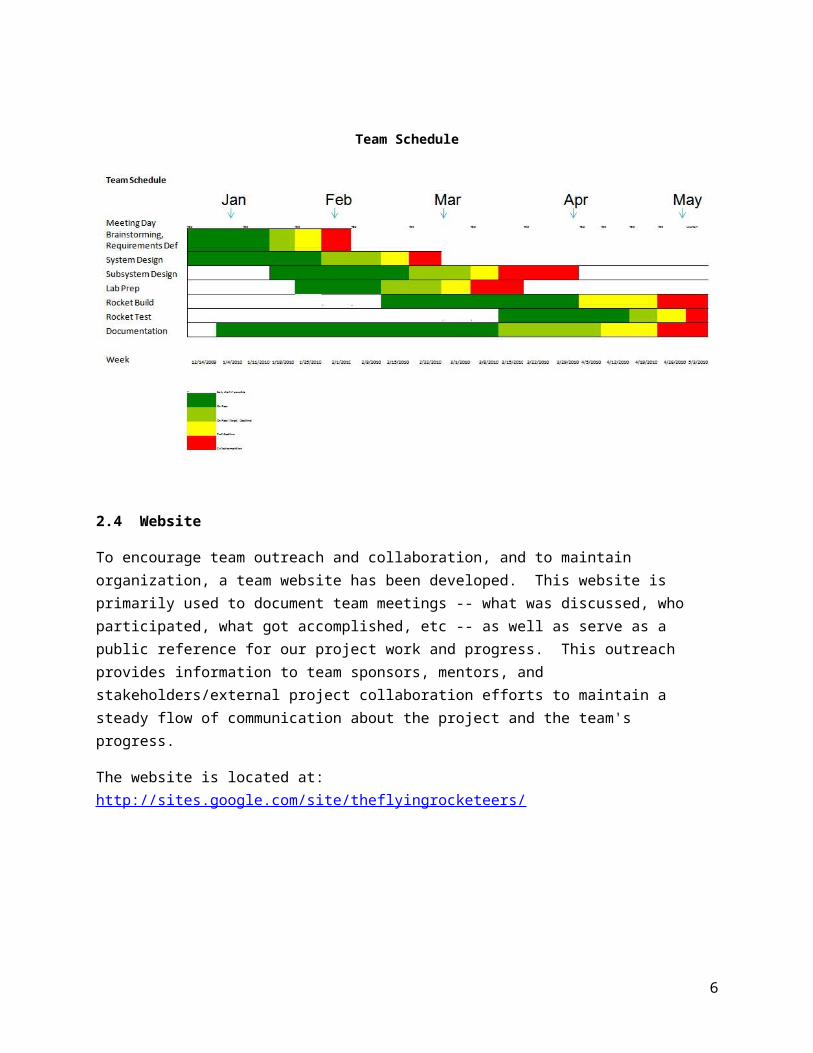
2.3 Team Schedule
To ensure timely and complete delivery of each rocket subsystem, a Work Breakdown Structure (WBS) for the project was developed, detailing all individual tasks that need to be completed for each system and subsystem of the rocket and project. The WBS was then used to generate a draft schedule for the project as described below:
3

Team Schedule
2.4 Website
To encourage team outreach and collaboration, and to maintain organization, a team website has been developed. This website is primarily used to document team meetings -- what was discussed, who participated, what got accomplished, etc -- as well as serve as a public reference for our project work and progress. This outreach provides information to team sponsors, mentors, and stakeholders/external project collaboration efforts to maintain a steady flow of communication about the project and the team's progress.
The website is located at: http://sites.google.com/site/theflyingrocketeers/
4

Team Website Screenshot
5
2.5 Lab, Tooling, Equipment, Parts Manufacturing Support
The Flying Rocketeers conduct meetings and rocket assembly within a dedicated lab on the Boeing Huntington Beach campus. The lab was issued by Boeing Facilities and is located within former ULA (United Launch Alliance) workspace, and includes a ventilation hood as well as assembly space.
Rocket Team Members Discussing Design
Additionally, the Boeing Young Engineers Team (BYET) has provided for use of their lab space and tooling equipment (also on the Boeing HB campus) for rocket parts construction and testing. Similarly, the Composites Manufacturing lab has offered support for carbon fiber shaping and hardening, as well as donating aerospace grade raw materials for composite body tube construction. A paint booth is also available for the team’s use, located near the BYET lab.
6

2.6 Mentoring/Management Support Accomplishments
Early project efforts included preparation of informational and marketing material for distribution to various site and business unit executives. The introductory briefing includes the project overview, goals, team roster, integrated rocket conceptual design, schedule, and project costs.
Initial interest was expressed with Huntington Beach site Manufacturing Development organization for project sponsorship and an informal meeting was held with the site director. The strategy to support the project will be similar to previously sponsored Boeing projects, which includes technical, manufacturing, tooling, and area support. The go-forward plan is to brief the Huntington Beach site chief engineer with the detailed plan and request for help. Various mentorships from the engineering organization have been established, which includes experts from materials processing to structural concepts. Excess materials for hardware construction were also offered to the project.
The next steps include:
To continue to solicit to the engineering business unit for support, in terms of funding and mentorship.
To continue to develop project visibility with the executive management and other communication organization
To have either the manufacturing operations or engineering organization to host a composites workshop for the project team members to develop hands on experience.
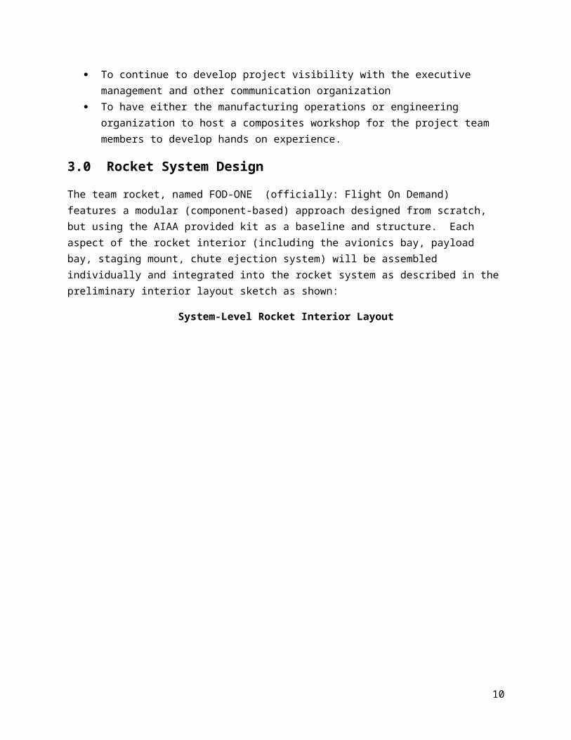
3.0 Rocket System Design
The team rocket, named FOD-ONE (officially: Flight On Demand) features a modular (component-based) approach designed from scratch, but using the AIAA provided kit as a baseline and structure. Each aspect of the rocket interior (including the avionics bay, payload bay, staging mount, chute ejection
7

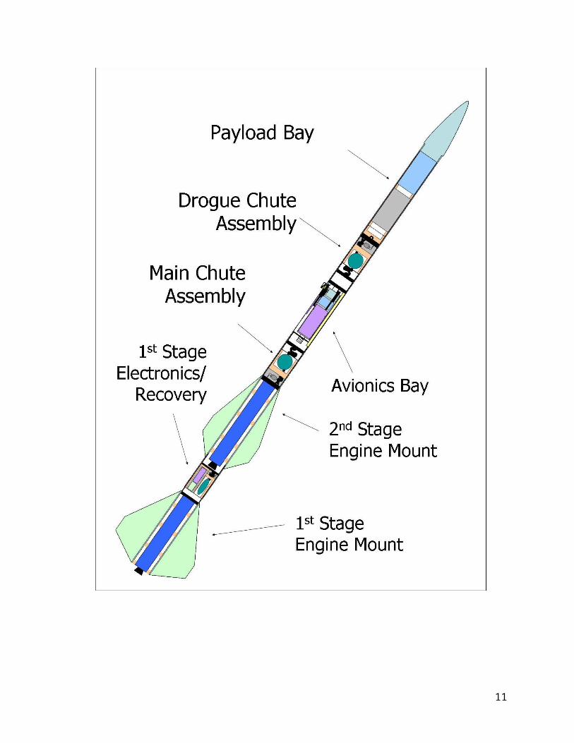
system) will be assembled individually and integrated into the rocket system as described in the preliminary interior layout sketch as shown:
System-Level Rocket Interior Layout
8

First and Second Stages Design Layout
The rocket system is comprised of the following components:
1. First stage control systema. The lower stage control features a self-powered controller designed to detect launch
and apogee, deploy the first stage recovery chute, and activate a beacon for easy recovery. The first stage also includes a digital signal to ping the main (second stage) controller periodically to indicate it is enabled and the recovery system is standing by. For more information about the first stage controller, see Section 3.3.
2. First stage recovery system
9
a. The lower stage features a parachute ejected by a black powder combustion chamber located beneath the parachute ejection assembly. The ejection is initiated by the first stage control system when it has detected apogee, and includes redundant (independently activated) igniters for redundancy. Additionally, a beeper is enabled to aid in the recovery of the stage.
1st Stage Electronics and Recovery Subsystem Layout
3. Avionics Baya. The avionics bay includes all electronic systems used to control second stage ignition
and recovery events. The bay includes a 11.1V lithium-polymer battery (2100 mAh), Power Distribution board (PDB) used to distribute relay power and regulate voltage, an external 2.4 Ghz wireless camera assembly for immediate visual feedback to ground, a controller (described below), a flight data recorder + 900 Mhz long-range transmitter for telemetry feedback and sensor data recording (including G-forces, fin strain, temperature, 2-axis acceleration, and GPS), and a wiring harness used to distribute
10
power to the chute ejection squibs and 2nd stage igniters located throughout the rocket body.
b. The upper stage control features an integrated controller designed to start all second stage ignition and recovery events, including the 2nd stage ignition delay timing, redundant ignition of the second stage engine, sensor data collection, altitude detection, drogue chute deployment, and main chute deployment. The controller is used to activate higher voltage relays to start ignition sequences of the 2nd stage engine, drogue, and main chute black powder squibs, and outputs event and fault status to the data recorder for telemetry downlink. The electronics bay is self contained and designed to screw in directly to the 2nd-stage mid bulkhead, and align with the wiring harnesses for ease of integration (as shown in the figure below) .
Rocket Avionics Subsystem Layout
4. Drogue/Main Chute Assemblya. The drogue and main chutes are situated in the lower and mid areas of the rocket’s
upper stage (above and below the avionics bay, respectively). The assembly is comprised of a pressure-isolated expansion chamber containing two redundant black powder squibs and their igniters. The parachutes are anchored to the rocket bulkheads above and below the assembly, and are housed within a container which will eject the chutes outward when the squibs are ignited. The rocket body is designed to slide out and separate at these locations.
Parachute Subassembly Layout
11

5. Payload Bay Assemblya. The payload bay is a fully contained area located at the top of the rocket, below the
nosecone, and is used to contain the competition payload as well as the delivered high school payload. To account for the size range of both payloads, an insert will be designed to rest on the upper bulkhead to keep the payload as close to the nosecone as possible (to leverage a higher center of mass).
12

Payload Bay Layout
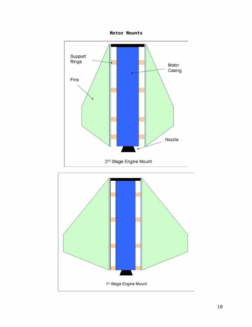
6. Engine mountsa. Both lower and upper stage engine casings will accept the reloadable 6-G and 6-GXL
motor casings issued for the selected engines. A design is currently in work to allow the motor casings to be removed if necessary (lessons learned from 2009 launch competition).
13

Motor Mounts
14

3.1 Mass Budget
One of the most important initial trade studies conducted by the team was to determine the rocket mass budget. This budget was developed to constrain mass distribution among subsystems and to serve as a starting point for trajectory and altitude analysis. Two approaches were taken to generate a suitable mass range for the rocket system:
- A bottom-up approach, where critical/mandatory rocket component masses were estimated to generate a minimum feasible system launch weight and subsystem weight. From here, the mass was distributed into the rocket body as required and modeled to determine if the center of gravity (Cg) was in an appropriate spot to keep the rocket stable.
- A top-down approach, where the team set G-loading constraints and velocity limitations, provided inputs (target altitude and an experimental mass estimation), and analyzed the thrust output of each engine available for use in the competition to determine if a the system mass range could be could be and converged upon. From this approach, we were required to modify our inputs (lowering altitude or scaling our mass target range, for instance) to adhere to the set constraints and limitations.
The constraints set in the top-down approach described above are derived from rocket design research and team member backgrounds/experience. The team determined that the optimal G-loading during stage burn should range between 5-8 G's. Too high, and the rocket will accelerate too quickly and could damage components or reach higher than desired speeds. Too low, and the rocket will not leave the guide rail fast enough to stay aligned vertically in flight before it reaches a self-stabilizing air speed. Also, a speed limitation of Mach 0.8 was developed in order to avoid compressive flow, which will result in much higher drag and the potential for flutter or high flight turbulence. Analysis was then performed to determine the correct mass distribution (between the first and 2nd stages) to not only keep the rocket within the defined constraints during each individual burn, but also optimized to maximize flight altitude.
Below is a flowchart detailing the algorithm used to generate the mass budget from the top-down approach.
15

Mass Budget Trade Study: Top-Down Approach
Through both analysis methods, an initial mass range estimate was developed and then distributed to each subsystem as needed. Based on the required minimum subsystem mass (as determined from the bottom-up analysis approach), subsystem positioning within the rocket body was determined to keep the center of gravity as high in the body as possible (and thus, moving the Cg further from the rocket's center of pressure -- Cp -- to ensure stability and reduce fin size to lower drag).
The current mass budget defines an acceptable loaded (rocket + payload + motor grains) final weight between 32 and 40 lbs, with a "sweet spot" of 36 lbs to maximize altitude. If the final rocket weight is below 35 lbs, a different set of engines would need to be chosen than were selected in Section 3.3. A
16

maximum rocket weight below 40 lbs ensures the G-loading stays above our 5 G minimum burn acceleration threshold.
Current Mass Budget Estimation
Item Quant Weight (lbs)Structure (2nd Stage) 1 9.5Structure (1st Stage) 1 3.5
Avionics Bay 1 3.5Payload Allocation 1 7.0
Engine Casings + Engines 1 9.0Parachute Assemblies 2 3.5
1st Stage Controller Bay 1 2.5TOTAL 38.5
3.2 Carbon Fiber Composite Reinforcement
To structurally reinforce the competition-provided cardboard kit, the team has chosen heat-treated carbon fiber-epoxy composite as the primary rocket body and fin reinforcement material. Epoxy-coated cardboard is light weight and is strong when a force is applied length wise to the laminate, but will tear easily when exposed to a shearing force. Also, cardboard tubing can easily absorb moisture and weaken, resulting in a severely degraded compressive load tolerance. Also, cardboard is also very flammable and will be exposed to high temperatures during squib firing.
Carbon fibers reinforcing a stable matrix of epoxy
Carbon fiber composites are light weight since the resin is low density, but exhibit a very high tensile strength (which can be optimized to improve stress tolerance along specific directions on the rocket's external structure based on the carbon fiber layering pattern, thickness, and treatment method). Metallic reinforcement has been considered, but the excessive weight required from a higher-density metal would exceed mass requirements for the body based engines the team has chosen. Carbon fiber has a greater strength to weight ratio than metals and also has a high stiffness to weight ratio. Carbon
17
fiber composites have some interesting characteristics that aren’t common in metals; metals deform when exposed to high heat and stress and will retain the deformation (due to a low material yield strength). In some cases, this is necessary to support form fitting. However, deformed metal will be severely weakened and may compromise the structural integrity of the entire rocket body. Carbon fiber composites are more brittle, but will not deform when exposed to high-speed stresses during the rocket's flight. Additionally, the surface finish of the carbon fiber composite is smooth and will create very little surface drag on the rocket body.
The following trade study comparison chart indicates that carbon fiber with a core has better stiffness to weight properties than solid carbon fiber. This is an important factor when reinforcing the rocket fins and to prevent large bending moments on the fin from deforming at high speeds, which could result in instability, flutter, and possibly catastrophic failure. The chart compares other important properties of carbon fiber with different cores.
Rocket Fin Core Strength Comparison
COMPARISON CRITERIA
PRODUCTS Stiffness to Weight
Toughness
Crushability
Moisture Resistance
Sound Absorbency
Solid Carbon Fiber GOOD GOOD BEST BEST POOR
Birch Core BETTER BEST BEST GOOD POOR
Balsa Core BETTER GOOD BETTER POOR GOOD
Polypropylene Honeycomb Core BEST GOOD GOOD BEST BEST
Nomex Honeycomb Core BEST BETTER BETTER BETTER BEST
Depron Foam Core BETTER POOR POOR BETTER BETTER
Airex Foam Core BEST GOOD GOOD BETTER BETTER
Divinycell Foam Core BETTER BEST BETTER BETTER GOOD
18

3.3 Rocket Engine Selection
The primary driver of the overall rocket performance is the motor selection. The table below lists all of the parameters of the motors that are allowed as part of the AIAA rocket design challenge rules. All of this information was compiled and made available on the WinROC website http://www.drmoore.org/.
An additional performance factor “T/W” (Thrust to Weight Ratio) was computed from the total impulse and the total weight of each motor. To show the range of values for each parameter, the following tables show the minimum and maximum values and the motor that corresponds to that value for each motor property.
Max Values for Each Motor Property
Min Values for Each Motor Property
19
DESIG MFG T/WL1030 2,775K1440 2,168K270 7.48L1030 2.34L1030 1.52K590 1,368
TOT ISP
PEAK
BURN
TOT WGT
FUEL WGT

Our Key Performance Parameters (KPP) driving our motor selection rocket design (in order of decreasing priority) are as follows:
1. Maintain maximum sustained ( > 0.1 sec) acceleration below 8 Gs and minimum sustained burn duration (>3.0 sec) above 5 Gs
2. Maintain maximum velocity below Mach 0.83. Maximize Rocket peak altitude
Our initial design iterations involved using an L-class motor for the first stage and a K-class for the second stage. To meet KPP#2 our K-motor would ideally have a lower peak thrust and also have a high total-impulse for KPP#3. This resulted in the approximate ideal design space on the Peak Thrust to Total Impulse plot and drove the engine selection of the K-660. The parameter variation on the L-class motors for the rocket first stage was much narrower than the K-class motors. The design space for the L-motors was not bounded by KPP#2, and therefore KPP#3 selected maximum total impulse that met the constraint of KPP#1 – motor L1030.
20
DESIG MFG T/WK675 2,016K270 440K1440 1.65K590 1.72K590 0.96K828 933
TOT ISP
PEAK
BURN
TOT WGT
FUEL WGT

The motor clearly meeting KPP 1 and 3 was the K660. The K660 first stage achieved the highest altitude (7279.8ft) and minimum max. acceleration (7.0 Gs).
21
1,800 2,000 2,200 2,400 2,600 2,800 3,0000
500
1,000
1,500
2,000
2,500
K675
K270
K828
K1275
K815
K750
K590K820
K1440
K700K660
K1050L640L990
L730
L1030
f(x) = 1539.32 ln(x) - 10612.34R² = 0.17
Solid Rocket Motor Thrust Comparison
Column CLogarithmic Regression for Column C
Total Impulse
Pea
k Th
rust
2,740 2,745 2,750 2,755 2,760 2,765 2,770 2,775 2,7801,000
1,100
1,200
1,300
1,400
1,500
1,600
1,700
L640
L990
L730
L1030
f(x) = -8859.96 ln(x) + 71665.1R² = 0.06
Solid Rocket Motor Thrust ComparisonL-class High Impulse detail
Column CLogarithmic Regression for Column C
Total Impulse
Pea
k Th
rust
Stage1 K-motor ideal design space
Stage2 L-motor ideal design space

22

As predicted by the design space selection on the second stage, the optimum second stage motor is indeed the L1030 as shown by the second stage L-motor comparison below.
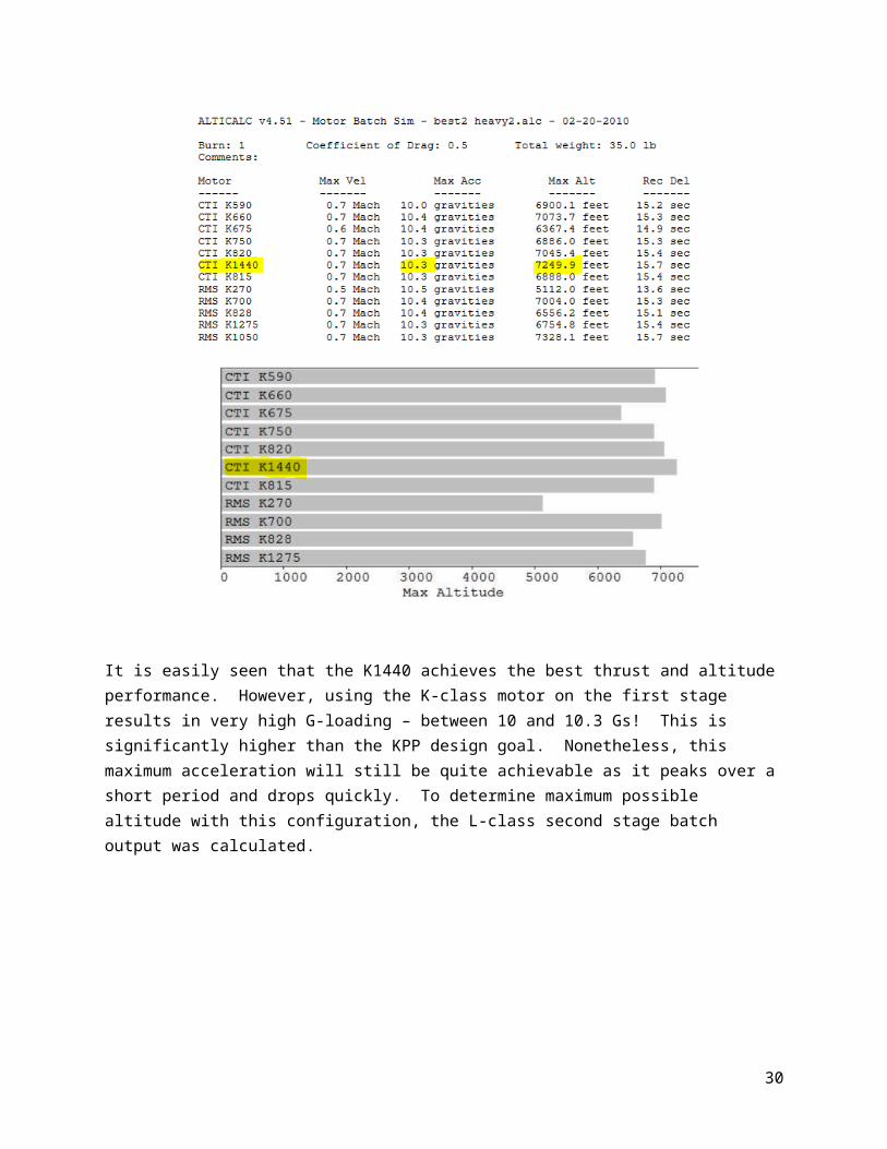
The alternative design is the swapping of the stage motor classes – a K-motor 1st stage and L-motor 2nd stage. This was theorized to provide more of the total impulse when the rocket is already at speed. Of course swapping the motors means that the motor selection will be completely different. The AltiCalc output below shows the relative comparisons between all of the K-class motors mounted on the first stage with a fixed L-class second stage.
23

It is easily seen that the K1440 achieves the best thrust and altitude performance. However, using the K-class motor on the first stage results in very high G-loading – between 10 and 10.3 Gs! This is significantly higher than the KPP design goal. Nonetheless, this maximum acceleration will still be quite achievable as it peaks over a short period and drops quickly. To determine maximum possible altitude with this configuration, the L-class second stage batch output was calculated.
24

On the opposite end of the L-class spectrum, the L640 turns out to be the best choice for a stage 2 motor.
Motor Selection SummaryIn summary, the optimum configuration is:
1st Stage 2nd Stage Max Acceleration Max Altitude
Configuration 1: L1030 K660 7.5 G 7279 ft.
Note that these altitude predictions are preliminary and based on the worst-case total weight of the rocket (in excess of 40 lbs empty including payload). The design goal is currently 26 lbs empty weight including payload, which meets the G-loading constrictions stated above and maximizes altitude of approx 10,000-12,000 ft.
See Appendix A for the full data plots detailing the whole flight profile, with the two configurations discussed above displayed as bold lines in the plots.
25

3.4 Control System Overview
Our team chose to design our own control system rather than buy one off the shelf. This option offered us the greatest flexibility and opportunity for creativity and education. We chose two processor development boards to be the basis for our control system, one for each stage.
The first stage control system will be based on an Allen LAB PRO-51 8051 development board. This board has a simple 8051 processor and sufficient I/O for the first stage control. It can be programmed in Assembly or C using the C51 version of the Keil tools. This controller will be responsible for detecting launch, detecting first stage separation, detecting first stage apogee, deploying first stage parachute, initiating recovery beacon, and logging sensor inputs. We anticipate needing to incorporate G-force and altitude sensors with this control board, along with many relays to initiate events.
Allen LAB PRO-51 8051 Development Board
The second stage control system will be based on an Olimex LPC2148 ARM development board. This board has a more complex ARM processor that includes many built in peripherals. The peripherals we plan on taking advantage of include digital to analog converters, analog to digital converters, Secure Digital memory card interface, and Universal Asynchronous Receiver/Transmitter interfaces. The LPC2148 can be programmed in C using the ARM version of the Keil tools. This controller will be responsible for detecting first stage separation, igniting second stage motor, detecting if ignition was successful, deploying drogue chute at apogee, deploying main chute at desired altitude, detecting chute deployment, logging all sensor input, and controlling all redundant systems. This stage will also need G-force and altitude sensors and relays.
Olimex LPC2148 ARM Development Board
26

We have laid out the series of events and stimulus for these events in a flowchart as seen below. This flowchart provides an algorithm to allow us to design our software and simulate it using Keil tools. We will also construct a hardware test bed by replacing inputs to the controller boards with switches and outputs with LEDs and oscilloscopes. Once the rocket is built we will run as many live tests as we can to ensure full rocket redundancy, safety, and launch success.
In the flowchart below, the trapezoids represent sensor inputs to the controller, the flags are outputs (to our telemetry system or recorded), and the boxes are controller internal functions (such as keeping time or reading inputs) and external functions (such as switching a relay – starting an igniter).
27

Second Stage Controller Logic Algorithm
28

29
One of the important outputs will be an analog event indicator – our telemetry system accepts an analog input which we can use to read "flags" from the controller to tell us what stage we are in or if something went wrong. This will be important to help troubleshoot problems we can’t necessarily see from the ground to help with future designs.
3.5 Telemetry System Overview and Test Plan
One of the AIAA competition goals is to model the rocket flight path as accurately as possible, and compare the simulated/modeled results to the actual results post launch. To meet this goal the Eagle Tree wireless telemetry system was purchased. The system runs on the 900 Mhz band and is capable of providing live feedback of the rocket's GPS, altitude, velocity, and other sensor data to our ground station in real-time with a range of several miles using a high-gain antenna. It also has the ability to log data throughout the flight and store it in the event that communication with the ground station is lost. Sensors purchased to be used with the Eagle Tree system are temperature, altitude, accelerometer, GPS, and velocity sensors, additional sensors can be added to the system.
The Eagle Tree wireless hardware components and a panel from the software used for data recording are. The high-gain yagi antenna for the ground station also is shown.
30

To ensure that the Eagle Tree wireless telemetry system meets the project's requirements testing was done on the Eagle Tree system and the additional sensors. Redundancy in the design allows live/manual actions from the ground to override any autonomous actions in case of failures or anomalies. Preliminary tests were performed that verified the real-time telemetry from the sensors and radio worked. For these tests the smaller antenna that came with the Eagle Tree was used and the data recorder was connected directly to the computer. All sensors were zeroed out using the included software prior to testing. The panels showing live data, in Figure 3, display accelerometer, temperature, and GPS data with normal refresh rates. Observations were recorded for each of the sensors. For the accelerometer sensor, the accelerometer panel displays a minimum and maximum range from -3G to +3G, whereas the data recorded and outputted text will show the actual values with a greater range. For the temperature sensor, the data seems accurate but there is a slow update rate of 1 Hz. The GPS sensor was unable to acquire a signal with both the small antenna and larger yagi antenna. Further tests will be done to determine the length of time it takes the GPS sensor to acquire a signal as well as its accuracy.
31

Range tests were performed on the data recorder to verify the range would be sufficient for the launch so that live data can be recorded and redundant systems can be manually activated if necessary. The data recorder performs when it is connected directly to a computer, however to connect remotely the battery and power regulator connections had to first be modified to work properly because the connectors for each were incompatible. Soldering was done on the wires from the battery and a new connector was attached allowing it to connect to the power regulator. Preliminary range tests were performed using the yagi antenna on the ground at the Boeing, Huntington Beach facility in Huntington Beach, California. The test plan included steps for long range tests using the Yagi antenna at a series of angles to determine the best angle for the antenna during launch in order to minimize losses of communication between the rocket and the ground station.
Material tests were performed to determine the best material for the main body of the rocket while providing the best communication to the ground station and allowing the GPS sensor to acquire and lock onto a signal. Different materials such as aluminum, composites, and fiberglass with varying thicknesses were used to determine the interference of each material with the data recorder to the yagi antenna, the GPS sensor's ability acquire and lock onto a signal, and the accuracy of the data from the GPS sensor.
During both preliminary range and material tests, the weather disrupted all testing and data recording was unsuccessful. Further ground tests will be performed to determine the range of the yagi antenna and the material for the main body of the rocket. Another factor that may have attributed to the unsuccessful preliminary tests was that there may have been too much interference from the ground for the data recorder. During the next round of testing the data recorder might be elevated, by going to a high place such as on top of a building, to reduce the amount of interference from the ground.
3.6 Modeling Approach
3.6.1 Preliminary Design Phase
One of the first steps into rocket design is to develop a conceptual idea of the mission profile. Once this is accomplished, a more detailed rocket design can be established, such as: staging, engine size, types of payloads, and recovery systems. For this particular project set constraints were given by the director of the event. One of this constraints was to use type L and K engines, and a specify diameter for the rocket body. Therefore, the team determined, based on preliminary analysis, that a maximum altitude of an approximately 10,000-12,000 ft was achievable necessary in order to record as much data of the flight needed to study the overall rocket performance. In addition, this altitude was set as a challenge for this team base on the power provided from both engines. The following figures show the type of engines that will be used to power the first and second stages of the rocket on launch date.
32

Specifications of the Cesaroni L1030 Rocket Engine (1st Stage)
The following figure shows the type of engine that will be used to power the second stage on launch date.
Specifications of the Cesaroni K660 Rocket Engine (2nd Stage)
In addition to the trade studies conducted to determine the propulsion system that will be used by this team, the overall rocket layout architecture was analyzed to ensure a stable rocket mass and pressure distribution (varying the internal positions of payloads, parachutes, the avionics bay, and fin sizes impacted these locations greatly). To aid in this design phase, a very used useful tool called “RockSim” (developed by Apogee Components) was used to provide preliminary analysis on rocket stability and aerodynamic performance. This simulation software was used to help predict the rocket body's center of pressure (Cp) and center of mass (Cm) for first and second stage individually as well as the overall Cp
33

and Cm. The following figure shows a graphical representation of the overall layout of the different sections of the rocket design.
Full Rocket Main Architecture
In addition to the overall representation of the rocket design, it is important to describe the second stage as a standalone design. As a result that second stage houses the most important payloads and the flight computers. The following figure shows a graphical representation of the second stage layout ad specifications.
Second Stage Main Architecture
Once all the simulated design was complete, the next step was design start to design the rocket entirely in a 3D CAD models. The main purpose for this detail design was to develop a better understanding of all the systems (externally and internally) and to determine the most effective interface when it came time to assemble of the overall architecture. The following figure represents the preliminary conceptual design of the rocket structure. This is an evolutionary process that will reach a higher level of design details in the upcoming weeks.
Preliminary 3D model of the Rocket Design
34

35

Appendix A -- Motor Analysis
36
0
1000
2000
3000
4000
5000
6000
7000
0 2 4 6 8 10 12-4
-2
0
2
4
6
8
10
best2 L1030 K 660 36.44lbs 6 in. dia.best2heavy L1030 K 660 44.44lbs 6 in. dia.L1030 K 675 44.42lbs 6 in. dia.B est#3 - 7300ft inverted with K 1440 first stge L640 second K 1440 L640 44.10lbs 6 in. dia.B est3 with tweak 1 sec delay tim e K 1440 L640 44.10lbs 6 in. dia.

37
5000
5500
6000
6500
7000
7500
8000
8500
13 14 15 16 17 18 19 20 21 22 23 24-1.8
-1.7
-1.6
-1.5
-1.4
-1.3
-1.2
-1.1
-1
-0.9
-0.8
best2 L1030 K 660 36.44lbs 6 in. dia.best2heavy L1030 K 660 44.44lbs 6 in. dia.L1030 K 675 44.42lbs 6 in. dia.B est#3 - 7300ft inverted with K 1440 first stge L640 second K 1440 L640 44.10lbs 6 in. dia.B est3 w ith tweak 1 sec delay tim e K 1440 L640 44.10lbs 6 in. dia.

Matlab Code Generated for WinROC Data Integration “rocmenu.m”
38

39

Appendix B -- Initial Rocket Layout Sketch
40