The FlipClock An accelerometer-controlled digital clockmicrocontrolled.com/The FlipClock...
10
The FlipClock – An accelerometer-controlled digital clock Introduction: One of those things you dread about morning is waking up to a blaring alarm clock, and fumbling sleepily around for the off switch. Have you ever wished there was a simpler way to turn it off? I’ve come up with a solution to this annoying problem: The FlipClock! The FlipClock is an accelerometer- controlled alarm clock, meaning it can sense its position on a three axes. To turn it off, all you have to do is knock it over on its back. On the weekends when you want to sleep in, simply flip it over the night before. The digits on the clock will automatically readjust and the clock will display the “Off” indicator. If you want to change what time the clock will wake you up, set it up on its side until the colon stops blinking, then tilt it back and forth to scroll through the time. When you are done, lay it back down and it will save your changes. Hardware: The FlipClock uses a Propeller Chip by Parallax as its microprocessor, and includes the supporting hardware (EEPROM, 5.000 MHz Xtal). To keep time it uses a GPS module that communicates with the Propeller via a serial interface. This is major overkill for a digital clock, so I’ve also written the code to work with a DS1302 RTC (Real Time Clock) IC. The alarm itself is just a speaker amplified with a transistor. The Propeller Chip is powered by a 3.3V regulator and the speaker by a 5V regulator (see BOM for parts numbers). The power is supplied by a wall transformer (“wall wart”). The accelerometer is a 3AD module by Rayslogic.com and is the magic piece of the device. It communicates with the Propeller using I2C protocol and shares the same pins as the I2C boot EEPROM. The four-segment LED display used for displaying the time is driven directly by the Propeller without any LED driver chip or shift register. This presented problems at first as the massive current draw by the LEDs would overheat the regulators and trigger the Propeller’s brownout protector, resetting the chip. This seemed to happen only when the alarm would go off, which would pull even more current, as the speaker is a direct connection to the 5V regulator. I eventually fixed this persisting problem by lowering the input voltage from 12V to 6V and using regulators with larger heatsinks. The PCB is the lower half of a Parallax Prototyping board that has been cut to fit the enclosure, which is a Hammond Manufacturing 1591 series. The only modifications to the enclosure are a large hole for the speaker, a small hole for the power jack, and the square hole in the lid for the display. I used thin (28 AWG) compound wires to connect the LED display to the Propeller chip setup because they are small and flexible. However, I offer a word of warning to those who do this: the solder joint creates a bending point where the wire will bend and weaken every time you take the lid off to reprogram it or modify the circuitry. This caused a lot of trouble for me, as I would screw the lid back on only to find that one of the digits wasn’t lit and the wire had snapped. Then I
Transcript of The FlipClock An accelerometer-controlled digital clockmicrocontrolled.com/The FlipClock...

The FlipClock – An accelerometer-controlled digital clock
Introduction:
One of those things you dread about morning is waking up to a blaring alarm clock, and
fumbling sleepily around for the off switch. Have you ever wished there was a simpler way to
turn it off? I’ve come up with a solution to this annoying problem: The FlipClock! The FlipClock
is an accelerometer- controlled alarm clock, meaning it can sense its position on a three axes.
To turn it off, all you have to do is knock it over on its back. On the weekends when you want to
sleep in, simply flip it over the night before. The digits on the clock will automatically readjust
and the clock will display the “Off” indicator. If you want to change what time the clock will
wake you up, set it up on its side until the colon stops blinking, then tilt it back and forth to
scroll through the time. When you are done, lay it back down and it will save your changes.
Hardware:
The FlipClock uses a Propeller Chip by Parallax as its microprocessor, and includes the
supporting hardware (EEPROM, 5.000 MHz Xtal). To keep time it uses a GPS module that
communicates with the Propeller via a serial interface. This is major overkill for a digital clock,
so I’ve also written the code to work with a DS1302 RTC (Real Time Clock) IC. The alarm itself is
just a speaker amplified with a transistor. The Propeller Chip is powered by a 3.3V regulator and
the speaker by a 5V regulator (see BOM for parts numbers). The power is supplied by a wall
transformer (“wall wart”). The accelerometer is a 3AD module by Rayslogic.com and is the
magic piece of the device. It communicates with the Propeller using I2C protocol and shares the
same pins as the I2C boot EEPROM. The four-segment LED display used for displaying the time
is driven directly by the Propeller without any LED driver chip or shift register. This presented
problems at first as the massive current draw by the LEDs would overheat the regulators and
trigger the Propeller’s brownout protector, resetting the chip. This seemed to happen only
when the alarm would go off, which would pull even more current, as the speaker is a direct
connection to the 5V regulator. I eventually fixed this persisting problem by lowering the input
voltage from 12V to 6V and using regulators with larger heatsinks. The PCB is the lower half of a
Parallax Prototyping board that has been cut to fit the enclosure, which is a Hammond
Manufacturing 1591 series. The only modifications to the enclosure are a large hole for the
speaker, a small hole for the power jack, and the square hole in the lid for the display. I used
thin (28 AWG) compound wires to connect the LED display to the Propeller chip setup because
they are small and flexible. However, I offer a word of warning to those who do this: the solder
joint creates a bending point where the wire will bend and weaken every time you take the lid
off to reprogram it or modify the circuitry. This caused a lot of trouble for me, as I would screw
the lid back on only to find that one of the digits wasn’t lit and the wire had snapped. Then I

would have to open back up and remove everything from the enclosure to solder it back on. To
others thinking about doing this, I would suggest using a ribbon cable.
Software:
The source code for this project is written for the Propeller chip as a .spin file. It uses the
GPS_Float, DS1302_Full, PSB_I2CDriver, and NS_sound_drv_051_22khz_16bit objects. The
program initializes the objects then starts a cog, or processor, that runs the LED display. After
this it goes into the main loop, this is the main part of the code:
x:=i2c.GetAccelX8 y:=i2c.GetAccelY8 if x > 0 and x < 100 outa[13..14] := %10 if hour == alarmhour and minute == alarmminute ifnot alarmflag == "!" ns.start(22) repeat 500 ns.PlaySoundFM(0,ns#SHAPE_TRIANGLE,3000,ns#DURATION_INFINITE,255,$2457_9DEF) waitcnt(clkfreq/4 + cnt) ns.StopSound(0) waitcnt(clkfreq/4 + cnt) x:=i2c.GetAccelX8 if x < 10 quit ns.Stop alarmflag := "!" oldmin := minute ifnot oldmin == minute alarmflag~ if hour > 12 hour -= 12 decInverted(minute,0) decInverted(hour,2) if x < 0 or x > 100 outa[13..14] := %01 if hour > 12 hour -= 12 dec(hour,0) dec(minute,2) waitcnt(clkfreq + cnt) !outa[12]
I have excluded the function that sets the alarmhour and alarmminute variables as well as the
one that gets the time from the GPS, as these are not as important as this code. It starts out by
loading the x and y variables with the position the clock is in on 2 axes. There is a third axis, the
z axis, that is not used in this project. First it checks if the clock is right side up or inverted
relative to the accelerometer. If it is inverted, then the alarm “On” indicator light is turned on
and it checks if the current time matches the alarm time. If it doesn’t, it displays the inverted

digits. If it does, it starts the sound driver and enters a loop where it blasts a tone out the
speaker repeatedly. It checks the X position of the accelerometer until it detects that the device
has been knocked over, then it exits the loop.
If the device was not inverted, it never checks for the alarm, it just displays the upright digits
and shows the “Off” indicator.
How to build it:
If you want to build your own, here are instructions on how. Use the schematic, Figure 2, for
reference.
Figure 2:

Step 1: Build a working Propeller Chip setup. This consists of a Propeller Chip, EEPROM, 5.000
MHz Xtal, 10k resistor, and a power source. See the BOM for more information. I constructed
the Propeller setup from scratch on a trimmed down blank Parallax Prototyping board, but if
you wanted to save the time and risk of building one yourself, you could trim down a Propeller
Protoboard the same way you would do the blank one; however, I have no guarantee that this
works. Parallax makes the boards to stack on each other so both are the same size and you
should be able to cut both the same way. Figure 1 shows what the finished board looks like.
Figure 1:
As you can see from the photo the top and side of the board has been cut off and the edges on
the right have been sanded down. This modification is of course unnecessary if you are
planning on using a larger enclosure. Solder in the DIP-40 and DIP-8 IC sockets for the Propeller
and EEPROM. Use Figure 1 and the schematic (Figure 2) as a guide to assemble the rest. Keep in
mind that there are power and ground rails on each side of the blank Prototyping board but not
on the Propeller protoboard. Remember to solder down the programming header or you won’t
be able to program the Propeller. If you used the Propeller protoboard, skip to the next step.
Otherwise, you will need to install the power system. Since you can’t see the setup I have in
Figure 1, here’s how to position them on the board. Fold down the pins, then face them
towards each other, so that the heatsinks are facing out. Set them at the top of the board and
solder them down with one space between them (when I say “space” I am referring to rows of
through holes). Drill holes in the board underneath the ones in the heatsinks and attach the
heatsinks to the board with small machine screws. Place the decoupling capacitors to each side
of the regulators and solder them down. Now connect the circuit as shown in the schematic
(Figure 2). The pinout for the regulators in shown in Figure 3.
Figure 3
When you are done, plug in Prop Plug if you have one, and test it with Propeller Tool (Press F7).
It should find the Propeller without any trouble.
Step 2: Install the timekeeper. You can choose between the easiest to use or the cheapest
solution. I went with the GPS, which is the easiest, although I also installed the cheaper RTC on
the board for demonstration. If you want to install the GPS module (see the BOM for parts
numbers) wire up the color-coded red and black wires to the 3.3V power and ground rails , the
blue wire to pin 21, and the yellow wire to pin 20. If you went this route, skip to the next step,
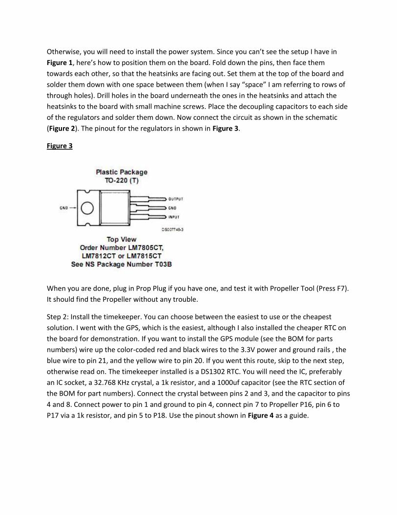
otherwise read on. The timekeeper installed is a DS1302 RTC. You will need the IC, preferably
an IC socket, a 32.768 KHz crystal, a 1k resistor, and a 1000uf capacitor (see the RTC section of
the BOM for part numbers). Connect the crystal between pins 2 and 3, and the capacitor to pins
4 and 8. Connect power to pin 1 and ground to pin 4, connect pin 7 to Propeller P16, pin 6 to
P17 via a 1k resistor, and pin 5 to P18. Use the pinout shown in Figure 4 as a guide.
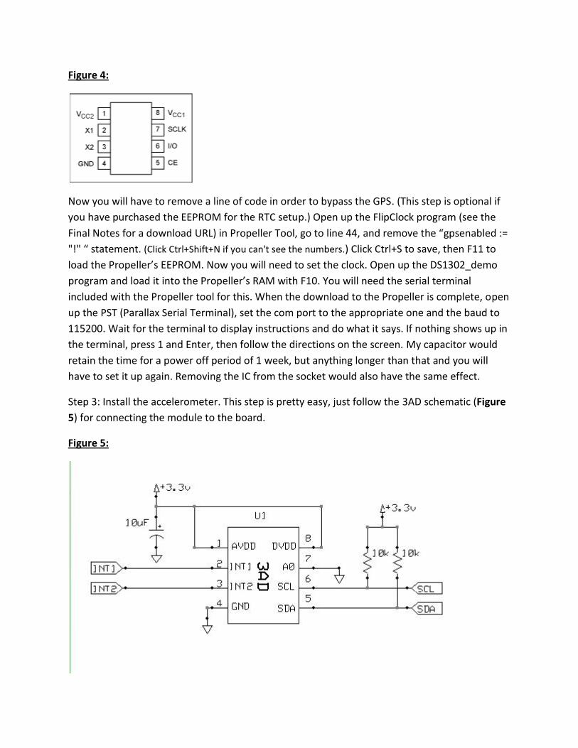
Figure 4:
Now you will have to remove a line of code in order to bypass the GPS. (This step is optional if
you have purchased the EEPROM for the RTC setup.) Open up the FlipClock program (see the
Final Notes for a download URL) in Propeller Tool, go to line 44, and remove the “gpsenabled :=
"!" “ statement. (Click Ctrl+Shift+N if you can't see the numbers.) Click Ctrl+S to save, then F11 to
load the Propeller’s EEPROM. Now you will need to set the clock. Open up the DS1302_demo
program and load it into the Propeller’s RAM with F10. You will need the serial terminal
included with the Propeller tool for this. When the download to the Propeller is complete, open
up the PST (Parallax Serial Terminal), set the com port to the appropriate one and the baud to
115200. Wait for the terminal to display instructions and do what it says. If nothing shows up in
the terminal, press 1 and Enter, then follow the directions on the screen. My capacitor would
retain the time for a power off period of 1 week, but anything longer than that and you will
have to set it up again. Removing the IC from the socket would also have the same effect.
Step 3: Install the accelerometer. This step is pretty easy, just follow the 3AD schematic (Figure
5) for connecting the module to the board.
Figure 5:

The Propeller pins are shown in the main schematic (Figure 2).
Step 4: Add the speaker circuit. I use a simple one-transistor amplifier to drive the speaker with
5V from the regulators. Once again, look at the schematic (Figure 2) to assemble it. The 5V
source will be the third pin of the 7905 regulator, see Figure 3 for pinout for the regulators.
Step 5: Cut the enclosure. This has to be done BEFORE the display is soldered onto the board
because you will need to trace around the display in order to cut the hole properly. Before I go
into detail about cutting the box, I have to make a note about the display. The display listed in
the BOM is NOT the one I used in my project. I figured out after I assembled the project that I
was using a 10 year old discontinued display, so I found one very similar to it and referenced it
instead. It isn’t exactly the same, but has the same pins as the one I used so it will work
similarly. The only disadvantage is that the display I found doesn’t have the 2 indicator lights
built in, so you will have to drill 2 holes alongside the display for mounting the indicator LEDs.
Now for cutting the box.
If you have a CNC, this will be easy, but if you are like me and don’t, you can do the same with a
high-speed rotary tool. To get the best square hole I’ve found it’s best to lay the display down
on the underside of the material and trace around it with a pencil. Then take masking tape (or
electrical if you are using a white enclosure) and lay it along the lines drawn with the pencils.
This is help you stay on a steady line. I used a rounded carbide etching tip on my high-speed
tool to cut out the sides, and a round wheel sanding tool to straighten out the rounded edges
on the hole. It is preferred you cut a hole slightly too small, then adjust it to fit the display,
rather than a hole too big, which would leave obvious spaces around your display. You will also
need to drill a hole for the power jack, and for the speaker. Insert everything into the case to
see if it fits. I had to heavily modify the circuit board to get it to fit in the small enclosure with
all the loose parts secure. Try to keep a tight fit so that you don’t need to use any mounting
hardware to hold the board in place. You may want to secure loose parts with epoxy.
Step 6: Connect the display. You will want to use thin wires or ribbon cable(s) to connect the
display to the main board. The display’s pinout is Figure 6.

Figure 6:
As I mentioned in Step 5, I couldn’t find the exact display as I used in my prototype, so it won’t
look the same. You can use any LED display you want as long as it is a common cathode “88:88”
display. If each of the points of the colon are separated, you will have to connect them in
parallel (This is not the case with the referenced display). To connect, wrap the wires around
the pins of the display and solder, then slide down some heat-shrink tubing and seal off the
connection. Solder the other end to the correct Propeller pin on the board. Connect the rest as
shown in the schematic (Figure 2). This is optional, but you can put some transparent colored
plastic (the same color as the LEDs in your display), overtop of the LED display. It will make the
digits appear brighter against the background, and the edges will cover up the cut in the
enclosure.
Step 7: Add the indicator LEDs. Insert the LEDs into the holes drilled beside the display and
bend the anode pins toward each other. Solder the anode pins and connect a wire linking them
to the ground plane on the main board. Connect the cathodes as shown in the schematic,
soldering and heat shrinking them the same way you did the display pins.

Connect 6V DC @ ~500mA to the board. The program will boot in about 2 seconds, and
everything should be working correctly. If it is not, look at the next section.
Troubleshooting:
- The Propeller isn’t connecting or the program won’t boot. If this is the case, go over the
ENTIRE Propeller setup circuit with a continuity checker. The Propeller setup is easy to
mess up. Make sure you mirrored the pinout on the underside of the board.
- The clock doesn’t display the right time. If you are using the GPS, wait for it to get a
signal. If nothing happens and the red light on the module is solid, check your
connections. If you are using an RTC, check your connections and remember to set up
the time with the program as described in Step 2.
- The clock does not respond to the accelerometer. Check your connections, Check your
connections, and make sure you included 10K pullup resistors on both clock and data lines and
that the clock is connected to power.
- The device doesn’t power up at all. Check the regulator’s connections and temperature.
If the regulators are burning to the touch, power off and check for a short circuit in the
power system with a continuity tester.
- A digit or segment of the display doesn’t work. You probably have a wire disconnected,
check the pin for the particular segment or digit.
Final Notes:
If you want the full Propeller source code for this project, you can download it from my blog at
microcontrolled.com. You can also buy a pre-configured EEPROM from the site on the Store
page, so that you don’t have to have a Prop Plug to program the Propeller with. The source
code currently doesn’t support being able to set the time without a Prop Plug if you use the
RTC, but an update is in progress that may be functional by the time this article is in print that
will allow you to set the time with tilt motions.
I hope you enjoyed this project, thanks for reading!

BOM:
Propeller Setup:
1 - Propeller Chip (P8X32A) #P8X32A-D40 - $8
1 - Microchip 12C EEPROM #24LC256 - $2 ($5 for pre-programmed)
1 - 5.000 Mhz Crystal #251-05000 (Parallax) - $1.25
1 - 3.3V regulator #LM2937ET-3.3 - $1.50
1 - 5.0 V regulator #LM2940CT-5.0 - $1.50
2 - 10uf capacitors - $0.15
1 - 0.1uf capacitor - $0.07
2 - 10k resistor - $0.01
1 - 4-pin Male Header - $0.02
1 - Blank Prototyping board - $3
1 - DIP-40 socket - $1
1 - DIP-8 socket - $0.25
- or -
1 - Propeller Protoboard USB #32812 (Parallax) - $29.99
Timekeeper:
1 - PMB-648 GPS Module - $34.99
- or -
1 - DS1302 RTC #DS1302 - $3
1 - 32.768 KHz Crystal - $1.50
1 - 1k resistor - $0.01
1 - 1000uf Capacitor - $1
Other:
1 - Rayslogic 3AD module - $8
1 - DIP-8 socket - $0.25
1 - 10uf capacitor - $0.15
1 - NPN Transistor - $0.15
1 - 8 Ohm Speaker - $2.50
1 - Hammond Manufacturing 1591 series enclosure - $6
1 - 88:88 Display (#HDSP-B03E) - $2.50
2 - Green LEDs - $0.25
1 - 6V 500mA (minimum) power supply - $7.50