Atomic Talking Clock & Wrist Watch, Electric Fireplace Heater from EZ Deals Direct

INSTALLATION, USE AND MAINTENANCE GUIDE
ECOTHERM H20 18 - COMPACT 18
THE FIRST TALKING HEATER / BOILER

pg. 2
1 INTRODUCTION ...........................................................................................................................................................................................1.1 General guidelines ..........................................................................................................................................................................1.2 Safety guidelines .............................................................................................................................................................................1.3 Standards and recommendations ..................................................................................................................................................1.4 Transportation and storage .............................................................................................................................................................
2 TECHNICAL CHARACTERISTICS ................................................................................................................................................................2.1 Technical data ..................................................................................................................................................................................
3 GENERAL DESCRIPTION ............................................................................................................................................................................3.1 Operating technology ......................................................................................................................................................................3.2 Pellets ..............................................................................................................................................................................................3.3 The feedbox .....................................................................................................................................................................................3.4 Main components of heater mod H2O 18 and boiler mod Compact 18 ......................................................................................
4 INSTALLATION .............................................................................................................................................................................................4.1 Heater / boiler location ....................................................................................................................................................................4.2 Mounting boiler / heater casing .....................................................................................................................................................4.2.1 Mounting Metalcolor / Easycasing for heater H2O .........................................................................................................................4.2.2 Mounting rectangular ceramic tile casing for heater H2O .............................................................................................................4.2.3 How to mount Compact boiler casing ............................................................................................................................................4.2.4 How to install the additional hopper (optional) with Compact boiler ............................................................................................4.2.5 Fastening additional hopper (optional) to Compact boiler ...........................................................................................................4.3 Hydraulic drawing for heater H2O / Compact ................................................................................................................................4.4 Example of hydraulic drawing for H2O / Compact only heating ...................................................................................................4.5 Example of hydraulic drawing for H2O / Compact with interspaced boiler tubes .......................................................................4.6 Example of hydraulic drawing for H2O / Compact with boiler coils ..............................................................................................4.7 Example of hydraulic drawing for H2O / Compact with “Kit for the production of instant domestic hot water “ (optional) .........4.8 Example of hydraulic drawing for H2O / Compact with header system and zone valves ...........................................................4.9 Example of hydraulic drawing for H2O / Compact with puffer system, solar panels and heating with radiating panels ...........4.1.0 Instructions for executing the hydraulic system .............................................................................................................................4.1.1 Mounting the “Kit for the production of instant domestic hot water “ (optional) ...........................................................................
5 USE OF THE HEATER / BOILER ...............................................................................................................................................................5.1 Handheld radio control ...................................................................................................................................................................5.1.1 Description of the handheld radio control and the back panel for heater H2O / boiler Compact ..............................................5.1.2 Day and time setting5.1.3 Chronothermostat: ON/OFF programming ....................................................................................................................................5.1.4 Voice information volume control ...................................................................................................................................................5.1.5 Language selection .........................................................................................................................................................................5.1.6 Operating level setting ....................................................................................................................................................................5.1.7 Water pressure in the generator .....................................................................................................................................................5.1.8 Domestic hot water production (summer cycle ) ...........................................................................................................................5.1.9 Data analysis ...................................................................................................................................................................................5.1.10 Transmission-reception alarms ......................................................................................................................................................5.1.11 Information about how the generator works ..................................................................................................................................5.1.12 Transmission codes setting ............................................................................................................................................................5.1.13 Care and maintenance of the radio control ...................................................................................................................................5.2 Boiler water pressure control ..........................................................................................................................................................5.3 Switching on the heater H2O / boiler Compact .............................................................................................................................5.4 Adjusting the combustion of the heater H2O / boiler Compact ....................................................................................................5.5 Switching off the heater H2O / boiler Compact ..............................................................................................................................5.6 Setting the room temperature thermostat H2O/Compact .............................................................................................................
6 ADDITIONAL ROOM TEMPERATURE THERMOSTAT AND CHRONOTHERMOSTAT (not supplied ) .......................................................6.1 Operating with the additional room termperature thermostat (not supplied) ...............................................................................6.2 Operating with the additional chronothermostat (not supplied) ....................................................................................................
7 CLEANING AND MAINTENANCE ..................................................................................................................................................................7.1 Foreword ..........................................................................................................................................................................................7.2 Cleaning and maintenance of the heater H2O / boiler Compact .................................................................................................7.3 Patented self/cleaning burner ( no VI2004A000014) ...................................................................................................................7.4 Charging the battery of the handheld radio control .......................................................................................................................
8 SMOKE EXHAUST TUBE AND COMBUSTION AIR INTAKE ........................................................................................................................8.1 Ventilation of the rooms ..................................................................................................................................................................8.2 Combustion air intake ....................................................................................................................................................................8.3 Smoke outlet ...................................................................................................................................................................................
9. VOCAL ALARMS ..............................................................................................................................................................................................
10 ELECTRICAL WIRING ................................................................................................................................................................................
11 INFORMATION FOR THE SKILLED TECHNICIAN ........................................................................................................................................11.1 Main components and their operation ...........................................................................................................................................11.2 Useful advice for installation and operation ...................................................................................................................................11.3 Troubleshooting cause-solution .....................................................................................................................................................
12 SPARE PARTS .............................................................................................................................................................................................
C O N T E N T SC O N T E N T SC O N T E N T SC O N T E N T SC O N T E N T S

pg. 3
THERMOROSSI S.p.A.Via Grumolo. 436011 ARSIEROtel. 0445.741310fax 0445.741657
“CE” DECLARATION OF CONFORMITY
In accordance with the following directives:
European Directive 73/23/EEC and its amending directive 93/68/EEC 89/336/EEC and its amending directives 93/68/EEC 92/31/EEC 93/97/EEC Thermorossi S.p.A., Via Grumolo 4 - ARSIERO (VI), declares that the heater H2O and the boiler Compact have been designed and manufacturedin compliance with the safety requirements of the standards for EC marking.This declaration refers to the entire range of the specified series.
ARSIERO , 5th June 2007
THERMOROSSI S.p.A.

pg. 4
11111 INTRODUCTIONINTRODUCTIONINTRODUCTIONINTRODUCTIONINTRODUCTION
1.11 .11 .11 .11 .1 GENERAL GUIDELINESGENERAL GUIDELINESGENERAL GUIDELINESGENERAL GUIDELINESGENERAL GUIDELINESThis installation, use and maintenance guide is an integral and essential part of the product and must be kept by the user. Before commencing withthe installation, use and maintenance of the product, carefully read all the instructions contained in this booklet. At the time of installation of theappliance all local regulations, including those that refer to national and European regulations, must be observed. The Manufacturer highlyrecommends carrying out all the maintenance operations described in this manual .This appliance must only be used for its intended purpose. Anyother use is considered incorrect and therefore hazardous; consequently, the user shall be totally liable for the product if used improperly.Installation, maintenance and repairs must be carried out by personnel with professional qualifications and in compliance with current regulatorystandards and in accordance with the instructions of the manufacturer of the appliance. Use only original spare parts.Incorrect installation or poor maintenance could injure or damage people, animals or things; in this case the manufacturer shall be relieved of allresponsibility. Before commencing any cleaning or maintenance operation ensure that the appliance has been disconnected from the mainspower supply by means of the main system switch or some other disconnecting device installed upstream from the appliance. The product mustbe installed in locations suitable for fire-fighting and furnished with all the services (power and outlets) which the appliance requires for a correctand safe operation. Any repairs or actions carried out on any systems, components or internal parts of the appliance, or on any of theaccessories supplied with it, that are not specifically authorised by Thermorossi s.p.a, will automatically void the warranty and the manufacturer’sresponsibility, pursuant to D.P.R. 224 of 24/05/1988, art. 6/b . Use only original Thermorossi spare parts. If the appliance is sold or transferred toanother user ensure that the guide is handed over with it.
Thermorossi S.p.A. maintains the author’s rights on these service instructions.The information in this booklet may not be reproduced or given to third parties or used for competitive purposes without the appropriateauthorization.
1.2 SAFETY GUIDELINES1.2 SAFETY GUIDELINES1.2 SAFETY GUIDELINES1.2 SAFETY GUIDELINES1.2 SAFETY GUIDELINESPERSONAL INJURYThis safety symbol identifies important messages throughout the manual. Read the information marked by this symbol carefully as non-observance of this message can cause serious injury to persons using the heater/boiler.DAMAGE TO PROPERTYThis safety symbol identifies messages or instructions that are fundamental for the heater/boiler and system to function well. Failure toobserve these symbols could result in serious damage to the heater/boiler and system.INFORMATIONThis safety symbol signals instructions that are important for the good operation of the heater / boiler or heating system. The applianceswill not function correctly if the instructions are not observed correctly.
1.31 .31 .31 .31 .3 STSTSTSTSTANDANDANDANDANDARDS ARDS ARDS ARDS ARDS AND RECOMMENDAND RECOMMENDAND RECOMMENDAND RECOMMENDAND RECOMMENDAAAAATIONSTIONSTIONSTIONSTIONS
NORMATIVE REFERENCES :national and international standards used as reference guides for the design, industrialization andproduction of the products:– European Directive 73/23/EEC – standard CEI 61/50– European Directive 93/68/EEC – standard CEI EN 60204- European Directive 89/336/EEC - standard CEI 64-8 (IEC 364)RECOMMENDATIONSBefore using the appliance, carefully read every section of this instruction manual as knowledge of the information and the regulationscontained in it are essential for a correct use of the appliance.The entire operation concerning the connection of the electric panel must be carried out by expert personnel; no responsibility will beaccepted for damages, even to third parties, if the instructions for installation, use and maintenance of the appliance are not followedscrupulously. Modifications made to the appliance by the user or on his behalf, must be considered to be under his complete responsibility.The user is responsible for all the operations required for the installation and maintenance of the appliance before and during its use.GENERAL WARNINGSCaution: the appliance must be connected to a system provided with a PE conductor (in compliance with the specifications of 73/23/EEC, 93/98/EEC, concerning low voltage equipment).Before installing the appliance check the efficiency of the earth circuit of the power supply system.Caution: the power supply line must have a section which is suitable for the power of the equipment. The cable section must in any casebe no less than 1.5 mm2. The appliance must be powered with a voltage of 220/240 V and 50 Hz. Voltage variations which exceed 10%of the nominal value can cause poor functioning or damage the electrical device. Position the appliance so that the electric power plugis easily accessible. Voltage variations less than 10% of the nominal value can cause lighting and use problems. Apply a currentregulator.Ensure that a suitable differential switch is installed upstream from the equipment.
1.41 .41 .41 .41 .4 TRANSPORTRANSPORTRANSPORTRANSPORTRANSPORTTTTTAAAAATION TION TION TION TION AND STAND STAND STAND STAND STORAORAORAORAORAGEGEGEGEGE
TRANSPORTATION AND HANDLING The boiler body must always be in a vertical position when handled and exclusively by means oftrolleys. Take special care to protect the electric panel, the glass, the ceramics and all the fragile parts from mechanical impact which coulddamage them and their correct functioning.STORAGE : The heater / boiler must be stored in a humid-free environment and sheltered from the weather; do not place the heater / boilerdirectly on the floor. The Company denies all responsibility for damage caused to wood floors or floors made from any other material. It isinadvisable to store the heater / boiler for long periods of time.
pg. 5
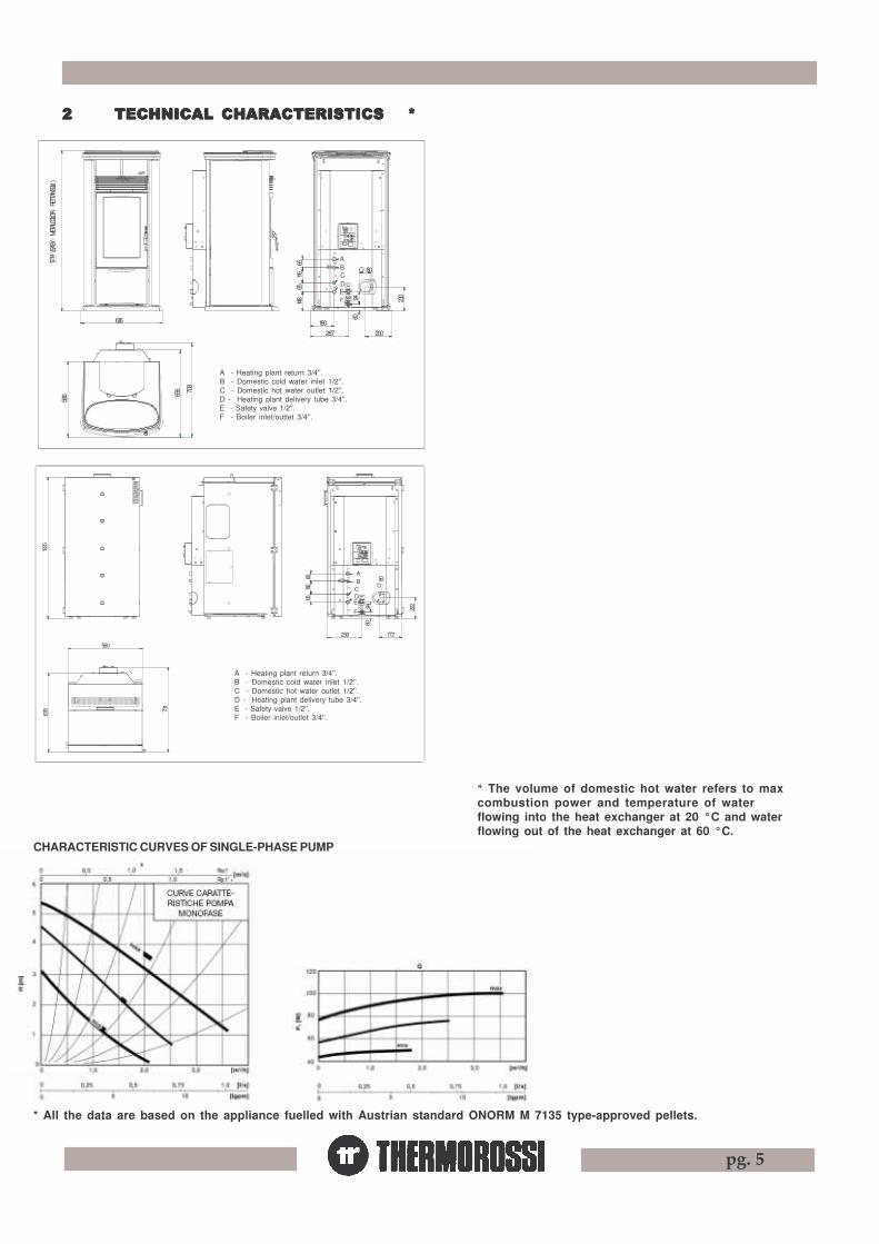
22222 TECHNICAL CHARACTERISTICS *TECHNICAL CHARACTERISTICS *TECHNICAL CHARACTERISTICS *TECHNICAL CHARACTERISTICS *TECHNICAL CHARACTERISTICS *
* All the data are based on the appliance fuelled with Austrian standard ÖNORM M 7135 type-approved pellets.
CHARACTERISTIC CURVES OF SINGLE-PHASE PUMP
* The volume of domestic hot water refers to maxcombustion power and temperature of waterflowing into the heat exchanger at 20 °C and waterflowing out of the heat exchanger at 60 °C.
148
65
566
616
656 70
8
(EASY
- ME
TALCO
LOR
- RET
TANG
OLI )
1214
F 230
287180
200
60
E116
65
O 80B
D
94
C
A
A - Heating plant return 3/4'’.B - Domestic cold water inlet 1/2'’.C - Domestic hot water outlet 1/2'’.D - Heating plant delivery tube 3/4'’.E - Safety valve 1/2'’.F - Boiler inlet/outlet 3/4'’.
678 73
1
560
1225
E
22294
60
259
F
172
6565
116 CD
BA
80O
A - Heating plant return 3/4'’.B - Domestic cold water inlet 1/2'’.C - Domestic hot water outlet 1/2'’.D - Heating plant delivery tube 3/4'’.E - Safety valve 1/2'’.F - Boiler inlet/outlet 3/4'’.

pg. 6
33333 GENERAL DESCRIPTIONGENERAL DESCRIPTIONGENERAL DESCRIPTIONGENERAL DESCRIPTIONGENERAL DESCRIPTION
3.13 .13 .13 .13 .1 OPERAOPERAOPERAOPERAOPERATING TING TING TING TING TECHNOLTECHNOLTECHNOLTECHNOLTECHNOLOGYOGYOGYOGYOGY•Your heater / boiler has been constructed to satisfy in full all your heating and practical needs. Top-grade components and functionsmanaged with microprocessor technology guarantee high reliability and optimal performance.
3.23 .23 .23 .23 .2 PELLETSPELLETSPELLETSPELLETSPELLETS•The appliance is fuelled by pellets, that is, cylinders of compressed sawdust; this will make it possible for you to enjoy to the full the heat of theflame without having to manually stoke the combustion.•The pellets are cylinders of compressed sawdust having a 6 mm diameter and a maximum length of 20 mm. They have a humidity content of max.8%, a thermal value 4000/4500 Kcal/Kg and a density of approx. 620-630 Kg/m³.
The use of fuel which does not comply with the description given above immediately voids the heater / boilerwarranty. Do not use the appliance as an incinerator, at the risk of voiding the warranty.
3.33 .33 .33 .33 .3 THE FEEDBOTHE FEEDBOTHE FEEDBOTHE FEEDBOTHE FEEDBOXXXXX
The feedbox is situated in the top part of the heater / boiler. The maximum loadcapacity of the tank is approximately 43 Kg, but varies according to the specificweight of the pellets.The manufacturer recommends emptying the hopper and vacuumingthe screw feeder zone once a month and during the summer period.Take special care when loading the hopper as the screw feeder at itsbase is in motion.
MF
N C D
GE
BA O
H
Q
P
IAD
3.43 .43 .43 .43 .4 MAIN COMPONENTS OF HEAMAIN COMPONENTS OF HEAMAIN COMPONENTS OF HEAMAIN COMPONENTS OF HEAMAIN COMPONENTS OF HEATER MODTER MODTER MODTER MODTER MOD..... H2O H2O H2O H2O H2O AND BOILER MODAND BOILER MODAND BOILER MODAND BOILER MODAND BOILER MOD..... COMP COMP COMP COMP COMPAAAAACTCTCTCTCT
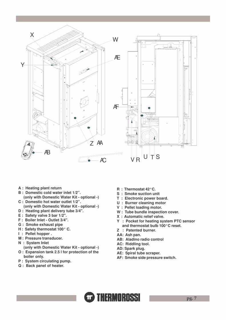
pg. 7
ZAB
AC V R
AA
U ST
X
Y
AF
AE
W
A : Heating plant returnB : Domestic cold water inlet 1/2'’. (only with Domestic Water Kit - optional -)C : Domestic hot water outlet 1/2'’. (only with Domestic Water Kit - optional -)D : Heating plant delivery tube 3/4".E : Safety valve 3 bar 1/2".F : Boiler Inlet - Outlet 3/4".G : Smoke exhaust pipeH : Safety thermostat 100° C.I : Pellet hopper .M : Pressure transducer.N : System Inlet (only with Domestic Water Kit - optional -)O : Expansion tank 2.5 l for protection of the
boiler only.P : System circulating pump.Q : Back panel of heater.
R : Thermostat 42°C.S : Smoke suction unitT : Electronic power board.U : Burner cleaning motorV : Pellet loading motor.W : Tube bundle inspection cover.X : Automatic relief valve.Y : Pocket for heating system PTC sensor
and thermostat bulb 100°C reset.Z : Patented burner.AA: Ash pan.AB: Aladino radio controlAC: Riddling tool.AD: Spark plug.AE: Spiral tube scraper.AF: Smoke side pressure switch.

pg. 8
The casing on the EASY model is factory-mounted before being packaged. To move the heater from the pallet the casing and the 2 screws that securethe heater to the wood pallet must firstly be removed.
44444 INSTINSTINSTINSTINSTALLAALLAALLAALLAALLATIONTIONTIONTIONTION
4.14 .14 .14 .14 .1 HEAHEAHEAHEAHEATER / BOILER LTER / BOILER LTER / BOILER LTER / BOILER LTER / BOILER LOCAOCAOCAOCAOCATIONTIONTIONTIONTION
CAUTION : Always use trolleys to move the appliance and the appliance must always be in a vertical position. The casing for the H2O is packedseparately. To unpack the Compact, once the wood crate has been removed, remove the casing (in reverse order as set out in par.4.2.3).Remove the screw at the base of the heater / boiler and remove the base from the bottom pallet. Follow the general guidelines set out inparagraph 1.1 to the letter. Above all ensure that the flooring of the room where the heater / boiler will be installed is capable of bearing the weightof the appliance plus the weight of the water contained in it and the weight of the pellets in the hopper.CAUTION: The room in which the appliance will operate must be adequately ventilated (minimum air intake 1300 m3/h).
The heater / boiler must be positioned at a minimum safe distancefrom walls and furnishings. This distance will have to beincreased considerably if the objects surrounding the applianceare inflammable (matchboarding, furniture, curtains, pictureframes, sofas, etc...). The recommended minimum distances areillustrated in the drawing below on the right.Installation in the vicinity of heat-sensitive materials is onlypermitted if suitable insulating protection is placed between theobject and the appliance (ref. Uni 10683).
4.2.14.2.14.2.14.2.14.2.1 MOUNTING METMOUNTING METMOUNTING METMOUNTING METMOUNTING METALALALALALCOLCOLCOLCOLCOLOR / EASYOR / EASYOR / EASYOR / EASYOR / EASYCASING FOR HEACASING FOR HEACASING FOR HEACASING FOR HEACASING FOR HEATER H2OTER H2OTER H2OTER H2OTER H2O
450 mm SE MATERIALE COMBUSTIBILE
450
mm SE
MAT
ERIAL
E COM
BUST
IBILE
450
mm SE
MAT
ERIAL
E COM
BUST
IBILE ISOLANTE TERMICO
450 mm SE MATERIALECOMBUSTIBILE
After positioning and levelling the heater by raising or lowering the mounting feet, connecting it to the heating system and to the electrical system(see par.4.4 , 4.5 , 4.6 , 4.7 , 4.8 , 4.9 , 4.10, 4.11 ), proceed to mount the casing as illustrated:
Carry out the procedure described below and follow the drawing on the next page:
- Remove the cover (A) .- Open the cover(D) , remove the screw (C) and remove the cover (E).- Fasten the 4 spacers (I) with the supplied nuts M4 (H) and screws M4x16 (L) to the lower base.- Adjust the heater mounting feet and position the kickplates (M) as illustrated, making sure that the kickplates are inserted under the plate (PT); then check that the door can be easily removed (PC) and if necessary raise the feet.- Mount the side panels by firstly inserting the lower holes on the spacers (I) that were fastened beforehand.- Fasten the screws (F) to lock the side panels (G).- Mount the cast iron cover (E) , the cover (A) and fasten the screw (C) .
4.24 .24 .24 .24 .2 MOUNTING HEAMOUNTING HEAMOUNTING HEAMOUNTING HEAMOUNTING HEATERTERTERTERTER / BOILER/ BOILER/ BOILER/ BOILER/ BOILER CASINGCASINGCASINGCASINGCASING.....
KEY450 mm if thematerial iscombustible
Heat insulatingmaterial
LEGENDA
450 mm sematerialecombustibile
Isolante termico

pg. 9
PC
M
L
HI
A
PT
M
GF
C
D
E
F
4.2.24.2.24.2.24.2.24.2.2 MOUNTING RECTMOUNTING RECTMOUNTING RECTMOUNTING RECTMOUNTING RECTANGULAR CERAMIC ANGULAR CERAMIC ANGULAR CERAMIC ANGULAR CERAMIC ANGULAR CERAMIC TILE CASING FOR HEATILE CASING FOR HEATILE CASING FOR HEATILE CASING FOR HEATILE CASING FOR HEATER H2OTER H2OTER H2OTER H2OTER H2O.....
After positioning and levelling the heater by raising or lowering the mounting feet, connecting it to the heating system and to the electricalsystem (see par.4.4 , 4.5 , 4.6 , 4.7 , 4.8 , 4.9 , 4.10, 4.11 ), proceed to mount the casing as illustrated:-Open the cover (D) and undo and remove the screw (C), then remove the cover (E) (figure 1).Unpack the ceramic casing then proceed to secure the flat ceramic tiles with rectangular decor (CP) and the convex ceramic tiles (CT) tothe steel backing plates (SA) :-Fasten the steel backing plates to each other using the screws M4x12 (O), the washers d.4 (P), the nuts M4 (Q) (see figure 2). Place theelements on a flat surface ( e.g. a table) to secure them and make sure that the edges match up (see detail figure 2 )-Next fasten the flat tiles to the steel backing plate using the screws M3 x 6 (R) and washers d.3 (S) provided (see figure 3): to carry outthis operation place the flat tiles on a table and lay the steel backing plate (SA) on top, then fasten them with screws and washers. Handlethe ceramic tiles with extreme care to prevent accidental breakages.-Then secure the convex ceramics to the steel backing plate with the screws M3 x 6 (R) and washers d.3 (S) (see figure 3): to carry outthis operation fasten the ceramics to the steel support (SA) with screws and washers as illustrated in figure 4 and adjust their alignmentwith the flat ceramics. Handle the ceramic tiles with extreme care to prevent accidental breakages.-Do not tighten the screws M3X6 (R) excessively as this could damage the ceramic tiles; this damage is not covered by warranty.
4.2.14.2.14.2.14.2.14.2.1 MOUNTING METMOUNTING METMOUNTING METMOUNTING METMOUNTING METALALALALALCOLCOLCOLCOLCOLOR / EASYOR / EASYOR / EASYOR / EASYOR / EASYCASING FOR HEACASING FOR HEACASING FOR HEACASING FOR HEACASING FOR HEATER H2OTER H2OTER H2OTER H2OTER H2O

pg. 10
-Adjust the heater mounting feet.-Position the kickplates (M) (figure 5 and figure 6 ), then check that the door (PC) can be removed and if necessary raise the mounting feet, mountthe side with ceramic tiles by firstly inserting the bottom folds on the base and fastening with the 2 screws (F) at the top.-Next mount the cover (E) and secure it with the screw (C) (figure 1) .-Lastly position the ceramic top.
It is important to take special care when mounting the ceramic side panels (CP) and the sheet metal support (SA) in order to preventirregular bending which could cause breakages not covered by warranty.
Small imperfections on the surfaces of the ceramics such as: dimples, shivering and slight colour variations are normal characteristicsof handcrafted ceramics which make each piece unique. Remove any stickers from the brass bushes to facilitate screwing in thescrews M3.
E
CT
R
SA
S
CP
D
C
ALLINEARE
SA
Dettaglio
SA
Q
P
O
KEYFigure 1-2-3-4AlignDetail
LEGENDAFigura 1-2-3-4Allinearedettaglio

pg. 11
Figura 5
FF
M
M
Figura 6
PC
CP
F C P
- Firstly remove the protective film from the casing.- Next mount the 2 side panels (F) by inserting the 2 holes of thebottom fold on the pins of the base and fastening the 2 topscrews with a screwdriver.- Fasten the front cover (C) by fitting it onto the side panels.- Fasten the door (P) to the left side with the special hinges andscrews provided.- Lastly fit the back cover (CP) on the front cover (C) andfasten the hinges with the screws provided.
If you prefer the door (P) can be mounted with the handle on theleft and the hinges on the right. Simply remove the handle (M)from the door and fix it to the holes on the left side of the door,remove the 3 hinges (T) and fix them to the right side of the door.Similarly, remove the magnet from the right side of the door andmount it on the left side of the door.
To increase the boiler’s autonomy of operation it is possible to install one or two additional hoppers at the sides of the boiler. Each additionalhopper can hold up to 100 Kg of pellets.Firstly unpack the hopper then assemble it as follows:- Fasten the 4 telescopic legs (A) using the screws provided (screws TSP+ 8x50).- Fasten the pellet chute (attention: use chute B1) to the hopper using the screws provided (screws TC+4.8x13).- Mount the panel (C) by inserting the bottom folds on the holes of the hopper, and then securing it using the screws provided (screws
TC+4.8x13).- Similarly fasten the panel (E) using the screws provided (screws TC+4.8x13).- Then mount the panel (D) by lining up the lower rectangular holes on the panel folds (E) and fastening them using the screws provided
(screws TC+4.8x13).- The panels (D) and (E) can be mounted either to the right or to the left of the pellet chute (B1); if mounted on the right the additional hopperwill have to be mounted to the right of the boiler. .- Fix the panel (G) by firstly inserting the holes on the bottom on the mounting feet then securing them with the screws provided (screwsTC+4.8x13).- Next mount the panel (F) by inserting the bottom folds on the holes in the panel (G).
After positioning and levelling the boiler by raising or lowering the mounting feet, connecting it to the heating system and to the electrical system(see par.4.4 , 4.5 , 4.6 , 4.7 , 4.8 , 4.9 , 4.10, 4.11 ), proceed to mount the casing as illustrated below:
4.2.34.2.34.2.34.2.34.2.3 HO HO HO HO HOW W W W W TTTTTO MOUNT O MOUNT O MOUNT O MOUNT O MOUNT THE COMPTHE COMPTHE COMPTHE COMPTHE COMPAAAAACT BOILER CASINGCT BOILER CASINGCT BOILER CASINGCT BOILER CASINGCT BOILER CASING
4.2.44.2.44.2.44.2.44.2.4 HO HO HO HO HOW W W W W TTTTTO INSTO INSTO INSTO INSTO INSTALL ALL ALL ALL ALL ADDITIONADDITIONADDITIONADDITIONADDITIONAL HOPPER (OPTIONAL HOPPER (OPTIONAL HOPPER (OPTIONAL HOPPER (OPTIONAL HOPPER (OPTIONAL) AL) AL) AL) AL) WITH COMPWITH COMPWITH COMPWITH COMPWITH COMPAAAAACT BOILER.CT BOILER.CT BOILER.CT BOILER.CT BOILER.

pg. 12
VITE TC+ 4,8X13 (2 pz.)
VIT
E T
C+
4,8X
13 (
2 pz
.)
F
G
H
E
VITE TC+ 4,8X13 (2 pz.)
D
VITE TC+ 4,8X13 (4 pz.)
A
B
VITE TC+ 4,8X13 (4 pz.)
VITE TC+ 4,8X13 (2 pz.)
VITE TSP+ 8X50 + DADO (4 pz.)
C
B1
VITE TC+ 4,8X13 (2 pz.)
H F
I
After having mounted the additionalhopper fasten the hopper to the boiler:- Remove the octagonal portion of
precut sheet metal from the side (F)of the boiler
- Remove the cap (I) from the hopperby undoing the screws fastened to it.
- Move the additional tank up againstthe boiler by adjusting the mountingfeet (H) until the assembly issatisfactory.
- Fasten the assembly using thescrews previously removed from thecap (I).
4.2.54.2.54.2.54.2.54.2.5 HO HO HO HO HOW W W W W TTTTTO FO FO FO FO FASTEN ASTEN ASTEN ASTEN ASTEN THE THE THE THE THE ADDITIONADDITIONADDITIONADDITIONADDITIONAL HOPPER (OPTIONAL HOPPER (OPTIONAL HOPPER (OPTIONAL HOPPER (OPTIONAL HOPPER (OPTIONAL) AL) AL) AL) AL) TTTTTO COMPO COMPO COMPO COMPO COMPAAAAACT BOILER.CT BOILER.CT BOILER.CT BOILER.CT BOILER.
KEYSCREW TC
SCREW TSP
2/4 pcs.
NUT
LEGENDA
VITE TC
VITE TSP
2/4 pz.
DADO

pg. 13
1
M P
EF
C
DO N
BA
X
H
4.34 .34 .34 .34 .3 HYDRA HYDRA HYDRA HYDRA HYDRAULIC DRAULIC DRAULIC DRAULIC DRAULIC DRAWING FOR HEAWING FOR HEAWING FOR HEAWING FOR HEAWING FOR HEATER HTER HTER HTER HTER H22222O / COMPO / COMPO / COMPO / COMPO / COMPAAAAACT .CT .CT .CT .CT .
CAUTION: FOR THE DELIVERY, RETURN, MAKE-UP AND DISCHARGE CONNECTIONS USE FLEXIBLE TUBES HAVING ALENGTH OF AT LEAST 70 CM TO FACILITATE MOVING THE APPLIANCE FOR MAINTENANCE.CAUTION: A CONNECTION MUST BE MADE BETWEEN THE SAFETY VALVE AND THE OUTLET TO PREVENT DAMAGINGMATERIALS SURROUNDING THE BOILER/HEATER WHEN THE VALVE IS ACTIVATED.(SEE PAR. 4.4 - 4.5 - 4.6 - 4.7 - 4.8 - 4.9 ).
A : Heating plant returnC : Domestic hot water outlet 1/2'’. (only
with Domestic Water Kit - optional -)E : Safety valve 3 bar 1/2".H : Safety thermostat 100° C.M : Pressure transducer.O : Expansion tank 2.5 l for protection of the
boiler only .X : Automatic relief valve.
B : Domestic cold water inlet 1/2'’. (onlywith Domestic Water Kit - optional -)
D : Heating plant delivery tube 3/4".F : Boiler Inlet - Outlet 3/4". (only with
Domestic Water Kit - optional -)N : System InletP : System circulating pump.1 : Boiler sensor

pg. 14
A : andata impianto riscaldamentoR : ritorno impianto riscaldamentoS : saracinescaVNR : valvola di non ritornoVEC : vaso di espansione chiuso per protezione impiantoVR : valvola riduttrice di pressioneVM : valvola miscelatrice
4.4 EXAMPLE OF HYDRA4.4 EXAMPLE OF HYDRA4.4 EXAMPLE OF HYDRA4.4 EXAMPLE OF HYDRA4.4 EXAMPLE OF HYDRAULIC DRAULIC DRAULIC DRAULIC DRAULIC DRAWING FOR HWING FOR HWING FOR HWING FOR HWING FOR H22222O / COMPO / COMPO / COMPO / COMPO / COMPAAAAACT ONLCT ONLCT ONLCT ONLCT ONLY HEAY HEAY HEAY HEAY HEATING .TING .TING .TING .TING .
A : andata impianto riscaldamentoR : ritorno impianto riscaldamentoS : saracinescaVNR : valvola di non ritornoVEC : vaso di espansione chiuso per protezione impiantoVR : valvola riduttrice di pressioneVM : valvola miscelatrice
4.5 EXAMPLE OF HYDRA4.5 EXAMPLE OF HYDRA4.5 EXAMPLE OF HYDRA4.5 EXAMPLE OF HYDRA4.5 EXAMPLE OF HYDRAULIC DRAULIC DRAULIC DRAULIC DRAULIC DRAWING FOR HWING FOR HWING FOR HWING FOR HWING FOR H222220 / COMP0 / COMP0 / COMP0 / COMP0 / COMPAAAAACT CT CT CT CT WITH WITH WITH WITH WITH AIR/CASED BOILER AIR/CASED BOILER AIR/CASED BOILER AIR/CASED BOILER AIR/CASED BOILER TUBESTUBESTUBESTUBESTUBES
CAUTION : The water temperature in the boiler tubes in this case is not adjustable and depends on the systems’s delivery temperature, thatis the max temperature t setting.
DAR
SCA
A: heating plant deliveryR: heating plant returnS: gate valveVNR: nonreturn valveVEC: closed expansion tank for plant
protectionVR: reducing valveVM: mixing valveDAR: from water mains for make-upSCA: discharge
BOI
DAR
SCA
A: heating plant deliveryR: heating plant returnS: gate valveVNR: nonreturn valveVEC: closed expansion tank for plant
protectionVR: reducing valveVM: mixing valveDAR: from water mains for make-upSCA: dischargeBOI: Air-cased boiler

pg. 15
A : andata impianto riscaldamentoR : ritorno impianto riscaldamentoS : saracinescaVNR : valvola di non ritornoVEC : vaso di espansione chiuso per protezione impiantoVM3V : valvola motorizzata 3 vie TB : termostato bollitoreVR : valvola riduttrice di pressioneVM : valvola miscelatrice
4.64 .64 .64 .64 .6 EXAMPLE OF HYDRA EXAMPLE OF HYDRA EXAMPLE OF HYDRA EXAMPLE OF HYDRA EXAMPLE OF HYDRAULIC DRAULIC DRAULIC DRAULIC DRAULIC DRAWING FOR HWING FOR HWING FOR HWING FOR HWING FOR H222220 HEA0 HEA0 HEA0 HEA0 HEATER / COMPTER / COMPTER / COMPTER / COMPTER / COMPAAAAACT CT CT CT CT WITH BOILER COILSWITH BOILER COILSWITH BOILER COILSWITH BOILER COILSWITH BOILER COILS
In order to guarantee correct absorption of the heat produced by the generator is it is advisable to use a boiler tube withvolume and heat exchange capacity suitable for the power of the generator.
DARSCA
A: heating plant deliveryR: heating plant returnS: gate valveVNR: nonreturn valveVEC: closed expansion tank for plant protectionVM3V: 3-way motor-operated valveTB: boiler tubes thermostatVR: reducing valveVM: mixing valveDAR: from water mains for make-upSCA: discharge
4.74 .74 .74 .74 .7 EXAMPLE OF HYDRAEXAMPLE OF HYDRAEXAMPLE OF HYDRAEXAMPLE OF HYDRAEXAMPLE OF HYDRAULIC DRAULIC DRAULIC DRAULIC DRAULIC DRAWING FOR H20 /COMPWING FOR H20 /COMPWING FOR H20 /COMPWING FOR H20 /COMPWING FOR H20 /COMPAAAAACT CT CT CT CT WITH �KIT FOR WITH �KIT FOR WITH �KIT FOR WITH �KIT FOR WITH �KIT FOR THE PRTHE PRTHE PRTHE PRTHE PRODUCTIONODUCTIONODUCTIONODUCTIONODUCTIONOF INSTOF INSTOF INSTOF INSTOF INSTANT DOMESTIC HOANT DOMESTIC HOANT DOMESTIC HOANT DOMESTIC HOANT DOMESTIC HOT T T T T WWWWWAAAAATER TER TER TER TER � (OPTIONAL).
Rubinetto di carico impianto riscaldamento
A : andata impianto riscaldamento VNR : valvola di non ritornoR : ritorno impianto riscaldamento VEC : vaso di espansione S : saracinesca chiuso per protezione impiantoVR : valvola riduttrice di pressione VM : valvola miscelatrice.
CB
The diverting valve switches the water to the plate heat exchanger of the “Domestic hot water production kit “ when the flow switch detectsthe passage of water towards the usage point and when the boiler temperature exceeds 61° C. When there is a request for hot water theboiler operates at maximum steady state power level. See also paragraph 5.1.8.
SCA
VNR: nonreturn valveVEC: closed expansion tank for plant
protectionVM: mixing valveSCA: discharge
SR
AD
DOS
UT
DOS: polyphosphates meteringdevice
SR: salts for resinsAD: water softenerUT: to the usage pointDA: from water mainsF: filter
A: heating plant deliveryR: heating plant returnS: gate valveVR: reducing valve
DAF
heating system inlet tap

pg. 16
A : andata impianto riscaldamento VM3V : valvola motorizzata 3 vie R : ritorno impianto riscaldamento S : saracinescaVNR : valvola di non ritorno VEC : vaso di espansione chiuso per protezione impiantoTB : termostato bollitore VR : valvola riduttrice di pressione VM : valvola miscelatrice
A : andata impianto riscaldamento VNR : valvola di non ritorno R : ritorno impianto riscaldamento VEC : vaso espansione chiuso protezione impianto S : saracinesca VECP : vaso espansione chiuso protezione pannelli solari VR : valvola riduttrice di pressione PR : pannelli radianti PS : pannello solari VM : valvola miscelatrice A : accumulo
Reint
egro
BC
Rubinetto di carico impianto riscaldamento
impia
nto
4.94 .94 .94 .94 .9 EXAMPLE OF HYDRAEXAMPLE OF HYDRAEXAMPLE OF HYDRAEXAMPLE OF HYDRAEXAMPLE OF HYDRAULIC DRAULIC DRAULIC DRAULIC DRAULIC DRAWING FOR H20 /COMPWING FOR H20 /COMPWING FOR H20 /COMPWING FOR H20 /COMPWING FOR H20 /COMPAAAAACT CT CT CT CT WITH PUFFER SYWITH PUFFER SYWITH PUFFER SYWITH PUFFER SYWITH PUFFER SYSTEM STEM STEM STEM STEM WITHWITHWITHWITHWITHSOLAR PSOLAR PSOLAR PSOLAR PSOLAR PANELS ANELS ANELS ANELS ANELS AND HEAAND HEAAND HEAAND HEAAND HEATING TING TING TING TING WITH RADIAWITH RADIAWITH RADIAWITH RADIAWITH RADIATING PTING PTING PTING PTING PANELSANELSANELSANELSANELS.....
A : andata impianto riscaldamento VM3V : valvola motorizzata 3 vie R : ritorno impianto riscaldamento S : saracinescaVNR : valvola di non ritorno VEC : vaso di espansione chiuso per protezione impiantoTB : termostato bollitore VR : valvola riduttrice di pressione VM : valvola miscelatrice
4.84 .84 .84 .84 .8 EXAMPLE OF HYDRAEXAMPLE OF HYDRAEXAMPLE OF HYDRAEXAMPLE OF HYDRAEXAMPLE OF HYDRAULIC DRAULIC DRAULIC DRAULIC DRAULIC DRAWING FOR H20 /COMPWING FOR H20 /COMPWING FOR H20 /COMPWING FOR H20 /COMPWING FOR H20 /COMPAAAAACT CT CT CT CT WITH HEADER SYWITH HEADER SYWITH HEADER SYWITH HEADER SYWITH HEADER SYSTEM STEM STEM STEM STEM ANDANDANDANDANDZONE ZONE ZONE ZONE ZONE VVVVVALALALALALVESVESVESVESVES.....
CHRONOTHERMOSTAT MODEM CONTACTT.A.
Sol
enoi
d va
lve
alw
ays
open
(zon
e w
ith th
e m
ost a
bsor
ptio
n)
HEADER
HEADER
ROOM TEMPERATURETHERMOSTAT OF THE ZONEWITH THE MOST ABSORPTION
discharge
discharge
from water mainsFor make-up
Remarks: Heat must be dissipated; the solenoid valve must be open for the following reasons:-to prevent the generator from continually switching on and off due to inevitable slight heat loss at the header-to prevent the generator from raising the water temperature by a few degrees each time it is switched off then back on until it shuts downdue to exceeding the maximum threshold temperature of 98°C (manually reset thermostat).We recommend, in order to adjust the room temperature to the temperature at which the valve opened, connecting the room temperaturethermostat to the CHRONOTHERMOSTAT - MODEM terminal (clean contact COM-NO see par. 6) that permits the machine to be shut off by anexternal contact and consequently also started up again by an external contact. Using this system the generator will only be activated ifthere is a real request for heat from the zone and the continual switching off due to temporary lowering of temperature due to the tubing andpossibly the header will be avoided. More than one parallel room temperature thermostats can be connected to the chronothermostat modemterminal. In this way the zone that closes the contact (request for heat ) before the others automatically makes the generator start up.
A: heating plant deliveryR: heating plant returnVNR: nonreturn valveTE: boiler tubes thermostatVM: mixing valve
VM3V: 3-way motor-operated valveS: gate valveVEC: closed expansion tank for plant protectionVR: reducing valve
polyphosphatesmetering device
filter
polyphosphatesmetering device
saltsforresins w
ater
sof
tene
r
discharge
to the usagepoint
from watermains
Heating system inlet tap
SY
ST
EM
MA
KE
-UP
discharge
A: heating plant deliveryVEC: closed expansion tank for plant protectionVR: reducing valveVM: mixing valve
VNR: nonreturn valveS: gate valvePR: radiating panelsA: puffer
R: heating plant returnVECP: closed expansion tank for protection of
solar panelsPS: solar panels

pg. 17
The safety valve must be connected to the highest part of the heat generator or the outlet tube, next to the generator. The length of the sectionof tube between the generator fitting and the safety valve must not be more than one metre. There must be no cocks that can cut off the tubeconnecting the safety valve to the heat generator and the section must not be less than the inlet section of the safety valve or the sum of the inletsections if there are several valves that head a single tube, at any point whatsoever along its length. The outlet tube of the safety valve must beinstalled in such a way that it does not prevent the normal functioning of the valves and will not cause injury to persons ; the outlet must be locatedas close as possible to the safety valve and be accessible and visible. The diameter of the outlet tube must not in any case be less than thediameter of the safety valve outlet fitting. The outlet fitting diameter is the minimum internal diameter of the valve outlet upstream from any existinginternal threading. The valve discharge pressure, equal to the calibration pressure and increased by the overpressure, must not exceed themaximum working pressure of the heat generator. The designer must ensure that the maximum pressure existing at every point of the systemdoes not exceed the maximum working pressure of each of its components. The discharge capacity of the safety valve must be calculatedaccording to the prescriptions set out in UNI 10412/2. The diameter of the minimum net cross section of the valve inlet must in any case be notless than 15 mm. The maximum working pressure of the closed expansion tank must not be less than the calibration pressure of thesafety valve, plus the specific overpressure of the valve itself, with any difference in height between the tank and the valve taken intoaccount,and the pressure generated by the functioning of the pump. The capacity of the expansion tank or tanks is evaluated according to theoverall capacity of the plant as per the design. The closed expansion tanks must comply with current regulations governing pressure appliances
in terms of design, construction, conformity assessment and utilization.The rated volume of the closed expansion tank must be sized in relation to the expansion volume of the water in thesystem. The heat generator must be connected directly to the plant’s expansion tank or group of expansion tanks with a tube havingan internal diameter no less than 18 mm. The connecting tube, which may consist of plant parts, must not be fitted with any shutoff
cocks or have reduced sections. One three-way on-off valve may be installed for connecting the tank to the atmosphere for maintenanceoperations. This device must be protected against accidental manouevres. The connecting tube must be fitted in such a way that no scaling ordeposit points are created. If several heat generators power a single system or secondary circuit, each heat generator must be connecteddirectly to the system’s expansion tank or group of expansion tanks sized overall for the total volume of water contained in the same plant orindependent circuit. When it is necessary to separate the single heat generator from the expansion tank or group of expansion tanks, then athree-way tap having the same characteristics as those listed above must be installed on the tube that connects the generator to the expansiontank, in order to ensure that the generator is in any case connected either with the expansion tank or with the atmosphere in every position.The expansion tanks, connecting tubes, the vent and smoke exhaust pipes must be protected against freezing in areas where this could occur.The solution adopted for this purpose must be described in the project. Given that the circulation of the water in the heat generator must bemaintained in any system and in all operating conditions within the limits prescribed by the supplier of the generator, in closed expansion tankheating systems, in which the circulation of the water is assured by means of an electric pump, the pump stopping must not cause, in anyoperating condition, the temperature to rise above the limit prescribed in these instructions.
The previous chapter does not replace UNI 10412/2 to which it makes reference . The qualified installer must in any casebe fully aware of this standard and its amending versions.
4.10 INSTR4.10 INSTR4.10 INSTR4.10 INSTR4.10 INSTRUCTIONS FOR EXECUTING HYDRAUCTIONS FOR EXECUTING HYDRAUCTIONS FOR EXECUTING HYDRAUCTIONS FOR EXECUTING HYDRAUCTIONS FOR EXECUTING HYDRAULIC SYULIC SYULIC SYULIC SYULIC SYSTEM.STEM.STEM.STEM.STEM.
Instructions for closed system
Systems with closed expansion tank, must be provided with :a) safety valve b) thermal relief valve or thermal safety outlet (positive safety )c) closed expansion tank d) circulating pump activation thermostat (included in the panel of the central heating cooker).e) acoustic alarm activation thermostat f) acoustic alarmg) pressure gauge thermometer h) circulation system
These devices must be installed on the generator’s delivery tube, within not more than 1 metre from the machine.
pg. 18
RETRO INFERIORE
RISCALDAMENTO ( TIPO 1 )
SUPPORTO GRUPPOFERMATUBOCOLLARE
VITE
VITE
GUARNIZIONE
VITE
COMPLETO PREMONTATO
DI SCARICORUBINETTO
TUBO MANDATA
RISCALDAMENTO ( TIPO 2 )
PREMONTATOGRUPPO COMPLETO
TUBO MANDATA
VITI DI MONTAGGIOGRUPPO COMPLETOPREMONTATO.
GHIERA
GUARNIZIONE
VITE
VITE
VITE
VITE
VITE
VITE
GASKET
FLUSSOSTATO
TUBO MANDATA RISCALDAMENTO
COLLARE FERMATUBOCOMPLETO DI VITE
VALV
OLA D
EVIAT
RICE
CAVO VALVOLA DEVIATRICE
GUARNIZIONE
CORPO RITORNOSCAMBIATORE A PIASTRE
GUARNIZIONE
CORPO MANDATA
IMPIA
NTO
RISCA
LDAM
ENTO
RUBIN
ETTO
CARIC
O
VITE
VITE
CAVO FLUSSOSTATO
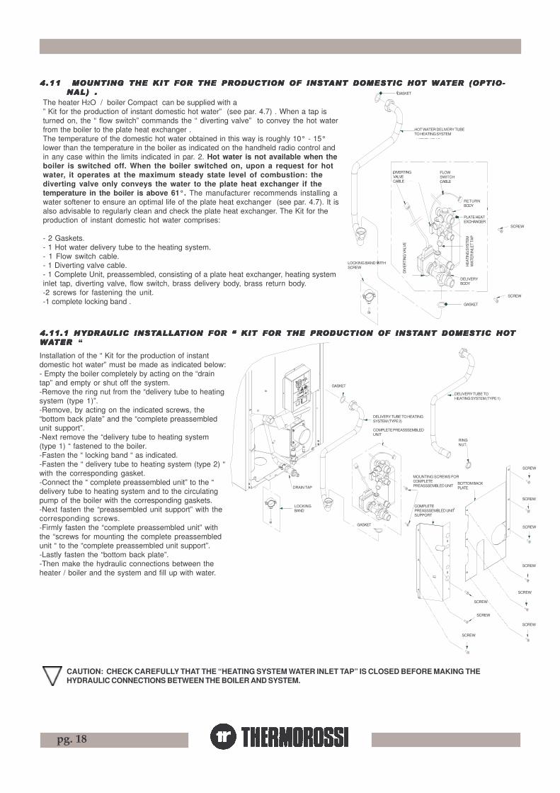
The heater H2O / boiler Compact can be supplied with a” Kit for the production of instant domestic hot water” (see par. 4.7) . When a tap isturned on, the “ flow switch” commands the “ diverting valve” to convey the hot waterfrom the boiler to the plate heat exchanger .The temperature of the domestic hot water obtained in this way is roughly 10° - 15°lower than the temperature in the boiler as indicated on the handheld radio control andin any case within the limits indicated in par. 2. Hot water is not available when theboiler is switched off. When the boiler switched on, upon a request for hotwater, it operates at the maximum steady state level of combustion: thediverting valve only conveys the water to the plate heat exchanger if thetemperature in the boiler is above 61°. The manufacturer recommends installing awater softener to ensure an optimal life of the plate heat exchanger (see par. 4.7). It isalso advisable to regularly clean and check the plate heat exchanger. The Kit for theproduction of instant domestic hot water comprises:
- 2 Gaskets.- 1 Hot water delivery tube to the heating system.- 1 Flow switch cable.- 1 Diverting valve cable.- 1 Complete Unit, preassembled, consisting of a plate heat exchanger, heating systeminlet tap, diverting valve, flow switch, brass delivery body, brass return body.-2 screws for fastening the unit.-1 complete locking band .
4.114.114.114.114.11 MOUNTING MOUNTING MOUNTING MOUNTING MOUNTING THE KIT FOR THE KIT FOR THE KIT FOR THE KIT FOR THE KIT FOR THE PRTHE PRTHE PRTHE PRTHE PRODUCTION OF INSTODUCTION OF INSTODUCTION OF INSTODUCTION OF INSTODUCTION OF INSTANT DOMESTIC HOANT DOMESTIC HOANT DOMESTIC HOANT DOMESTIC HOANT DOMESTIC HOT T T T T WWWWWAAAAATER (OPTIO-TER (OPTIO-TER (OPTIO-TER (OPTIO-TER (OPTIO-NAL) .NAL) .NAL) .NAL) .NAL) .
Installation of the “ Kit for the production of instantdomestic hot water” must be made as indicated below:- Empty the boiler completely by acting on the “draintap” and empty or shut off the system.-Remove the ring nut from the “delivery tube to heatingsystem (type 1)”.-Remove, by acting on the indicated screws, the“bottom back plate” and the “complete preassembledunit support”.-Next remove the “delivery tube to heating system(type 1) “ fastened to the boiler.-Fasten the “ locking band “ as indicated.-Fasten the “ delivery tube to heating system (type 2) “with the corresponding gasket.-Connect the “ complete preassembled unit” to the “delivery tube to heating system and to the circulatingpump of the boiler with the corresponding gaskets.-Next fasten the “preassembled unit support” with thecorresponding screws.-Firmly fasten the “complete preassembled unit” withthe “screws for mounting the complete preassembledunit “ to the “complete preassembled unit support”.-Lastly fasten the “bottom back plate”.-Then make the hydraulic connections between theheater / boiler and the system and fill up with water.
4.11.1 HYDRA4.11.1 HYDRA4.11.1 HYDRA4.11.1 HYDRA4.11.1 HYDRAULIC INSTULIC INSTULIC INSTULIC INSTULIC INSTALLAALLAALLAALLAALLATION FOR � KIT FOR TION FOR � KIT FOR TION FOR � KIT FOR TION FOR � KIT FOR TION FOR � KIT FOR THE PRTHE PRTHE PRTHE PRTHE PRODUCTION OF INSTODUCTION OF INSTODUCTION OF INSTODUCTION OF INSTODUCTION OF INSTANT DOMESTIC HOANT DOMESTIC HOANT DOMESTIC HOANT DOMESTIC HOANT DOMESTIC HOTTTTTWWWWWAAAAATER TER TER TER TER �
CAUTION: CHECK CAREFULLY THAT THE “HEATING SYSTEM WATER INLET TAP” IS CLOSED BEFORE MAKING THEHYDRAULIC CONNECTIONS BETWEEN THE BOILER AND SYSTEM.
GASKET
HOT WATER DELIVERY TUBETO HEATING SYSTEM
DIVERTINGVALVECABLE
FLOWSWITCHCABLE
RETURNBODY
PLATE HEATEXCHANGER
HEA
TIN
G S
YSTE
MW
ATE
R IN
LET
TAP
SCREW
DELIVERYBODY
SCREW
GASKET
LOCKING BAND WITHSCREW
DIV
ER
TIN
G V
ALV
E
SCREW
RINGNUT
SCREW
SCREW
SCREW
SCREW
SCREW
SCREW
SCREW
SCREW
GASKET
DRAIN TAP
LOCKINGBAND
DELIVERY TUBE TO HEATINGSYSTEM (TYPE 2)
COMPLETE PREASSSEMBLEDUNIT
BOTTOM BACKPLATE
MOUNTING SCREWS FORCOMPLETEPREASSSEMBLED UNIT
COMPLETEPREASSSEMBLED UNITSUPPORT
DELIVERY TUBE TOHEATING SYSTEM (TYPE 1)
pg. 19
5.15.15.15.15.1 HANDHELD RADIO CONTROLHANDHELD RADIO CONTROLHANDHELD RADIO CONTROLHANDHELD RADIO CONTROLHANDHELD RADIO CONTROL
5.1.15.1.15.1.15.1.15.1.1 DESCRIPTION OF DESCRIPTION OF DESCRIPTION OF DESCRIPTION OF DESCRIPTION OF THE HANDHELD RADIO CONTRTHE HANDHELD RADIO CONTRTHE HANDHELD RADIO CONTRTHE HANDHELD RADIO CONTRTHE HANDHELD RADIO CONTROL OL OL OL OL AND AND AND AND AND THE BTHE BTHE BTHE BTHE BAAAAACK PCK PCK PCK PCK PANEL FOR HEAANEL FOR HEAANEL FOR HEAANEL FOR HEAANEL FOR HEATER H2O /TER H2O /TER H2O /TER H2O /TER H2O /BOILER COMPBOILER COMPBOILER COMPBOILER COMPBOILER COMPAAAAACTCTCTCTCT
INTRODUCTIONThe handheld radio control is the control instrument for your heater / boiler that will permit you to manage Ecotherm and its functions. Theradio control is a user-friendly way of interacting with the main heater settings and, when required, of accessing the various other controlcommands. In both cases the Manufacturer recommends you read the following pages carefully so that you will know how to make the bestuse of your appliance. Keep in mind that radio wave transmissions can be affected by the surrounding environment: the presence of thickwalls can reduce the transmission that normally extends to 6-7 metres.
The first time you start the insert the radio control must be connected to the power supply by means of thebattery charger provided ( charge for at least 12 hours: see para. 7.4), as the rechargeable batteries could bepartially or completely flat). The heater / boiler must be energised and the switch turned to position “1”.
5.1.1.1 HANDHELD RADIO CONTROL5.1.1.1 HANDHELD RADIO CONTROL5.1.1.1 HANDHELD RADIO CONTROL5.1.1.1 HANDHELD RADIO CONTROL5.1.1.1 HANDHELD RADIO CONTROL
A description of the buttons and indicators on the radio control follows:The handheld radio control consists of a plastic shell on which is installed a backlit LCD display with control buttons, interface card andrechargeable batteries: the backlighting switches off temporarily during use in order to reduce energy consumption which consequentlyextends the duration of the charge.The two main control buttons are identified by the fan symbol °C (2) and by the flame symbol (1). The flame button (1) sets the appliancepower, and the 5 available power levels are indicated by the progressive lighting of the 5 bars in sequence (7)It is possible to select AUTOMATIC operating mode by means of the word AUTO (see paragraph 5.1.11.4 ).The shutdown cycle appears on the display when all the power bars are off.The button (2), commands the setting for the temperature of the water in the boiler. The setting range is between 65 °C and 73 °C.
FLUSSOSTATOCONNESSIONE
VALV
OLA D
EVIAT
RICE
CONN
ESSIO
NE
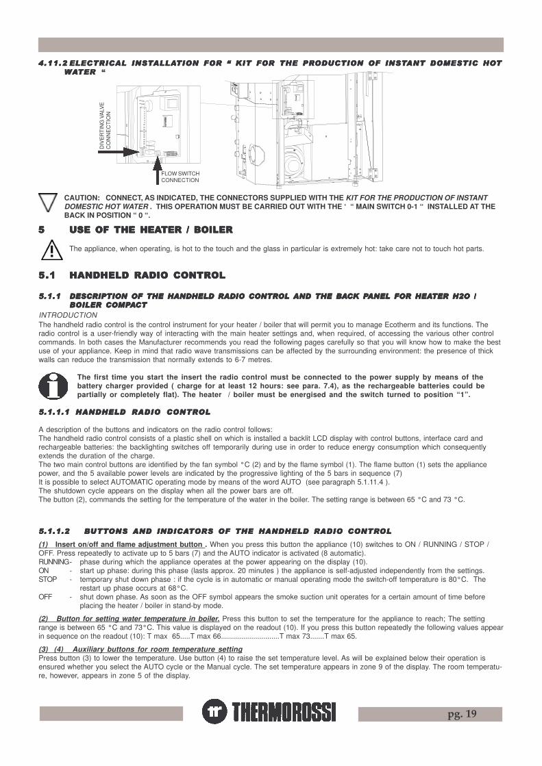
CAUTION: CONNECT, AS INDICATED, THE CONNECTORS SUPPLIED WITH THE KIT FOR THE PRODUCTION OF INSTANTDOMESTIC HOT WATER . THIS OPERATION MUST BE CARRIED OUT WITH THE ‘ “ MAIN SWITCH 0-1 “ INSTALLED AT THEBACK IN POSITION “ 0 “.
5.1.1.2 B5.1.1.2 B5.1.1.2 B5.1.1.2 B5.1.1.2 BUTTUTTUTTUTTUTTONS ONS ONS ONS ONS AND INDICAAND INDICAAND INDICAAND INDICAAND INDICATTTTTORS OF ORS OF ORS OF ORS OF ORS OF THE HANDHELD RADIO CONTRTHE HANDHELD RADIO CONTRTHE HANDHELD RADIO CONTRTHE HANDHELD RADIO CONTRTHE HANDHELD RADIO CONTROLOLOLOLOL
(1) Insert on/off and flame adjustment button . When you press this button the appliance (10) switches to ON / RUNNING / STOP /OFF. Press repeatedly to activate up to 5 bars (7) and the AUTO indicator is activated (8 automatic).RUNNING- phase during which the appliance operates at the power appearing on the display (10).ON - start up phase: during this phase (lasts approx. 20 minutes ) the appliance is self-adjusted independently from the settings.STOP - temporary shut down phase : if the cycle is in automatic or manual operating mode the switch-off temperature is 80°C. The
restart up phase occurs at 68°C.OFF - shut down phase. As soon as the OFF symbol appears the smoke suction unit operates for a certain amount of time before
placing the heater / boiler in stand-by mode.
(2) Button for setting water temperature in boiler. Press this button to set the temperature for the appliance to reach; The settingrange is between 65 °C and 73°C. This value is displayed on the readout (10). If you press this button repeatedly the following values appearin sequence on the readout (10): T max 65.....T max 66.............................T max 73.......T max 65.
(3) (4) Auxiliary buttons for room temperature settingPress button (3) to lower the temperature. Use button (4) to raise the set temperature level. As will be explained below their operation isensured whether you select the AUTO cycle or the Manual cycle. The set temperature appears in zone 9 of the display. The room temperatu-re, however, appears in zone 5 of the display.
4.11.24.11.24.11.24.11.24.11.2 ELECTRICAL INSTELECTRICAL INSTELECTRICAL INSTELECTRICAL INSTELECTRICAL INSTALLAALLAALLAALLAALLATION FOR � KIT FOR TION FOR � KIT FOR TION FOR � KIT FOR TION FOR � KIT FOR TION FOR � KIT FOR THE PRTHE PRTHE PRTHE PRTHE PRODUCTION OF INSTODUCTION OF INSTODUCTION OF INSTODUCTION OF INSTODUCTION OF INSTANT DOMESTIC HOANT DOMESTIC HOANT DOMESTIC HOANT DOMESTIC HOANT DOMESTIC HOTTTTTWWWWWAAAAATER TER TER TER TER �
55555 USE OF USE OF USE OF USE OF USE OF THE HEATHE HEATHE HEATHE HEATHE HEATER / BOILERTER / BOILERTER / BOILERTER / BOILERTER / BOILER
The appliance, when operating, is hot to the touch and the glass in particular is extremely hot: take care not to touch hot parts.
FLOW SWITCHCONNECTION
DIV
ER
TIN
G V
ALV
EC
ON
NE
CT
ION
pg. 20
2 4 3 1
12
5
16
15
14
13
17
19
18
10
9
8
7
11
6
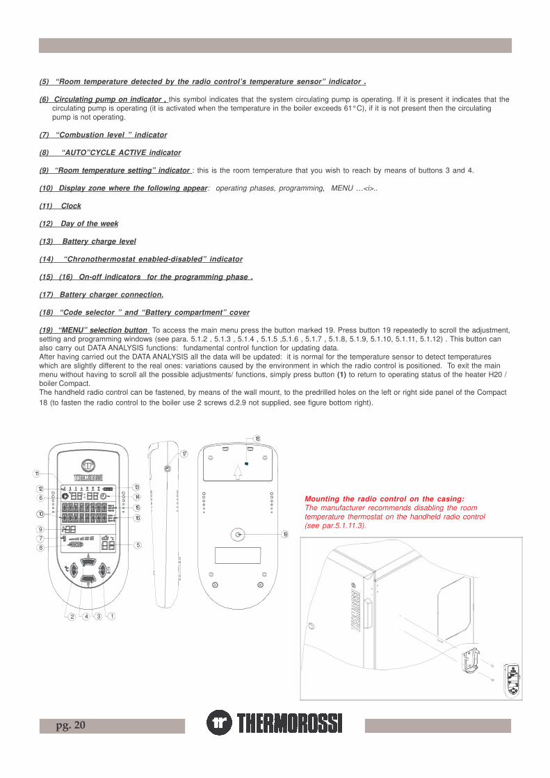
(5) “Room temperature detected by the radio control’s temperature sensor” indicator .
(6) Circulating pump on indicator , this symbol indicates that the system circulating pump is operating. If it is present it indicates that thecirculating pump is operating (it is activated when the temperature in the boiler exceeds 61°C), if it is not present then the circulatingpump is not operating.
(7) “Combustion level ” indicator
(8) “AUTO”CYCLE ACTIVE indicator
(9) “Room temperature setting” indicator : this is the room temperature that you wish to reach by means of buttons 3 and 4.
(10) Display zone where the following appear: operating phases, programming, MENU …<i>..
(11) Clock
(12) Day of the week
(13) Battery charge level
(14) “Chronothermostat enabled-disabled” indicator
(15) (16) On-off indicators for the programming phase .
(17) Battery charger connection.
(18) “Code selector ” and “Battery compartment” cover
(19) “MENU” selection button To access the main menu press the button marked 19. Press button 19 repeatedly to scroll the adjustment,setting and programming windows (see para. 5.1.2 , 5.1.3 , 5.1.4 , 5.1.5 ,5.1.6 , 5.1.7 , 5.1.8, 5.1.9, 5.1.10, 5.1.11, 5.1.12) . This button canalso carry out DATA ANALYSIS functions: fundamental control function for updating data.After having carried out the DATA ANALYSIS all the data will be updated: it is normal for the temperature sensor to detect temperatureswhich are slightly different to the real ones: variations caused by the environment in which the radio control is positioned. To exit the mainmenu without having to scroll all the possible adjustments/ functions, simply press button (1) to return to operating status of the heater H20 /boiler Compact.The handheld radio control can be fastened, by means of the wall mount, to the predrilled holes on the left or right side panel of the Compact18 (to fasten the radio control to the boiler use 2 screws d.2.9 not supplied, see figure bottom right).
Mounting the radio control on the casing:The manufacturer recommends disabling the roomtemperature thermostat on the handheld radio control(see par.5.1.11.3).
pg. 21
20 Red push button: press and hold down for approx. 2 seconds toincrease the combustion power. One or more acoustic signals correspondto each power step selected:
-1 power bar - - 1 acoustic signal -2 power bars - - 2 acoustic signals -........................................................................ -5 power bars - - 5 acoustic signals
If you press once again the acoustic signals will not sound: this meansthat after 5 seconds the heater / boiler will set itself in OFF mode andconsequently shut down. It is not possible to select the AUTO cycle.The radio control, several minutes after the last power variation, executesa DATA ANALYSIS then displays the new setting.
21 Loudspeaker for voice alarms/information: the heater / boiler givesinformation on its status and any active alarms through this loudspeaker.
22 Power outlet for additional room temperature connection.(seepara. 6.1)
(additional room temperature thermostat not supplied ))
23 Power outlet for additional chronothermostat connection.(seepara. 6.2)
(additional chronothermostat not supplied )
24 Overtemperature thermostat button cap.In the event of overtemperature this safety thermostat stops the loading of pellets. When it is activated LED 27 comes on. To restart theheater you have to wait until the water inside it cools down, then verify the cause for the overheating, remove the cause, unscrew theprotective cap and press the button (24).
25 Electrical power outlet for heater / boiler 220-240V 50Hz.
26 Loading motor test LED. The light must come on when the pellet screw feeder starts.
27 Reset thermostat tripped indicator light. This LED comes on when the reset thermostat is activated.
28 Main switch 0-1
29 General fuse 3.15 A.
29
25
24
23
22
2021
27
28
26
5.1.1.3 HEA5.1.1.3 HEA5.1.1.3 HEA5.1.1.3 HEA5.1.1.3 HEATER / BOILER BTER / BOILER BTER / BOILER BTER / BOILER BTER / BOILER BAAAAACK PCK PCK PCK PCK PANELANELANELANELANEL
5.1.1.4 BUTTON 19, MENU AND FUNCTIONS5.1.1.4 BUTTON 19, MENU AND FUNCTIONS5.1.1.4 BUTTON 19, MENU AND FUNCTIONS5.1.1.4 BUTTON 19, MENU AND FUNCTIONS5.1.1.4 BUTTON 19, MENU AND FUNCTIONS
Button 19 allows you to access a MENU where you can make full use of all the radio control functions.When the button is pressed repeatedly the following words appear in sequence :
TIME .. to set the day of the week the hour and minutes.
CHRONO .. to set the chronothermostat.
BAR .. to view the water pressure in the boiler.
VOLUME .. to set the volume level for the vocal alarms.
LANGUAGE .. to select the language (Italian, English...)
SUMMER .. to operate the boiler in summer mode (only with optional domestic hot water kit, see par.5.1.8).
LEVEL .. to vary the rotating speed of the smoke suction unit, the fuel consumption does not change.
DATA ANALYSIS updates and exchanges data between the generator and the radio control
To access the functions in each submenu press the left button (2), edit the parameter with buttons (3) and (4), and confirm by pressingbutton (1).

pg. 22
5.1.2 D5.1.2 D5.1.2 D5.1.2 D5.1.2 DAAAAAY Y Y Y Y AND AND AND AND AND TIME SETTINGTIME SETTINGTIME SETTINGTIME SETTINGTIME SETTING
The heater / boiler must be energised and the switch at the back turned toposition “1”(see image 5.1.1.3 ).To set the clock and the day of the week carry out the procedures describedbelow. Press the button (19) on the back of the radio control until the word TIMEappears. Press the button (2). The word DAYS will appear on the display, andthe indicator (12) will start to blink.Press the button (3) and/or (4) to set the number that corresponds to the currentday. The symbol corresponds to Monday , the symbol to Tuesday .....
and the symbol to Sunday. To confirm the selection press the right button(1). Next the word HOUR will appear on the display, and the hour indicator (11)will start to blink. Press button (3) and/or (4) to set the current time. To confirmthe selection press the button (1). Next the word MINUTES will appear on thedisplay and the minute indicator (11) will start to blink. Press buttons (3) and/or(4) to set the current minutes . To confirm the selection press the button (1). Theday and time setting is now completed : at this point the heater / boiler operatingstatus will appear on the display.
2 4 3 1
10
78
9
126
11
5
16
15
14
13
19
5.1.3 CHR5.1.3 CHR5.1.3 CHR5.1.3 CHR5.1.3 CHRONOONOONOONOONOTHERMOSTTHERMOSTTHERMOSTTHERMOSTTHERMOSTAAAAATTTTT::::: ON/OFF PR ON/OFF PR ON/OFF PR ON/OFF PR ON/OFF PROGRAMMINGOGRAMMINGOGRAMMINGOGRAMMINGOGRAMMING.....
The heater / boiler must be energised and the switch at the back turned to position“1”. The weekly programming can be executed with the help of the handheld radiocontrol. It is possible to set up to 3 on-off cycles for each day from Monday toSunday.To access the programming mode press the button (19) on the back of the radiocontrol repeatedly until the word CRONO appears. Press button (3) or (4) to enable/disable the program setting ( symbol (14) present / absent): this function is useful ifyou wish to disable the established weekly program setting.To program the heater / boiler you need to access the chronothermostat function bypressing the button (2): the LED (12) comes on (this indicates that Monday, thefirst day of the week, is being programmed).The text ON1 of the indicator (15) comes on and the word HOURS appears on thedisplay.Press button (3) and/or (4) to enter the hour of the first cycle start time. To confirmthe selection press the button (1). The word MINUTES will appear on the display.Press button (3) and/or (4) to enter the minutes of the first cycle start time. To confirmthe selection press the button (1). Next the text OFF1 (indicator (16) will appear onthe display. Proceed using buttons (3), (4) and (1) as indicated above to set HOURSand MINUTES for the cycle end time. At this point the first on-off cycle for Mondayhas been entered. It is then possible to set the second on-off cycle for Monday(indicated by the texts ON2 and OFF2) and the third on-off cycle for Monday(indicated by the texts ON3 and OFF3) . Now program the on-off cycles for theremaining days of the week up to and including Sunday. When the programming mode
is active ( symbol present) the minimum operating value at cycle on (combustion power - ventilation speed ) is the same minimumoperating value that was set before the last cycle off.If the second on-off cycle is not required simply set the ON2 time as 00:00 and the OFF2 time as 00:00 .
In the event of a programmed cycle on always ensure that the brazier is clean: failure to keep the brazier clean can reduce the lifeof the spark plug.
2 4 3 1
10
7
8
9
126
11
5
16
15
14
13
19
pg. 23
5.1.4 5.1.4 5.1.4 5.1.4 5.1.4 VVVVVOICE INFORMAOICE INFORMAOICE INFORMAOICE INFORMAOICE INFORMATION TION TION TION TION VVVVVOLOLOLOLOLUME CONTRUME CONTRUME CONTRUME CONTRUME CONTROLOLOLOLOL
The heater / boiler must be energised and the switch at the back turned to position “1”.Your heater / boiler informs you on its operating status and on any problems that could arise by means of voice messages. Select the volumelevel for the voice messages by carrying out the following procedure. When the insert is in the POWER OFF, POWER ON or RUNNING statussimply press the button (19) until the word VOLUME appears on the display (10). Press button (2) and the word SELECT appears on thedisplay:the introductory music plays. Press button (4) repeatedly and the + symbol appears (to increase the volume) . Press button (3)repeatedly and the - symbol appears (to lower the volume). To confirm the volume selection press the button (1). The heater then returns toits previous POWER ON or RUNNING or POWER OFF status.
5.1.5 LANGU5.1.5 LANGU5.1.5 LANGU5.1.5 LANGU5.1.5 LANGUAAAAAGE SELECTIONGE SELECTIONGE SELECTIONGE SELECTIONGE SELECTION
The heater / boiler must be energised and the switch at the back turned to position “1”.Press the MENU’ button (19) repeatedly until the word ITALIAN appears on the display (10) . To change the display language proceed asfollows: Press button (2) and the SELECT ITALIAN text appears on the display. Press the button (4) repeatedly to select German, English,French, Spanish. Once you have selected the desired language press button (1) : The handheld radio control carries out a data analysis, thatis, an update of the new language.
5.1.6 OPERA5.1.6 OPERA5.1.6 OPERA5.1.6 OPERA5.1.6 OPERATING LEVEL SETTINGTING LEVEL SETTINGTING LEVEL SETTINGTING LEVEL SETTINGTING LEVEL SETTING
The heater / boiler must be energised and the switch at the back turned to position “1”.Your appliance is delivered with an excellent program installed that favours combustion yield; the program is called Level 1.If you are using pellets with a higher than normal incidence of residues after combustion in the brazier, alternative levels may be selected:
Level 2 : this program increases the smoke suction unit speed acceleration.Level 0 : when using lightly-compressed pellets and/or flue outlets with very high vacuum, over 2 mm water column.
The pellet consumption value is not affected by the operating level settings.Select the required level by acting as follows:Press the (19) button on the back of the radio control repeatedly until the text indicating the preset heater / boiler level appears on thedisplay.(Level 1 or Level 2 ). Press the button (2) and the word SELECT appears on the display (10). To change the operating level holddown button (3) and press button (4). By holding down button (3) and pressing button (4) repeatedly the level changes in the followingsequence: Level 2... ...Level 1.
5.1.7 5.1.7 5.1.7 5.1.7 5.1.7 WWWWWAAAAATER PRESSURE IN TER PRESSURE IN TER PRESSURE IN TER PRESSURE IN TER PRESSURE IN THE GENERATHE GENERATHE GENERATHE GENERATHE GENERATTTTTOROROROROR
The water pressure in the generator can be viewed on the radio control, see par. 5.2.
The level selection can be made with the heater / boiler OFF or ON. If the change is made while the insert is running thedifference in the flame will be apparent. It is mandatory to pay particular care when selecting the most appropriateoperating cycle for your installation. After the selection of the operating cycle a thorough cleaning of the brazier ismandatory.

pg. 24
2 4 3 1
10
7
8
9
126
11
5
16
15
14
13
19
5.1.85.1.85.1.85.1.85.1.8 DOMESTIC HODOMESTIC HODOMESTIC HODOMESTIC HODOMESTIC HOT T T T T WWWWWAAAAATER PRTER PRTER PRTER PRTER PRODUCTION (SUMMERODUCTION (SUMMERODUCTION (SUMMERODUCTION (SUMMERODUCTION (SUMMERCYCYCYCYCYCLE) .CLE) .CLE) .CLE) .CLE) .
With this function it is possible, independently from all other factors, switch thediverting valve of the Domestic hot water kit (optional) permanently to the plateheat exchanger (see par. 4.10): in the SUMMER CYCLE the heat produced bythe heater / boiler is used exclusively to produce domestic hot water. The boilerpump is activated when the temperature exceeds 61°C.To view and either enable or disable the SUMMER CYCLE function press button(19) at the back of the radio control until the text “ SUMMER OFF” appears.Press button (3) and/or button (4) to enable or disable the SUMMER CYCLE. Toquit this menu press button (19) repeatedly until the text DATA ANALYSISappears.
One of the following will appear on the display:
SUMMER ON ——> the heat is transmitted exclusively to the plateheat exchanger.
SUMMER OFF ——> the heat is transmitted to the plant generatordelivery with priority to the plate heatexchanger (optional) when present.
5.1.95.1.95.1.95.1.95.1.9 DDDDDAAAAATTTTTA A A A A ANANANANANALALALALALYYYYYSISSISSISSISSIS
The radio control and the heater / boiler interact systematically and regularly : this interchange of data is referred to as DATA ANALYSIS.This is a function that is regularly activated by the radio control to update values such as : temperatures, operating modes, activation of thecirculating pump.....etc. The updating takes place regularly and often for the most important values such as water temperature in thegenerator, whereas for less important values such as room temperature it takes place every few minutes.It may be that the values appearing on the display do not correspond to the state of the heater / boiler: this situation is completely normal and itis corrected as soon as the DATA ANALYSIS function is activated.Press button (19) repeatedly to execute the DATA ANALYSIS. The updating process involves all the variables if button (19), when the wordsDATA ANALYSIS appear, is held down for at least one second. If the DATA ANALYSIS is not successful, repeat the operation by holding downbutton (19) for a few seconds and then releasing it. The DATA ANALYSIS process can take from a minimum of 10 seconds to a maximum of40 seconds.The duration is variable because it depends on the type of disturbances (radio wave frequencies, electromagnetic disturbances, etc...)present in the environment.If the electromagnetic disturbances present in the environment exceed those permitted by EC type approval standards and legislation forappliances the manufacturer declines all responsibility for any appliance that does not perform to optimal levels.
Examples of activation of the DATA ANALYSIS function:
-If the combustion power variation occurs through the manual control (par. 5.1.1.3) installed at the back of the heater / boiler, a few minuteslater the radio control executes a DATA ANALYSIS and displays the new settings.
-If the data transmission codes need to be changed (par. 10) to make the variations effective it is mandatory to execute a DATA ANALYSIS byholding down button (19) for at least one second.
pg. 25
5.1.105.1.105.1.105.1.105.1.10 TRANSMISSION - RECEPTION ALARMSTRANSMISSION - RECEPTION ALARMSTRANSMISSION - RECEPTION ALARMSTRANSMISSION - RECEPTION ALARMSTRANSMISSION - RECEPTION ALARMS
If a problem arises with the communication between the handheld radio control and the heater / boiler the following messages could appearon the display:
OFF : the radio control is located at a distance that is greater than the radio control’s radius of action. It is quite possible and normalfor external causes to make this word appear monomentarily while the heater is operating.
OFF : the heater / boiler has shut down and does not appear to be powered by electricity.
5.1.115.1.115.1.115.1.115.1.11 INFORMAINFORMAINFORMAINFORMAINFORMATION TION TION TION TION ABOUT HOABOUT HOABOUT HOABOUT HOABOUT HOW W W W W THE GENERATHE GENERATHE GENERATHE GENERATHE GENERATTTTTOR OR OR OR OR WWWWWORKSORKSORKSORKSORKS
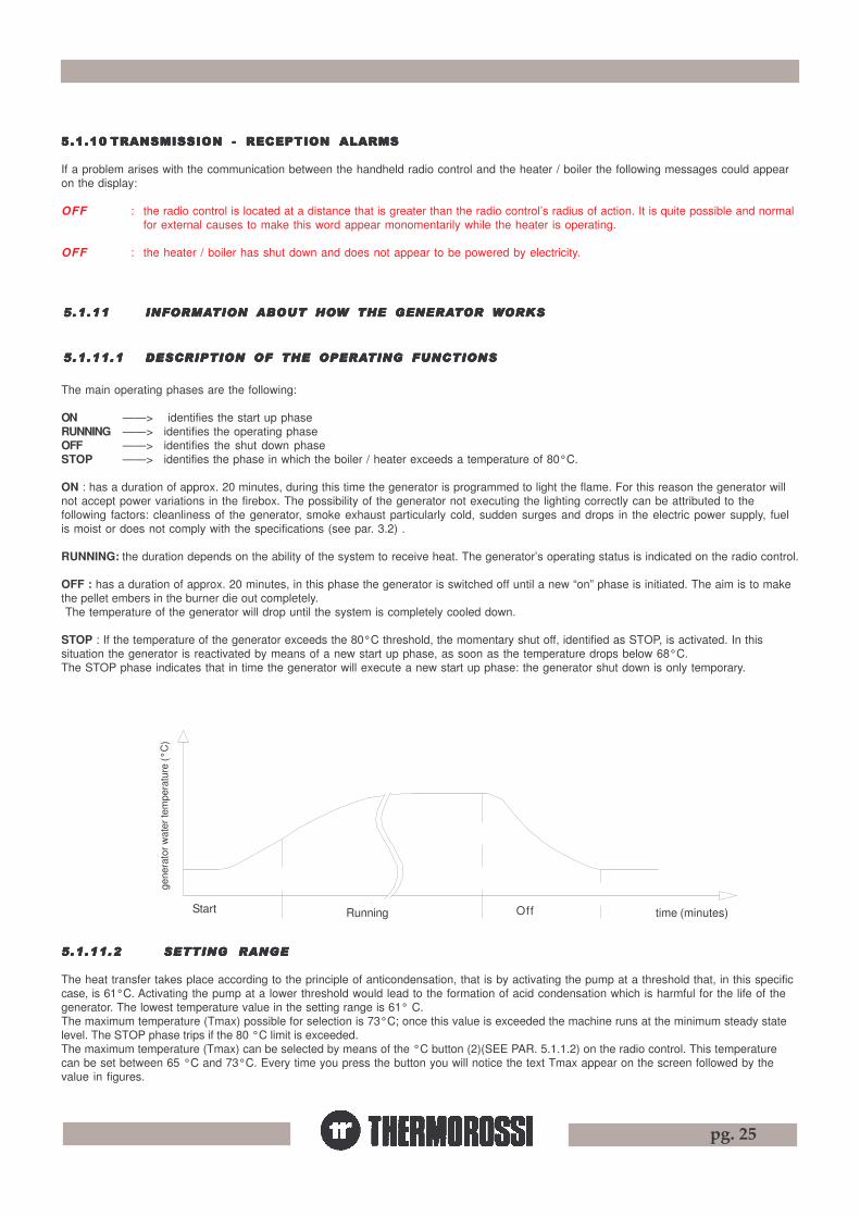
5.1.11.15.1.11.15.1.11.15.1.11.15.1.11.1 DESCRIPTION OF DESCRIPTION OF DESCRIPTION OF DESCRIPTION OF DESCRIPTION OF THE OPERATHE OPERATHE OPERATHE OPERATHE OPERATING FUNCTIONSTING FUNCTIONSTING FUNCTIONSTING FUNCTIONSTING FUNCTIONS
5.1.11.25.1.11.25.1.11.25.1.11.25.1.11.2 SETTING RANGESETTING RANGESETTING RANGESETTING RANGESETTING RANGE
The heat transfer takes place according to the principle of anticondensation, that is by activating the pump at a threshold that, in this specificcase, is 61°C. Activating the pump at a lower threshold would lead to the formation of acid condensation which is harmful for the life of thegenerator. The lowest temperature value in the setting range is 61° C.The maximum temperature (Tmax) possible for selection is 73°C; once this value is exceeded the machine runs at the minimum steady statelevel. The STOP phase trips if the 80 °C limit is exceeded.The maximum temperature (Tmax) can be selected by means of the °C button (2)(SEE PAR. 5.1.1.2) on the radio control. This temperaturecan be set between 65 °C and 73°C. Every time you press the button you will notice the text Tmax appear on the screen followed by thevalue in figures.
The main operating phases are the following:
ON ——> identifies the start up phaseRUNNING ——> identifies the operating phaseOFF ——> identifies the shut down phaseSTOP ——> identifies the phase in which the boiler / heater exceeds a temperature of 80°C.
ON : has a duration of approx. 20 minutes, during this time the generator is programmed to light the flame. For this reason the generator willnot accept power variations in the firebox. The possibility of the generator not executing the lighting correctly can be attributed to thefollowing factors: cleanliness of the generator, smoke exhaust particularly cold, sudden surges and drops in the electric power supply, fuelis moist or does not comply with the specifications (see par. 3.2) . RUNNING: the duration depends on the ability of the system to receive heat. The generator’s operating status is indicated on the radio control.
OFF : has a duration of approx. 20 minutes, in this phase the generator is switched off until a new “on” phase is initiated. The aim is to makethe pellet embers in the burner die out completely. The temperature of the generator will drop until the system is completely cooled down. STOP : If the temperature of the generator exceeds the 80°C threshold, the momentary shut off, identified as STOP, is activated. In thissituation the generator is reactivated by means of a new start up phase, as soon as the temperature drops below 68°C.The STOP phase indicates that in time the generator will execute a new start up phase: the generator shut down is only temporary.
Temp
erat
ura
acqu
a ge
nera
tore
(°c)
LavoroAvvio Off tempo (minuti)Start Running Off time (minutes)
gene
rato
r wat
er te
mpe
ratu
re (°
C)

pg. 26
The temperature readout is indicated by the symbol (5) ; the required room temperature can beadjusted by means of buttons (3) and (4). During the start up phase the temperature value is notupdated. The temperature value transmitted to the heater / boiler does not change instantly whenthere are sudden changes in the room temperature, but it is updated regularly every 4 minutes orso.When the room temperature reaches the value set in the thermostat the appliance runs at theminimum power level (indicated by the appearance of a black bar). The power can, however, beincreased and switched off by simply disabling the thermostat. If the temperature limit of 80 °C isreached in the generator in minimum position, the STOP function is activated to avoid excessiveoverheating and system malfunctions.
Important : The room temperature thermostat can be disabled. To disable thethermostat simply press on the setting button until OFF appears and replaces the settemperature. Important : If you have a Compact generator we recommend positioningthe radio control near the generator. In this case detecting the temperature in the heatcontrol unit is unnecessary, consequently the thermostat should be disabled.
5.1.11.45.1.11.45.1.11.45.1.11.45.1.11.4 AAAAAUTUTUTUTUTOMAOMAOMAOMAOMATIC OPERATIC OPERATIC OPERATIC OPERATIC OPERATING CYTING CYTING CYTING CYTING CYCLECLECLECLECLE
In the automatic operating cycle the generator expresses its maximum flexibility of operation while optimising fuel consumption. To activatethe AUTO cycle, select the power bars until the word AUTO appears. During the AUTO cycle the heater / boiler self-regulatesthe combustion according to the water temperature in the boiler set with button (2) . If for example the temperature ( Tmax) is set at 70°C thefive speed levels will be automatically distributed between 61°C and 70°C so that with a temperature set at 70°C the heater / boiler is at itsminimum power level. The minimum level can be adjusted by means of button (2). If the t max value is increased or reduced by means ofbutton (2) all the power levels will be redistributed along the full temperature range. We therefore recommend finding the best Tmax value inorder to optimise the full potential of the produced heat.If for example the Tmax is set at a high temperature, let’s say 73°C, the appliance will attempt to reach that level as quickly as possible bymodulating the power as it approaches the set temperature. It is not necessary to set high t max temperatures when the ambient conditionsdo not require them. Time and experience in using the appliancewill give you the possibility of determining which are the most appropriate SET POINTS for your needs. If the combustion power is notabsorbed by the system above a temperature of 80° C the appliance will temporarily shut down and the word STOP will appear in thedisplay. Reactivation will occur automatically when the temperature drops to 68°C.
5.1.11.35.1.11.35.1.11.35.1.11.35.1.11.3 RRRRROOM OOM OOM OOM OOM TEMPERATEMPERATEMPERATEMPERATEMPERATURE TURE TURE TURE TURE THERMOSTTHERMOSTTHERMOSTTHERMOSTTHERMOSTAAAAATTTTT
One of the numerous functions of the radio control is the possibility of detecting the temperature in the zone where it is located. Werecommend using the wall mount to prevent accidental falls and subsequent damage not covered by warranty.The thermostat has the following important function :It interrupts operation of the circulating pump and sets the heater / boiler at the minimum steady state power level once the preset temperaturehas been reached. The temperature setting must take into account the influence of the lighting of the display backlighting that temporarilyoffsets the real temperature reading by a few degrees; the correct reading value will appear approximately 40 minutes after the displayswitches off. The temperature value detected by the room temperature thermostat compared to the real value can vary by ± 1.5 °C. Even theplacement of the thermostat in a particular position can influence the real reading of the temperature.
2 4 3 1
9
5
5 4 3 2 1
61 °c 70 °c 80 °c
STOPPotenza di funzionamento
Intervallo modulazione con T max 70°c
Operating power
Modulation frequency with Tmax 70°C
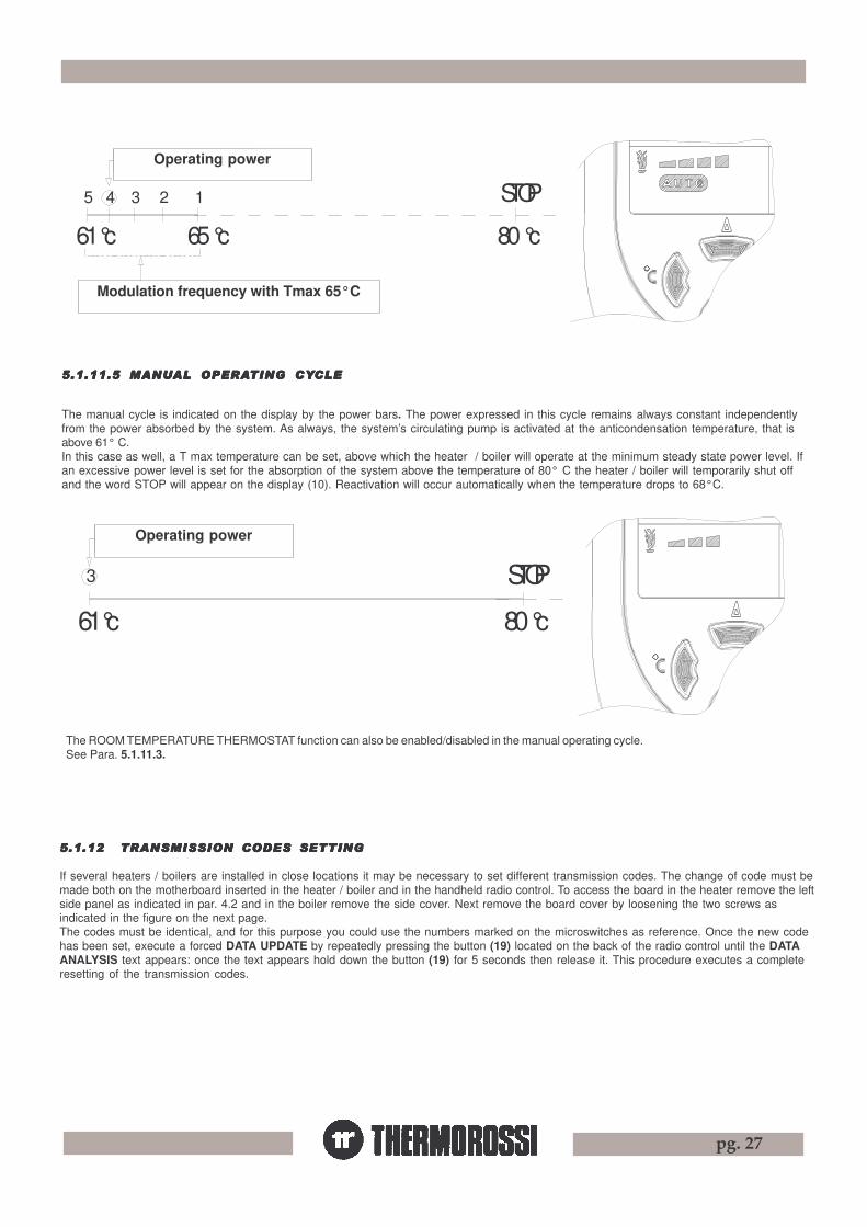
pg. 27
5.1.12 TRANSMISSION CODES SETTING5.1.12 TRANSMISSION CODES SETTING5.1.12 TRANSMISSION CODES SETTING5.1.12 TRANSMISSION CODES SETTING5.1.12 TRANSMISSION CODES SETTING
If several heaters / boilers are installed in close locations it may be necessary to set different transmission codes. The change of code must bemade both on the motherboard inserted in the heater / boiler and in the handheld radio control. To access the board in the heater remove the leftside panel as indicated in par. 4.2 and in the boiler remove the side cover. Next remove the board cover by loosening the two screws asindicated in the figure on the next page.The codes must be identical, and for this purpose you could use the numbers marked on the microswitches as reference. Once the new codehas been set, execute a forced DATA UPDATE by repeatedly pressing the button (19) located on the back of the radio control until the DATAANALYSIS text appears: once the text appears hold down the button (19) for 5 seconds then release it. This procedure executes a completeresetting of the transmission codes.
The manual cycle is indicated on the display by the power bars. The power expressed in this cycle remains always constant independentlyfrom the power absorbed by the system. As always, the system’s circulating pump is activated at the anticondensation temperature, that isabove 61° C.In this case as well, a T max temperature can be set, above which the heater / boiler will operate at the minimum steady state power level. Ifan excessive power level is set for the absorption of the system above the temperature of 80° C the heater / boiler will temporarily shut offand the word STOP will appear on the display (10). Reactivation will occur automatically when the temperature drops to 68°C.
5.1.11.5 MANU5.1.11.5 MANU5.1.11.5 MANU5.1.11.5 MANU5.1.11.5 MANUAL OPERAAL OPERAAL OPERAAL OPERAAL OPERATING CYTING CYTING CYTING CYTING CYCLECLECLECLECLE
Intervallo modulazione con T max 65°c
Potenza di funzionamento
61 °c
5 4 3
65 °c
2 1
80 °c
STOP
Potenza di funzionamento
61 °c 80 °c
STOP3
The ROOM TEMPERATURE THERMOSTAT function can also be enabled/disabled in the manual operating cycle.See Para. 5.1.11.3.
Operating power
Modulation frequency with Tmax 65°C
Operating power
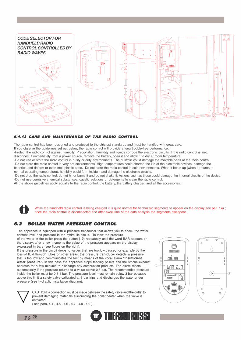
pg. 28
19
10
The appliance is equipped with a pressure transducer that allows you to check the watercontent level and pressure in the hydraulic circuit. To view the pressureof the water in the boiler press the button (19) repeatedly until the word BAR appears onthe display: after a few moments the value of the pressure appears on the displayexpressed in bars (see figure on the right).If the pressure in the circuit drops to values that are too low caused for example by theloss of fluid through tubes or other areas, the pressure transducer detects a pressurethat is too low and communicates the fact by means of the vocal alarm “Insufficientwater pressure”. In this case the appliance stops feeding pellets and the smoke exhaustoperates for a few minutes to discharge any combustion products. The alarm resetsautomatically if the pressure returns to a value above 0.3 bar. The recommended pressureinside the boiler must be 0.8-1 bar. The pressure level must remain below 3 bar becauseabove this limit a safety valve calibrated at 3 bar trips and discharges the water underpressure (see hydraulic installation diagram).
5.25.25.25.25.2 BOILER BOILER BOILER BOILER BOILER WWWWWAAAAATER PRESSURE CONTRTER PRESSURE CONTRTER PRESSURE CONTRTER PRESSURE CONTRTER PRESSURE CONTROLOLOLOLOL
5.1.13 CARE AND MAINTENANCE OF THE RADIO CONTROL5.1.13 CARE AND MAINTENANCE OF THE RADIO CONTROL5.1.13 CARE AND MAINTENANCE OF THE RADIO CONTROL5.1.13 CARE AND MAINTENANCE OF THE RADIO CONTROL5.1.13 CARE AND MAINTENANCE OF THE RADIO CONTROL
The radio control has been designed and produced to the strictest standards and must be handled with great care.If you observe the guidelines set out below, the radio control will provide a long trouble-free performance:-Protect the radio control against humidity! Precipitation, humidity and liquids corrode the electronic circuits. If the radio control is wet,disconnect it immediately from a power source, remove the battery, open it and allow it to dry at room temperature.-Do not use or store the radio control in dusty or dirty environments. The dust/dirt could damage the movable parts of the radio control.-Do not store the radio control in very hot environments. High temperatures could shorten the life of the electronic devices, damage thebatteries and deform or even melt plastic parts. -Do not store the radio control in cold environments. When it heats up (when it returns tonormal operating temperature), humidity could form inside it and damage the electronic circuits.-Do not drop the radio control, do not hit or bump it and do not shake it. Actions such as these could damage the internal circuits of the device.-Do not use corrosive chemical substances, caustic solutions or detergents to clean the radio control.All the above guidelines apply equally to the radio control, the battery, the battery charger, and all the accessories.
ON
21 1
2
ON
ON12
SELETTORE CODICI PER RADIOCOMANDO PALMARE
ON
12
ON
1 2
GESTITO VIA ONDE RADIO
While the handheld radio control is being charged it is quite normal for haphazard segments to appear on the display(see par. 7.4) ;once the radio control is disconnected and after execution of the data analysis the segments disappear.
CODE SELECTOR FORHANDHELD RADIOCONTROL CONTROLLED BYRADIO WAVES
CAUTION: a connection must be made between the safety valve and the outlet toprevent damaging materials surrounding the boiler/heater when the valve isactivated( see para. 4.4 , 4.5 , 4.6 , 4.7 , 4.8 , 4.9 ).

pg. 29
5.35.35.35.35.3 SWITSWITSWITSWITSWITCHING ON CHING ON CHING ON CHING ON CHING ON THE HEATHE HEATHE HEATHE HEATHE HEATER H2O / BOILER COMPTER H2O / BOILER COMPTER H2O / BOILER COMPTER H2O / BOILER COMPTER H2O / BOILER COMPAAAAACTCTCTCTCT
Before using the heater / boiler check that all the movable parts are in place; also remove any labels and stickers from the glassto avoid having permanent traces remain on the surfaces. Verify that the electric and hydraulic connections have been madeperfectly. Check also (during all the operating phases) that the firebox door and the ash pans are always firmly closed.
Then carry out the following operations:- Check that the hydraulic system has been correctly executed and has an adequate closed expansion tank to guarantee maximum safety.
The expansion must be calculated as specified in UNI 10412/2. Any damage to the plant and/or appliance will not be covered by warranty.The presence of the expansion tank in the heater / boiler guarantees protection against thermal expansion only andexclusively of the heater / boiler.
- Power up the appliance and turn the switch installed at the back of the heater / boiler to position "1" (= ON). Make sure that the batteries ofthe handheld radio control are charged (the symbol indicates that the batteries are charged). If the batteries are flat charge themusing the battery charger provided for 12 hours.
- Fill the system using the inlet tap (see par. 4.3 , 4.4 , 4.5 , 4.6 , 4.7 , 4.8 , 4.9 , 4.10, 4.11).- Do not overdo the pressure in the appliance during the make-up phase : max pressure 1 bar. The reading of the pressure is executed as
explained in para. 5.2.- The water fill phase must be simultaneous with the air purge. The purge operation is carried out using a screwdriver or a punch on the
purge valve (to accelerate the system filling times)( see par. 4.3 ).- Connect the smoke exhaust to the appliance : we recommend against using aluminium tubes and we recommend always using sealing
gaskets. Further information is given in paragraph 8 of this use and maintenance booklet.- Load the pellets into the hopper .- Press the button (1) to begin the start up phase and the word ON will appear on the display. Press the button (1) repeatedly to set the
appliance in AUTO or manual operating mode. The mode will be activated at the end of the start up phase. Press button (2) to adjust thewater temperature in the boiler that you wish to reach (see par. 5.1). During the 20 minutes of the start up phase any set thermal powerlevel is ignored to deal with correct fill up and suction values preset by the Manufacturer. The electric heater will begin to heat up and afew minutes after the start of operation the first pellet feed will begin. This occurs because the screw feeder has to fill up because it iscompletely empty. The first time the heater / boiler is started up the start up phase will have to be carried out twice for this very reason.Before beginning the second start up phase empty and vacuum the brazier.
- Once again check the pressure inside the appliance and if necessary purge any existing air bubbles from the valve provided for thispurpose.
CAUTION : The start up phase (word ON appearing on the display) takes approx. 20 minutes during which the heater / boiler ignoresany commands transmitted to it. After this time has elapsed the word RUNNING appears on the display.When the machine is in the running phase the combustion can be adjusted manually or in AUTO mode.
CAUTION : The circulator pump begins operating as soon as the temperature in the boiler reaches 61°C.CAUTION : If the appliance does not start up correctly check that the brazier and electric heater are clean. It is extremelyimportant to ensure that the tube lodging of the electric heater is clean; there must be no deposits or dust. The operation mustbe carried out with a good vacuum cleaner.
5.45.45.45.45.4 ADJUSTING ADJUSTING ADJUSTING ADJUSTING ADJUSTING THE COMBTHE COMBTHE COMBTHE COMBTHE COMBUSTION OF USTION OF USTION OF USTION OF USTION OF THE HEATHE HEATHE HEATHE HEATHE HEATER H2O / BOILER COMPTER H2O / BOILER COMPTER H2O / BOILER COMPTER H2O / BOILER COMPTER H2O / BOILER COMPAAAAACTCTCTCTCT
The thermal value is adjusted through 2 buttons (1) and (2) described in para. 5.1.
5.4.1 COMBUSTION ADJUSTMENT IN MANUAL MODE (see para. 5.1.11.5).
5.4.2 COMBUSTION ADJUSTMENT IN AUTOMATIC MODE (see para. 5.1.11.4).
CAUTION : The manufacturer denies all responsibility for the life of the electrical heater if subjected to excessive start ups. It isadvisable, therefore, to set the correct power level to avoid this danger.
5.5 SHUTTING OFF 5.5 SHUTTING OFF 5.5 SHUTTING OFF 5.5 SHUTTING OFF 5.5 SHUTTING OFF THE HEATHE HEATHE HEATHE HEATHE HEATER H2O / BOILER COMPTER H2O / BOILER COMPTER H2O / BOILER COMPTER H2O / BOILER COMPTER H2O / BOILER COMPAAAAACTCTCTCTCT
To shut off the heater / boiler simply zero the power bars on the display.DO NOT shut off the heater by disconnecting the generator from the electric power outlet. This operation could generate smoke that may notbe evacuated due to the construction characteristics of your system’s smoke discharge tube and chimney.The shut down time for the smoke exhaust is roughly 25 minutes.
While the handheld radio control is being charged it is quite normal for haphazard segments to appear on the display(see par. 7.4) ;once the radio control is disconnected and after execution of the data analysis the segments disappear.
pg. 30
6 ADDITIONAL ROOM TEMPERATURE THERMOSTAT / ADDITIONAL CHRONOTHERMOSTAT(not supplied)
The handheld radio control ensures that your heater / boiler is provided with all the requiredprogramming and temperature adjustment functions:
Two connectors are located on the back of the heater / boiler near the electric power socket.They refer to two operating modes:à With the room temperature thermostat. à With the chronothermostat or modem.Procure a jack where the 2 wires are to be welded as illustrated in the diagram:Use only contacts 1 and 2, do not use contact 3.
Contacts 1-2 are defined as “CLEAN” contacts and they must never be fed with 220 V. If theboard is energised with 220V or with voltages exceeding 6 V the control board will be permanently damaged and will not becovered by the GUARANTEE.
6.1 OPERATING WITH THE ADDITIONAL ROOM TEMPERATURE THERMOSTAT (NOT SUPPLIED )
It is possible to install an additional room temperature thermostat by connecting it to the back of the heater / boiler, by inserting a jack in thesocket marked “THERMOSTAT” (see drw. para. 5.1.1.3). This is a stereo jack, it is not supplied with the heater / boiler but is readily availablein electrical or stereophonic equipment stores. It has a clean contact, that is a low voltage contact. The operating principle is as follows:-When the environment reaches the set temperature the thermostat closes the contact and the heater / boiler runs at the minimum combustion
power: the situation is described by the appearance of the 1st power bar on the display. Simultaneously, the circulator pump is shut off anda few minutes later the symbol disappears from the display on the radio control.
-When the room temperature drops the thermostat opens the contact and the heater / boiler returns to its original position in terms of thermalpower.
Caution: N.C. (normally closed) contacts must be used for the connection to the additional room temperature thermostat. Contacts1-2 of the cronothermostat mod. “Perry”. Do not energise with 220V as this will irreparably damage the control board.
CAUTION: In the event of connections to the chronothermostat Thermorossi shall not be held responsible for the heater not starting up,smoke leaks, breakage of the lighting component. In the event of a programmed cycle on always ensure that the brazier is clean:
.6.2 OPERATING WITH THE ADDITIONAL CHRONOTHERMOSTAT (NOT SUPPLIED )
It is possible to install, as an alternative to the room thermostat, a chronothermostat that must be connected by means of a jack to the back ofthe heater / boiler in the socket marked “CHRONOTHERMOSTAT” (see drw. para.5.1.1.3). Using this outlet when the chronothermostatcontact closes the ON cycle starts, whereas when the contact opens the OFF cycle starts. When the chronothermostat is active, theappliance can not be shut off except from the additional chronothermostat.
CAUTION: The manufacturer denies all responsibility for the life of the electrical heater if subjected to excessive start ups.Consequently, it is advisable to set the chronothermostat appropriately to avoid this danger .CAUTION: Use N.O. (normally open) contacts for the connection to the chronothermostat. Contacts 1-3 of the cronothermostatmod. “Perry”. Do not energise with 220V as this will irreparably damage the control board.
5.6 SETTING THE ROOM TEMPERATURE THERMOSTAT H2O / COMPACT
For the management of the thermostat see para. 5.1.11.3.

pg. 31
77777 CLEANING AND MAINTENANCECLEANING AND MAINTENANCECLEANING AND MAINTENANCECLEANING AND MAINTENANCECLEANING AND MAINTENANCE
7.17 .17 .17 .17 .1 FOREWORDFOREWORDFOREWORDFOREWORDFOREWORD
Before beginning any maintenance operation ensure that the appliance is in the OFF phase and disconnect it from the electric poweroutlet.
Your pellet heater / boiler ECOTHERM is a solid fuel generator : it requires frequent controls and general cleaning operations. This willguarantee regular operation and optimal output at all times. If the product is unused for a prolonged period of time it is mandatory toinspect the smoke channel and outlet to ensure that there are no obstructions before use .
7.27 .27 .27 .27 .2 CLEANING CLEANING CLEANING CLEANING CLEANING AND MAINTENAND MAINTENAND MAINTENAND MAINTENAND MAINTENANCE OF HEAANCE OF HEAANCE OF HEAANCE OF HEAANCE OF HEATER H20 / BOILER COMPTER H20 / BOILER COMPTER H20 / BOILER COMPTER H20 / BOILER COMPTER H20 / BOILER COMPAAAAACTCTCTCTCT
• EVERY day and whenever necessary clean the burner .CAUTION : Clean the burner regularly and thoroughly using a vacuum cleaner, and particularly in the area around the spark plugs:
this will guarantee correct functioning of the appliance.CAUTION : When carrying out this operation avoid knocking or bumping the insulation on the door of the Compact as it could break
and this damage is not covered by warranty.• EVERY day and whenever necessary clean the glass (only for H2O) .• EVERY day use the riddling tool provides to push and pull the tube scraper 4-5 times (fig.2). Open the door to the Compact boiler to access the tube scraper.• EVERY week and whenever necessary vacuum the ash from the compartment C1 (fig. 6).• EVERY week and whenever necessary empty the ash from the pan C2 (fig. 6).• EVERY 2 weeks and whenever necessary clean out the smoke exhaust tee at the mouthpiece of the appliance.• EVERY 2 weeks and whenever necessary vacuum the ash from the compartment C3 (fig. 5). To access the compartments C1 , C2 , C3 , you must firstly remove the bottom door F (fig. 3.) by firstly pressing the handle downwards, rotatingthe cover outwards and sliding it upwards: now yo can access compartments C1 , C2 . To access compartment C3 firstly remove compartment C2 (fig.5. and fig.6) : to access the boiler ash pans you must firstly open the externaldoor.•EVERY month and whenever necessary vacuum the dust deposited at the bottom of the empty hopper.
Caution: to guarantee correct and optimal combustion it is very important to correctly and hermetically close ashpans C1, C2, C3 after maintenance operations to avoid various situations while it is operating, such as: trippedsmoke exhaust pressure switch: “SMOKE EXHAUST CLOGGED “, FAILED START UP.
•EVERY 2 weeks and whenever necessary clean the tube bundle chamber by removing the inspection cap as shown in figure 1. Caution: Takespecial care when handling the cover and avoid knocking or dropping it ; accidental breakage of the insulation is not covered by warranty.
• AT THE END OF THE WINTER SEASON OR WHENEVER NECESSARY we recommend thoroughly cleaning the firebox and drawers of theappliance using brushes and vacuum cleaner.
•AT LEAST ONCE A MONTH and whenever necessary check the smoke exhaust to ensure that it is free from ash deposits, particularly in theinitial sections that could have a smaller section.
•AT LEAST TWICE A YEAR clean the flue outlet. If there are any horizontal sections, inspect them and clean out any ash and soot depositsbefore they block the passage of the flue gases. Also clean behind the combustion chamber shell: to access this area remove the bolts and shiftthe back wall forward (see fig. 4).
A vacuum device facilitates removal of the ash. Use a damp cloth or a scrunched up piece of newspaper, dampened and rolled in theash, to wipe the glass until it is perfectly clean. Do not clean the glass while the heater H2O is operating. Remember that the heatermust be completely cooled down before the side panel can be cleaned with a soft cloth and water.
Caution: A daily deposit of soot and combustion residues on the glass is quite normal.It is also normal to find partially or totally unburned pellets in the ash pan.
Per la pulizia del fasciotubiero Compact :- togliere il "pannello".-togliere i 2 "dadi".- togliere il "coperchio".
Per Compact
Figura 1
COPERCHIO
DADOPANNELLO
Per la pulizia del fasciotubiero H2O :-togliere la "ceramica".-togliere il "coperchio mobile" svitando dapprima la "vite".-togliere i "dadi".-togliere il "coperchio".Per H2O
COPERCHIO
Figura 1DADO
COPERCHIO FISSO
CERAMICA
VITE
COPE
RCHIO
MOB
ILE
NUT
COVER
PANEL
To clean the Compact tubebundle :- remove the “panel”- remove the 2 “nuts”- remove the “cover”
To clean the H2O tube bundle :- remove the “ceramicelement”- undo the “screw” and removethe “movable cover “
- remove the “nuts”- remove the “cover”
NUT
COVER
FIXED COVER
MO
BIL
E C
OV
ERCERAMIC
ELEMENT
SCREWFigure 1
For H2OFor Compact
Figure 1

pg. 32
C3
Figura 4
Figura 5
Figura 2
C1C2
Figura 6
Figura 3
The heater H2O / boiler Compact is fitted with a patentednew concept burner that can guarantee high performanceand automatic optimal cleaning of the burner thanks to thespecial technology applied to it. The combustiongenerates the separation of the flame into 2 flamefronts: this is to guarantee the optimal exploitationof the combustion chamber walls, always badlyutilised in other pellet appliances. Manual cleaning ofthe chamber is consequently to an absolute minimum.
To remove the chamber after having removed the back(see para.7.2) act as follows:- Remove the blade (1) (only present in the H2O).- Open the latches (6).- Remove the chute (3).- Remove the riddler (4) and bearing (5).- Remove the screws (8) and remove the brazierTo replace the brazier carry out the same actions in reverse
order.In the OFF phase the cleaning time for the brazier,the movement of the riddler (4) is set at roughly 20minutes.It is normal to find partially burned embers at thesides of the burner.
CAUTION : Clean the burner regularly andthoroughly using a vacuum cleaner, and particularlyin the area around the spark plugs: this willguarantee correct functioning of the appliance(para. 7.2).
7.37 .37 .37 .37 .3 PPPPPAAAAATENTED SELF-CLEANING BTENTED SELF-CLEANING BTENTED SELF-CLEANING BTENTED SELF-CLEANING BTENTED SELF-CLEANING BURNER (no° URNER (no° URNER (no° URNER (no° URNER (no° VI2004A000014)VI2004A000014)VI2004A000014)VI2004A000014)VI2004A000014)
6
7
1 8
5
86
8
8
3
4
CAUTION : Any cracks on the insulation of the Compact door do not affect the operation of the boiler.
KEY
Figure
LEGENDA
Figura

pg. 33
17
13
As soon as the symbol (13) on the display begins to blink, as shown in thedrawing, the battery needs to be charged. While it is being charged andconsequently while it is connected to the electrical power mains the symbol(13) blinks continuously even when the batteries of the radio control arecompletely charged.This operation is necessary as otherwise the communication between theheater / boiler and the handheld radio control could be cut off. If thecommunication is cut off see paragraph 5.1.1.3 for an explanation on how toswitch off the heater / boiler with the auxiliary control located at the back of theappliance.If the batteries go flat the time will have to be reprogrammed whereasthe heater programming and other settings are maintained as permanent data.The batteries of the handheld radio control require regular recharging in relationto the amount of use made of it.The charged batteries have a duration of 72 hours.The batteries must be recharged using the supplied battery charger :INPUT 100V-240V 50/60 Hz 0.3/AOUTPUT 5.5V 750 maThe battery charger must be connected to a 220-240V 50Hz power mains. Toobtain a total recharge of the batteries they must be charged for at least 12hours: charging the battery for less time could shorten the duration and life ofthe batteries. It is completely normal for symbols and/or lines to appearhaphazardly on the display while the battery is being charged.
Caution: Use only the battery charger provided by Thermorossi.The use of any other type of battery charger will invalidate theproduct warranty.
88888 SMOKE EXHAUST TUBESMOKE EXHAUST TUBESMOKE EXHAUST TUBESMOKE EXHAUST TUBESMOKE EXHAUST TUBE
•Due to the frequent accidents caused by poor operation of the flue outlets in private dwellings, we have prepared the following paragraph withthe aim of facilitating the task of the installer in controlling all the parts dedicated to the elimination of the smoke produced by the combustion. Thesmoke exhaust must be installed in compliance with UNI7129/92, UNI 10683 and EN14785 and must respect the following reference values:
8.18 .18 .18 .18 .1 VENTILAVENTILAVENTILAVENTILAVENTILATION OF TION OF TION OF TION OF TION OF THE RTHE RTHE RTHE RTHE ROOMSOOMSOOMSOOMSOOMS
• It is essential for the room in which the appliance is installed to be well-ventilated, also to guarantee air for combustion in the heater / boiler. Thenatural air flow occurs directly through permanent apertures to the outside made in the walls of the room, or by means of single or multipleventilation ducting.The ventilating air must come from outside and if possible, away from sources of pollution. Indirect ventilation is also allowed by taking in air fromrooms adjacent the one where the insert eater is installed taking into account all the warnings and limitations specified below.•The apertures in the walls must comply with the following requirements:- have an unobstructed section of at least 6cm² for each Kw of installed thermal power, with a minimum limit of 100cm²;- be made in such a way that the vent openings, both on the inside and outside of the wall, cannot be obstructed;- be protected with grills or similar systems in order not to reduce the section described above;- be situated at floor-level.•The air flow can also be obtained from an adjacent room as long as:- the adjacent room is equipped with direct ventilation in compliance with the points described above;- in the room to be ventilated the installed appliances are only connected to one flue outlet;- the adjacent room is not used as a bedroom or a common area of the building;- the adjacent room is not a room with a fire hazard, such as storage sheds, garages, combustible material store rooms, etc...;- the adjacent room does not become a vacuum compared to the room to be ventilated due to an opposite draught effect;- the air flow from the adjacent room to the room to be ventilated is unobstructed through the permanent apertures having an overall net section
of no less than that indicated above. These apertures can be obtained by enlarging the space between the door and the floor.
This chapter is not intended to replace UNI 7129/92, UNI 10683 and EN 14785 standards to which it refers. The qualifiedinstaller must in any case be fully aware of this standard and its amending versions.
8.28 .28 .28 .28 .2 COMBCOMBCOMBCOMBCOMBUSTION USTION USTION USTION USTION AIR INTAIR INTAIR INTAIR INTAIR INTAKEAKEAKEAKEAKE
The air required for combustion can be taken in from the environment in which the heater H2O / boiler Compact is installed. The room where itis installed must always be adequately ventilated (1300 m3/h) .CAUTION: The presence of extraction fans or similar appliances, if operating in the same room or space in which the heaterH20 / boiler Compact is installed, could cause problems for the correct operation of the heater / boiler.
7.47 .47 .47 .47 .4 CHARCHARCHARCHARCHARGING GING GING GING GING THE BTHE BTHE BTHE BTHE BAAAAATTERTTERTTERTTERTTERY OF Y OF Y OF Y OF Y OF THE HANDHELD RADIO CONTRTHE HANDHELD RADIO CONTRTHE HANDHELD RADIO CONTRTHE HANDHELD RADIO CONTRTHE HANDHELD RADIO CONTROLOLOLOLOL
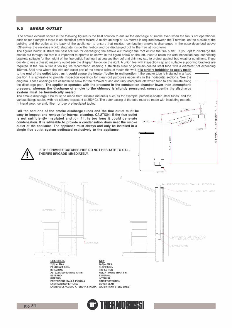
pg. 34
9.29 .29 .29 .29 .2 SMOKE OUTLETSMOKE OUTLETSMOKE OUTLETSMOKE OUTLETSMOKE OUTLET
•The smoke exhaust shown in the following figures is the best solution to ensure the discharge of smoke even when the fan is not operational,such as for example if there is an electrical power failure. A minimum drop of 1.5 metres is required between the T terminal on the outside of thebuilding and the outlet at the back of the appliance, to ensure that residual combustion smoke is discharged in the case described above(Otherwise the residues would stagnate inside the firebox and be discharged out to the free atmosphere).The figures below illustrate the best solution for discharging the smoke out through the roof or into the flue outlet. If you opt to discharge thesmoke out through the roof it is important to operate as shown in the figure below on the left. Insert a union tee with inspection cap, connectingbrackets suitable for the height of the flue outlet, flashing that crosses the roof and chimney cap to protect against bad weather conditions. If youdecide to use a classic masonry outlet see the diagram below on the right. A union tee with inspection cap and suitable supporting brackets arerequired. If the flue outlet is too big we recommend inserting a stainless steel or porcelain-coated steel tube with a diameter not exceeding150mm. Seal area where the inlet and outlet part of the smoke exhaust meets the wall. It is strictly forbidden to apply meshto the end of the outlet tube , as it could cause the heater / boiler to malfunction If the smoke tube is installed in a fixedposition it is advisable to provide inspection openings for clean-out purposes especially in the horizontal sections. See thediagram. These openings are essential to allow for the removal of ash and unburned products which tend to accumulate alongthe discharge path. The appliance operates with the pressure in the combustion chamber lower than atmosphericpressure, whereas the discharge of smoke to the chimney is slightly pressured, consequently the dischargesystem must be hermetically sealed.The smoke discharge tube must be made from suitable materials such as for example: porcelain-coated steel tubes, and thevarious fittings sealed with red silicone (resistant to 350°C). The outer casing of the tube must be made with insulating material(mineral wool, ceramic fiber) or use pre-insulated tubing.
All the sections of the smoke discharge tubes and the flue outlet must beeasy to inspect and remove for internal cleaning. CAUTION: if the flue outletis not sufficiently insulated and /or if it is too long it could generatecondensation. It is advisable to provide a condensation drain near the smokeoutlet of the appliance. The appliance must always and only be installed in asingle flue outlet system dedicated exclusively to the appliance.
IF THE CHIMNEY CATCHES FIRE DO NOT HESITATE TO CALLTHE FIRE BRIGADE IMMEDIATELY.
KEY2(-3) m MAXSLOPE 3-5%INSPECTIONHEIGHT MORE THAN 4 m.EXTERNALINTERNALRAIN PROTECTIONCOVER SLABWATERTIGHT STEEL SHEET
LEGENDA2(-3) m MAXPENDENZA 3-5%ISPEZIONEALTEZZA SUPERIORE A 4 m.ESTERNOINTERNOPROTEZIONE DALLA PIOGGIALASTRA DI COPERTURALAMIERA DI ACCIAIO A TENUTA STAGNA

pg. 35
PRESSOSTATO LATO FUMI
CIRCOLATORE
ASPIRATORE
RIARMO 100°CTERMOSTATO SICUR.
MOTORE PULIZIA
MOTORE CARICAMENTO
CIRCOLATORE
220-240V 50 Hz
1-4 Termostato Ambiente
1-6 Comando manuale retro3-5 Altoparlante
1-2 Cronotermostato
FLUSSOSTATO( OPTIONAL )
VALVOLADEVIATRICE( OPTIONAL )
62 41 53
6 4 25 3 1
BRUCIATORE
RESISTENZA
PELLETS
AGGIUNTIVO
FUMI
Fusibile 3,15
12
ON
Fusibile 3,15 A Fusibile 3,15
TERMOSTATO 42°C
PRESSOSTATOLATO ACQUA
TERMOCOPPIA
PER RADIOCOMANDO SELETTORE CODICI
MICROPROCESSORE
SCHEDINA TRASMETTITORE
RADIOCOMANDOSCHEDINA RICEVITORE
FLASH VOCISCHEDINA
2
Fusibile 1A
1 ON
9 VOCAL ALARMS9 VOCAL ALARMS9 VOCAL ALARMS9 VOCAL ALARMS9 VOCAL ALARMS
The heater / boiler is programmed to communicate 4 fundamental alarms. The vocal alarm is transmitted 4 times in rapid succession . It istransmitted in the following languages: Italian, English, German, French. These situations are repeated two more times a few minutes apart. If, however, the alarm is zeroed it will not be communicated.The alarms are :
Pellets finished + the same alarm in the other 3 languagesIncorrect start up + the same alarm in the other 3 languagesGeneral clean + the same alarm in the other 3 languagesBlocked smoke outlet + the same alarm in the other 3 languagesInsufficient water pressure + the same alarm in the other 3 languages
In detail:
Pellets finished : is communicated when the temperature during the RUNNING mode drops below 42 °C. This indicates that the appliance is switching off due to lack of pellets.
Incorrect start up : is communicated if after the start up phase the temperature does not rise above 42°C.
General clean : is indicated after the insert has operated for over 1800 hours.
Blocked smoke outlet : this occurs when the smoke outlet is partially blocked.
Insufficient water pressure : the pressure in the boiler has dropped below 0.3 bar. see para. 5.1.7),
To reset the alarm the fire must be out, disconnect the electric power supply, wait 2 seconds and power up the generator once again.
1010101010 ELECTRICAL WIRINGELECTRICAL WIRINGELECTRICAL WIRINGELECTRICAL WIRINGELECTRICAL WIRING
If another heater / boiler is installed in the vicinity of this heater then thecode selector in both the power board and the handheld radio control willhave to be reset; this is necessary to prevent interferences with theoperation of the two appliances. The code set in out products is standard.If you wish to alter the transmission code act on the selectors in the powerboard and the handheld radio control, making sure that they are setidentically.(see para. 5.1.12).A DATA ANALYSIS of all the variables as described in para. 5.1.6 must becarried out before the change can be activated.
PALMARE GESTITO VIA ONDE RADIOSELETTORE CODICI PER RADIOCOMANDO
ON
12
ON
1 2
KEYCode selector for handheld radio controlcontrolled by radio wavesFuseSmoke suction unitBurner cleaning motorReset thermostat 100°CPellet feed motorHeaterAdditional ricirculating pumpCirculating pumpDiverting valve (optional)Flow switch (optional)ThermocoupleRoom temperature thermostatChronothermostatRear manual controlLoudspeakerSmoke side pressure switchThermostat 42°CThermocoupleWater side pressure switchTransmitter boardRemote control receiver cardVoice flash cardMicroprocessorRadio control code selector
LEGENDASelettore codici per radiocomandopalmare gestito via onde radiofusibileaspiratore fumimotore pulizia bruciatoretermostato sicur. riarmo 100°Cmotore caricamento pellettsresistenzacircolatore aggiuntivocircolatorevalvola deviatrice (optional)flussostato (optional)termocoppiatermostato ambientecronotermostatocomando manuale retroaltoparlantepressostato lato fumitermostato 42°Ctermocoppiapressostato lato acquaschedina trasmettitoreschedina ricevitore telecomandoschedina flash vocimicroprocessoreselettore codici per radiocomando

pg. 36
1111111111 INFORMAINFORMAINFORMAINFORMAINFORMATION FOR TION FOR TION FOR TION FOR TION FOR THE SKILLED THE SKILLED THE SKILLED THE SKILLED THE SKILLED TECHNICIANTECHNICIANTECHNICIANTECHNICIANTECHNICIAN
11.1 Main components and their operation
SMOKE PRESSURE SWITCHThis is a safety switch that stops the screw feeder motor whenever necessary. The main cause for the pressure switch tripping is a blockedflue outlet or smoke exhaust pipe. Note that it is strictly forbidden to apply any kind of mesh screen to the end of the pipe. When the holes of themesh clog up they create a plug that trips the pressure switch which stops the pellet feeder.SCREW FEEDER MOTORThis motor is powered at regular on/off intervals controlled by a microprocessor. The operation of this motor is affected when:-The motor’s thermal cutout trips. -The pressure switch trips due to blocked smoke exhaust.-Pellets finished. -Intentional shut down of the heater / boiler.-Safety thermostat with manual reset trips.BURNER CLEANING MOTORThis device permits the creation inside the burner of a continual movement of combustion pellets and consequently an ongoing self-cleaning ofthe burner.SMOKE SUCTION UNITThis is activated when the start up signal is given. In the first two minutes it «washes» the smoke discharge tube, that is, it functions at maximumworking rate. Once this time has elapsed it self-adjusts to the optimal speed. The exhaust continues to operate for approximately one hour fromthe time the heater / boiler is switched off to allow for the evacuation of all the smoke and for safety purposes. It stops 30’ after the thermostatat 42°C opens.THERMOSTAT AT 42°CIts function is critical for the following reasons: When the contact closes the heater / boiler powers up and the working cycle starts. Similarly, when thecontact opens the smoke exhaust stops.EXPANSION TANK 2,5 lThis is a safety device intended to compensate for the increased volume of the water in the boiler caused by the increase in the watertemperature ( Note: this tank is a protection for the boiler only).SAFETY THERMOSTAT WITH MANUAL RESETWhen the temperature exceeds 98°C the pellet feed screw shuts down. A red light at the back of the appliance remains lit. Once the causes forthe overtemperature have been identified and remedied the appliance can be reactivated by unscrewing the plastic cover of the thermostatlocated at the back of the appliance and pressing the button (the heater / boiler temperature must be below 73 °C ).GLOW PLUGIt is activated in the START phase. Heats the air to 800°C, which assist the first combustion of the pellets present in the brazier.PRESSURE TRANSDUCERDetects the water pressure in the system. It is possible to verify the value by acting on the control panel as indicated in para. 5.2.AUTOMATIC PURGE VALVEThe function of this valve is to eliminate air residues inside the heater/boiler without the need for manual intervention. Consequently problemssuch as the following are eliminated:-corrosive processes caused by the oxygen. - noise generated by the passage of air in the tubes.-air pockets in the heating bodies. - cavitation in the circulator pumps .SAFETY VALVE CALIBRATED AT 3 BARWhen the calibrated pressure is reached, the valve opens and, by discharging to the atmosphere (the manufacturer recommends connecting thisvalve to a single outlet to avoid damaging the material surrounding the heater / boiler if it is activated ) it prevents the pressure in the system fromreaching dangerous limits for the generator and for the components of the system . If it trips verify the reasons and solve the causes for theoverpressure.SYSTEM CIRCULATOR PUMPThis device conveys hot water produced by the appliance to the usage point. The pump signal described in 5.1.1.2 appears to indicate that it isoperating.
11.2 USEFUL ADVICE FOR INSTALLATION AND OPERATION1 The appliance must never be deliberately disconnected from the electric power supply. Whenever the appliance is deliberately disconnected
from the electric power supply smoke could be emitted into the room and be a hazard. Similarly never switch off the appliance by suddenlycutting off the electric power supply.
2 Do not install the appliance with horizontal wall outlets only: evacuation of the combustion products must be guaranteed in a natural manner.3 Do not install the appliance with horizontal sections only: the wall could be exposed to high wind conditions and the appliance could shut
down due to back draft.4 Operate the appliance at maximum for 10 hours for a complete drying and baking of the silicates contained in the enamel which covers the
body of the heater.5 Do not install a grill or outlet terminal which could restrain the flow of the combustion gases: this could affect the dynamic gas to the point
where it would not allow the pellets to burn correctly.6 Read this instruction booklet.7 Keep the appliance clean and check the burner as described in this manual.8 Clean the smoke outlet regularly.9 Use top quality pellets: by saving 20 cents a bag you heat up to 50% less.10 Maximum useable lengths of smoke exhaust tubes: Painted aluminized steel tubes (1.5 mm minimum thickness), Aisi 316 stainless steel tubes or 0.5 mm enamelled tubes may be used. Minimum vertical length 4 m Maximum vertical length 8 m Length with min slope .5% 0.5 m Maximum number of elbows at least 0.5 m apart 2

pg. 37
11.3 TROUBLESHOOTING CAUSE-SOLUTION
PROBLEM CAUSE SOLUTION PELLET TANK IS EMPTY FILL UP THE TANK FOREIGN BODY SUCH AS NAIL, NYLON, PIECE OF WOOD ON THE FEEDER SCREW ON THE BOTTOM OF THE TANK
REMOVE THE FOREIGN BODY.
SMOKE EXHAUST NOT FREE, OR WITH TERMINAL THAT OBSTRUCTS THE PASSAGE OF SMOKE
CHECK THE SMOKE EXHAUST AS IT COULD BE DIRTY OR CLOGGED.
OUTLET TERMINAL CLOGGED BECAUSE A GRILL OR TERMINAL HAS BEEN INSERTED WHICH PREVENTS THE FREE PASSAGE OF SMOKE.
REMOVE THE TERMINAL AND REPLACE IT WITH A MORE SUITABLE ONE.
PELLETS DO NOT DROP INTO THE BURNER.
SUDDEN GUST OF WIND WHICH HAS MADE THE APPLIANCE GO INTO SAFETY MODE.
SWITCH THE POWER SUPPLY TO THE APPLIANCE OFF THEN BACK ON AGAIN.
SMOKE EXHAUST NOT FREE, OR WITH TERMINAL THAT OBSTRUCTS THE PASSAGE OF SMOKE
REMOVE THE TERMINAL AND REPLACE IT WITH A SUITABLE TERMINAL. CHECK THE SMOKE EXHAUST AS IT COULD BE DIRTY OR CLOGGED
BURNER IS DIRTY CLEAN THE BURNER ON A MORE FREQUENT BASIS
THE APPLIANCE ACCUMULATES PELLETS IN THE BRAZIER WHILE OPERATING.
PELLETS WITH DEPOSIT ABOVE PERMISSBILE LIMITS
CLEAN THE BURNER MORE OFTEN. SET OPERATING PROGRAM P2.
OCCURS THE FIRST TIME THE HEATER IS SWITCHED ON AS THE SILICONE PAINT IS BEING BAKED
RUN THE HEATER AT FULL POWER FOR 10 HOURS TO COMPLETE THE BAKING.
THE SMOKE EXHAUST IS NOT SEALED CORRECTLY
MAKE SURE THAT THE GASKETS HAVE BEEN FITTED TO THE SMOKE EXHAUST PIPES
IF THE APPLIANCE STARTS TO SMOKE AFTER 25 MINUTES: DIRTY BURNER, VERY DELAYED START
CLEAN THE BURNER
THE APPLIANCE SMOKES
IF THE APPLIANCE STARTS TO SMOKE AFTER 25 MINUTES: DELAYED START BECAUSE THE SCREW FEEDER IS EMPTY
FILL UP THE TANK
DELAYED START BECAUSE THE SCREW FEEDER IS EMPTY
FILL UP THE TANK THE APPLIANCE SHUTS OFF 5 MINUTES AFTER THE END OF THE START UP CYCLE
DIRTY BURNER, VERY DELAYED START CLEAN THE BURNER
THE APPLIANCE ACCUMULATES PELLETS IN THE BRAZIER
SEE POINT “ PROBLEM-CAUSE-SOLUTION” “ THE APPLIANCE ACCUMULATES PELLETS IN THE BRAZIER WHILE OPERATING”
NO CAUSE CLEAN THE GLASS MORE OFTEN
THE GLASS IS COVERED IN BLACK SOOT (H20)
BRAZIER BLADE (SEE PARA. 7.3) NOT PLACED CORRECTLY OR MISSING
PLACE THE BLADE CORRECTLY OR INSTALL IT
THE APPLIANCE IS OFF BUT THERE ARE UNBURNT PELLETS IN THE BRAZIER
THE TANK IS EMPTY EMPTY THE BURNER AND FILL UP THE TANK
THE APPLIANCE EXECUTES COMMANDS THAT HAVE NOT BEEN SET
THERE IS ANOTHER THERMOROSSI HEATER INSTALLED IN THE VICINITY OF THIS HEATER
CHANGE THE CODE SELECTOR
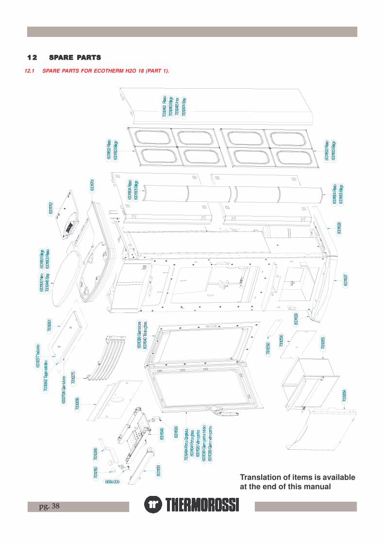
pg. 38
1212121212 SPSPSPSPSPARE PARE PARE PARE PARE PARARARARARTSTSTSTSTS
12.1 SPARE PARTS FOR ECOTHERM H2O 18 (PART 1).
70012
462
Rosso
70012
463 B
eige
70012
465 I
nox
70012
474 E
asy
60011
802 R
osso
60011
803 B
eige
60011
805 B
eige
60011
804 R
osso
60011
805 B
eige
60011
804 R
osso
60011
803 B
eige
60011
802 R
osso
80011
638
80011
637
80011
639
70012
448 E
asy60
011812
Nero
60011
800 R
osso
60011
801 B
eige
60011
762
60011
761
70012
275
70012
484 P
orta C
omple
ta80
01164
1 Port
a ghis
a60
01152
6 Vetr
o port
a60
01034
1 Gua
rn. po
rta-te
laio
60010
336 Gu
arn. ve
tro po
rta
80011
640 T
elaio
ghisa
60010
336 Gu
arnizi
one
70012
658
80011
649
60011
699
60011699
80011
651
70012
15070
01228
6
70012
592 70012
596
70012
655
70012
654
70012
661
60012
577 I
solan
te
70012
662 T
appo
salda
to
6000
7534
Guarn
izione
Translation of items is availableat the end of this manual

pg. 39
12.2 SPA
RE
PAR
TS FO
R E
CO
THE
RM
H2O
18 (PAR
T 2).
70012603 Radiocomando Aladino
60011787 Batteria ricaricabile
60011788 Caricabatteria Batteria
60011786 Supporto a muro
60011783 Coperchio pila ricaricabile
60010185
70010402
60011645
60004241
70010234
60012571
60011707
70012677
6000746260011656
60012586 60012600
60012599
60011795
60006682
60012593
60012594
60012591
60012590
60012595
60005254 Piedino
60011693
60012598
60012644 Valvola deviatrice
60012641 Rivelatore Hall
60010343
60011246
60011643
60011643
60011644
60010185
6001164460010185
60010185
70010234
70012772
60012654 Solo ventilatore
60011630 Condensatore
60011678
60010190
60004921
60012583
70012676
60012661 Schedina flash voci
60012662 Scheda ricevitore
60012663 Scheda trasmettitore
70012665
70012668
70012669
60011671
60012588
60012659 Microchip H2O

pg. 40
12.3 SPARE PARTS FOR ECOTHERM COMPACT 18 (PART 1).
6001
1282
6001
1282
6001
1732
7001
2215
8001
1649
8001
1651
6001
1699
6001
1699
7001
2150
7001
2286
6001
1282
6001
1282
6001
1732
7001
2718
7001
2661
7001
2662
Tapp
o sa
ldat
o
6001
2577
Isola
nte
7001
2721
7001
2658
7001
2596
7001259270
0126
55
7001
2654
7001
2719
7001
2717
7001
2723
6001
2609
7001
2702
7001
2213
6001
1731
7001
2705
Porta
Sal
data
6001
2606
Isola
zione
6000
7534
Gua
rnizi
one
6000
7534
Gua
rnizi
one
Translation of items is availableat the end of this manual
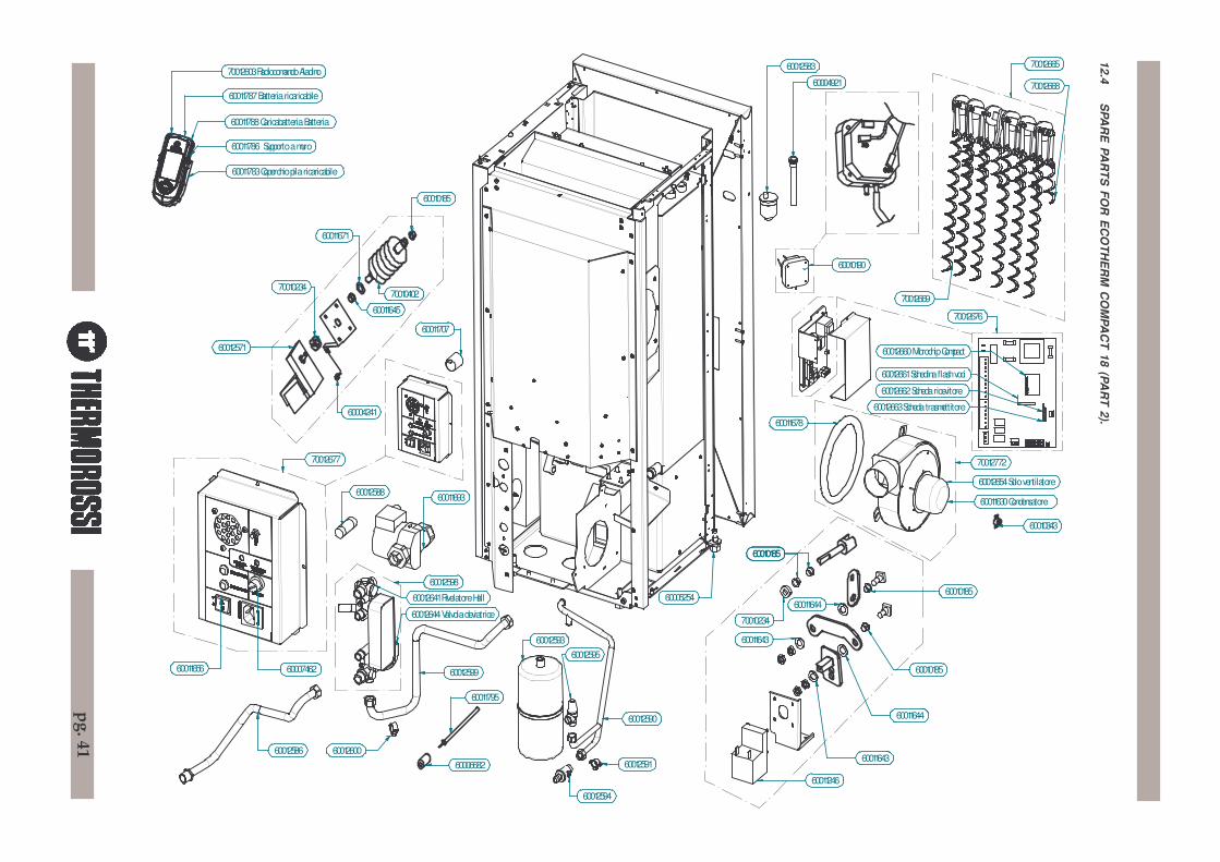
pg. 41
12.4 SPA
RE
PAR
TS FO
R E
CO
THE
RM
CO
MPA
CT 18 (PA
RT 2).
70012603 Radiocomando Aladino
60011787 Batteria ricaricabile
60011788 Caricabatteria Batteria
60011786 Supporto a muro
60011783 Coperchio pila ricaricabile
60010185
70010402
60011645
60004241
70010234
60012571
60011707
70012677
6000746260011656
60012586 60012600
60012599
60011795
60006682
60012593
60012594
60012591
60012590
60012595
60005254
60011693
60012598
60012644 Valvola deviatrice
60012641 Rivelatore Hall
60010343
60011246
60011643
60011643
60011644
60010185
6001164460010185
6001018560010185
70010234
70012772
60012654 Solo ventilatore
60011630 Condensatore
60011678
60010190
60004921
60012583
70012676
60012660 Microchip Compact
60012661 Schedina flash voci
60012662 Scheda ricevitore
60012663 Scheda trasmettitore
70012665
70012668
70012669
60011671
60012588