The European Spallation Source - CERNaccelconf.web.cern.ch/AccelConf/IPAC2011/papers/fryba01.pdf ·...
5
THE EUROPEAN SPALLATION SOURCE S. Peggs ∗ , ESS, Lund, Sweden for ESS/AD and the ESS/ADU Collaboration Abstract Lund was chosen as the site for the European Spallation Source (ESS) in 2009, and a company, ESS AB, was cre- ated to design, build and operate it. In 2010 the Accelerator Design Update (ADU) collaboration was formed to update the design that was the established in 2003, and to deliver a Technical Design Report at the end of 2012 [1]. Detailed planning for the Prepare-to-Build prototyping project has begun, and potential future power upgrades are being con- sidered. First protons are expected in 2018, and first neu- trons in 2019 [2]. The updated design delivers 5 MW of 2.5 GeV protons to a single target, in 2.86 ms long pulses with a 14 Hz repeti- tion rate. The linac will have a normal conducting front end with an ion source, a Radio Frequency Quadrupole (RFQ), and a Drift Tube Linac (DTL). The superconducting sec- tion of the linac contains spoke cavities followed by two families of elliptical cavities [3]. The ESS has the ambi- tious goal of being a sustainable research facility with zero release of carbon dioxide [4]. This will be achieved through a combination of actions, with a focus on the linac – the most energy hungry component. Care is being taken to op- timize the overall energy efficiency, and to re-use the hot water coming out of the facility. INTRODUCTION Spallation is the nuclear process that emits neutrons at a spectrum of energies after highly energetic particles bom- bard heavy nuclei – for example, when the ESS proton beam strikes a rotating tungsten disk target. These neutrons are cooled in moderators adjacent to the target, before be- ing transported of order 100 m through neutron guides to experimental instruments [5]. The neutron time-of-flight, and therefore individual neu- tron energies, are readily measured at pulsed sources like the Spallation Neutron Source (SNS) and the ESS. The SNS combines a full energy superconducting linac with an accumulator/compressor ring to provide high intensity short pulses (∼1 μs) of protons to a mercury target. The ESS avoids the need for a costly and performance-limiting ring, by delivering even higher intensities to experiments that are capable of using long pulses (∼3 ms) [6]. Long pulse implementations also permit H + operation, main- taining relatively low peak currents, and enabling small emittances and apertures in all beamlines. It is generally agreed that a kinetic energy of 1–3 GeV is optimal for practical target and moderator designs, and in order to keep the shielding requirements reasonable. The ∗ [email protected] ESS energy of 2.5 GeV enables an average macro-pulse current of 50 mA that is consistent with the need for high reliability, but still leaves some leeway for a potential en- ergy (and thus power) upgrade. The current limit is mainly set by space charge effects at low energy, by the power that can be delivered to the beam in each cavity at medium and high energies, and by beam losses. Table 1: High level ESS parameters. Parameter Unit Value Average beam power on target MW 5.0 Proton kinetic energy on target GeV 2.5 Average macro-pulse current mA 50 Macro-pulse length ms 2.86 Pulse repetition rate Hz 14 Number of instruments 22 Number of target ports 50 Reliability % 95 Maximum average beam loss rate W/m 1.0 RF frequency: RFQ, DTL, spokes MHz 352.21 RF frequency: elliptical cavities MHz 704.42 LAYOUT The accelerator achieves the high level parameters listed in Table 1 using the schematic “2011 hybrid” baseline lay- out shown in Figure 1, in which the linac is optimized for 50 mA operation with a single cavity per klystron [7, 8]. High level parameters (such as the 5 MW beam power) are rigidly fixed, while some lower level parameters are subject to modest evolution. Live parameters, continuously main- tained and under configuration change control, are publicly available on-line [9, 10]. Layout changes in the last year were influenced by factors like the geometry of the cry- omodules, the maximum gradient in the cavities, and the choice of phase advance in the superconducting linac. Lat- tice parameters exist in piecemeal form, from the partners in the ADU collaboration. Complete integration into a sin- gle end-to-end lattice is scheduled for the autumn of 2011. Proton source. There is no need for charge exchange injection (into an accumulator ring) for a long pulse source, so the ESS ion source will produce a proton beam. The source will be a compact Electron Cyclotron Resonance source similar to the VIS source [11] in Catania, and the SILHI source [12] at CEA-Saclay. LEBT and RFQ. Beam is transported from the ion source through the LEBT to the RFQ, for bunching and Proceedings of IPAC2011, San Sebastián, Spain FRYBA01 04 Hadron Accelerators A15 High Intensity Accelerators 3789 Copyright c ○ 2011 by IPAC’11/EPS-AG — cc Creative Commons Attribution 3.0 (CC BY 3.0)
Transcript of The European Spallation Source - CERNaccelconf.web.cern.ch/AccelConf/IPAC2011/papers/fryba01.pdf ·...

THE EUROPEAN SPALLATION SOURCE
S. Peggs∗, ESS, Lund, Swedenfor ESS/AD and the ESS/ADU Collaboration
Abstract
Lund was chosen as the site for the European SpallationSource (ESS) in 2009, and a company, ESS AB, was cre-ated to design, build and operate it. In 2010 the AcceleratorDesign Update (ADU) collaboration was formed to updatethe design that was the established in 2003, and to delivera Technical Design Report at the end of 2012 [1]. Detailedplanning for the Prepare-to-Build prototyping project hasbegun, and potential future power upgrades are being con-sidered. First protons are expected in 2018, and first neu-trons in 2019 [2].
The updated design delivers 5 MW of 2.5 GeV protons toa single target, in 2.86 ms long pulses with a 14 Hz repeti-tion rate. The linac will have a normal conducting front endwith an ion source, a Radio Frequency Quadrupole (RFQ),and a Drift Tube Linac (DTL). The superconducting sec-tion of the linac contains spoke cavities followed by twofamilies of elliptical cavities [3]. The ESS has the ambi-tious goal of being a sustainable research facility with zerorelease of carbon dioxide [4]. This will be achieved througha combination of actions, with a focus on the linac – themost energy hungry component. Care is being taken to op-timize the overall energy efficiency, and to re-use the hotwater coming out of the facility.
INTRODUCTION
Spallation is the nuclear process that emits neutrons at aspectrum of energies after highly energetic particles bom-bard heavy nuclei – for example, when the ESS protonbeam strikes a rotating tungsten disk target. These neutronsare cooled in moderators adjacent to the target, before be-ing transported of order 100 m through neutron guides toexperimental instruments [5].
The neutron time-of-flight, and therefore individual neu-tron energies, are readily measured at pulsed sources likethe Spallation Neutron Source (SNS) and the ESS. TheSNS combines a full energy superconducting linac withan accumulator/compressor ring to provide high intensityshort pulses (∼1 μs) of protons to a mercury target. TheESS avoids the need for a costly and performance-limitingring, by delivering even higher intensities to experimentsthat are capable of using long pulses (∼3 ms) [6]. Longpulse implementations also permit H+ operation, main-taining relatively low peak currents, and enabling smallemittances and apertures in all beamlines.
It is generally agreed that a kinetic energy of 1–3 GeV isoptimal for practical target and moderator designs, and inorder to keep the shielding requirements reasonable. The
ESS energy of 2.5 GeV enables an average macro-pulsecurrent of 50 mA that is consistent with the need for highreliability, but still leaves some leeway for a potential en-ergy (and thus power) upgrade. The current limit is mainlyset by space charge effects at low energy, by the power thatcan be delivered to the beam in each cavity at medium andhigh energies, and by beam losses.
Table 1: High level ESS parameters.
Parameter Unit Value
Average beam power on target MW 5.0Proton kinetic energy on target GeV 2.5Average macro-pulse current mA 50Macro-pulse length ms 2.86Pulse repetition rate Hz 14Number of instruments 22Number of target ports 50Reliability % 95Maximum average beam loss rate W/m 1.0RF frequency: RFQ, DTL, spokes MHz 352.21RF frequency: elliptical cavities MHz 704.42
LAYOUT
The accelerator achieves the high level parameters listedin Table 1 using the schematic “2011 hybrid” baseline lay-out shown in Figure 1, in which the linac is optimized for50 mA operation with a single cavity per klystron [7, 8].High level parameters (such as the 5 MW beam power) arerigidly fixed, while some lower level parameters are subjectto modest evolution. Live parameters, continuously main-tained and under configuration change control, are publiclyavailable on-line [9, 10]. Layout changes in the last yearwere influenced by factors like the geometry of the cry-omodules, the maximum gradient in the cavities, and thechoice of phase advance in the superconducting linac. Lat-tice parameters exist in piecemeal form, from the partnersin the ADU collaboration. Complete integration into a sin-gle end-to-end lattice is scheduled for the autumn of 2011.
Proton source. There is no need for charge exchangeinjection (into an accumulator ring) for a long pulse source,so the ESS ion source will produce a proton beam. Thesource will be a compact Electron Cyclotron Resonancesource similar to the VIS source [11] in Catania, and theSILHI source [12] at CEA-Saclay.
LEBT and RFQ. Beam is transported from the ionsource through the LEBT to the RFQ, for bunching and
Proceedings of IPAC2011, San Sebastián, Spain FRYBA01
04 Hadron Accelerators
A15 High Intensity Accelerators 3789 Cop
yrig
htc ○
2011
byIP
AC
’11/
EPS
-AG
—cc
Cre
ativ
eC
omm
onsA
ttri
butio
n3.
0(C
CB
Y3.
0)
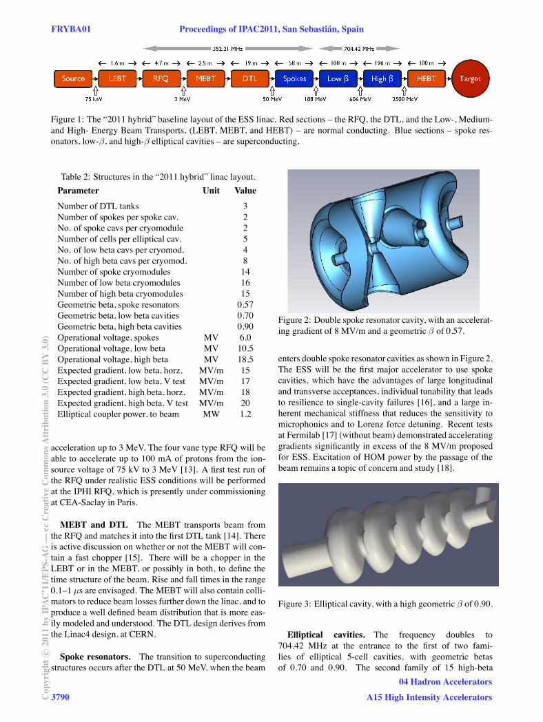
Figure 1: The “2011 hybrid” baseline layout of the ESS linac. Red sections – the RFQ, the DTL, and the Low-, Medium-and High- Energy Beam Transports, (LEBT, MEBT, and HEBT) – are normal conducting. Blue sections – spoke res-onators, low-β, and high-β elliptical cavities – are superconducting.
Table 2: Structures in the “2011 hybrid” linac layout.
Parameter Unit Value
Number of DTL tanks 3Number of spokes per spoke cav. 2No. of spoke cavs per cryomodule 2Number of cells per elliptical cav. 5No. of low beta cavs per cryomod. 4No. of high beta cavs per cryomod. 8Number of spoke cryomodules 14Number of low beta cryomodules 16Number of high beta cryomodules 15Geometric beta, spoke resonators 0.57Geometric beta, low beta cavities 0.70Geometric beta, high beta cavities 0.90Operational voltage, spokes MV 6.0Operational voltage, low beta MV 10.5Operational voltage, high beta MV 18.5Expected gradient, low beta, horz. MV/m 15Expected gradient, low beta, V test MV/m 17Expected gradient, high beta, horz, MV/m 18Expected gradient, high beta, V test MV/m 20Elliptical coupler power, to beam MW 1.2
acceleration up to 3 MeV. The four vane type RFQ will beable to accelerate up to 100 mA of protons from the ion-source voltage of 75 kV to 3 MeV [13]. A first test run ofthe RFQ under realistic ESS conditions will be performedat the IPHI RFQ, which is presently under commissioningat CEA-Saclay in Paris.
MEBT and DTL The MEBT transports beam fromthe RFQ and matches it into the first DTL tank [14]. Thereis active discussion on whether or not the MEBT will con-tain a fast chopper [15]. There will be a chopper in theLEBT or in the MEBT, or possibly in both, to define thetime structure of the beam. Rise and fall times in the range0.1–1 μs are envisaged. The MEBT will also contain colli-mators to reduce beam losses further down the linac, and toproduce a well defined beam distribution that is more eas-ily modeled and understood. The DTL design derives fromthe Linac4 design, at CERN.
Spoke resonators. The transition to superconductingstructures occurs after the DTL at 50 MeV, when the beam
Figure 2: Double spoke resonator cavity, with an accelerat-ing gradient of 8 MV/m and a geometric β of 0.57.
enters double spoke resonator cavities as shown in Figure 2.The ESS will be the first major accelerator to use spokecavities, which have the advantages of large longitudinaland transverse acceptances, individual tunability that leadsto resilience to single-cavity failures [16], and a large in-herent mechanical stiffness that reduces the sensitivity tomicrophonics and to Lorenz force detuning. Recent testsat Fermilab [17] (without beam) demonstrated acceleratinggradients significantly in excess of the 8 MV/m proposedfor ESS. Excitation of HOM power by the passage of thebeam remains a topic of concern and study [18].
Figure 3: Elliptical cavity, with a high geometric β of 0.90.
Elliptical cavities. The frequency doubles to704.42 MHz at the entrance to the first of two fami-lies of elliptical 5-cell cavities, with geometric betasof 0.70 and 0.90. The second family of 15 high-beta
FRYBA01 Proceedings of IPAC2011, San Sebastián, Spain
3790Cop
yrig
htc ○
2011
byIP
AC
’11/
EPS
-AG
—cc
Cre
ativ
eC
omm
onsA
ttri
butio
n3.
0(C
CB
Y3.
0)
04 Hadron Accelerators
A15 High Intensity Accelerators

Figure 4: Interface between the HEBT, the rotating tung-sten disk target, moderators, and the 22 neutron beamlines.
cryomodules, each with 8 cavities, delivers about 75%of the total proton energy, from 600 MeV to 2.5 GeV.The cavity geometry shown in Figure 3 includes only thefundamental power coupler. The option of adding a HOMcoupler to extract HOM power is under active discussion.
HEBT, target and neutron beamlines. Figure 4shows the HEBT rising vertically 10 m (with no horizontalbend) out of a FODO channel into a target that sits 1.6 mabove ground level. The uphill straight is available for mo-mentum and betatron collimation. The solid rotating tung-sten target is cooled by helium gas. Specifications of thesize and intensity distribution of the beam on the targetare under discussion. The power dissipation and distribu-tion on the proton-beam window (separating the linac vac-uum from the target atmosphere) are also under study. Notshown in Figure 4 is the straight-ahead tune-up dump thatreceives beam when the vertical dipoles are turned off. Thedesign of the beam flattening and the HEBT as a whole isbeing elaborated by the Arhus group [19, 20, 21].
HYBRID CRYOMODULES
Superconducting linacs typically have continuous (egXFEL) or segmented (eg SNS) cryostats. A continuouscryostat has a lower static heat load on the cryogenic plant,reducing energy consumption and operational costs. Eachsegmented cryomodule has its own insulation vacuum, andrequires jumper connections to an external cryogenic distri-bution line. A segmented design is more serviceable, sinceindividual cryomodules can be valved off, warmed, and re-paired or exchanged. Further, beam instrumentation can beplaced in the warm spaces between segmented cryomod-ules. Beam instrumentation is in general more challengingfor a H+ linac than for an H− linac. For instance, it wouldrequire a significant R&D effort to develop a beam-profilemonitor that operates efficiently at 2 K [22, 23, 24].
The current ESS baseline adopts a hybrid design, inwhich a cold interconnect between neighboring cryomod-ules is enclosed by a sleeve that is cooled to the interme-diate temperature of the outer thermal screen of the maincryostats, about 70 K. This reduces the heat load and per-mits some of the interconnects to be left at room tempera-
2K 2K 2K 2K 2K 2K2K 2K
70K70K
BI BI
300K
Figure 5: Interconnects between hybrid cryomodules maybe either warm or cold (∼ 70 K).
ture, as shown in Figure 5. This hybrid scheme is mechan-ically more complex than a simple segmented design. Itsrelative advantages and disadvantages are under evaluation.
BEAM PHYSICS
Optics. Figure 6 (top) shows transverse beta functionsthat increase along the length of the linac, driven by dou-blet quadrupoles that weaken as the proton energy in-creases. The transverse RMS beam size remains approxi-mately constant, with very little emittance growth. Figure 6(bottom) represents the longitudinal optics by the phase ad-vance per cryomodule, driven by the longitudinal cavitystrengths recorded (indirectly) in Figure 7.
Figure 7 records the RF power sources requirementsfor a smooth acceleration transition between the differentfamilies of superconducting structures. The linac will bepowered by one klystron per superconducitng cavity, plusone for the RFQ, and (1,2,2) for DTL tanks (1,2,3). Thisgives maximum flexibility for beam tuning and robustnessagainst faults – the linac can be retuned to operate afterthe failure of any individual SC cavity [16]. The powersources are gradient-limited rather than power-limited at50 mA beam current [25], but with only a modest margin.
Figure 6: Transverse beta functions (top) and the longitu-dinal phase advance per cryomodule (bottom), for most ofthe ESS linac.
Proceedings of IPAC2011, San Sebastián, Spain FRYBA01
04 Hadron Accelerators
A15 High Intensity Accelerators 3791 Cop
yrig
htc ○
2011
byIP
AC
’11/
EPS
-AG
—cc
Cre
ativ
eC
omm
onsA
ttri
butio
n3.
0(C
CB
Y3.
0)

Figure 7: The power to beam of the superconducting partof the linac [26], as calculated from the lattice in [27].
Simulations and beam losses. Beam-dynamics simu-lations show that the transverse acceptance of the super-conducting linac is an order of magnitude larger than theRMS emittance of the beam in an ideal linac, and also sub-stantially larger than the envelope given by the outermostparticles [28, 29]. Longitudinally, the acceptance is twoorders of magnitude larger than the RMS emittance.
Excessive radio-activation from beam losses larger thanabout 1 W/m would hinder hands-on maintenance. Beamlosses from aperture limitations, transition regions and mis-alignment are readily simulated, yielding mechanical tol-erances for cavity designs, supporting infrastructure andother equipment. Intra-beam stripping is plausibly an im-portant source of beam losses in H− linacs like the SNS,but not in the H+ ESS [30]. Other beam loss sources areHoffman space charge resonances [31], transverse over-focusing [32], and uncollimated low energy beam halo. At-taining the ability to confidently predict the relative impor-tance of loss mechanisms is a fundamental challenge to ourability to design multi-MW proton linacs.
RADIO FREQUENCY SYSTEMS
RF frequency. Lower frequencies are favored at lowerenergies due to relaxed manufacturing tolerances in cav-ity components, and to the capacity for large beam aper-tures. They also increase the transverse focusing strengthof RFQs, reduce RF losses in cavities, and mitigate HOMeffects. Higher frequencies decrease the cavity size, mak-ing them easier to handle and reducing manufacturingcosts, and also reduce the cryogenic envelope and powerconsumption with superconducting structures. A frequencyof 600–800 MHz is a good compromise for elliptical struc-tures like the CERN Superconducting Proton Linac andthe ESS, which both share frequencies of 352.21 MHz and704.42 MHz, at low and high energies [33, 34].
RF power distribution. Special care has to be takenwith the design of the RF power sources, distribution sys-tem and controls [35], due to severe space limitations, reli-ability and safety concerns and high investment and opera-
tional costs [36]. The ESS design goal of being a sustain-able research facility requires the minimization of powerconsumption, and the re-use of all heat from cooling water.The entire facility is divided into different categories, de-pending on the cooling needs and the temperature rangefor reliable equipment operation. The highest tempera-ture zones will be the RF loads, circulators, compressors,and the klystrons collectors, according to SNS experience.Higher temperature operation of these systems permits thetemperature of the cooling water leaving the facility to avalue (> 70 C) that enables re-sale to the district heatingsystem of the local community.
Higher Order Modes. High energy efficiency re-quires superconducting RF structures with very high qual-ity factors. Consequently, each HOM tends to have a longdamping time, with a significant risk that it will still beactive when the next macro-pulse arrives. It has beenshown [37] that HOMs may harm high power proton beamquality, primarily if HOMs are strongly coupled with thefrequency content of the beam. HOM excitation and decaymust be very well understood and, if necessary, suppressed,in order to avoid disrupting longitudinal phase space, per-haps causing beam loss beyond the 1 W/m limit [38]. Ifnecessary, the ESS will remove HOM power using couplersplaced at cavity locations where the more destructive par-asitic modes have large amplitudes, rather than lossy ma-terial around the beam pipe between neighboring cavities.HOM couplers can also be instrumented to measure the 4Dtransverse location of the beam [39]. Ongoing beam dy-namics studies will form an important part of the decisionon whether or not to install HOM couplers [40].
Field Emission & MultiPacting. SNS experience in-dicates that FE & MP could significantly limit the perfor-mance of the ESS elliptical cavities [41]. FE electrons loston the cavity walls increase the load on the cryogenic sys-tem, and decrease the quality factor of the cavity. FE elec-trons may also thermal detune the notch filter used to rejectthe accelerating mode from the HOM coupler (if present),causing excessive power to be coupled out into the HOMelectronics. Further, excessive MP could quench cavities,and could disrupt longitudinal phase space. The FE/MPphenomena that cause problems at SNS are particularlycomplex. Several different simulation–based calculationshave commenced, on individual couplers, full cavities, andmultiple cavities [42].
Low Level RF. RF stability is particularly importantin proton linacs, because the semi-relativistic velocitiescause phase and amplitude errors in one cavity to alterbeam arrival times in downstream cavities. These errorsaccumulate along the length of the linac. Investigationsof phase and amplitude errors due to modulator ripple anddroop have begun [43, 44]. Proportional and proportional–integral (PI) controllers are being studied for the normal–conducting and superconducting cavities.
FRYBA01 Proceedings of IPAC2011, San Sebastián, Spain
3792Cop
yrig
htc ○
2011
byIP
AC
’11/
EPS
-AG
—cc
Cre
ativ
eC
omm
onsA
ttri
butio
n3.
0(C
CB
Y3.
0)
04 Hadron Accelerators
A15 High Intensity Accelerators

POTENTIAL UPGRADES
Different upgrade strategies available to the ESS are un-der discussion, within the constraint of a single target sta-tion [45]. Short pulse operation with H− beam is not underconsideration. In general, the ESS baseline design is opti-mized for 5 MW, but may incorporate features providingupgrade potential, so long as their day-one inclusion is in-expensive. Thus, the target monolith is equipped with 50neutron beam ports, providing a potential path towards atotal of 44 experimental instruments. Similarly, provisionmay be made for parasitic proton extraction lines, and alsofor a power upgrade.
Superficially, a power upgrade to 7.5 MW “just” requiresraising the average beam current to 75 mA. However, theESS design, optimized for50 mA, could be difficult or in-efficient to operate at higher currents, for example due tomismatching between the RF coupler and the beam loadedcavity, and due to HOM effects. Upgrades to larger beamcurrents would require upgraded RF power sources, or re-duced accelerating voltages. Increasing the current of theproton beam would also require redesigning the front end,including the ion source.
The beam power could also be increased by raising theproton beam energy, or the repetition rate. The 14 Hz rep-etition rate is intimately linked to instrument design andlocation, and is very difficult to change. Either an energyupgrade or a current upgrade – or a judicious mixture of thetwo – would require additional acceleration cavities unlessthe RF power sources are changed.
Any power upgrade would also require the target, itscooling, and shielding to be redesigned. An energy up-grade must also take into account the higher energy targetconditions. For example, the centre of neutron productionwould move a few centimetres if the energy increased from2.5 GeV to 3.0 Gev. However, a pure energy upgrade us-ing additional accelerating structures would have little in-fluence on beam dynamics and would not require any majormodification of the existing linac.
CONCLUSION
The on-going Accelerator Design Update project willresult in a Technical Design Report with associated cost-ing and scheduling at the end 2012. It will also produceinterface and requirement documents for the next project,“Prepare-to-Build” (P2B), which will deliver all manufac-turing specifications and detailed integration plans in atimely fashion. P2B will also permit orders to be placed,and allow testing and construction and assembly to begin,so that protons can be delivered to the target station in 2018.These projects are being performed in a collaboration be-tween European universities and institutes with importantcontributions from overseas laboratories and universities.
REFERENCES
[1] C.Oyon, these proceedings, WEIB05.
[2] T.Hansson et al, these proceedings, WEPC166.
[3] G.Devanz, these proceedings, TUZB01.
[4] C.Carlile, these proceedings, THEA01.
[5] B.Willis & C.J.Carlile, Oxford University Press, ISBN 978-0-19-851970-6, 2009.
[6] F.Mezei, J. Neutron Research 6 3-32, 1997.
[7] H.Danared, these proceedings, WEPS059.
[8] M.Eshraqi, these proceedings, WEPS060.
[9] http://esss.se/linac/Parameters.html
[10] K.Rathsman et al, these proceedings, TUPS096.
[11] S. Gammino et al, ECRIS10, MOPOT012, 2010.
[12] R.Gobin et al, Rev.Sci.Instr 73, 2002.
[13] R.Ainsworth et al, these proceedings, MOPC049.
[14] I.Bustinduy & J.L.Munoz, these proceedings, WEPC022.
[15] C.Plostinar et al, “Chopping options for ESS”, unpublished,2011.
[16] M.Eshraqi, these proceedings, WEPS063.
[17] R.Madrak et al, LINAC10, THP031, 2010.
[18] M. Lindroos, ESS AD Tech Note ESS/AD/0010, 2010.
[19] H.Danared, ESS AD Tech. Note ESS/AD/0008, 2011.
[20] A.Holm et al, these proceedings, THPS050.
[21] H.Thomsen et al, these proceedings, THPS031.
[22] A.Jansson & L.Tchelidze, DIPAC11, MOP184, 2011.
[23] A.Jansson et al, PAC11, TUPD02, 2011.
[24] L.Tchelidze & A.Jansson, these proceedings, TUPC131.
[25] M.Eshraqi et al, these proceedings, WEPS062.
[26] K. Rathsman et al, ESS AD Tech Note ESS/AD/0020, 2011.
[27] M. Eshraqi, ESS AD Tech Note ESS/AD/0007, 2011
[28] A.Ponton, these proceedings, MOPS039.
[29] M.Eshraqi & H.Danared, these proceedings, WEPS061.
[30] V. Lebedev et al, LINAC10, THP080, 2010.
[31] I.Hofmann & K.Beckert, IEEE TNS. NS-32, 2264, 1985.
[32] Y.Zhang et al, PRST-AB 11, 104001, 2008.
[33] F.Gerigk et al, CERN-AB-2008-064, 2008.
[34] M.Harrison et al, “ESS Frequency Advisory Board Report”,2010.
[35] I.Verstovsek et al, these proceedings, THXA01.
[36] K.Rathsman et al, these proceedings, MOPC136.
[37] M.Schuh et al, PRST-AB 14, 051001, 2011.
[38] C.Welsch et al, these proceedings, MOPS082.
[39] S.Molloy et al, PRST-AB 9, 112802, 2006.
[40] S.Molloy et al, these proceedings, MOODB02.
[41] I.Campisi et al, PAC07, WEPMS076, 2007.
[42] S.Molloy et al, these proceedings, MOPC050.
[43] R.Zeng et al, ESS AD Tech Note ESS/AD/0011, 2011.
[44] A.J.Johansson & R.Zeng, these proceedings, MOPC161.
[45] M.Lindroos et al, these proceedings, WEPS064.
Proceedings of IPAC2011, San Sebastián, Spain FRYBA01
04 Hadron Accelerators
A15 High Intensity Accelerators 3793 Cop
yrig
htc ○
2011
byIP
AC
’11/
EPS
-AG
—cc
Cre
ativ
eC
omm
onsA
ttri
butio
n3.
0(C
CB
Y3.
0)