The Equipment List on the following pages lists the major
28
JEA Large-Scale CFB Demonstration Project Detailed Public Design Report Appendix 4, p-1 APPENDIX 4 MAJOR EQUIPMENT LIST The Equipment List on the following pages lists the major equipment associated with the Repowering Project and is listed by the JEA GEMS (or System) Code. Since the P&ID’s are defined and numbered by their associated GEMS code, the equipment is also listed by P&ID. The quantity, percent capacity, and redundancy is indicated for each item of equipment. This information is indicated for Unit 2, Common, and Unit 1 equipment, since some items of equipment serve as an installed back-up for both units. A copy of the JEA GEMS Code Definitions is attached for reference.
Transcript of The Equipment List on the following pages lists the major

JEA Large-Scale CFB Demonstration Project
Detailed Public Design Report Appendix 4, p-1
APPENDIX 4
MAJOR EQUIPMENT LIST The Equipment List on the following pages lists the major equipment associated with the Repowering Project and is listed by the JEA GEMS (or System) Code. Since the P&ID’s are defined and numbered by their associated GEMS code, the equipment is also listed by P&ID. The quantity, percent capacity, and redundancy is indicated for each item of equipment. This information is indicated for Unit 2, Common, and Unit 1 equipment, since some items of equipment serve as an installed back-up for both units. A copy of the JEA GEMS Code Definitions is attached for reference.

JEA Large-Scale CFB Demonstration Project
Detailed Public Design Report Appendix 4, p-2
JEA Large-Scale CFB Demonstration Project
Major Equipment List
GEMS DESCRIPTION QUANTITY CAPACITY REMARKS SYSTEM UNIT 2 COMMON UNIT 1
AB INSTRUMENT AIR DRYERS 3 Nominal 50% Capacity Each Serve Units 1, 2, and 3
AC AIR COMPRESSORS 6 Nominal 25% Capacity Each Provide Service and Instrument Air for Units 1, 2, and 3
BB STEAM GENERATOR 1 1
BB STEAM DRUM 1 1
BC SECONDARY AIR TUBULAR AIR HEATER
1 1
BC PRIMARY AIR TUBULAR AIR HEATER 1 1
BF ELBOW DUCT BURNERS 3 3 For Start-up Only
BI SOOTBLOWER PRIMARYSUPERHEATER
8 8
BI SOOTBLOWER FINAL REHEATER 6 6
BI SOOTBLOWER REHEATER 6 6
BI SOOTBLOWER ECONOMIZER 16 16
BK BOILER BLOWDOWN DRUM 1 1
BN PRIMARY AIR FAN 2 2 50% Capacity Each
BN SECONDARY AIR FAN 2 2 50% Capacity Each

JEA Large-Scale CFB Demonstration Project
Detailed Public Design Report Appendix 4, p-3
GEMS DESCRIPTION QUANTITY CAPACITY REMARKS SYSTEM UNIT 2 COMMON UNIT 1
BN PRIMARY AIR BOOSTER BLOWER 3 3 For Duct Burners - Start-up Only
BN PRIMARY AIR FAN LUBE OIL SKID 2 2 One per Fan
BO INDUCED DRAFT FAN 2 2 50% Capacity Each
BO ID FAN INLET ISOLATION DAMPER 2 2 One per Fan
BO ID FAN OUTLET ISOLATION DAMPER 2 2 One per Fan
BO CONCRETE CHIMNEY 1 With Separate Flue for Each Unit
EF MCC/LOAD CENTER/SWITCHGEAR 1 LOT 1 LOT 1 LOT Essentially all MCC's, Load Centers, and Switchgear were replaced for Unit 2, Common, and Unit 1 Equipment
FG FUEL UNLOADING DOCK 1
FH COINTINUOUS SHIP UNLOADER 1
FH COKE/COAL BELT CONVEYORS TO DOMES
7 Single String of Conveyors to Storage Domes
FH COKE/COAL STORAGE DOMES 2 85,000 Tons per Dome
FH RADIAL STACKER RECLAIMER 2 100% Capacity Each One per Dome - Serve Units 1 and 2
FH SILO FILL COKE/COAL CONVEYORS 8 100% Capacity Each Two Full Capacity Strings of Conveyors - Serve Units 1 and 2
FH COKE/COAL CRUSHER 2 100% Capacity Each Serve Units 1 and 2
FH COKE/COALTRAVELING TRIPPER 2 100% Capacity Each Serve Units 1 and 2
FN BOILER COAL/COKE SILO 5 5
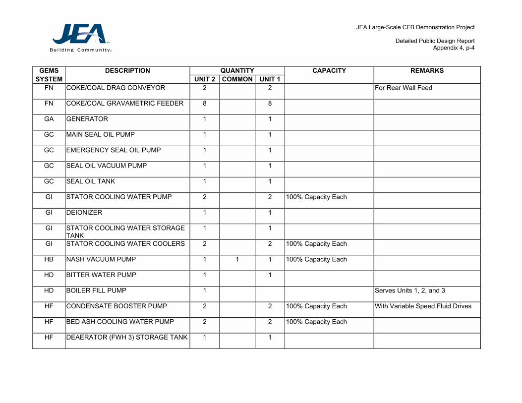
JEA Large-Scale CFB Demonstration Project
Detailed Public Design Report Appendix 4, p-4
GEMS DESCRIPTION QUANTITY CAPACITY REMARKS SYSTEM UNIT 2 COMMON UNIT 1
FN COKE/COAL DRAG CONVEYOR 2 2 For Rear Wall Feed
FN COKE/COAL GRAVAMETRIC FEEDER 8 8
GA GENERATOR 1 1
GC MAIN SEAL OIL PUMP 1 1
GC EMERGENCY SEAL OIL PUMP 1 1
GC SEAL OIL VACUUM PUMP 1 1
GC SEAL OIL TANK 1 1
GI STATOR COOLING WATER PUMP 2 2 100% Capacity Each
GI DEIONIZER 1 1
GI STATOR COOLING WATER STORAGE TANK
1 1
GI STATOR COOLING WATER COOLERS 2 2 100% Capacity Each
HB NASH VACUUM PUMP 1 1 1 100% Capacity Each
HD BITTER WATER PUMP 1 1
HD BOILER FILL PUMP 1 Serves Units 1, 2, and 3
HF CONDENSATE BOOSTER PUMP 2 2 100% Capacity Each With Variable Speed Fluid Drives
HF BED ASH COOLING WATER PUMP 2 2 100% Capacity Each
HF DEAERATOR (FWH 3) STORAGE TANK 1 1

JEA Large-Scale CFB Demonstration Project
Detailed Public Design Report Appendix 4, p-5
GEMS DESCRIPTION QUANTITY CAPACITY REMARKS SYSTEM UNIT 2 COMMON UNIT 1
HF DEAERATOR (FWH 3) HEATER SECTION
1 1
HF FEED WATER HEATER NO. 4 1 1
HF FEED WATER HEATER NO. 5 1 1
HF FEED WATER HEATER NO. 6 1 1
HK HEATER DRAIN PUMP 2 2 100% Capacity Each
HK FEED WATER HEATER NO. 6 HOTWELL
1 1
HP SULFURIC ACID MIXING SKID 1
HP CAUSTIC MIXING SKID 1
HP POLISHER RECYCLE PUMP 1 1
HP POLISHER SLUICE PUMP 1
HP POLISHER REGENERATION WATERPUMP
1
HP CAUSTIC RECYCLE PUMP 1
HP CONDENSATE POLISHER VESSEL 3 3 50% Capacity Each
HP CONDENSATE POLISHERSEPARATION AND ANION REGENERATION VESSEL
1 1
HP CONDENSATE POLISHER CATION REGENERATION VESSEL
1 1
HP CONDENSATE POLISHER MIX AND HOLD VESSEL
1 1

JEA Large-Scale CFB Demonstration Project
Detailed Public Design Report Appendix 4, p-6
GEMS DESCRIPTION QUANTITY CAPACITY REMARKS SYSTEM UNIT 2 COMMON UNIT 1
HP CONDENSATE POLISHER HOT WATER TANK
1 1
HP WASTE INSPECTION TANK 1
HP POLISHER RESIN TRAP 3 3 One per Polisher Vessel
IB TRAVELING WATER SCREENS 2 2 50% Capacity Each
IB SCREEN WASH PUMPS 2 Serve Units 1, 2, and 3
MA BOILER FREIGHT ELEVATOR 1 1
MJ BOILER SAMPLE PANEL CHILLER 1 1
MJ BOILER SAMPLE PANEL 1 1
MJ SAMPLE PANEL 1
MJ SAMPLE CHILLER 1
NA FLY ASH SILO 1 1 Fly Ash from either Unit 2 or Unit 1 can be directed to either silo
NA FLY ASH SILO FILTER/SEPARATOR 2 2 100% Capacity Each Fly Ash from either Unit 2 or Unit 1 can be directed to either silo
NA FLY ASH SILO VENT FILTER 1 1
NA AQCS RECYCLE BIN FILTER/SEPARATOR
1 1
NA FLY ASH HEAD CIRCULATION PUMP 1 1
NA DENSE ASH SLURRY MIXING TANK FEED PUMP
2 2 50% Capacity Each
NA STANDBY AIR COMPRESSOR 1

JEA Large-Scale CFB Demonstration Project
Detailed Public Design Report Appendix 4, p-7
GEMS DESCRIPTION QUANTITY CAPACITY REMARKS SYSTEM UNIT 2 COMMON UNIT 1
NA PRIMARY AIR COMPRESSOR 1
NA FLY ASH SLURRY MIXING TANK 1 1
NA FLY ASH VACUUM EXHAUSTER 4 100% Capacity Each Crosstied to serve either Unit 2 or Unit 1
NA BED ASH CROSS CONVEYOR 2 Between Unit 2 and Unit 1 Bed Ash Silo Outlets
NA BED ASH CLINKER GRINDERS 1 1 Above Dense Ash Slurry Mixing Tank
NA DENSE ASH SLURRY MIXING TANK 1 1
NA DENSE ASH HEAD CIRCULATION PUMP
1 1
NA DENSE ASH SLURRY BOOSTER PUMP 2 2 100% Capacity Each
NA DENSE ASH SLURRY PISTON DIAPHRAGM PUMP
2 100% Capacity Each
NA EMERGENCY FLUSH PUMP 1
NB BED ASH SILO 1 1 Bed Ash from either Unit 1 or Unit 2 can be directed to either silo
NB BED ASH PRESSURE AIRLOCK VESSEL
4 4
NB BED ASH SURGE HOPPER 1 1
NB SIDE WALL STRIPPER/ COOLER 2 2
NB FRONT WALL STRIPPER COOLER 2 2
NB BED ASH SURGE HPR. VENT FILTER 1 1
NB BED ASH SILO VENT FILTER 1 1

JEA Large-Scale CFB Demonstration Project
Detailed Public Design Report Appendix 4, p-8
GEMS DESCRIPTION QUANTITY CAPACITY REMARKS SYSTEM UNIT 2 COMMON UNIT 1
NB ASH CLR. DISCHARGE CONVEYOR 4 4 One from each Stripper Cooler
NB BED ASH GATHERING CONVEYOR 2 2
NB BED ASH CLINKER GRINDER 2 2 Above Bed Ash Surge Hopper
NB BED ASH TRANSPORT BLOWER 3 100% Capacity Each Crosstied to serve either Unit 2 or Unit 1
NB BED ASH SURGE HOPPER VENT FILTER EXHAUST FAN
1 1
NL REUSE WATER ACID FEED PUMP SKID
1
NL REUSE WATER INHIBITOR FEED PUMP SKID
1
NL REUSE WATER CHEMICAL FEED STATIC MIXER
1
NL REUSE WATER SUPPLY PUMP 2 100% Capacity Each
NL CSU REUSE WATER BOOSTER PUMP 1
NL REUSE WATER STORAGE TANK 1
NN BSA SUMP 4
NN BSA SUMP PUMPS 8 Two Pumps per Sump
NN BSA LEACHATE DETECTION SUMP 4
NN BSA LEACHATE DETECTION SUMP PUMP
8 Two Pumps per Sump
NN BSA POND EFFLUENT SUMP 1
NN BSA POND EFFLUENT SUMP PUMP 2

JEA Large-Scale CFB Demonstration Project
Detailed Public Design Report Appendix 4, p-9
GEMS DESCRIPTION QUANTITY CAPACITY REMARKS SYSTEM UNIT 2 COMMON UNIT 1
NN WASTEWATER COLLECTION SUMP 12 1
NN WASTEWATER COLLECTION SUMP 12 SUMP PUMP
2
NN FUEL STORAGE DOME SUMP 13 1
NN FUEL STORAGE DOME SUMP 13 SUMP PUMP
2
NN SUBSURFACE DRAIN SUMP 3
NN SUBSURFACE DRAIN SUMP PUMP 6 Two Pumps per Sump
NN BOILER SUMP 1 1
NN BOILER SUMP PUMP 2 2
NN AQCS SUMP 1 1
NN AQCS SUMP PUMP 2 2
NN ELEVATOR SHAFT SUMP PUMP 1 1
QB BOILER FEED PUMP 2 2 50% Capacity Each One motor driven, one turbine shaft driven. With variable speed fluid drives.
QB BOILER FEED PUMP SEAL WATER LEAK OFF RECOVERY TANK
1 1
QF FEED WATER HEATER NO. 2 1 1
QF FEED WATER HEATER NO. 1 1 1
RA AQCS GLYCOL CIRCULATING PUMP 2 100% Capacity Each Serve Unit 2 and Unit 1

JEA Large-Scale CFB Demonstration Project
Detailed Public Design Report Appendix 4, p-10
GEMS DESCRIPTION QUANTITY CAPACITY REMARKS SYSTEM UNIT 2 COMMON UNIT 1
RA AQCS ATOMIZING AIR COMPRESSOR 1 1 1 100% Capacity Each
RA AQCS ATOMIZING AIR RECEIVER 1 Serves Unit 2 and Unit 1
RA AQCS GLYCOL/WATER SURGE TANK 1 Serves Unit 2 and Unit 1
RA ATOMIZING AIR COMPRESSOR INLET AIR FILTER/SILER.
1 1 1 One per Compressor
RA ATOMIZING AIR COMPRESSORUNLOADING SILER.
1 1 1 One per Compressor
RA LIME SLURRY FEED PUMP 2 2 100% Capacity Each
RA RECYCLE SLURRY TRANS. PUMP 2 2 100% Capacity Each
RA FEED SLURRY TRANS. PUMP 2 2 100% Capacity Each
RA FEED SLURRY PUMP 2 2 100% Capacity Each
RA AQCS FLUIDIZING AIR BLOWER 3 3 50% Capacity Each
RA AQCS FLUIDIZING AIR HEATER 3 3 50% Capacity Each
RA LIME SLURRY STORAGE TANK AGITATOR
1 1
RA RECY SLURRY STORAGE TANK AGITATOR
1 1
RA RECY SLURRY MIX TANK AGITATOR 1 1
RA LIME SLURRY STORAGE TANK 1 1
RA RECYCLE SLURRY MIX TANK 1 1
RA RECYCLE SLURRY STORAGE TANK 1 1

JEA Large-Scale CFB Demonstration Project
Detailed Public Design Report Appendix 4, p-11
GEMS DESCRIPTION QUANTITY CAPACITY REMARKS SYSTEM UNIT 2 COMMON UNIT 1
RA FLY ASH RECYCLE STORAGE BIN 1 1
RA FEED SLURRY HEAD TANK 1 1
RA SDA BIN ACTIVATOR 1 1
RA FLY ASH RECYCLE FEEDER 2 2 100% Capacity Each
RA SDA ASH CONVEYOR 1 1
RA SDA EMERGENCY DISCHARGE CONVEYOR
1 1
RA SDA ASH DELUMPER 1 1
RA SDA IMPACTOR 3 3
RB FABRIC FILTER COMPARTMENT 8 8
RB AQCS INSTRUMENT AIR DRYER 2 100% Capacity Each Serve Unit 2 and Unit 1
RH LIMESTONE STACK-OUT CONVEYOR 1
RH LIMESTONE FEED CONVEYORS TO LS PREP
3 One per Dryer/Mill Train
RH LS PLANT AIR COMPRESSOR 2 Serve Unit 2 and Unit 1
RH LS AIR HEATER COMBUSTION AIR FAN
3 One per Dryer/Mill Train
RH LS DRYER/MILL DUST COLL EXHAUST FAN
3 One per Dryer/Mill Train
RH LS PREP. DUST COLLECTOR EXHAUST FAN
3 One per Dryer/Mill Train
RH LS PRODUCT PNEUMATIC BLOWER 3 One per Dryer/Mill Train

JEA Large-Scale CFB Demonstration Project
Detailed Public Design Report Appendix 4, p-12
GEMS DESCRIPTION QUANTITY CAPACITY REMARKS SYSTEM UNIT 2 COMMON UNIT 1
RH LS PLANT AIR RECEIVER 2 Serve Unit 2 and Unit 1
RH LIMESTONE PRODUCT SURGE BIN 3 One per Dryer/Mill Train
RH LS AIR HEATER 3 One per Dryer/Mill Train
RH LIMESTONE PREP. DUST COLLECTOR 3 One per Dryer/Mill Train
RH LIMESTONE DRYER/MILL DUST COLL 3 One per Dryer/Mill Train
RH LIMESTONE PRODUCT SCREEN 6 Two per Dryer/Mill Train
RH LS PLANT AIR DRYER 2 Serve Unit 2 and Unit 1
RH LIMESTONE PROD. ELEV CONVEYOR 3 One per Dryer/Mill Train
RH LIMESTONE SCREEN FEEDER 3 One per Dryer/Mill Train
RH LS SCREEN PRODUCT SCREW CONV. 3 One per Dryer/Mill Train
RH LIMESTONE DRYER/MILL 3 100% Capacity Each for 1 Unit
Each Dryer/Mill Train can supply either Unit 2 or Unit 1
RH RAW LIMESTONE IMPACTOR 3 One per Dryer/Mill Train
RL AQCS MILL RECYCLE FEED PUMP 2 100% Capacity Each Serve Unit 2 and Unit 1
RL AQCS LIME SLURRY TRANSFER PUMP
4 100% Capacity Each Serve Unit 2 and Unit 1
RL AQCS LIME SLURRY TRANS. TANK AGITATOR
2 Serve Unit 2 and Unit 1
RL AQCS LIME STORAGE SILO 1 Serves Unit 2 and Unit 1
RL AQCS LIME SLURRY TRANSFER TANK 2 Serves Unit 2 and Unit 1

JEA Large-Scale CFB Demonstration Project
Detailed Public Design Report Appendix 4, p-13
GEMS DESCRIPTION QUANTITY CAPACITY REMARKS SYSTEM UNIT 2 COMMON UNIT 1
RL AQCS MILL SEPARATING CHAMBER 2 Serves Unit 2 and Unit 1
RL AQCS LIME STORAGE SILO BIN ACTIVATOR
1 Serves Unit 2 and Unit 1
RL AQCS LIME STORAGE SILO DUST COLLECTOR
1 Serves Unit 2 and Unit 1
RL AQCS MILL VENT SCRUBBER 2 Serves Unit 2 and Unit 1
RL AQCS VERTICAL BALL MILL SLAKER 2 Serves Unit 2 and Unit 1
RN LIMESTONE BLOWER 3 3 33-1/3% Capacity Each
RN STANDBY LIMESTONE BLOWER 1 1
RN LIMESTONE SILO 1 1
RN LIMESTONE FILTER/RECEIVER 3 3
RN LIMESTONE SILO VENT FILTER 1 1
RN LIMESTONE FILTER/REC. EXHAUSTER 3 3
RN LIMESTONE ROTARY FEEDER 3 3
RN LIMESTONE ROTARY AIRLOCKFEEDER
6 6
RN LIMESTONE ROTARY VALVE 3 3
SI INTREX TM 3 3
SI INTREXTM BLOWER 3 3 50% Capacity Each
SI SEAL POT BLOWER 3 3 50% Capacity Each

JEA Large-Scale CFB Demonstration Project
Detailed Public Design Report Appendix 4, p-14
GEMS DESCRIPTION QUANTITY CAPACITY REMARKS SYSTEM UNIT 2 COMMON UNIT 1
SJ ERV SILENCER 1 1
SK CYCLONE 3 3
SL ECONOMIZER 1 1
TG STEAM TURBINE - LP 1 1
TH STEAM TURBINE - HP/IP 1 1
TI STEAM PACKING EXHAUSTER 1 1
TJ TURB LUBE OIL HEAT EXCHANGERS 2 2 100% Capacity Each
TJ TURBINE LUBE OIL CONDITIONER 2 2 One Bowser, One Turbo-Toc
TJ TURBINE LUBE OIL TANK 2 2 One Operating Tank, One Storage Tank
TJ TURBINE LUBE OIL PUMP 3 3 Two AC, One DC
TN TURBINE ELECTRO-HYDRAULICCONTROL UNIT
1 1
UE HYDRAZINE FEED PUMP 1 1
UE AMMONIA FEED PUMP 1 1
UE PHOSPHATE FEED PUMP 2 2 100% Capacity Each
UE PHOSPHATE STORAGE TANK 1 1
UE PHOSPHATE STG. TANK AGITATOR 1 1
UR AMMONIA PUMP 1 1 1 100% Capacity Each Common Shared Spare

JEA Large-Scale CFB Demonstration Project
Detailed Public Design Report Appendix 4, p-15
GEMS DESCRIPTION QUANTITY CAPACITY REMARKS SYSTEM UNIT 2 COMMON UNIT 1
UR AMMONIA STORAGE TANK 1 Serves Units 2 and 1
WF DEMINERALIZED WATER TRANSFER PUMPS
2 Added Demin Water from SJRPP for Units 1, 2, and 3
XE CONDENSATE PUMP 2 2 100% Capacity Each
XE CONDENSER 1 1
XE DEBRIS FILTERS 2 2 50% Capacity Each
XJ RIVER WATER BOOSTER PUMP 2 2 100% Capacity Each
XK CLOSED COOLING WATER PUMP 2 2 100% Capacity Each
XK CLOSED COOLING WATER BOOSTER PUMP
2 2 100% Capacity Each
XK CLOSED COOLING WATER SURGE TANK
1 1
XK CLOSED COOLING WATER PLATE HEAT EXCHANGER
2 2 100% Capacity Each
XL CIRCULATING WATER PUMP 2 2 50% Capacity Each

JEA Large-Scale CFB Demonstration Project
Detailed Public Design Report Appendix 4, p-16
JEA GROUP/SYSTEM DESCRIPTIONS
Group A Air .
System B Instrument C Service
Group B Boiler .
System A Acid Cleaning B Steam Generating Section C Air Preheater D Aspirating Air E Combustion Control F Burner Front H Electronic Control I Sootblowers J Casing and Structure K Vents and Drains N Combustion Air Flow O Combustion Gas Flow P Convection Pass S Service Steam T Seal Air W Wash Drains
Group D Diesel .
System A Engine/Generator B Starting
Group E Electrical .
System A Control Room Instrumentation B Plant Lighting and Dist. C Communication D 120-250V DC E Miscellaneous F MCC/Load Center/Switchgear G Switchyard
Group F Fuel .
System A Diesel Storage/Transfer B Natural Gas C Fuel Oil Service Pump D Fuel Oil Burner Supply/Return E Fuel Oil Heaters

JEA Large-Scale CFB Demonstration Project
Detailed Public Design Report Appendix 4, p-17
F Fuel Oil Storage/Transfer G Unloading Dock H Handling Solid Fuel I Ignitor Fuel Supply M Propane Gas N Day Silos P Pneumatic Transport R Rail Unloading Solid Fuel S Ship Unloader W Waste Derived V Vehicle Fuel Storage
Group G Generator .
System A Stator B Rotating Field C Seal Oil D Hydrogen E Exciter F Voltage Regulator G Protection Circuit H Isolated Phase I Stator Oil/Cooling Water
Group H Condensate .
System B Vacuum Supply D Supply E Recovery F Flow K Feedwater Heater Drains P Polishers
Group I Intake .
System A Crane B Traveling Screens D Canal E Sodium Hypochlorite
Group J Combustion Turbine .
System A Turning Gear B Accessory Station C Bearing/Coupling D Compressor Section E Lubricating Oil F Protection/Control G Combustor Section H Drains, Vents, and Inlet Bleed Heating I Housing

JEA Large-Scale CFB Demonstration Project
Detailed Public Design Report Appendix 4, p-18
J Closed Cycle Cooling Water K Compressor Water Wash L DEH Control N Exhaust O Supports Q Seal Oil R Starting S Turbine Section T Atomizing Air U Generator V CT CO2 and H2 Supply W Inlet Air Fogging X Water Injection
Group K Fire Protection .
System D Dry Chemical E Control Room F Foam J Gas Turbine P Portable W Water
Group L Environmental .
System A Meteorological B Air Quality Monitoring P Permitting W Groundwater Monitoring
Group M Miscellaneous .
System A Buildings and Grounds B Turbine Deck Bridge Crane C Bulk Instruments and Controls D Hydraulic Tools and Equip. E Pneumatic Tools and Equipment F Other Tools and Equipment G Electric Tools and Equipment H Machine Shop Equipment I Security J Laboratory K Plant Vehicles M Bulk Motors or Electrical O General Outage P Bulk Piping Q Overhead Costs R Freeze Protection S Startup U Bulk Insulation

JEA Large-Scale CFB Demonstration Project
Detailed Public Design Report Appendix 4, p-19
V Bulk Valves X Bulk Painting
Group N Waste .
System A Fly Ash B Bed Ash D Liquid Waste F Solid Waste Disposal L Sewage Treatment M Water Instrumentation N Water & Boiler Wash Collection P Pyrites U Waste Fuel Collection
Group O General Group Equipment .
Group P Ventilation .
System D Steam Heating G Air Conditioning J Equipment Dry Layup K Misc. Vents and Exhausts
Group Q Feedwater .
System B Boiler Feedwater Pump C BFP Steam Turbine D BFP Fluid Drive E Auxiliary Feedwater F Flow G BFP Steam Turbine Lube Oil
Group R Air Quality Control System (AQCS) .
System A Absorber Scrubber B Baghouse E Controls G Absorber (reserved for future) H Handling Limestone L Lime Preparation N Day Silos P Precipitator R Rail Unloading Limestone S Ship Unloading Limestone

JEA Large-Scale CFB Demonstration Project
Detailed Public Design Report Appendix 4, p-20
Group S Steam .
System A Auxiliary Piping C Auxiliary Boiler D Extraction Piping E Reheat Piping F Primary Superheating Section H Reheat Superheating Section I Secondary Superheating Section J Main Steam Piping K Cyclone Superheating Section L Heat Recovery Area Superheating Section
Group T Steam Turbine .
System A Front Standard B HP Section C Pedestal G LP Section H HP/IP Section I Steam Seals J Lubricating Oil K Vents and Drains L HP/IP Turbine Control M Supervisory Instrumentation N Turbine Controls S Structure X Crossover Pipe
Group U Chemical .
System A Nitrogen Supply C CO2 and H2 Supply D Condenser Discharge Chemical Injection E Condensate Chemical Injection L Boiler Wash M Miscellaneous R AQCS S Solid Fuel Treatment Y Fuel Oil Treatment
Group W Water .
System A Treatment Plant Filtering B Treatment Plant Brine D Treatment Plant Acid E Treatment Plant Caustic F Demineralizer

JEA Large-Scale CFB Demonstration Project
Detailed Public Design Report Appendix 4, p-21
H Water Supply K Potable Water Supply
Group X Cooling Water .
System E Condenser G Condenser Cleaning J River Water K Closed Cooling L Circulating Water

JEA Large-Scale CFB Demonstration Project
Detailed Public Design Report Appendix 5, p-1
APPENDIX 5
PROJECT MILESTONE SCHEDULE
The Project Milestone Schedule on the following pages lists the significant milestone dates associated with the Repowering Project. Milestone dates are indicated for Unit 2 and Common Facilities, and also for Unit 1, since the Unit 1 project activities were implemented with only a planned three month lag behind Unit 2 and Common Facilities.

JEA Large-Scale CFB Demonstration Project
Detailed Public Design Report Appendix 5, p-2
PROJECT MILESTONE SCHEDULE
MILESTONEAug-99 Original Baseline
Feb-00 Updated Baseline
Sep-01 Updated Baseline
Jul-02 Approved
DOE ScheduleActual
Completion
JEA Large-Scale CFB Combustion Demonstration Project Cooperative Agreement Signed
27-Sep-97 27-Sep-97 27-Sep-97 27-Sep-97 27-Sep-97
DOE PHASE 1
1.1 PROJECT MANAGEMENT Project Management Plan 30-Sep-99 7-May-99 7-May-99 7-May-99 7-May-99 Public Design Report Not Sched Not Sched Not Sched 6-Nov-02 Environmental Monitoring Plan 2-Dec-99 2-Dec-99 2-Dec-99 2-Dec-99 2-Dec-99
1.2 PERMITTING NEPA Completion 21-Oct-99 7-Dec-00 7-Dec-00 7-Dec-00 7-Dec-00 FACE Water Permit 30-Jul-99 30-Jul-99 30-Jul-99 30-Jul-99 30-Jul-99 ERP Permit 27-Jul-99 27-Jul-99 27-Jul-99 27-Jul-99 27-Jul-99 NPDES Water Permit 13-Dec-99 15-Feb-00 15-Feb-00 15-Feb-00 15-Feb-00
1.3 PRELIMINARY DESIGN 3-Aug-98 3-Aug-98 3-Aug-98 3-Aug-98 3-Aug-98
1.4 DESIGN / ENGINEERING Notice To Proceed Boiler / AQCS 3-Aug-98 3-Aug-98 3-Aug-98 3-Aug-98 3-Aug-98 Balance of Plant 1-Feb-99 1-Feb-99 1-Feb-99 1-Feb-99 1-Feb-99 Material Handling 1-Feb-99 1-Feb-99 1-Feb-99 1-Feb-99 1-Feb-99 40% Design Review 14-Jun-99 14-Jun-99 1 14-Jun-99 4-Jun-99 14-Jun-99 90% Design Review 8-Sep-00 8-Sep-00 18-May-00 18-May-00 18-May-00
1.5 FUELS SELECTION STUDY 17-Oct-00 17-Oct-00 Not Presented 9-Sep-02

JEA Large-Scale CFB Demonstration Project
Detailed Public Design Report Appendix 5, p-3
MILESTONE Aug-99 Original Baseline
Feb-00 Updated Baseline
Sep-01 Updated Baseline
Jul-02 Approved
DOE ScheduleActual
Completion DOE PHASE 2
2.1 PROJECT MANAGEMENT Project Management Plan Update Not Sched Not Sched Not Sched 9-Sep-02 Environmental Monitoring Not Sched Not Sched Not Sched Not Sched Not Sched Startup Modification & Performance Report Not Sched Not Sched Not Sched 6-Jan-03 50% Construction Review 10-Nov-00 10-Nov-00 25-Jan-01 25-Jan-01 25-Jan-01 100% Construction Review 14-Dec-01 14-Dec-01 14-Aug-01 14-Aug-01 14-Aug-01
2.3 BOILER EQUIPMENT & AQCS Notice to Proceed 16-Aug-99 16-Aug-99 16-Aug-99 16-Aug-99 16-Aug-99 Unit 2 - Boiler Island Foundations 17-Dec-99 20-Jan-00 20-Jan-00 20-Jan-00 20-Jan-00 Unit 2 - Boiler Steel Erection 29-May-01 31-May-01 23-May-01 23-May-01 23-May-01 Unit 2 - Raise Steam Drum 1-Jun-00 1-Jun-00 3-Jun-00 3-Jun-00 3-Jun-00 Unit 2 - Hydrotest 29-May-01 14-Jun-01 23-May-01 23-May-01 23-May-01 Unit 2 - Chemical Cleaning 1-Oct-01 1-Oct-01 10-Sep-01 10-Sep-01 10-Sep-01 Unit 2 - First Fire (Gas) 2-Jul-01 5-Oct-01 t-01 30-Oc 30-Nov-01 30-Nov-01 Unit 2 - Steam Blows 1-Feb-02 8-Oct-01 15-Nov-01 3-Jan-02 3-Jan-02 Unit 2 - First Fire (Solid Fuel) 1-Oct-01 13-Oct-01 2-Dec-01 14-Feb-02 14-Feb-02 Unit 2 - Intial Sync 1-May-02 9-Oct-01 1-Dec-01 19-Feb-02 19-Feb-02 Unit 2 - Preliminary Substantial Completion 8-Aug-02 2-Jan-02 14-Feb-02 18-Jul-02 Unit 2 Reliability Test 1-Feb-02 1-Feb-02 1-Apr-02 13-Sep-02 Unit 2 - Substantial Completion 8-Nov-02 4-Apr-03 15-May-02 19-Sep-02 Unit 1 - Boiler Island Foundations 26-Apr-00 9-Feb-00 9-Feb-00 9-Feb-00 9-Feb-00 Unit 1 - Boiler Steel Erection 28-Aug-01 18-Sep-01 17-Au 17-Aug-01 g-01 17-Aug-01 Unit 1 - Raise Steam Drum 27-Sep-00 6-Sep-00 11-Sep-00 11-Sep-00 11-Sep-00 Unit 1 - Hydrotest 28-Aug-01 18-Sep-01 27-Sep-01 4-Oct-01 4-Oct-01 Unit 1 - Chemical Cleaning 8-Jan-02 23-Jan-02 18-Dec-01 18-Feb-02 18-Feb-02 Unit 1 - First Fire (Gas) 8-Aug-02 20-Sep-02 3-Feb-02 13-Mar-02 13-Mar-02

JEA Large-Scale CFB Demonstration Project
Detailed Public Design Report Appendix 5, p-4
MILESTONE Aug-99 Original Baseline
Feb-00 Updated Baseline
Sep-01 Updated Baseline
Jul-02 Approved
DOE ScheduleActual
Completion Unit 1 - Steam Blows 1-Feb-02 30-Oct-02 17-Feb-02 7-Apr-02 7-Apr-02 Unit 1 - First Fire (Solid Fuel) 6-Sep-02 18-Oct-02 12-Mar-02 31-May-02 31-May-02 Unit 1 - Intial Sync 6-Sep-02 17-Oct-02 11-Mar-02 29-May-02 29-May-02 Unit 1 - Preliminary Substantial Completion 8-Aug-02 27-Dec-02 2-Jun-02 22-Sep-02 Unit 1 - Reliability Test 10-Sep-02 29-Jan-03 24-Jun-02 21-Nov-02 Unit 1 - Substantial Completion 8-Nov-02 1-Apr-03 31-Aug-02 21-Nov-02
2.4 BALANCE OF PLANT Notice to Proceed 27-Jul-99 27-Jul-99 27-Jul-99 27-Jul-99 27-Jul-99 Unit 2 - BOP Completion 4-Sep-01 9-Nov-01 17-Jan-02 8-Mar-02 8-Mar-02 Unit 1 - Cutover Outage Not Sched Not Sched 15-Sep-01 15-Sep-01 15-Sep-01 Unit 1 - BOP Completion 1-May-02 31-May-02 14-Jan-02 12-Apr-02 12-Apr-02
2.5 MATERIAL HANDLING EQUIPMENT Conveyor Mechanically Complete 10-Aug-01 -01 10-Jul 23-Oct-01 7-Nov-01 7-Nov-01 Continuous ShipUnloader 17-Jul-01 4-Jun-01 3-Oct-01 3-Oct-01 3-Oct-01 Fuel Storage Dome"A" - Stacker Reclaimer 20-Feb-01 12-Jun-01 28-Sep-01 28-Sep-01 28-Sep-01 Fuel Storage Dome"B" - Stacker/Reclaimer 29-Aug-01 29-Aug-01 13-Nov-01 30-Nov-01 30-Nov-01
2.6 TURBINE / GENERATOR REFURBISHMENT Unit 2 - Turbine Refurbishment 5-Oct-01 11-Jul-01 23-Nov-01 15-Feb-02 15-Feb-02 Unit 1 - Turbine Refurbishment 1-May-02 1-May-02 3-Feb-02 12-Apr-02 12-Apr-02
DOE PHASE 3
3.1 PROJECT MANAGEMENT Project Management Plan Update Not Sched Not Sched Not Sched 9-Sep-02 Environmental Monitoring / Test Plan Not Sched Not Sched Not Sched 23-Sep-02 Public Design Report Not Sched Not Sched Not Sched 6-Nov-02
JEA Large-Scale CFB Demonstration Project
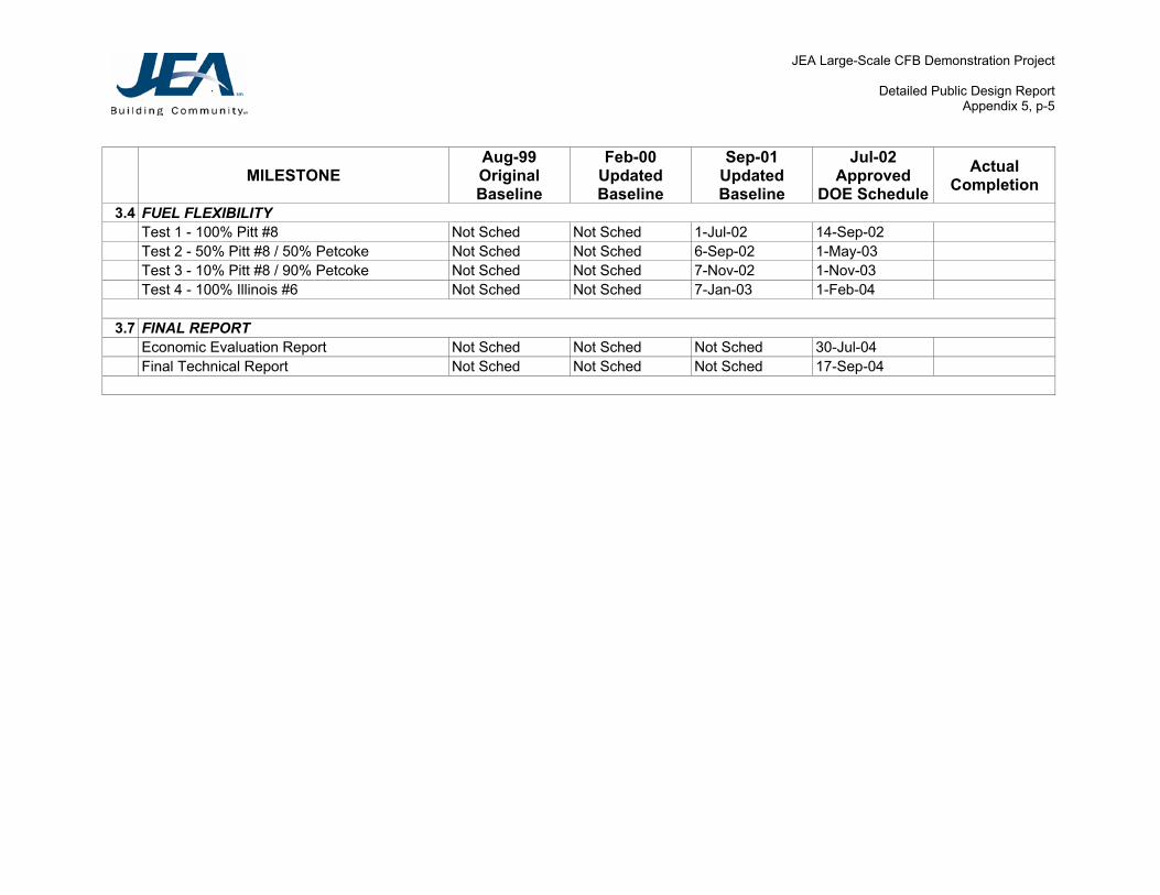
Detailed Public Design Report Appendix 5, p-5
MILESTONE Aug-99 Original Baseline
Feb-00 Updated Baseline
Sep-01 Updated Baseline
Jul-02 Approved
DOE ScheduleActual
Completion 3.4 FUEL FLEXIBILITY
Test 1 - 100% Pitt #8 Not Sched Not Sched 1-Jul-02 14-Sep-02 Test 2 - 50% Pitt #8 / 50% Petcoke Not Sched Not Sched 6-Sep-02 1-May-03 Test 3 - 10% Pitt #8 / 90% Petcoke Not Sched Not Sched 7-Nov-02 1-Nov-03 Test 4 - 100% Illinois #6 Not Sched Not Sched 7-Jan-03 1-Feb-04
3.7 FINAL REPORT Economic Evaluation Report Not Sched Not Sched Not Sched 30-Jul-04 Final Technical Report Not Sched Not Sched Not Sched 17-Sep-04

JEA Large-Scale CFB Demonstration Project
Detailed Public Design Report Appendix 6, p-1
APPENDIX 6
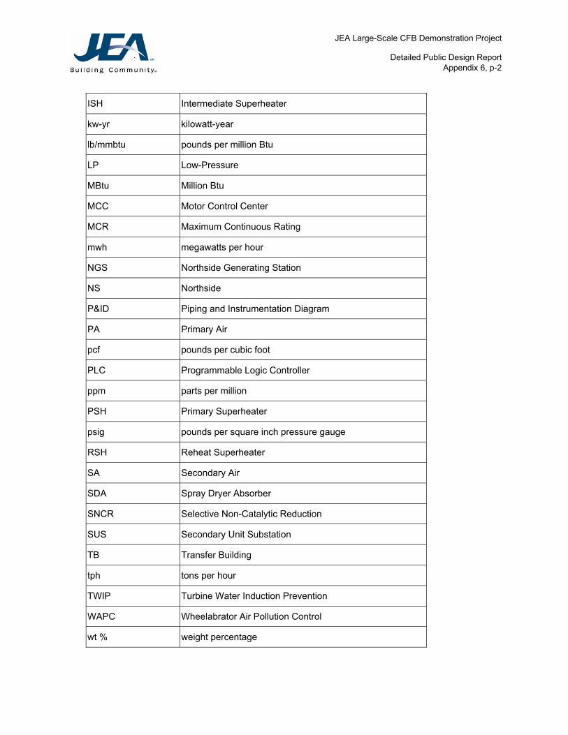
ABBREVIATION LIST Following is a definition of abbreviations used in this report. Note that at their first use, these terms are fully defined in the text of the report, followed by the abbreviation in the parenthesis. Subsequent references use the abbreviation only.
Abbreviation Definition
AQCS Air Quality Control System
BC Belt Conveyor
BF Belt Feeder
BMS Burner Management System
BOP Balance of Plant
BSA Byproducts Storage Area
btu British Thermal Unit
CFB Circulating Fluidized Bed
DCS Distributed Control System
DOE Department of Energy
FF Fabric Filter
FSH Final Steam Heating
FWEC Foster Wheeler Energy Corp.
FWUSA Foster Wheeler USA
gpm gallons per minute
gr/acf grains per actual cubic foot
gr/dscf grains per dry standard cubic foot
HHV Higher Heating Value
HP High-Pressure
HRA Heat Recovery Area
ID Induced Draft
IP Intermediate Pressure
JEA Large-Scale CFB Demonstration Project
Detailed Public Design Report Appendix 6, p-2
ISH Intermediate Superheater
kw-yr kilowatt-year
lb/mmbtu pounds per million Btu
LP Low-Pressure
MBtu Million Btu
MCC Motor Control Center
MCR Maximum Continuous Rating
mwh megawatts per hour
NGS Northside Generating Station
NS Northside
P&ID Piping and Instrumentation Diagram
PA Primary Air
pcf pounds per cubic foot
PLC Programmable Logic Controller
ppm parts per million
PSH Primary Superheater
psig pounds per square inch pressure gauge
RSH Reheat Superheater
SA Secondary Air
SDA Spray Dryer Absorber
SNCR Selective Non-Catalytic Reduction
SUS Secondary Unit Substation
TB Transfer Building
tph tons per hour
TWIP Turbine Water Induction Prevention
WAPC Wheelabrator Air Pollution Control
wt % weight percentage