
The Engineering Drawings will be explained in two parts. · PDF fileReading Eng and Shop...
5
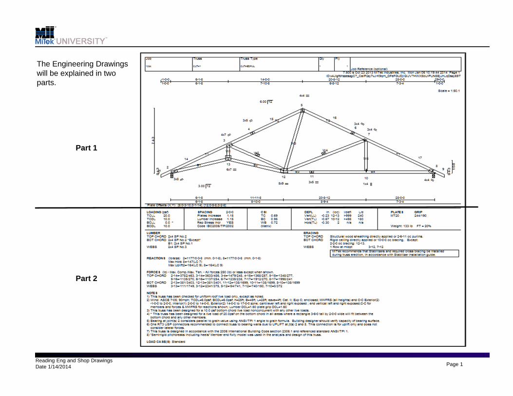
Reading Eng and Shop Drawings Date 1/14/2014 Page 1 The Engineering Drawings will be explained in two parts. Part 1 Part 2
Transcript of The Engineering Drawings will be explained in two parts. · PDF fileReading Eng and Shop...
Reading Eng and Shop DrawingsDate 1/14/2014 Page 1
The Engineering Drawings will be explained in two parts.
Part 1
Part 2
Reading Eng and Shop DrawingsDate 1/14/2014 Page 2
1 2 3 4 5 6
78
9
10
11
12
13
14
15
16
17 18
19
20
2
3
4
5
6
7
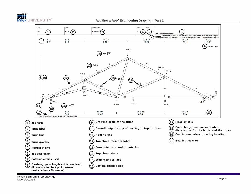
Job name
Truss label
Truss type
Truss quantity
Number of plys
Job description
Software version used
8 Overhang, panel length and accumulated dimensions for the top of the truss (feet – Inches – Sixteenths)
9
10
11
12
13
14
Drawing scale of the truss
Overall height – top of bearing to top of truss
Heel height
Top chord member label
Connector size and orientation
Top chord slope
1
15
16
Web member label
Bottom chord slope
Reading a Roof Engineering Drawing – Part 1
Panel length and accumulated dimensions for the bottom of the trussContinuous lateral bracing location
17
18
19
Plate offsets
20 Bearing location

Reading Eng and Shop DrawingsDate 1/14/2014 Page 3
21 2224
2325 26 27 28
29
30
22
23
24
25
26
27
Design Loading (PSF)
Spacing on center (feet – Inches – Sixteenths)
Duration of Load for plate and lumber design
Design code
Top chord, bottom chord and web maximum CSI
Deflections (inches) and span to deflection ratio
Input span to deflection ratio
28 MiTek plate allowables (PSI)
29
30
Lumber requirements
Reaction (pounds) Bearing size - input & min required
21
Reading a Roof Engineering Drawing – Part 2
31
32
31
32
33
34
33
34
35
35
Maximum uplift and/or horizontal reaction if applicable
Required member bracing
Maximum member forces Tension (+) Compression (-)
Notes
Additional loads / load cases
Reading Eng and Shop DrawingsDate 1/14/2014 Page 4
1 2 3 4 5 6
7
8 910
11
12
13
14
16
17 15 18
1
2
3
4
5
6
7
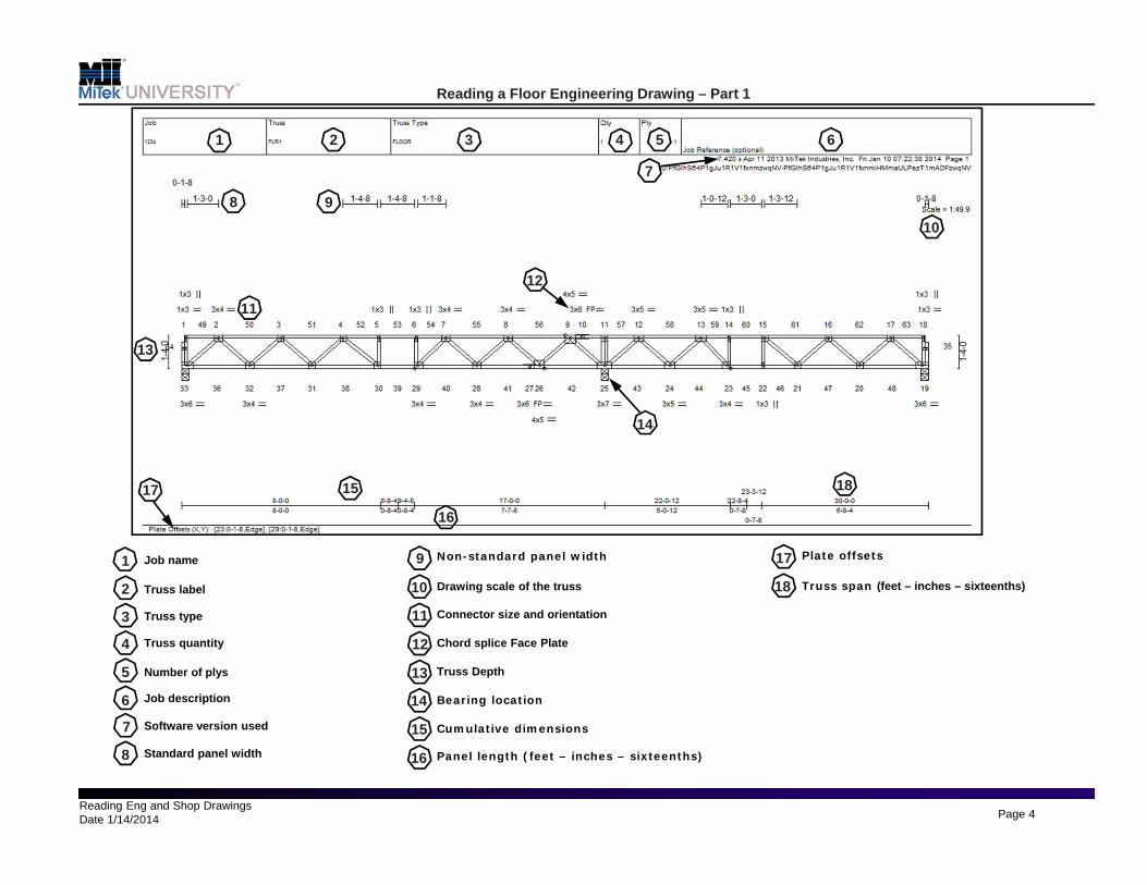
Job name
Truss label
Truss type
Truss quantity
Number of plys
Job description
Software version used
8 Standard panel width
9
10
11
12
13
14
Non-standard panel width
Drawing scale of the truss
Connector size and orientation
Chord splice Face Plate
Truss Depth
Bearing location
15
16
Cumulative dimensions
Panel length (feet – inches – sixteenths)
Reading a Floor Engineering Drawing – Part 1
Truss span (feet – inches – sixteenths)
17
18
Plate offsets

Reading Eng and Shop DrawingsDate 1/14/2014 Page 5
21 22 24
23
25 26 27 28
29 30
22
23
24
25
26
27
Design Loading (PSF)
Spacing on center (feet – Inches – Sixteenths)
Duration of Load for plate and lumber design
Design code
Top chord, bottom chord and web maximum CSI
Deflections (inches) and span to deflection ratio
Input span to deflection ratio
28 MiTek plate allowables (PSI)
29
30
Lumber requirements
Reaction (pounds) Bearing size - input & min required
21
Reading a Floor Engineering Drawing – Part 2
31
32
31
32
33
34
33
34
35
35
Maximum uplift and/or horizontal reaction if applicable
Required member bracing
Maximum member forces Tension (+) Compression (-)
Notes
Additional loads / load cases