The Efficacy of Friction Stir Welding in High Strength ...met.sdsmt.edu/reu/2013/3/2.Report/Final...
42
The Efficacy of Friction Stir Welding in High Strength Steel Production Prepared by: Timothy S. Fountain Faculty Advisors: Dr. Michael West Back to the Future REU Site Director, Department of Materials and Metallurgical Engineering Dr. Bharat Jasthi Associate Professor, Department of Materials and Metallurgical Engineering Dr. Alfred Boysen Professor, Department of Humanities Other Advisors: Cory Anthony Chief Metallurgist, Nucor Steel, Utah Program Information: National Science Foundation Grant NSF #DMR-1157074 Grant CFSP #ENG-0934383 Research Experience for Undergraduates Summer 2013 South Dakota School of Mines and Technology 501 E Saint Joseph Street Rapid City, SD 57701
Transcript of The Efficacy of Friction Stir Welding in High Strength ...met.sdsmt.edu/reu/2013/3/2.Report/Final...

3
The Efficacy of Friction Stir Welding in High
Strength Steel Production
Prepared by:
Timothy S. Fountain
Faculty Advisors:
Dr. Michael West
Back to the Future REU Site Director, Department of Materials and Metallurgical Engineering
Dr. Bharat Jasthi
Associate Professor, Department of Materials and Metallurgical Engineering
Dr. Alfred Boysen
Professor, Department of Humanities
Other Advisors:
Cory Anthony
Chief Metallurgist, Nucor Steel, Utah
Program Information:
National Science Foundation
Grant NSF #DMR-1157074
Grant CFSP #ENG-0934383
Research Experience for Undergraduates
Summer 2013
South Dakota School of Mines and Technology
501 E Saint Joseph Street
Rapid City, SD 57701
4
Table of Contents Abstract ................................................................................................................................................. 1
Introduction .......................................................................................................................................... 1
Background ........................................................................................................................................ 1
Tool Materials .................................................................................................................................... 4
Process Parameters and Other Considerations ................................................................................ 7
Objectives ........................................................................................................................................... 8
Broader Impact .................................................................................................................................... 9
Procedure............................................................................................................................................. 10
Materials .......................................................................................................................................... 10
Tool Selection ................................................................................................................................... 10
Welding ............................................................................................................................................ 11
Developmental Bead on Plate Welds .................................................................................................. 11
Joined Pieces .................................................................................................................................... 13
Double Pass Welds ............................................................................................................................ 13
Heat Treatment .................................................................................................................................. 13
Microstructural Analysis ................................................................................................................. 14
Metallography ................................................................................................................................... 14
Microhardness Testing ...................................................................................................................... 14
Mechanical Testing .......................................................................................................................... 15
Results .................................................................................................................................................. 15
Microstructural Analysis ................................................................................................................. 15
Metallography .................................................................................................................................. 15
Parent Material ................................................................................................................................. 16
Weld Nugget ...................................................................................................................................... 17
HAZ/TMAZ ........................................................................................................................................ 18
Double Pass Welds ............................................................................................................................ 21
Microhardness Testing .................................................................................................................... 23
Mechanical Properties ..................................................................................................................... 26
Tensile Testing ................................................................................................................................. 26
Parent Material ................................................................................................................................. 26
Single Pass Welds .............................................................................................................................. 27

5
Double Pass Welds ............................................................................................................................ 28
Discussion ............................................................................................................................................ 30
Microstructural Discrepancies ........................................................................................................ 30
Heat Treatment Optimization ......................................................................................................... 31
Martensite Phase Transformation and Sub-Critical Welding ....................................................... 32
Conclusion ........................................................................................................................................... 32
Summary .......................................................................................................................................... 32
Recommendations ............................................................................................................................ 34
Future Work .................................................................................................................................... 35
References ............................................................................................................................................ 36
Acknowledgments ................................................................................................................................ 38

1
Abstract
Friction stir welding (FSW) of proprietary grade-110 HSLA steel was completed. It was
found that FSW can effectively process and join this ultra-high strength material, though
questions about its efficiency in a production setting still remain. Material was evaluated in terms
of microstructure and tensile properties. All welds underwent phase transformations that resulted
in martensite formation in the weld nugget, which embrittled the material and lowered elongation
far below customer specifications. Post weld heat treatment restored hardness and ductility to
acceptable levels. Welds performed with successful parameters had yield and tensile strengths
within 97% or more of parent material values. Elongations were close to meeting customer
specifications, but require a different heat treatment to be most effective. Defects occurred in
welds with travel speeds of 10 ipm or greater, and also in double pass welds. These defects were
severely detrimental to mechanical properties but it is believed that they can be eliminated with
further parameter development and altered tool geometry.
Introduction
Background
Friction stir welding (FSW) is a joining practice patented by The Welding Institute of the
United Kingdom in 1991. It is unique in that it is a solid state welding technique, meaning that
no material actually melts during the process. Instead, a rotating tool is plunged into the weld
piece and uses heat generated by friction to plasticize the material to the point where it is soft
enough to be stirred together to form a joint. Plastic deformation generates additional heat. A
diagram of FSW can be found in Figure 1.
2
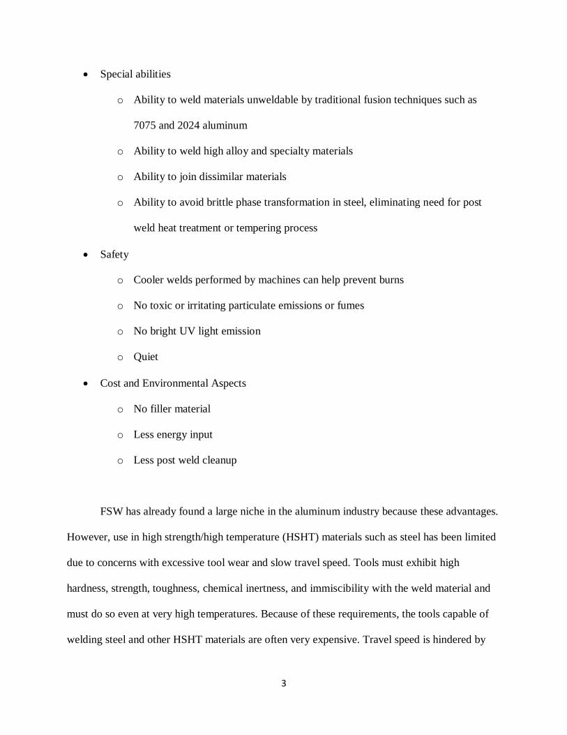
Because of the relatively low heat input and its ability to weld material without melting it,
FSW holds several advantages over traditional fusion welding techniques. These advantages
include the following:
Weld Quality and Mechanical Properties
o Smaller heat affected zone (HAZ)
o Forging, not casting process, that eliminates casting defects such as gas porosity
o Grain size reduction in the weld nugget
o Enhanced material properties in weld nugget
o Warping from high heat input is largely avoided or minimized
o Parent metal chemistry retained
o Consistent, defect free welds with correct parameters
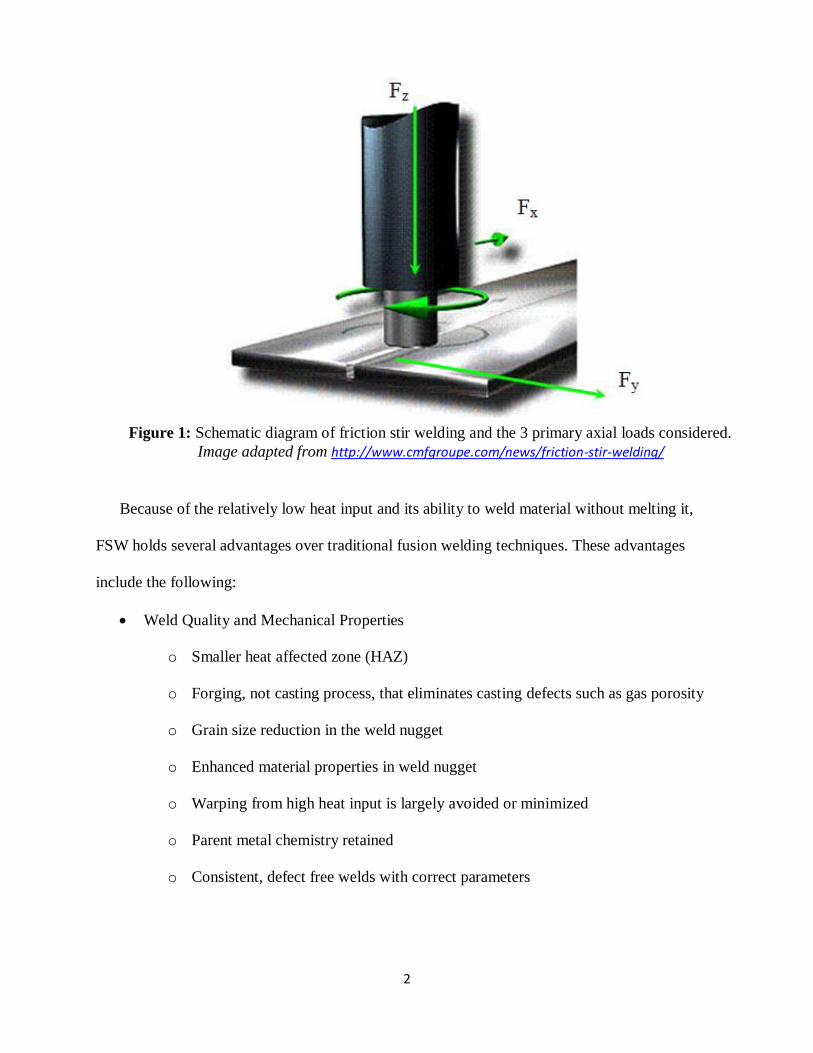
Figure 1: Schematic diagram of friction stir welding and the 3 primary axial loads considered.
Image adapted from http://www.cmfgroupe.com/news/friction-stir-welding/
3
Special abilities
o Ability to weld materials unweldable by traditional fusion techniques such as
7075 and 2024 aluminum
o Ability to weld high alloy and specialty materials
o Ability to join dissimilar materials
o Ability to avoid brittle phase transformation in steel, eliminating need for post
weld heat treatment or tempering process
Safety
o Cooler welds performed by machines can help prevent burns
o No toxic or irritating particulate emissions or fumes
o No bright UV light emission
o Quiet
Cost and Environmental Aspects
o No filler material
o Less energy input
o Less post weld cleanup
FSW has already found a large niche in the aluminum industry because these advantages.
However, use in high strength/high temperature (HSHT) materials such as steel has been limited
due to concerns with excessive tool wear and slow travel speed. Tools must exhibit high
hardness, strength, toughness, chemical inertness, and immiscibility with the weld material and
must do so even at very high temperatures. Because of these requirements, the tools capable of
welding steel and other HSHT materials are often very expensive. Travel speed is hindered by

4
tool capability and the tendency to form defects when the weld pitch (
) is too low
or too high.
This project was started in conjunction with Nucor Steel, Utah and will examine the
production feasibility of FSW in a proprietary microalloyed, high-strength-low-alloy (HSLA)
steel for use in a heavy duty structural application. At the time of this writing the specific
application and chemistry for this steel are confidential. The goal is to successfully butt weld two
angles together to form a channel. Tensile and fatigue properties are critical to its application.
Tool Materials
As noted above, one of the primary difficulties of friction stir welding steel and other
HSHT alloys is tool wear. Tools must be tough and both stronger and harder than the materials
being welded so that they have the ability to remain intact even in the rigorous service
environment they are subjected to. They also must be chemically inert and immiscible to their
service environment to prevent chemical wear in the tool and contamination of the weld. It is
important to mention that tool failure does not mean that the tool must be worn down to the nub
or shattered, it simply means that the tool can no longer create acceptable welds. Tool materials
are growing ever more advanced to combat these issues, but a new concern arises with cost.
Many of these tools cost between $1000 and $2000 per inch of material, making their use
prohibitive to industrial use especially if they are subject to failure. Tools can be ceramic,
metallic, or can be a composite of both.
Ceramic tools are known for their superior hardness and subsequent resistance to abrasive
wear, but are also known for their susceptibility to brittle shattering under high loads or impacts.
A common, and probably the best, ceramic tool used in HSHT materials is polycrystalline cubic
boron nitride (PCBN). PCBN is second in hardness only to diamond, making it ideal for the

5
abrasive service environment encountered in FSW. Like most ceramics, however, PCBN can
experience brittle failure from impact or high stress. Even slight vibrations in the welder can lead
to failure of the tool without warning. There have been efforts to toughen this material by adding
tungsten rhenium (W-Re) particles to it, and this has been successful in friction stir spot welding
(FSSW) trials. Tools with 70% PCBN and 30% W-Re, also called Q-70 tools, have proven to be
capable of performing up to 1200 spot welds in high strength dual phase steel with little
degradation to weld quality. Q-60 tools, or tools with 60% PCBN and 40% W-Re, tend to wear
out and produce unacceptable welds before 1000 spot welds have been completed.
Another ceramic tool that draws considerable interest is silicon nitride (Si3N4). Though
not as wear resistant as PCBN, it is far less expensive to produce. It has been used effectively in
the friction stir spot welding of various advanced high strength steel (AHSS) alloys, though some
reports claim them to contaminate welds with Si and N when left uncoated. Reports that mention
contamination claim that tools coated in layers of titanium carbide and titanium nitride (TiC and
TiN) eliminate contamination, in effect improving weld quality and tool life.
Metallic tools are also used. Though not as hard as ceramics, they are far tougher and
hold the extra benefit of being able to be remachined and repaired. For aluminum alloys, tool
steel is acceptable, but for HSHT alloys a stronger material is needed. The most effective tools
used for HSHT materials are various tungsten-rhenium alloys.
Tungsten is known for its high strength and high melting temperature. However, it has a
high ductile to brittle transition temperature and is further embrittled when its recrystallization
temperature is exceeded. As a remedy, pure tungsten is alloyed with other materials that both
improve these properties and remain stable in the high temperature applications that tungsten is
6
often used in. Three primary alloys are considered when dealing with tungsten tools, and each
have different benefits. They include the following:
Tungsten-Lanthanum Oxide (W-LaO): LaO is added to W in amounts of about 1
weight percent to raise recrystallization temperature and increase creep strength.
Tungsten-Rhenium (W-Re): Re is added to W generally in amounts of 25% to
drastically reduce the ductile to brittle transition temperature (DBTT) and increase
the recrystallization temperature. The effect is a much tougher material. This
improvement in properties is known as the rhenium effect.
Tungsten-Rhenium-Hafnium Carbide (W-Re25-HfC): To further improve upon
the properties of W-Re, HfC can be added in amounts generally between 2-10%.
HfC precipitates along grain boundaries and reduces grain size, thus increasing
strength in addition to the toughness obtained through the rhenium effect.
W-LaO is generally the least effective tool material of those listed above due to its
tendency to experience plastic deformation after time or in extremely rigorous service
environments. Pure W-Re25 is a much more effective tool material than W-LaO, but still can
experience significant deformation due to twinning. W-Re-HfC are the best tools of those listed
and experience very little wear even over time and in rigorous service environments. When they
fail, small particles break off intergranularly and are stirred into the weld material. Previous
studies have noticed this loss and contamination as minimal and have reported no degradation to
weld quality. Based on the author’s observations in research and literature, W-Re25-HfC is the
most effective metallic tool used in the FSW of steel to date.

7
Process Parameters and Other Considerations
In FSW three parameters are generally considered. They are forge force, spindle speed,
and weld travel speed. Forge force is the Z-force (downward force, see Figure 1) applied by the
tool on the weld piece and is measured in units such as Newtons or pounds. Forge force helps
keep the hot, plasticized material consolidated during the welding process. It also generates
frictional heat from the rubbing of the shoulder on the surface of the weld material. Spindle
speed is the speed at which the tool rotates and is generally measured in revolutions per minute.
The faster the tool rotates, the more heat from friction and plastic deformation is generated.
Travel speed is the speed at which the tool moves along the weld path and can be measured in
units such as inches per minute, millimeters per minute, etc. Travel speed is very important in
production because it determines how quickly a product can be produced. However, care must be
taken to balance travel speed with proper spindle speed because a weld with too low or too high
of a weld pitch (
) will result in defects. The goal is to balance these parameters
and find a so called “process envelope” for the material. A graphical diagram of this idea can be
below in Figure 2.
Figure 2. Graphical representation of the balancing of weld parameters in FSW.

8
A weld with a high travel speed (ipm) and a low rotational speed (rpm) will generate little
heat per unit of weld distance. The rotation of the tool is primarily what generates heat from
friction and plastic deformation, and if the weld is travelling too fast for the given spindle speed
then too little heat is generated. A weld with too little heat is termed “cold” and can form defects.
Likewise, too high of a rotational speed will also create defects known as “hot” defects. These
parameters must be balanced so that just enough heat is generated for the given travel speed. The
goal of industry is to find the top edge of the process envelope, maximizing the travel speed that
can be obtained while still maintaining sound, defect free welds. However, this balancing cannot
continue ad infinitum. When these parameters are pushed too high other defects happen, and it is
also likely that the welding machine and tool will have limitations that prevent further
development.
The procedure for developing this process envelope is essentially a trial and error
process. Welds are attempted at a certain set of parameters, and then those parameters are
evaluated based on the presence of any defects, microstructure, and mechanical properties. The
goal is to push the boundaries and find at which points weld qualities to break down. When those
boundaries are found it is then possible to say that if welds are made within those boundaries, a
quality joint will be created.
Objectives
The first portion of this project will examine the joining of proprietary grade-110 HSLA steel
with FSW. Determining production feasibility of FSW for this application will involve
examination for defects, characterization of the microstructural changes that take place during
welding, and an evaluation of mechanical properties to ensure that customer specifications can
be met. Another important consideration will be a quantitative tool wear study, but that is beyond

9
the scope of this paper. In the future these results will be compared to two competing welding
styles, tandem MIG and hybrid laser arc welding. Customer specifications include the following:
120 ksi Yield Strength
130 ksi Tensile Strength
12% Elongation
The goal of this project is to develop sound, defect free welds using FSW and to see if those
parameters can be optimized to become a worthwhile production practice in the steel industry.
Broader Impact
With engineering safety requirements growing more stringent while consumers hunt for
lower prices and lighter weight materials, a new breed of steels is being developed. These
include various HSLA alloys and advanced high strength steels (AHSS) that require less material
to be used for a given application because of higher strengths. Our particular low alloy material
is designed to replace much more expensive high alloy steel while still being able to meet the
same customer specifications. Joining of these materials is critical in many industrial
applications, but traditional fusion welding techniques have proved problematic. Because of the
advanced chemistries and microstructures, defects can occur and much of the mechanical
properties of the parent material can be lost as a result of fusion welding. Friction stir welding
has proven in the past that it is able to effectively join these materials, but questions still remain
if it is a cost effective and efficient method for industrial use. If proven viable, FSW could be a
more effective technique than traditional welding methods in terms of mechanical properties,
energy input, cost, and safety. The development of welding steel with no brittle phase
10
transformation could eliminate the need for post weld heat treatment or tempering processes,
further saving time, energy, and money.
Procedure
Materials
The material provided by Nucor is a grade-110 microalloyed HSLA steel of proprietary
chemistry. It is a developmental product and the author has been asked to keep specific details
about its chemistry and exact purpose confidential for the time being.
Two thickness of the same material were used. Thinner plates with a thickness of 0.235”
in the welded section, and thicker plates with a thickness of 0.40” in the welded section are being
developed by Nucor. Though the actual product geometry involves two angles being welded
together to form a channel, Nucor produced flat plates to be used in development because of
scheduling conflicts in their rolling mill at the height of their product development.
It was later found that the flats have a different microstructure than the angled material.
This finding will be discussed in the results under the section titled “Microstructural Analysis.”
Tool Selection
Given the high strength of the weld material, advanced tool material is required. Since
one of the primary goals of the project involves finding a process envelope, the tools selected
will be subjected to a wide variety of weld parameters that will place large axial loads and torque
on them. Therefore, choosing a tough tool is of utmost importance. W-Re-HfC was chosen as the
tool material for its high toughness and re-machinability. Rhenium content was 25 weight %, and
hafnium carbide content was between 4 and 6%.
11
Welding
All welds were performed at SDSM&T using an MTS ISTIR 10 Multi-Axis Friction Stir
Welding System. Prior to welding the weld edges were machine to be flush, the pieces were
sandblasted using garnet, and were then wiped clean using isopropyl alcohol.
There were three different types of weld completed.
1. Developmental bead on plate welds
2. Joined pieces
3. Double pass welds
Developmental Bead on Plate Welds
Developmental bead on plate welds were completed to mimic the effects of welding
while saving material. Since the only real difference in the weld pieces of a bead on plate weld
and an actual joint is a small space between the two pieces, the comparison is an accurate
representation of how a real weld would appear and behave. These welds were performed prior
to any actual joining to ensure that good parameters were found before a great amount of
material was used. Initially, the welds were performed on the thick angles.
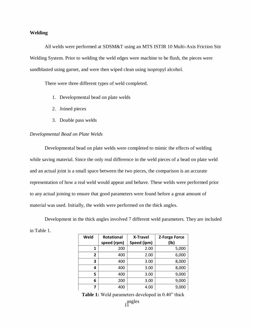
Development in the thick angles involved 7 different weld parameters. They are included
in Table 1.
Weld Rotational speed (rpm)
X-Travel Speed (ipm)
Z-Forge Force (lb)
1 200 2.00 5,000
2 400 2.00 6,000
3 400 3.00 8,000
4 400 3.00 8,000
5 400 3.00 9,000
6 200 3.00 9,000
7 400 4.00 9,000
Table 1: Weld parameters developed in 0.40” thick
angles
12
Samples were evaluated using metallographic techniques and microhardness testing.
Specifics on the procedures for these tests will be included in the section titled “Microstructural
Analysis.”
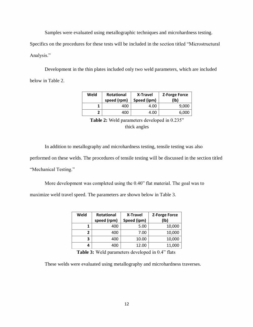
Development in the thin plates included only two weld parameters, which are included
below in Table 2.
Weld Rotational speed (rpm)
X-Travel Speed (ipm)
Z-Forge Force (lb)
1 400 4.00 9,000
2 400 4.00 6,000
In addition to metallography and microhardness testing, tensile testing was also
performed on these welds. The procedures of tensile testing will be discussed in the section titled
“Mechanical Testing.”
More development was completed using the 0.40” flat material. The goal was to
maximize weld travel speed. The parameters are shown below in Table 3.
These welds were evaluated using metallography and microhardness traverses.
Weld Rotational speed (rpm)
X-Travel Speed (ipm)
Z-Forge Force (lb)
1 400 5.00 10,000
2 400 7.00 10,000
3 400 10.00 10,000
4 400 12.00 11,000
Table 2: Weld parameters developed in 0.235”
thick angles
Table 3: Weld parameters developed in 0.4” flats
13
One developmental bead on plate double pass weld was also performed before actual
joining took place. Both passes were performed at 400 rpm, 5 ipm, and 10,000 lb forge force. It
was evaluated using metallography and microhardness traverses.
Joined Pieces
Pieces were joined in both the 0.235” and 0.4” thick flat plates.
In the 0.235” plates, material was welded at 4 ipm, 400 rpm and 6000 lb forge force. This
weld was saved as a demonstration piece as materials ran low.
In the 0.40” thick plates, double pass welds were completed and will be discussed in the
next section.
Double Pass Welds
Double pass welds were completed to achieve full penetration welds in plates that were
too thick for single penetration given the author’s available tools. The first weld pass was
completed using 400 rpm, 5 ipm and 10,000 lbs and penetrated 0.235” into the weld. After the
first pass was completed the weld piece was flipped over and the tool was lined up to run over
the exact path that the first weld traveled over. The 2nd
pass weld was run at the same parameters
as the first pass.
Heat Treatment
The material used in this research requires a stress relief step in the as rolled condition in
order to meet elongation requirements, and also requires a tempering step to soften martensite
after welding. It was decided to perform both of these steps post weld in order to save time and
energy. Every heat treatment mentioned in this paper involves placing the piece in the furnace at
1150°F, holding for two hours, and then allowing to air cool.
14
Microstructural Analysis
Microstructural analysis is performed by a combination of metallography and
microhardness testing.
Metallography
Metallography involves the polishing, etching, and observation of samples under an
optical microscope. All metallograhpic samples were polished to 1 µm and etched with 2% nital.
Samples were prepared for all weld conditions.
Microhardness Testing
Microhardness testing was performed to confirm results found through
metallography, as different phases of steel exhibit unique hardnesses. Also, weld traverses are
completed to examine how far the HAZ/TMAZ extends into the parent material. This
information is important because the HAZ/TMAZ is the region of a weld most likely to fail first.
Hardness testing also reveals whether or not post weld heat treatment will be a requirement
because a very hard weld is likely to be brittle and in need of tempering and stress relief.
Microhardness tests were performed on a Vickers microhardness tester. All
microhardness samples were polished to 1 µm. Traverses were completed starting in the parent
material on one side of the weld, travelling inwards towards the HAZ/TMAZ region, through the
weld nugget, and then out the other side. For double sided welds, traverses were also completed
starting in the 2nd
pass weld and going downwards through the region of overlap between the
weld passes and into the 1st pass until the bottom of the plate was reached. Distance between
indents and number of indents varied for each sample.
15
Mechanical Testing
Mechanical testing involved only tensile testing. Samples were cut out using a water jet
cutter and testing was performed according to ASTM standard E8. Bead on plate welds
performed in the 0.40” thick material were machined to mimic a full penetration weld. Special
attention was given to the zones in which material failed in.
At the time of this writing, samples for fatigue testing were sent out but no data has been
received yet.
Results
Microstructural Analysis
The results of microstructural analysis are included below and include data for parent
material, the weld nugget, the HAZ/TMAZ, and for double sided welds. Emphasis was placed on
comparing the starting microstructures and the microstructural evolutions of the angled material
and flat plates.
Metallography
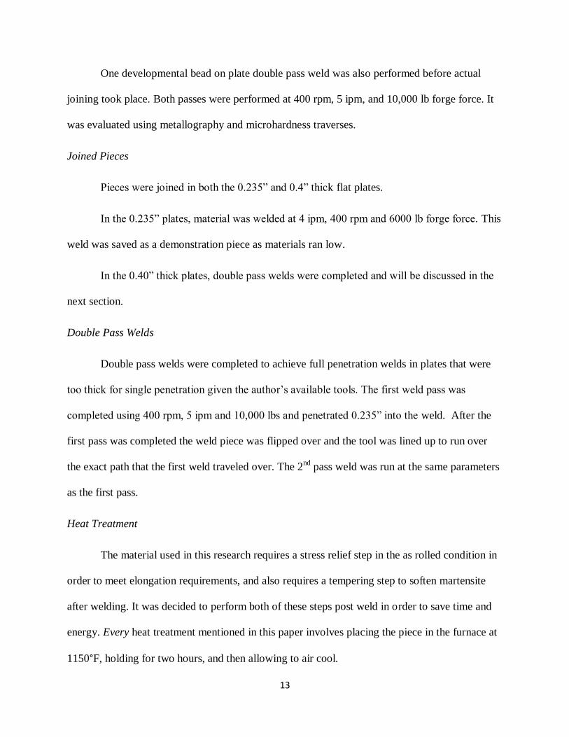
A reference image is provided below in Figure 3 for comparison. It shows a macro image
of the different regions of weld material that will be discussed in this section.
Figure 3: Bead on plate weld with
different weld zones labeled.
Zone A: Unaffected parent material
Zone B: HAZ/TMAZ
Zone C: Weld nugget/stir zone
16
Parent Material
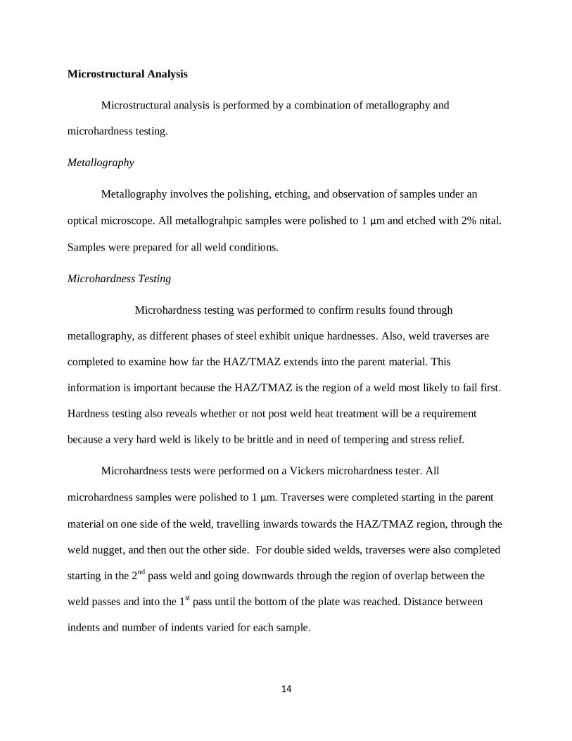
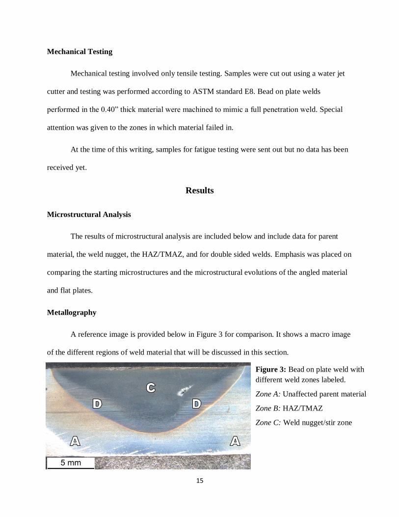
The microstructure of the angled material to be used in production is a mix of ferrite and
pearlite. Large non-metallic inclusions are very prevalent in the steel’s microstructure. However,
the developmental flat plates rolled show a microstructure comprised completely of acicular
ferrite. This discrepancy can be attributed to faster post hot rolling cooling rates experienced by
the flats to the angles as a result of the difference in geometry. The difference can be seen below
in Figures 4 and 5.
The ferrite formed in the angled material is also acicular in appearance as opposed to
granular. The acicular shape is the result of the numerous non-metallic inclusions present in the
metal. Instead of bainite forming in and along the austenite grain boundaries, lenticular shaped
ferrite grains branch off of these inclusions as temperatures fall below the austenite
transformation temperature, forming the acicular pattern seen in the images above.
Figure 4: Microstructure of the angled material to
be used in production. White areas are colonies of
ferrite, darker areas are pearlite. Dark inclusions can
be seen.
Figure 5: Microstructure of flats rolled to mimic
welded portion of the angle material. The structure
is completely acicular ferrite.

17
Average grain size measurements in the angles were found to be close to ASTM grain
size 8.1. In the flats, it was simply noted that the acicular grains are very fine.
Weld Nugget
It is important to compare the microstructure of welded material to parent material to
determine if the difference in starting microstructure will have an effect on the performance of
the developmental product. Weld nugget microstructure is the same in both the angled and flat
plates. Both consist of an acicular pattern consistent with martensite. Because there is no
observable difference in images taken of the weld nuggets, only one image of a weld nugget is
included below in Figure 6.
Martensite formation in the weld nugget indicates that temperatures exceed austenitizing
range and have the rapid cooling rates required for martensite formation. Temperature data
obtained by thermocouple readings on the weld piece confirm that material along the joint is in
Figure 6: Weld nugget microstructure comprised of
martensite. Sample was welded at 10 ipm in the flat
plates. Dark inclusions are still present.
18
excess of 800°C, sufficient for the austenite formation that allows for martensitic transformation.
The large steel anvil on the MTS ISTIR 10 was not heated and acted as a heat sink for the weld
pieces, causing the rapid quenching conditions necessary for martensitic transformation to occur.
Deeper characterization of the martensite was largely unsuccessful. The appearance of
martensite found indicates the presence of lath martensite as opposed to plate martensite, which
is to be expected from steel with this carbon content. Further characterization proved difficult, as
defining packet size is difficult for steels of this carbon content. Attempts to measure prior
austenite grain size was thwarted by difficulty in obtaining picric acid for picral etchant.
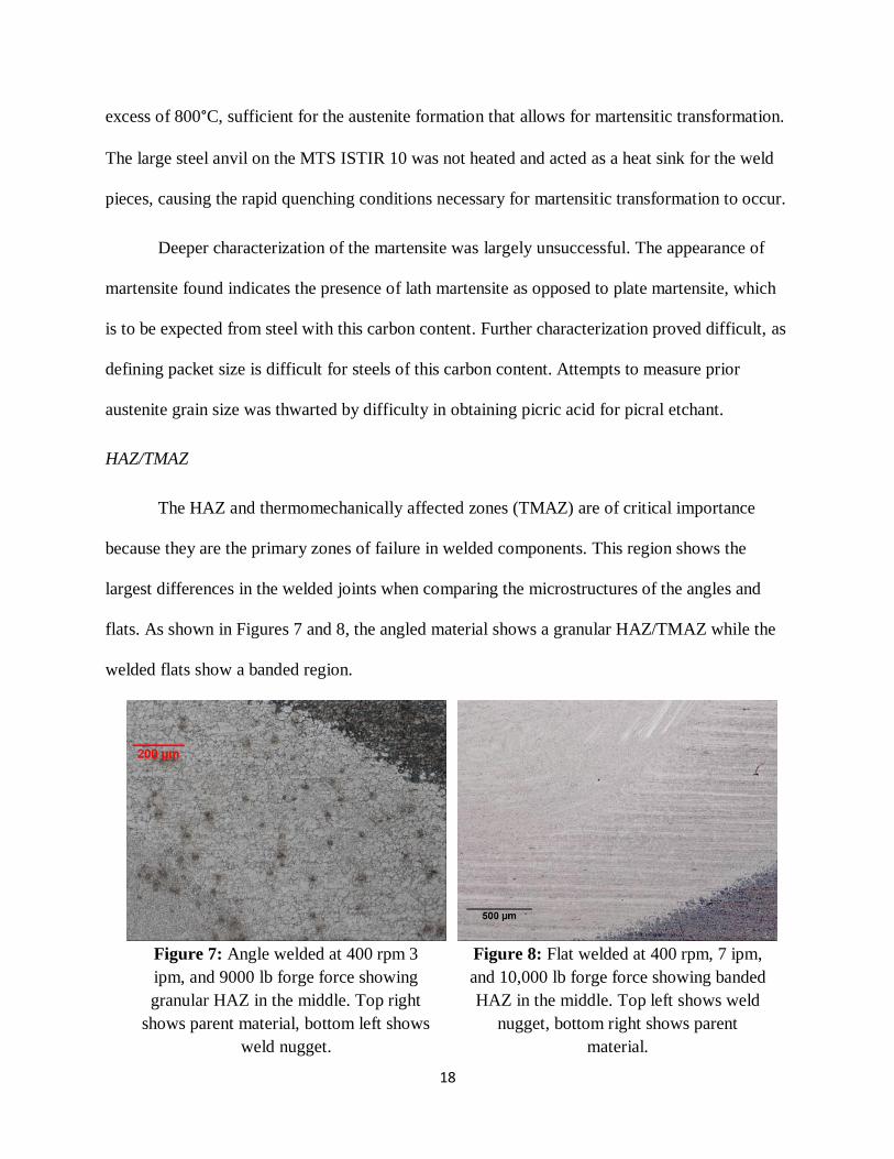
HAZ/TMAZ
The HAZ and thermomechanically affected zones (TMAZ) are of critical importance
because they are the primary zones of failure in welded components. This region shows the
largest differences in the welded joints when comparing the microstructures of the angles and
flats. As shown in Figures 7 and 8, the angled material shows a granular HAZ/TMAZ while the
welded flats show a banded region.
Figure 8: Flat welded at 400 rpm, 7 ipm,
and 10,000 lb forge force showing banded
HAZ in the middle. Top left shows weld
nugget, bottom right shows parent
material.
Figure 7: Angle welded at 400 rpm 3
ipm, and 9000 lb forge force showing
granular HAZ in the middle. Top right
shows parent material, bottom left shows
weld nugget.

19
In the angles, grain size is only slightly larger in the HAZ/TMAZ in comparison with the
parent material. As shown below in Figures 9 and 10, one sample welded at 400 rpm, 2 ipm
travel speed and 6000 lb forge force saw a decrease in grain size number from 8.1 to 7.8.
Since HAZ size directly impacts the performance of the weld, the size of the HAZ as a
function of heat input was examined. As expected, welds produced with colder parameters have
a narrower HAZ and hotter welds have a broader HAZ. Figure 10 on the next page shows
relative HAZ size changing as a result of higher heat input. Rotational speed was held constant at
400 rpm, but travel speeds and forge force was varied. HAZ size generally decreased as travel
speed was increased, except in the case of the sample welded at 12 ipm. The 12 ipm sample had
a higher forge force and because of the high normal force applied by the tool, frictional heat
generated by the rubbing of the shoulder of the tool on the surface of the plates was higher and
therefore left a larger HAZ.
Figure 9: Grain size measurements in
unaffected parent material of welded sample.
Figure 10: Grain size measurements in HAZ
of welded sample.

20
Because of the larger HAZ obtained from hotter welds, colder welds are preferred in the
FSW of steel so long as they do not produce defects. However, the trials performed at the highest
travel speeds of 10 and 12 ipm produced defects typically observed in cold welds. The primary
defect observed was scalloping, or periodic void formation. These voids were found on the
advancing side of the welds and can be seen below in Figures 11 and 12 in both from the front
and side of the weld.
Relative
HAZ Size
Travel Speed
Figure 10: Decreasing HAZ size as a result of lower heat input in faster welds.
Figure 11: Void in sample welded at 12 ipm
seen from the front of the weld.
Figure 12: Perioidic voids in sample welded at
12 ipm seen from the side of the weld.
5 ipm
7 ipm
10 ipm
12 ipm

21
Double Pass Welds
At the time of this writing, the author did not have a tool capable of completing full
penetration welds in the 0.40” thick plates in a single pass, so it was elected to first attempt a
double pass weld. A cross sectional image of this type of weld is shown below in Figure 13.
The first pass weld was in effect heat treated by the second pass weld. The martensitic
structure of the 1st pass weld was tempered and became a tempered martensite. The 2
nd pass weld
appeared identical to a regular bead on plate weld except in the areas of overlap with the 1st pass.
Figure 13: Cross sectional view of a double pass bead on plate weld. The 1st pass weld is the
darker bowl shape at the bottom of the image, and the 2nd
pass is the more colorful bowl
shape on the top of the image.

22
A unique stir pattern was found here but, as will be explained later, it was not found to play any
significant role in the behavior of the material.
Void defects, such as the one below in Figure 15, were found in the latter portions of the
welds where the heat input was highest. As the weld travels closer to the end of a plate, heat has
less room to disperse and “bottles up” in the material, creating a hotter weld condition and larger
HAZ. It is not generally expected to see void defects in hot welds, as they are more prevalent in
colder welds where the material is not as plastic. In this case, however, a great amount of
material was lost to flashing and it is thought that enough material was removed from the weld
so that the process did not have enough material to fully consolidate. More data is needed to
confirm this hypothesis, though.
Figure 15: Defect, boxed in red, found near the end of a double pass weld. Note the
large HAZ when compared to Figure 13.
23
Average 342.9
Max 366.8
Min 277.4
Std Dev 27.6
Angled Material
Average 309.2
Max 362.7
Min 234.9
Std Dev 25.5
0.40" Flats
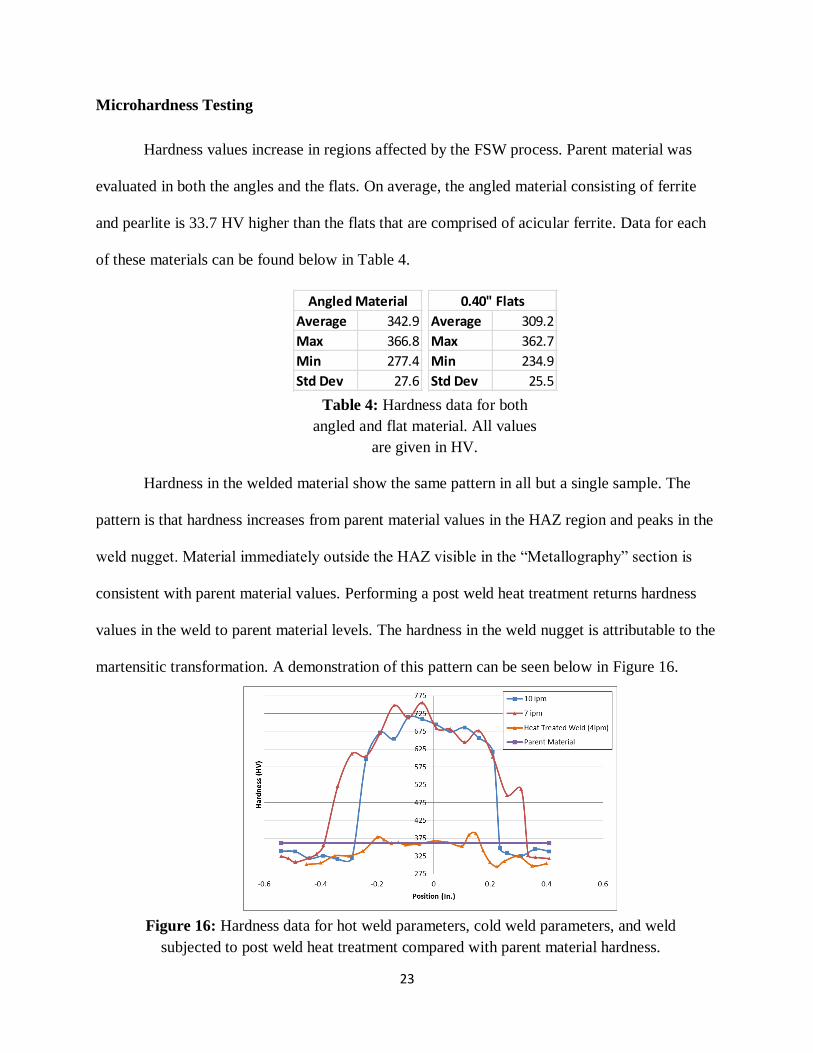
Microhardness Testing
Hardness values increase in regions affected by the FSW process. Parent material was
evaluated in both the angles and the flats. On average, the angled material consisting of ferrite
and pearlite is 33.7 HV higher than the flats that are comprised of acicular ferrite. Data for each
of these materials can be found below in Table 4.
Hardness in the welded material show the same pattern in all but a single sample. The
pattern is that hardness increases from parent material values in the HAZ region and peaks in the
weld nugget. Material immediately outside the HAZ visible in the “Metallography” section is
consistent with parent material values. Performing a post weld heat treatment returns hardness
values in the weld to parent material levels. The hardness in the weld nugget is attributable to the
martensitic transformation. A demonstration of this pattern can be seen below in Figure 16.
Table 4: Hardness data for both
angled and flat material. All values
are given in HV.
Figure 16: Hardness data for hot weld parameters, cold weld parameters, and weld
subjected to post weld heat treatment compared with parent material hardness.

24
Note that because the weld in blue had a faster travel speed, it has a more narrow HAZ
region than the 7 ipm sample. HAZ hardness is generally between 450 and 600 HV. Though the
peak hardness value appears in the 7 ipm sample, heat input does not appear to affect peak
hardness directly. Weld nugget hardness is generally between 650 and 750 HV. Because peak
hardness remains fairly constant throughout all weld parameters, and because metallographic
analysis shows no evidence to the contrary, it can be concluded that the weld nugget undergoes
100% martensitic transformation.
The one sample that deviated from these results had a much lower heat input than the
other samples. It is listed as Weld 1 in Table 1 and its weld parameters were 200 rpm, 2 ipm, and
5,000 lb forge force. Peak hardness in this sample is only 634.9 HV and average weld nugget
hardness is 590.8 HV. It can be concluded from this information that this particular weld did not
undergo complete martensitic transformation, confirming results from previous studies regarding
sub-critical temperature welding. More metallographic analysis is required to ascertain other
phases present in the weld nugget.
Double pass welds have unique hardness profiles because the second pass weld heat
treats the first pass. However, results are still fairly consistent with the findings listed above. The
2nd
pass weld has a hardness profile identical to that of a normal weld. The 1st pass weld acts the
same as a weld subjected to post weld heat treatment. Hardness profiles are shown below in
Figures 17 and 18.

25
Figure 17: Horizontal hardness profile of a double pass weld.
Figure 18: Vertical hardness profile of a double pass weld.
26
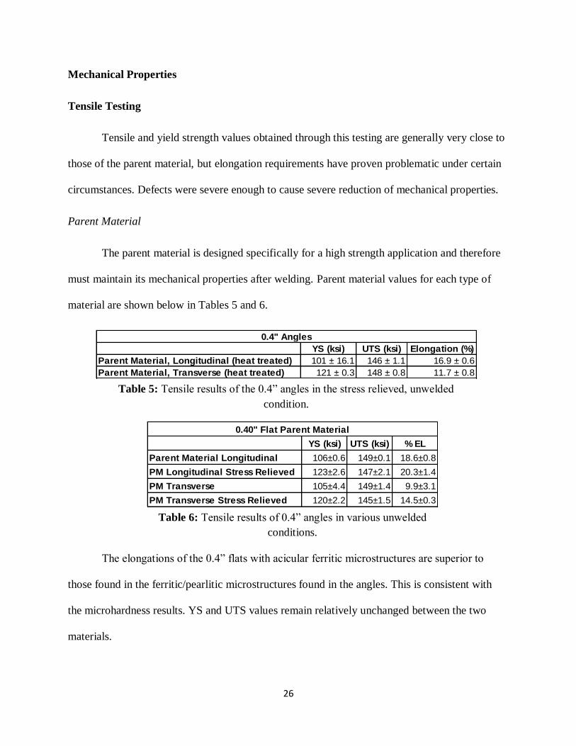
YS (ksi) UTS (ksi) Elongation (%)
Parent Material, Longitudinal (heat treated) 101 ± 16.1 146 ± 1.1 16.9 ± 0.6
Parent Material, Transverse (heat treated) 121 ± 0.3 148 ± 0.8 11.7 ± 0.8
0.4" Angles
YS (ksi) UTS (ksi) % EL
Parent Material Longitudinal 106±0.6 149±0.1 18.6±0.8
PM Longitudinal Stress Relieved 123±2.6 147±2.1 20.3±1.4
PM Transverse 105±4.4 149±1.4 9.9±3.1
PM Transverse Stress Relieved 120±2.2 145±1.5 14.5±0.3
0.40" Flat Parent Material
Mechanical Properties
Tensile Testing
Tensile and yield strength values obtained through this testing are generally very close to
those of the parent material, but elongation requirements have proven problematic under certain
circumstances. Defects were severe enough to cause severe reduction of mechanical properties.
Parent Material
The parent material is designed specifically for a high strength application and therefore
must maintain its mechanical properties after welding. Parent material values for each type of
material are shown below in Tables 5 and 6.
The elongations of the 0.4” flats with acicular ferritic microstructures are superior to
those found in the ferritic/pearlitic microstructures found in the angles. This is consistent with
the microhardness results. YS and UTS values remain relatively unchanged between the two
materials.
Table 5: Tensile results of the 0.4” angles in the stress relieved, unwelded
condition.
Table 6: Tensile results of 0.4” angles in various unwelded
conditions.
27
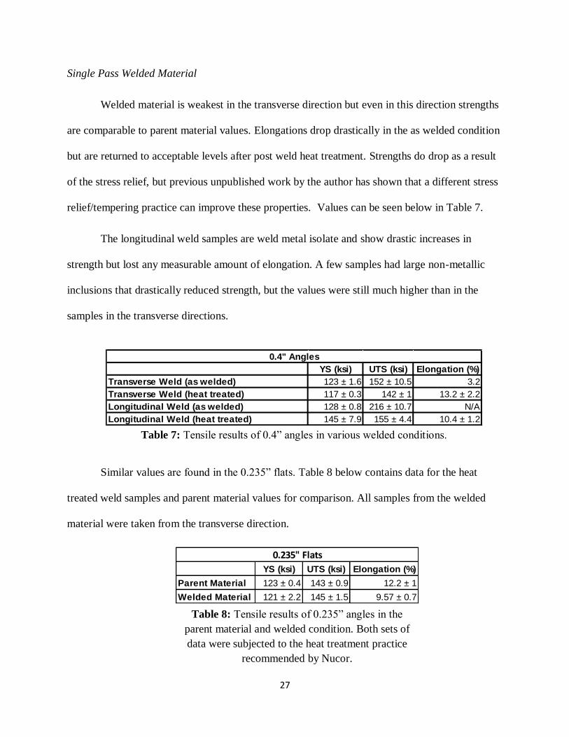
YS (ksi) UTS (ksi) Elongation (%)
Transverse Weld (as welded) 123 ± 1.6 152 ± 10.5 3.2
Transverse Weld (heat treated) 117 ± 0.3 142 ± 1 13.2 ± 2.2
Longitudinal Weld (as welded) 128 ± 0.8 216 ± 10.7 N/A
Longitudinal Weld (heat treated) 145 ± 7.9 155 ± 4.4 10.4 ± 1.2
0.4" Angles
YS (ksi) UTS (ksi) Elongation (%)
Parent Material 123 ± 0.4 143 ± 0.9 12.2 ± 1
Welded Material 121 ± 2.2 145 ± 1.5 9.57 ± 0.7
0.235" Flats
Single Pass Welded Material
Welded material is weakest in the transverse direction but even in this direction strengths
are comparable to parent material values. Elongations drop drastically in the as welded condition
but are returned to acceptable levels after post weld heat treatment. Strengths do drop as a result
of the stress relief, but previous unpublished work by the author has shown that a different stress
relief/tempering practice can improve these properties. Values can be seen below in Table 7.
The longitudinal weld samples are weld metal isolate and show drastic increases in
strength but lost any measurable amount of elongation. A few samples had large non-metallic
inclusions that drastically reduced strength, but the values were still much higher than in the
samples in the transverse directions.
Similar values are found in the 0.235” flats. Table 8 below contains data for the heat
treated weld samples and parent material values for comparison. All samples from the welded
material were taken from the transverse direction.
Table 7: Tensile results of 0.4” angles in various welded conditions.
Table 8: Tensile results of 0.235” angles in the
parent material and welded condition. Both sets of
data were subjected to the heat treatment practice
recommended by Nucor.
28
YS (ksi) UTS (ksi) % EL
As Welded (with defect) 126±2.9 145±17 2.1±1.3
As Welded (without defect) 126±2.9 153±8.6 2.2±1.6
Welded & Tempered 131±3.3 149±3.1 4.9±2.5
Double Pass Bead on Plate Weld
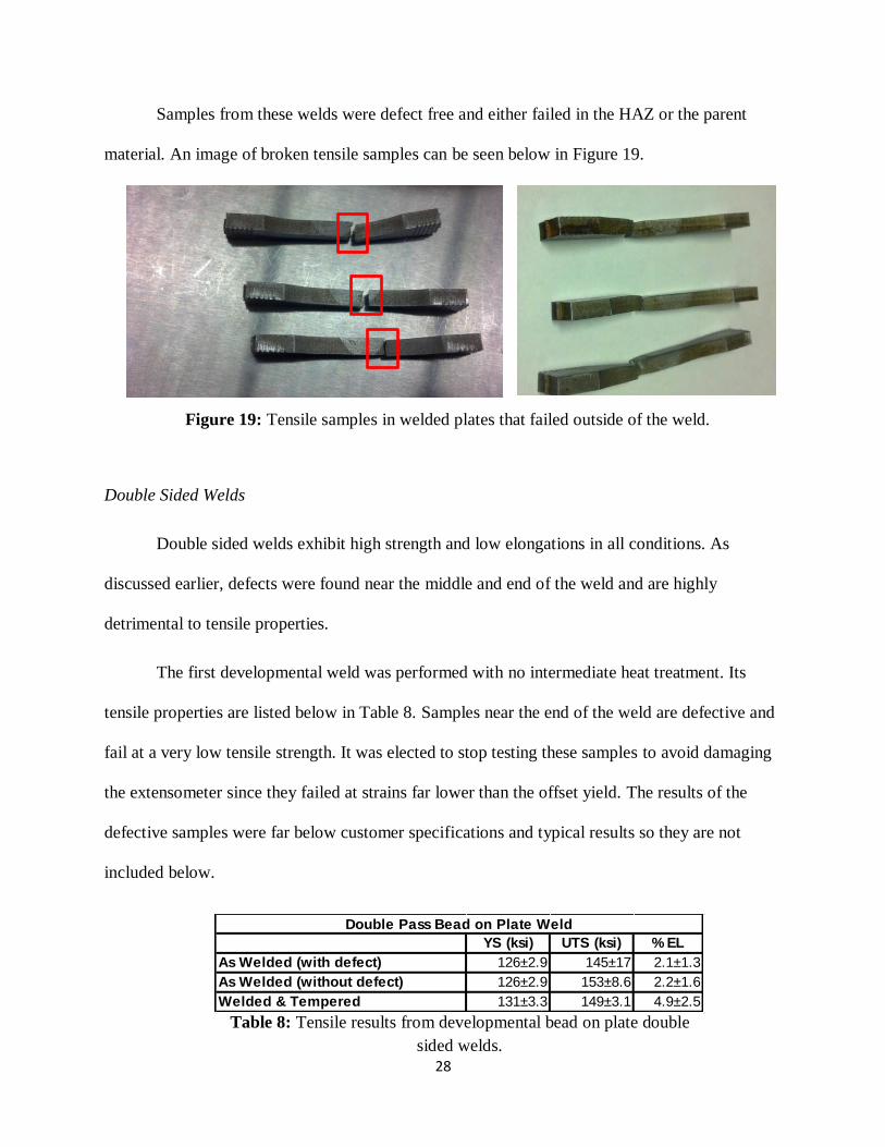
Samples from these welds were defect free and either failed in the HAZ or the parent
material. An image of broken tensile samples can be seen below in Figure 19.
Double Sided Welds
Double sided welds exhibit high strength and low elongations in all conditions. As
discussed earlier, defects were found near the middle and end of the weld and are highly
detrimental to tensile properties.
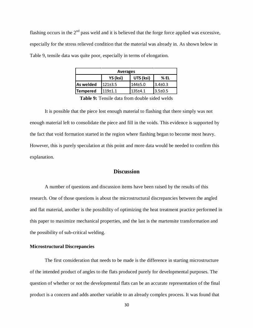
The first developmental weld was performed with no intermediate heat treatment. Its
tensile properties are listed below in Table 8. Samples near the end of the weld are defective and
fail at a very low tensile strength. It was elected to stop testing these samples to avoid damaging
the extensometer since they failed at strains far lower than the offset yield. The results of the
defective samples were far below customer specifications and typical results so they are not
included below.
Figure 19: Tensile samples in welded plates that failed outside of the weld.
Table 8: Tensile results from developmental bead on plate double
sided welds.
29
There is a large standard deviation in elongation results, but one sample was able to
obtain an elongation of nearly 7%. Though not up to customer specifications, this result is
promising and it is believed that with some parameter development these specifications can be
met.
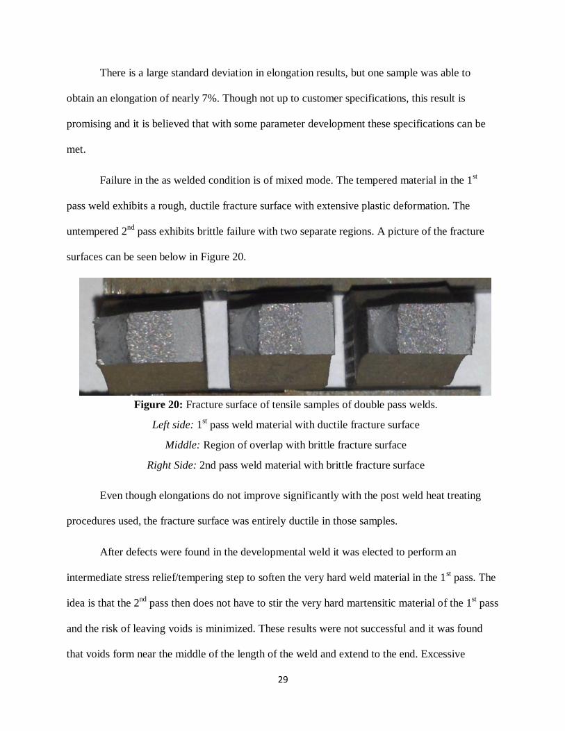
Failure in the as welded condition is of mixed mode. The tempered material in the 1st
pass weld exhibits a rough, ductile fracture surface with extensive plastic deformation. The
untempered 2nd
pass exhibits brittle failure with two separate regions. A picture of the fracture
surfaces can be seen below in Figure 20.
Even though elongations do not improve significantly with the post weld heat treating
procedures used, the fracture surface was entirely ductile in those samples.
After defects were found in the developmental weld it was elected to perform an
intermediate stress relief/tempering step to soften the very hard weld material in the 1st pass. The
idea is that the 2nd
pass then does not have to stir the very hard martensitic material of the 1st pass
and the risk of leaving voids is minimized. These results were not successful and it was found
that voids form near the middle of the length of the weld and extend to the end. Excessive
Figure 20: Fracture surface of tensile samples of double pass welds.
Left side: 1st pass weld material with ductile fracture surface
Middle: Region of overlap with brittle fracture surface
Right Side: 2nd pass weld material with brittle fracture surface
30
YS (ksi) UTS (ksi) % EL
As welded 121±3.5 144±5.0 3.4±0.3
Tempered 119±1.1 135±4.1 3.5±0.5
Averages
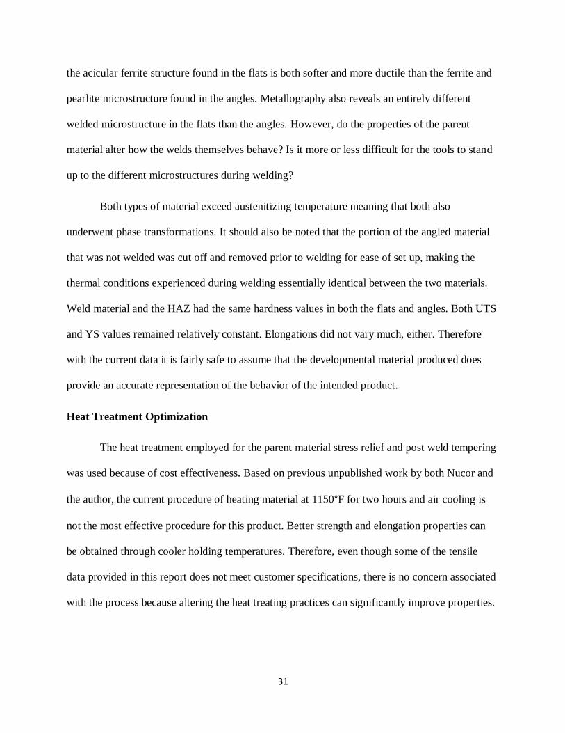
flashing occurs in the 2nd
pass weld and it is believed that the forge force applied was excessive,
especially for the stress relieved condition that the material was already in. As shown below in
Table 9, tensile data was quite poor, especially in terms of elongation.
It is possible that the piece lost enough material to flashing that there simply was not
enough material left to consolidate the piece and fill in the voids. This evidence is supported by
the fact that void formation started in the region where flashing began to become most heavy.
However, this is purely speculation at this point and more data would be needed to confirm this
explanation.
Discussion
A number of questions and discussion items have been raised by the results of this
research. One of those questions is about the microstructural discrepancies between the angled
and flat material, another is the possibility of optimizing the heat treatment practice performed in
this paper to maximize mechanical properties, and the last is the martensite transformation and
the possibility of sub-critical welding.
Microstructural Discrepancies
The first consideration that needs to be made is the difference in starting microstructure
of the intended product of angles to the flats produced purely for developmental purposes. The
question of whether or not the developmental flats can be an accurate representation of the final
product is a concern and adds another variable to an already complex process. It was found that
Table 9: Tensile data from double sided welds
31
the acicular ferrite structure found in the flats is both softer and more ductile than the ferrite and
pearlite microstructure found in the angles. Metallography also reveals an entirely different
welded microstructure in the flats than the angles. However, do the properties of the parent
material alter how the welds themselves behave? Is it more or less difficult for the tools to stand
up to the different microstructures during welding?
Both types of material exceed austenitizing temperature meaning that both also
underwent phase transformations. It should also be noted that the portion of the angled material
that was not welded was cut off and removed prior to welding for ease of set up, making the
thermal conditions experienced during welding essentially identical between the two materials.
Weld material and the HAZ had the same hardness values in both the flats and angles. Both UTS
and YS values remained relatively constant. Elongations did not vary much, either. Therefore
with the current data it is fairly safe to assume that the developmental material produced does
provide an accurate representation of the behavior of the intended product.
Heat Treatment Optimization
The heat treatment employed for the parent material stress relief and post weld tempering
was used because of cost effectiveness. Based on previous unpublished work by both Nucor and
the author, the current procedure of heating material at 1150°F for two hours and air cooling is
not the most effective procedure for this product. Better strength and elongation properties can
be obtained through cooler holding temperatures. Therefore, even though some of the tensile
data provided in this report does not meet customer specifications, there is no concern associated
with the process because altering the heat treating practices can significantly improve properties.
32
Martensite Phase Transformation and Sub-Critical Welding
The martensite transformation that occurs as a result of welding can be detrimental to
physical properties because of the brittle behavior and subsequent lack of toughness exhibited by
martensite, however it is not unique to the FSW process. Other welding methods have a much
greater heat input than FSW and can also form martensite. There are also ways to avoid this
transformation entirely. Work by Fuji has shown that welding done with the correct parameters
can avoid exceeding austenitizing temperature all together, eliminating the possibility of this
phase transformation. The methods developed in his paper are very slow, however, and would be
unlikely to be used in a production setting. The materials used were also far thinner and not as
strong as the material used in this research, and since plastic deformation provides much of the
heat generated in FSW, temperatures were undoubtedly lower in that study than this one. More
feasible is reducing the cooling rate to slow enough so that the quenching conditions for
martensite cannot occur. This can be accomplished through welding on a hot anvil or by using
induction heating. This eliminates the need for any post weld heat treatment to relieve brittle
behavior caused by phase transformations in all types of steel.
Conclusion
Summary
With the correct weld parameters, FSW can be an effective joining practice even for
ultra-high strength steels such as the one used in this paper. Defect free welds with mechanical
properties approaching, and sometimes even improving, those of the parent material have been
developed. So far, however, there is still a great deal of development required for it to be an
effective production practice. Martensitic transformation is still a large consideration to consider
33
when using FSW on steel, but its effects can be circumvented through proper post weld heat
treatment or cooling rate control. The following conclusions can be made:
1. The acicular ferrite found in the flat plates provides an accurate developmental
comparison to the ferrite and pearlite microstructure found in the angles actually
planned to be used in production.
2. The high temperatures and rapid cooling of the material during welding leads to a
martensitic transformation in the weld nugget.
3. Hardness in both the weld nugget and HAZ/TMAZ is very high in the as welded
condition, leading to decreased ductility and brittle weld behavior. Post weld heat
treatment is required to relieve stresses and temper the martensite if no action is
taken to prevent martensite transformation.
4. Post weld heat treatment can restore hardness and ductility to acceptable levels.
5. It is difficult to perform FSW without exceeding austenitizing temperature.
Therefore, preventing martensitic transformation is more likely to be
accomplished by slowing cooling rates through induction heating or some other
method.
6. Material is refined in the weld nugget as a result of forging, drastically improving
mechanical properties in the weld metal itself.
7. Tensile properties of the welded material are very close to those of the parent
material, though elongation does not always meet minimum customer
specifications. A better heat treatment practice can be developed so that the
material will meet these specifications.
34
8. Double sided welds can be performed but more weld parameter development is
required for them to be effective. There are also more efficient possibilities to be
used than the procedures used in this paper.
9. No tool wear was observed in any weld trials, but inspection was purely visual
and no quantitative results have been obtained.
Recommendations
The author recommends the following solutions to further improve weld properties and
production feasibility:
1. Perform post weld heat treatment at a lower temperature. Cooler heat treatments for this
material have proven more effective for Nucor in the past and could provide an easy and
immediate upgrade to all current weld parameters as well as future ones.
2. Use a tool with a more featured surface than the smooth one currently used. The features
will be more suitable for the grabbing and transporting of weld metal during the process,
especially in cooler welds. These tools can potentially eliminate the problems with voids
experienced in the welds with faster travel speeds and the double sided welds.
3. Perform welds at sub-critical cooling rates to avoid the martensitic phase transformation.
This particular material requires a stress relief step even in the as rolled condition, but
the ability to weld without brittle phase transformation can be massively useful to this
and other steel joining applications.
4. Perform welds in the 0.4” material with lower forge force. The material experienced
excessive flashing and a wider HAZ when high forge force was applied. A lower forge
force could eliminate post weld clean up, material loss, and can help to narrow the HAZ.
35
5. Obtain a larger tool for single pass welds in the 0.4” thick material or perform a self-
reacting weld in which two tools weld the plates simultaneously. Both properties and
efficiency would improve with these methods.
Future Work
Though FSW of steel has come a long way, a great deal of development is still required
before it can be an effective production practice. Steps to be taken in the future include the
following:
1. Further parameter development that involves pushing the process envelope to maximize
production efficiency using different tool materials and geometries.
2. Fatigue testing.
3. Single pass welds in 0.40” thick material using larger tools or performing self-reacting
welds.
4. Sub critical welding using induction heating, heated anvils, or even welding in a cooled
atmosphere to prevent reaching austenitization temperature so that martensite does not
form in the weld.
5. Quantitative tool wear studies to help determine cost effectiveness and capabilities of
FSW in steel production.
6. Exploration of cost effective tool materials.

36
References
1. Ahn, B. W., Choi, D. H., Kim, D. J., & Jung, S. J. (2012). Microstructures and properties
of friction stir welded 409l stainless steel using a si3n4 tool. Materials Science and
Engineering, 532, 476-479. doi: 10.1016/j.msea.2011.10.109
2. Babu, S. S. (2004). The mechanism of acicular ferrite in weld deposits. Current Opinion
in Solid State and Materials Science, 8, 267-278. doi: 10.1016/j.cossms.2004.10.001
3. Baek, S., Choi, D., Lee, C., Ahn, B., Yeon, Y., Song, K., & Jung, S. (2010). Structure-
properties relations in friction stir spot welded low carbon steel sheets for light weight
automobile body. Materials Transactions, 51(2), 399-403.
4. Barnes, S. J., Bhatti, A. R., Steuwer, A., Johnson, R., Altenkirch, J., & Withers, P. J.
(2012). Friction stir welding in hsla-65 steel: Part i. influence of weld speed and tool
material on microstructural development. Metallurgical and Materials Transactions, 43A,
2342-2356. doi: 10.1007/s11661-012-1110-z
5. Chao, Y. J. (2002). Failure mode of spot welds: Interfacial versus pullout. Science of
Welding and Joining, 8(2), 133-137.
6. Choi, D. H., Ahn, B. W., Yeon, Y. M., Park, S. H., Sato, Y. S., Kokawa, H., & Jung, S.
B. (2011). Microstructural characterizations following friction stir welding of dissimilar
alloys of low- and high-carbon steels. Materials Transactions, 52(7), 1500-1505. doi:
10.2320/matertrans.M2010438]
7. Chung, Y. D., Fujii, H., Nakata , K., & Nogi, K. (2009). Friction stir welding of high
carbon tool steel (sk85) below eutectoid temperature. Transactions of JWRI, 38(1), 37-
42.
8. Feng, Z., Santella, M. L., David, S. A., Steel, R. J., Packer, S. M., Pan, T., Kuo, M.,
&Bhatnagar, R. S. (2005). Friction stir spot welding of advanced high-strength steels - a
feasibility study. Retrieved from
http://www.ornl.gov/~webworks/cppr/y2001/pres/122418.pdf
9. Fujii, H., Cui, L., Nakata, K., & Nogi, K. (2008). Mechanical properties of friction stir
welded carbon steel joints – friction stir welding with and without transformation.
Welding in the World, 52(9/10), 75-82.
10. Ghosh, M., Kumar, K., & Mishra, R. S. (2011). Friction stir lap welded advanced high
strength steels: Microstructure and mechanical properties. Material Science and
Engineering, 528, 8111-8119. doi: 10.1016/j.msea.2011.06.087
11. He, K., & Edmonds, D. V. (2002). Formation of acicular ferrite and influence of
vanadium alloying. Materials Science and Technology, 18, 289-297. doi:
10.1179/026708301225000743
37
12. Hovanski, Y., Santella, M. L., & Grant, G. J. (2007). Friction stir spot welding of hot-
stamped boron steel. Scripta Materiala, 57, 873-876. doi:
10.1016/j.scriptamat.2007.06.060
13. Huang, T., Sato, Y. S., Kokawa, H., Miles, M. P., Kohkonen, K., Siemssen, B., Steel, R.
J., & Packer, S. (2009). Microstructural evolution of dp980 steel during friction bit
joining. Metallurgical and Materials Transactions, 40A, 2994-3001. doi: 10.1007/s11661-
009-0016-x
14. Krauss, G. (2005). Steels: Processing, structure, and performance. Materials Park: ASM
International.
15. Keeler, S. (2009, June). Advanced high strength steel (AHSS) application guidelines.
16. Khan, M. I., Kuntz, M. L., Su, P., Gerlich, A., North, T., & Zhou, Y. (2007). Resistance
and friction stir spot welding of dp600: a comparative study. Science and Technology of
Welding and Joining, 12(2), 175-184. doi: 10.1179/174329307X159801
17. Kren, L. (2011, August 08). Developments in making gigapascal-strength steels.
18. Leonhardt, T. (2009). Properties of tungsten-rhenium and tungsten-rhenium with hafnium
carbide. JOM, 61(7), 68-72.
19. McPherson, N. A., Galloway, A. M., Cater, S. R., & Hambling, S. J. (2013). Friction stir
welding of thin dh36 steel plate. Science and Technology of Welding and Joining, 18(5),
441-451. doi: 10.1179/1362171813Y.0000000122
20. McPherson, N. A., Galloway, A. M., Wood, J., & Carter, S. R. (n.d.). A comparison
between single sided friction stir welded and submerged arc welded dh36 thin steel plate.
21. Miles, M. P., Hartman, T., Cunningham, C., Saunders, N., & Hovanski, Y. (n.d.). High
speed friction stir spot welding of advanced high strength steel. 299-307.
22. Miles, M. P., Ridges, C. S., Hovanski, Y., Peterson, J., Santella, M. L., & Steel, R.
(2011). Impact of tool wear on joint strength in friction stir spot welding of dp 980
steel. Science and Technology of Welding and Joining, 16(7), 642-649. doi:
10.1179/1362171811Y.0000000047
23. Ohashi, R. (2011). Henry granjon prize competition 2010 winner category a: “joining and
fabrication technology” study on friction stir spot welding of dual-phase high-strength
steel sheets. Welding in the World, 55(9/10)
24. Ohashi, R., Fujimoto, M., Mironov, S., Sato, Y. S., & Kokowa, H. (2009). Friction stir
joining of high strength steel sheets for automotive. Welding in the World, 53(5/6), 23-
28.
38
25. Ohashi, R., Fujimoto, M., Mironov, S., Sato, Y. S., & Kokowa, H. (2009). Effect of
contamination on microstructure in friction stir spot welded dp590 steel. Effect of
contamination on microstructure in friction stir spot welded DP590 steel, 14(3), 221-229.
doi: 10.1179/136217108X388642
26. Rodelas, J., Mishra, R. S., Hilmas, G., & Yuan, W. (2009). Mechanical evaluation of
friction stir spot welded advanced high strength steels. Friction Stir Welding and
Processing, V, 171-180.
27. Santella, M., Hovanski, Y., & Pan, T. Y. (2012). Friction stir spot welding of advanced
high strength steel. SAE International, 5(2), 382-390.
28. Santella, M., Hovanski, Y., Frederick, A., Grant, G., & Dahl, M. (2010). Friction stir spot
welding of dp780 carbon steel. Science and Technology of Welding and Joining, 15(4),
271-280. doi: 10.1179/136217109X12518083193630
29. Sato, Y. S., Yamanoi, H., Kokawa, H., & Furuhara, T. (2008). Characteristics of
microstructure in ultrahigh carbon steel produced during friction stir welding.ISIJ
International, 48(1), 71-76.
30. Thompson, B., & Babu, S. S. (2010). Tool degradation characterization in the friction stir
welding of hard metals. Welding Journal, 89, 256-262.
39
Acknowledgments
Funding for this research was provided by the National Science Foundation. Thanks goes
to Maddie Kincaid and Jack Moehring for their help in research tasks, and to Dr. Alfred Boysen
for the unparalleled time and effort he puts into helping each of his students grow as
communicators. Thanks also goes to the staff at the Arbegast Materials Processing Lab at
SDSM&T including Todd Curtis, Kristopher Klus, Matthew Carriker, and David Christian. A
very special thanks goes to Dr. Michael West and Dr. Bharat Jasthi who were the primary
advisors for this project and without whom this project would not have been completed. Finally,
a great thanks goes to Cory Anthony of Nucor Steel, Utah, who made this project possible and
was a continued support throughout the entirety of the research.