The Effects of End Conditions on the Load Capacity of Cold ...
15
Missouri University of Science and Technology Missouri University of Science and Technology Scholars' Mine Scholars' Mine International Specialty Conference on Cold- Formed Steel Structures (2014) - 22nd International Specialty Conference on Cold-Formed Steel Structures Nov 5th, 12:00 AM - 12:00 AM The Effects of End Conditions on the Load Capacity of Cold- The Effects of End Conditions on the Load Capacity of Cold- Formed Steel Column Members of Lipped Channel Cross-Section Formed Steel Column Members of Lipped Channel Cross-Section with Perforations Subjected to Compression Loading with Perforations Subjected to Compression Loading Martin Macdonald Muditha P. Kulatunga Follow this and additional works at: https://scholarsmine.mst.edu/isccss Part of the Structural Engineering Commons Recommended Citation Recommended Citation Macdonald, Martin and Kulatunga, Muditha P., "The Effects of End Conditions on the Load Capacity of Cold-Formed Steel Column Members of Lipped Channel Cross-Section with Perforations Subjected to Compression Loading" (2014). International Specialty Conference on Cold-Formed Steel Structures. 2. https://scholarsmine.mst.edu/isccss/22iccfss/session02/2 This Article - Conference proceedings is brought to you for free and open access by Scholars' Mine. It has been accepted for inclusion in International Specialty Conference on Cold-Formed Steel Structures by an authorized administrator of Scholars' Mine. This work is protected by U. S. Copyright Law. Unauthorized use including reproduction for redistribution requires the permission of the copyright holder. For more information, please contact [email protected].
Transcript of The Effects of End Conditions on the Load Capacity of Cold ...

Missouri University of Science and Technology Missouri University of Science and Technology
Scholars' Mine Scholars' Mine
International Specialty Conference on Cold-Formed Steel Structures
(2014) - 22nd International Specialty Conference on Cold-Formed Steel Structures
Nov 5th, 12:00 AM - 12:00 AM
The Effects of End Conditions on the Load Capacity of Cold-The Effects of End Conditions on the Load Capacity of Cold-
Formed Steel Column Members of Lipped Channel Cross-Section Formed Steel Column Members of Lipped Channel Cross-Section
with Perforations Subjected to Compression Loading with Perforations Subjected to Compression Loading
Martin Macdonald
Muditha P. Kulatunga
Follow this and additional works at: https://scholarsmine.mst.edu/isccss
Part of the Structural Engineering Commons
Recommended Citation Recommended Citation Macdonald, Martin and Kulatunga, Muditha P., "The Effects of End Conditions on the Load Capacity of Cold-Formed Steel Column Members of Lipped Channel Cross-Section with Perforations Subjected to Compression Loading" (2014). International Specialty Conference on Cold-Formed Steel Structures. 2. https://scholarsmine.mst.edu/isccss/22iccfss/session02/2
This Article - Conference proceedings is brought to you for free and open access by Scholars' Mine. It has been accepted for inclusion in International Specialty Conference on Cold-Formed Steel Structures by an authorized administrator of Scholars' Mine. This work is protected by U. S. Copyright Law. Unauthorized use including reproduction for redistribution requires the permission of the copyright holder. For more information, please contact [email protected].

The Effects of End Conditions on the Load Capacity of Cold-
Formed Steel Column Members of Lipped Channel Cross-Section with Perforations Subjected to Compression Loading
Martin Macdonald1 Muditha P Kulatunga2
Abstract The effects of end boundary conditions on the compressive load carrying capacity of cold-formed lipped channel sections with perforations are investigated and discussed. Most structural cold-formed steel members are typically manufactured with perforations. These perforations are pre-cut to accommodate electrical, plumbing, and heating services and so on. Due to the size, shape, and position of perforations and end conditions, ultimate strength and elastic stiffness of a structural member can be varied. This paper describes the ultimate strength results obtained from numerical, experimental, and theoretical investigations for two types of end conditions namely, flat-end and fixed-fixed. The numerical results given have been obtained using the ANSYS FEA software package. An experimental study of the buckling behaviour of lipped channel columns of same cross-section, but with different perforation shapes and end conditions is reported and the findings from this are used to validate numerical results; good correlation was obtained both with ultimate strength and failure modes. Further, the study showed that there are similar ultimate load values for corresponding compression members under flat-end and fixed-fixed end conditions, and in general, more conservative estimates of design rule predictions: AISI Specification, British Standard - BS 5950 Part 5, and Eurocode 3. 1 Head of Department, School of Engineering & Built Environment, Glasgow Caledonian University, Cowcaddens Road, Glasgow, G4 0BA, UK 2 PhD Student, School of Engineering & Built Environment, Glasgow Caledonian University, Cowcaddens Road, Glasgow, G4 0BA, UK
Twenty-Second International Specialty Conference on Cold-Formed Steel Structures St. Louis, Missouri, USA, November 5 & 6, 2014
129
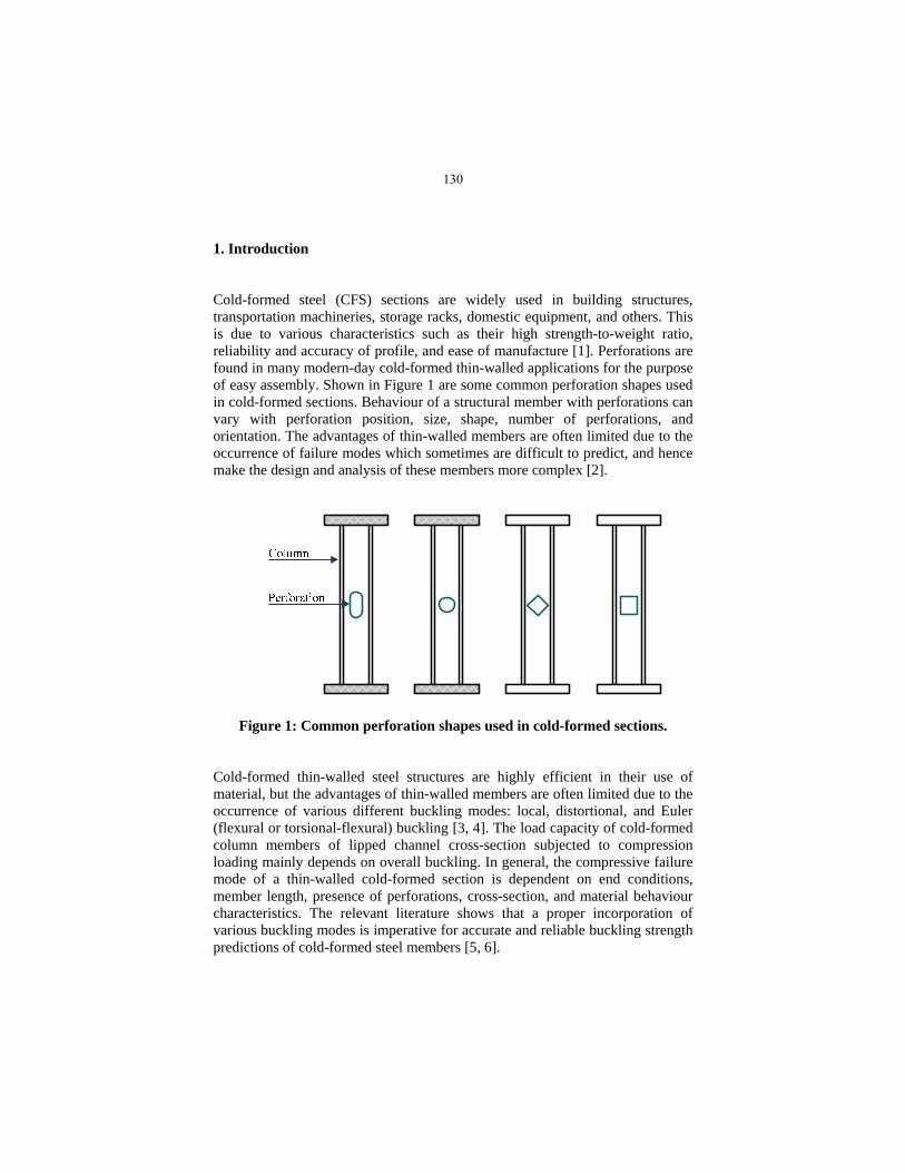
1. Introduction Cold-formed steel (CFS) sections are widely used in building structures, transportation machineries, storage racks, domestic equipment, and others. This is due to various characteristics such as their high strength-to-weight ratio, reliability and accuracy of profile, and ease of manufacture [1]. Perforations are found in many modern-day cold-formed thin-walled applications for the purpose of easy assembly. Shown in Figure 1 are some common perforation shapes used in cold-formed sections. Behaviour of a structural member with perforations can vary with perforation position, size, shape, number of perforations, and orientation. The advantages of thin-walled members are often limited due to the occurrence of failure modes which sometimes are difficult to predict, and hence make the design and analysis of these members more complex [2].
Figure 1: Common perforation shapes used in cold-formed sections.
Cold-formed thin-walled steel structures are highly efficient in their use of material, but the advantages of thin-walled members are often limited due to the occurrence of various different buckling modes: local, distortional, and Euler (flexural or torsional-flexural) buckling [3, 4]. The load capacity of cold-formed column members of lipped channel cross-section subjected to compression loading mainly depends on overall buckling. In general, the compressive failure mode of a thin-walled cold-formed section is dependent on end conditions, member length, presence of perforations, cross-section, and material behaviour characteristics. The relevant literature shows that a proper incorporation of various buckling modes is imperative for accurate and reliable buckling strength predictions of cold-formed steel members [5, 6].
130
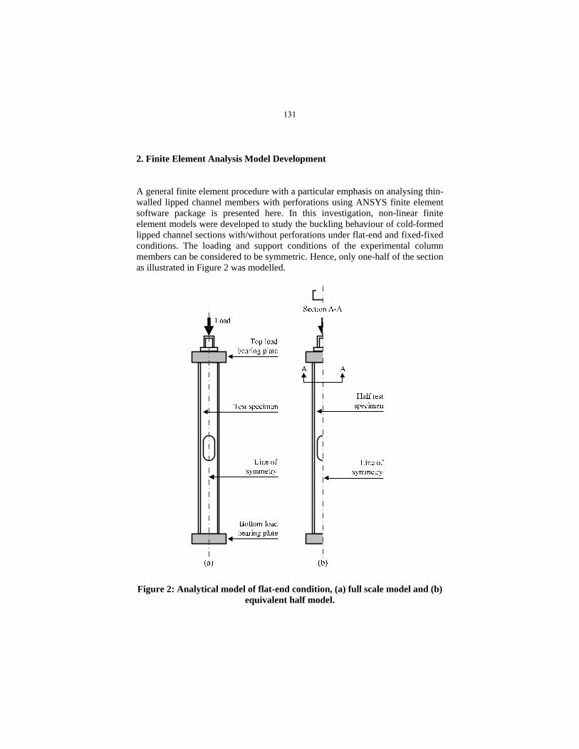
2. Finite Element Analysis Model Development A general finite element procedure with a particular emphasis on analysing thin-walled lipped channel members with perforations using ANSYS finite element software package is presented here. In this investigation, non-linear finite element models were developed to study the buckling behaviour of cold-formed lipped channel sections with/without perforations under flat-end and fixed-fixed conditions. The loading and support conditions of the experimental column members can be considered to be symmetric. Hence, only one-half of the section as illustrated in Figure 2 was modelled.
Figure 2: Analytical model of flat-end condition, (a) full scale model and (b) equivalent half model.
131

2.1 Finite Element Model Development for Flat-End and Fixed-Fixed Conditions The channel sections were modelled using shell element SHELL181 which is suitable for analysing thin to moderately-thick shell structures. The load was applied using load bearing plates which were modelled using solid element SOLID45 [7]. An adequate mesh density on contact surfaces and the section was provided to allow stresses to be distributed in a smooth fashion. A fine mesh was employed around perforations and coarse mesh further away from the perforations as shown in Figure 3 [8].
Figure 3: (a) Symmetry boundary and (b) mesh type, illustrating different regions of element mesh (fine and coarse).
132

Symmetric boundary conditions were applied at mid-section of the member. Y- (UY) direction displacement was fixed and the rotations about the X- (ROTX) axis and Z- (ROTZ) axis were also fixed. In flat-end supported conditions, one end of the column was restricted for three degrees of freedom and the other end was restricted for two degrees of freedom as illustrated in Figure 4.
Figure 4: Boundary conditions for flat-end condition.
In fixed-fixed supported conditions the nodes at the loaded edge of the column have free displacement along the Z- (UZ) direction, but zero displacements along X- (UX) and Y- (UY) directions, and zero rotations about X- (ROTX), Y- (ROTY) and Z- (ROTZ) axes. The bottom edge of the column was assumed to have zero displacements along X- (UX), Y- (UY), and Z- (UZ) directions and zero rotations about X- (ROTX), Y- (ROTY) and Z- (ROTZ) axes.
133

The displacement control method was employed to control the loading to simulate the buckling behaviour observed in the experimental investigation. A number of loading steps were used, and the contact elements were created by defining a pair of contact surfaces at the bottom of the load bearing plate and the top cross-section of the column to simulate the actual contact situation existing during the tests. The 0.2% proof stress, ultimate stress, Poisson’s ratio, and the actual stress-strain curve from tensile tests were used to obtain results in the numerical investigations. The material nonlinearity was incorporated in the finite element model by specifying true stress and true strain values from the tensile test curves, and using the Multi-Linear Isotropic hardening material model (MISO). During the solution process, the ANSYS programme performs a series of statistical operations and corresponding nodal results are stored. The static non-linear solution technique was employed and ANSYS general post-processor /POST1 and time history post-processor /POST26 were used to analyse the results. General post-processor /POST1 was used to view the results of the analysis and the time- history post-processor POST26 was employed to obtain ultimate loads and load vs. displacement graphs. 3. Experimental Investigation A test programme was carried out on lipped channel sections, and results were reported and used to validate finite element analysis results. Column members were tested with flat-end (Set 1) and fixed-fixed (Set 2) boundary conditions. The ends of each column specimen were milled flat and parallel. The column lengths, cross-section dimensions, and perforation areas were kept constant, with perforation located at the mid-height of the column as shown in Figure 5. Table 1 illustrates the column testing parameters and material properties employed in this research work. In this investigation, specimens were tested on a Tinius-Olsen material and structural testing machine. The machine was set up in displacement controlling mode and load was applied on sections with a constant ramp speed of 0.01 mm/s. All column specimens were loaded with displacement control at a constant rate, and a high level of accuracy of the Tinius-Olsen testing machine crosshead displacement was achieved using a linear variable displacement transducer (LVDT).
134

Figure 5: Perforation shapes and positions – Sets 1 & 2.
Table 1: Column testing parameters and material properties.
Cross-section
H (mm) 75.00
B (mm) 32.00
D (mm) 8.00
R (mm) 2.00
t (mm) 0.85
Average yield strength, y (N/mm2) 205
Modulus of elasticity, E (N/mm2) 195700
H
B
D
t
R
135

Flat-end support conditions were performed using friction bearing plates. The columns were milled flat and parallel, and bear directly against hard plastic plates. The bearing plates were manufactured using high strength Aluminium. Sliding of sections on bearing plates during loading was prevented, using hard plastic plates attached to the load bearing plates as shown in Figure 6.
Figure 6: Load bearing plates used for flat-end boundary condition.
For the specimens tested with fixed-fixed end conditions, two sets of identical clamping attachments were manufactured. This attachment was designed to facilitate quick adjustment for accurate positioning and to avoid the deformation of the cross-section during the loading process. The inside end attachment was also designed such that it would fit into all cross-sections. Figure 7 illustrates the fixed-fixed end attachment.
Figure 7: Photograph of fixed-fixed end attachment, holding a column member into a fixed position.
High strength Aluminium plate
Hard plastic plate Compressive strength,
24,000 kN/mm2
Inside end attachment
Load bearing plate
Outside end attachment
Column member
136

4. Theoretical Investigation The design principles and predictions of three design specifications: AISI Specification [9], British Standard [10], and European Recommendations [11] to obtain the buckling strength of thin-walled lipped channel section were examined, and a comparison was drawn with experimental results. It was noticed from the literature that the design code recommendations were largely based on ultimate load, and hence, only ultimate buckling loads are used in the comparisons. 5. Numerical, Experimental and Theoretical Results 5.1 Comparisons of Finite Element Results with Experimental Results The comparisons of numerical and experimental results were used to validate numerical results. Both experimental buckling strength values: allowable and ultimate were compared with the corresponding FEA results. The finite element analysis of thin-walled cold-formed steel compression members showed an excellent correlation to experimental results. Both allowable and ultimate FE buckling strength values remained well within ± 5% limits of the experimental buckling strength values. Figure 8 shows experimental ultimate buckling load results of Sets 1 & 2 and comparison of experimental and FEA deformed shape for sample specimen is shown in Figure 9.
Figure 8: Experimental ultimate buckling load results of Sets 1 & 2.
18.2
15.2 15.614.6
13.61
18.58
15.77 15.58 15.1314.4
10
12
14
16
18
20
1-1/2-1 1-2/2-2 1-3/2-3 1-4/2-4 1-5/2-5
Ult
imat
e lo
ad, k
N
Specimen
Comparisons of Ultimate Load Results - Sets 1 & 2
Flat-End (Set 1) Fixed-Fixed (Set 2)
137

Figure 9: Comparison of experimental and finite element analysis deformed
shape: (a) experimental deformed shape around the perforation and (b) ANSYS deformed shape around the perforation, equivalent half section for
the section 1-2 (SI/S1-2/P/F-E).
5.2 Comparisons of Design Code Recommendations with Test Results AISI, BS, and Eurocode recommendations provide many more possibilities for analysis of buckling strength of thin-walled sections, but these codes used today are limited for the use of structural members with perforations. Comparisons of design code predictions with experimental results for Sets 1 and 2 are presented in Tables 2 and 3 respectively.
138

Tab
le 2
: C
omp
aris
ons
of d
esig
n c
ode
pre
dic
tion
s w
ith
exp
erim
enta
l res
ult
s fo
r S
et 1
.
Set 1
Spe
cim
en
Ulti
mat
e B
uckl
ing
Str
engt
h (k
N)
Ulti
mat
e L
oad
Rat
io
Tes
t,
Pex
p, U
A
ISI,
P
cre
BS
595
0,
P` c
E
uroc
ode,
N
b,R
d P
cre /
Pex
p, U
P
` c /
P
exp,
U
Nb,
Rd
/ P
exp,
U
1-1
SI/
S1-
1/N
P/F
-E
18.2
0 16
.19
16.4
3 13
.74
0.89
0.
90
0.75
1-2
SI/
S1-
2/P
/F-E
15
.20
17.6
7 16
.50
13.2
6 1.
16
1.09
0.
87
1-3
SI/
S1-
3/P
/F-E
15
.60
14.5
3*
12.8
6 11
.97
0.93
* 0.
82
0.77
1-4
SI/
S1-
4/P
/F-E
14
.60
16.4
6*
13.3
9 12
.32
1.13
* 0.
92
0.84
1-5
SI/
S1-
5/P
/F-E
13
.61
15.6
8 12
.68
11.7
3 1.
15
0.93
0.
86
M
ean,
X
1.05
0.
93
0.82
S
tand
ard
Dev
iatio
n, S
0.
13
0.10
0.
05
C
oeff
icie
nt o
f V
aria
tion,
CO
V
0.12
0.
10
0.07
* S
ectio
n/pe
rfor
atio
n di
men
sion
s do
not
com
ply
with
AIS
I sp
ecif
icat
ion.
139

Tab
le 3
: C
omp
aris
ons
of d
esig
n c
ode
pre
dic
tion
s w
ith
exp
erim
enta
l res
ult
s fo
r S
et 2
.
Set 2
Spe
cim
en
Ulti
mat
e B
uckl
ing
Str
engt
h (k
N)
Ulti
mat
e L
oad
Rat
io
Tes
t,
Pex
p, U
A
ISI,
P
cre
BS
595
0,
P` c
E
uroc
ode,
N
b,R
d P
cre /
Pex
p, U
P
` c /
P
exp,
U
Nb,
Rd
/ P
exp,
U
2-1
SI/
S2-
1/N
P/F
-F
18.5
8 17
.98
17.6
8 16
.27
0.97
0.
95
0.88
2-2
SI/
S2-
2/P
/F-F
15
.77
19.7
1 17
.34
15.2
2 1.
25
1.10
0.
97
2-3
SI/
S2-
3/P
/F-F
15
.58
16.0
3*
13.6
7 14
.78
1.03
* 0.
88
0.95
2-4
SI/
S2-
4/P
/F-F
15
.13
18.3
7*
14.3
5 14
.02
1.21
* 0.
95
0.93
2-5
SI/
S2-
5/P
/F-F
14
.40
17.8
6*
13.8
8 13
.56
1.24
* 0.
96
0.94
M
ean,
X
1.14
0.
97
0.93
S
tand
ard
Dev
iatio
n, S
0.
13
0.08
0.
03
C
oeff
icie
nt o
f V
aria
tion,
CO
V
0.12
0.
08
0.04
* S
ectio
n/pe
rfor
atio
n di
men
sion
s do
not
com
ply
with
AIS
I sp
ecif
icat
ion.
140

6. Conclusions It was shown that experimental and numerical investigations can be used to obtain a better understanding of failure mechanisms of buckling with a reasonable degree of confidence. Further, the investigation showed that the ultimate load of the structure under compression varied greatly with the presence of perforations. Both local and elastic buckling failure modes were noticed in the tests. It was also observed that the all column members are susceptible to local buckling at relatively low compressive stress, approximately 45% of the ultimate load. The presence of perforations leads to complex structural failure, and hence, complicates the expected distortional buckling mode. However, at the failure load of the column member, the interaction of the local and distortional buckling modes was observed in many cases. Further, torsional-flexural buckling was noticed after the ultimate load. It can be clearly seen that there are similar ultimate load values for corresponding compression members in Sets 1 and 2. Hence, it can be concluded that the load bearing plates provide satisfactory fixed-fixed end conditions during the loading process. However, after peak load, slipping of the cross-section was observed in longer column members. Design rules for predicting buckling strength are limited because of the empirical nature of past research work and the complicated nature of the structures. The results show that current design rules: AISI Specification, British Standard, and European recommendations are conservative, and there has only been limited theoretical research into the buckling behaviour of perforated sections. 7. References [1] Rhodes, J. 1991. Design of Cold-Formed Steel Members: Elsevier Applied Science, England. [2] Yu, W.W. 2000. Cold-Formed Steel Structures. 3rd ed. Canada: John Wiley & Sons Inc. ISBN 0-471-34809-0. [3] Moen, C.D. and Schafer, B.W. 2008. Experiments on Cold-Formed Steel Columns with Holes, Thin-Walled Structures, vol. 46, pp. 1164-1182.
141

[4] Schafer, B.W. and Peköz, T. 2011. Local and Distortional Buckling of Cold-Formed Steel Members with Edge Stiffened Flanges. New York: Cornell University, [online]. [Accessed 12 December 2012], Available from: http://ceeserver.cee.cornell.edu/tp26/twresea rchgroup/tpadd/edgepap-corr.doc. [5] Kulatunga, M.P. and Macdonald, M. 2012. Investigation of Cold-Formed Steel Structural Members with Perforations of Different Shapes Subjected to Compression Loading, Proceeding of the 6th International Conference on Coupled Instabilities in Metal Structures, Glasgow, pp. 421-426. [6] Kulatunga, M. and Macdonald, M. 2013. Investigation of Cold-Formed Steel Structural Members with Perforations of Different Arrangements Subjected to Compression Loading. Thin-Walled Structures. Vol. 67, pp.78-87, ISSN: 0263-8231. [7] Ansys, Inc, November 2010. ANSYS Mechanical APDL Structural Analysis Guide: ANSYS Release 13.0. U.S.A. [8] Hutton, D.V. 2004. Fundamentals of Finite Element Analysis. USA: McGraw-Hill Companies, Inc. ISBN 0-07-239536-2. [9] AISI. 2012. North American Cold-Formed Steel Specification for the Design of Cold-Formed Steel Structural Members. 2012 Edition V1.0, October 2012. American Iron and Steel Institute. [10] British Standards Institution, 1998. British standards for structural use of steel work in buildings – Part 5: Code of practice for design of cold formed thin gauge sections BS5950: BSI. [11] ENV 1993-1-3:2006, November 2009. Eurocode 3: Design of Steel Structures; Part 1.3: General Rules - Supplementary Rules for Cold Formed Thin Gauge Members and Sheeting (Edited Draft).
142