Monitoring the Effectiveness of the LANL Operating Experience Program

The Effectiveness Of The Form Of A Contact Line Of Operating Surfaces On The Criterion Of The Bearing Capacity Of A Libricating
Layer PROKHOROV VASILIY PETROVICH
Manufacturing Systems Russian New University
25a, Sovyetskaya str., Alexandrov, 601652 Russia
[email protected] http://www.alrosnou.ru
Abstract: - The phenomenon of increase in the oil layer thickness and bearing capacity, reduction in the origin time thereof, friction force and temperature in a kinematic pair with a concave line of contact oriented against the lubrication flow has been found experimentally. Oil layer stability under direct loading and delay of oil layer formation under reverse loading (hydrodynamic hysteresis) have been proved experimentally. Key-words: - concave line of contact, hydrodynamic hysteresis.
1 Introduction In sliding and turning kinematic pairs (KP), the contact area of link elements in the direction of the lubrication flow is normally constrained to the line perpendicular or close to this flow. Most of higher pairs used in practice have point (single-curved) (gear, cam and other mechanisms) or line (worm, globoid, hypoid gears) contact between the elements [1-5]. For this design, when lubrication fluid enters the contact area in lower and higher KP, significant side outflow of lubrication occurs, which restricts the lubrication layer thickness, hydrodynamic lift and makes the boundary friction longer at the starting moment of links relative motion. These disadvantages to a greater extent affect the performance of higher KP mechanisms due to the geometry of the contact area (the sealing cannot or can hardly be achieved due to the design, and the intermittent contact causes regular destruction of the oil film). 2 Problem formulation It could logically be assumed that an appropriate design of the elements would reduce the side outflow and create better conditions for the lubrication flow [6]. According to the hypothesis proposed by Prof. L.V.Korostelev., S.A.Lagutin and the author of this paper, a greater hydrodynamic lift and a shorter time of boundary friction at the moment of activation, changeover or reverse can be expected in KP, which comprises a contact area constrained by a line with the concavity oriented along the relative motion velocity vector, i.e. against the lubrication flow [7]. Fig. 1 shows the diagram of
such KP, in which the area s of the initial contact of the links elements 1 and 2 is restricted by the line lj - lj with its concavity oriented along the relative motion vector 21v , i.e. against the lubrication 3 moving together with the link 2. We have made an experimental study to check the hypothesis of comparative efficiency of the concave contact line (CCL).
Fig. 1. The line of links contacts with the
concavity oriented against the lubrication flow
3 Experiment 1. Determination of oil layer bearing capacity and origination time 3.1 Experimental installation and instruments Fig. 2 and 3 show the diagram and general view of the installation respectively. The friction pair in it is represented by a fixed sample 1 (link 1 in Fig. 1) and rotating steel disk 2 (link 2 in the same Figure)
Mathematical Models and Methods in Modern Science
ISBN: 978-1-61804-106-7 238

made of steel 40X with lapped working surfaces. The hinged joints of links 3, 4 and 5 in the chain of the sample 1 relative to the disk 2 provide the required position, orientation and self-installation of the friction pair links elements. Load is put on the pair by weights 7 using a lever 6. The working area of the friction pair is placed in an oil bath. The friction area in the oil bath has a cooling system to maintain constant lubrication viscosity when the temperature increases. This system includes a fine filter 8, a pump 9, a radiator 10 and a fan 11. The bath oil temperature is measured with a thermometer 12. A wire strain gauge 13, whose signal, when passes through the amplifier 14, is recorded by the ammeter 15, serves as a friction force sensor.
Fig. 2. Experimental installation to measure oil layer
thickness and origination velocity
Fig. 3. General view of the installation
3.2 Experiment 1 procedure and results We studied the bearing capacity and origination time tg of the lubrication layer in four versions of sliding KP subject to comparison (Fig. 4). In the 1st KP (Fig. 4.а) the elements contact area sa of the link 1-а and 2 in the direction 21v of the lubrication
flow Q is constrained by the straight line lj - lj
perpendicular to said direction; in the 2nd KP the contact area sб of the links 1-b and 2 (Fig. 4.b) is constrained by an ellipse segment lj - lj but oriented with its concavity against Q ; in the 3rd KP (links 1-c and 2) the area sв (Fig. 4.c) is constrained by a similar same ellipse lj - lj, but oriented against Q by convexity; in the 4th KP (links 1-d and 2) the area sг (Fig. 4.d) is constrained by a straight line lj - lj at an angle of 45° relative to Q .
Fig. 4. Versions of boundary lines of contact in
experimental pairs In all 4 cases lj - lj is a line of smooth mating of the curvilinear segment of the element in the 1st link pre-contact area with the plane 2 of the contact area s. To avoid the effect of the specific pressure value in the contour area s on the measurement results, it is taken as equal for all of the four versions, i.e. sa=sб=sв=sг, with the same typical KP size – width В of the lubrication flow Q . The effect of the lengths of the contact lines lj - lj is also avoided due to their equality in the 2nd and 3rd KP versions. The hydrodynamic lift value Р was measured at the time the fluid friction was changing over to the boundary friction (direct loading) at fixed 21v = 4; 5; 10; 15; 20; 25; 28 m/s and successive discrete velocity increase. The moment of stepwise increase of the friction coefficient and smooth load increase, and 21v constant for this measurement was assumed
as the changeover point. The value Р was again measured when the boundary friction was changing over to the fluid friction under reverse loading and at successive discrete velocity reduction. The time of change over under reverse loading was also registered at stepwise decrease of the friction coefficient but smooth reduction of the load and velocity 21v constant for this measurement. Fig. 5 shows P(v21) charts. Curves 1, 2, 3, 4 correspond to the 1st, 2nd, 3rd, 4th versions of friction pairs, provided that the solid lines refer to direct loading, and the dashed-dot lines refer to reverse loading. For comparison shown is a dashed-line curve for couple 1 calculated by the well-known formula of the hydrodynamic lubrication theory for
Mathematical Models and Methods in Modern Science
ISBN: 978-1-61804-106-7 239

a flat fluid flow, with account of its final width (the Schibel formula).
Fig. 5. The dependence hydrodynamic power vs the
sliding velocity The time tg of fluid friction origination with load 600N constant for all the friction pairs depending on
21v was determined as the time interval from the time of switching the installation t0 = 0, with assumed boundary friction, till the time tg of fluid friction origination. This time tg was registered by a drop in the friction force. Experimental dependences tg() are shown in Fig. 6. The curves 1, 2, 3, 4 correspond to the 1st, 2nd, 3rd, 4th versions of friction pairs.
Fig. 6. The time of oil layer origination vs the
sliding velocity
The analysis of the findings gives evidence of enhanced bearing capacity of the lubrication layer in the friction pair, whose contact area is constrained by the line with the concavity oriented against the lubrication flow. Its bearing capacity in this pair is on average 1.81; 3.52; 2.08 times higher than that of the 1st, 3rd and 4th pairs, respectively. The effect of the contact line concave against the lubrication flow is most convincing as compared with the convex line. It should be noted that the lubrication layer bearing capacity under direct loading in all the pairs under investigation is higher than that under reverse loading. In other words, fluid friction under reverse loading originates under a smaller load than the oil wedge disappears under the direct loading. We define the phenomenon of oil wedge stability under direct loading and delay in oil wedge origination under reverse loading as hydrodynamic hysteresis. The period of fluid friction origination in the 2nd pair is on average 2.29; 3.37 and 3.00 times shorter than the same in the 1st, 3rd and 4th pairs, respectively. 4 Experiment 2. Determination of lubrication layer thickness, pressure in the contact area, friction force and temperature The major criterion of the friction pair bearing capacity in the presence of lubrication is its thickness h. We assumed that under all the other equal conditions it depends on the form and orientation of the contact area contour line. For further confirmation of the CCL efficiency hypothesis, we have carried out comparative experimental analyses of the friction parameters (lubrication layer thickness, pressure in the contact area, friction force and temperature) for the convex and concave versions of the contour line. It should be noted that in our case the analytical estimation of the friction parameters is a complex (three-dimensional) problem to solve hydrodynamics equations with account of inertia and side lubrication outflow. Such problem is an object of an independent study. 4.1 Experimental installation and instruments The author of this paper has developed an experimental installation to measure friction parameters (Fig. 7).
Mathematical Models and Methods in Modern Science
ISBN: 978-1-61804-106-7 240
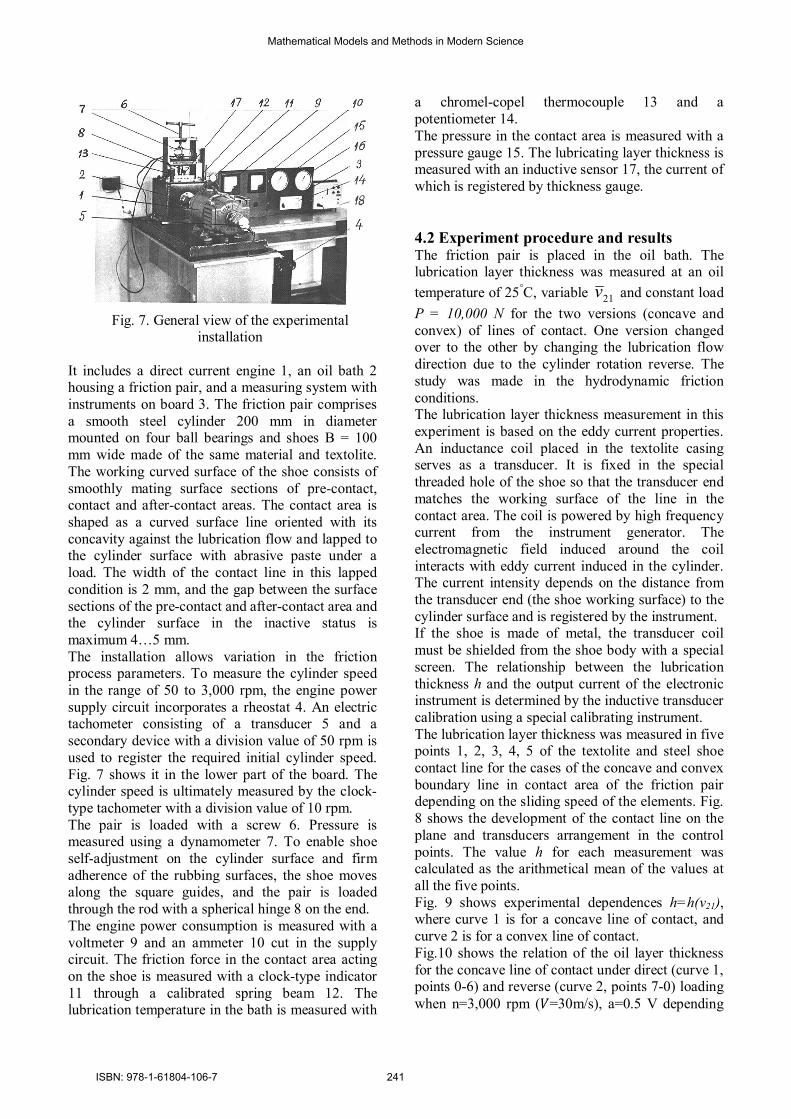
Fig. 7. General view of the experimental
installation It includes a direct current engine 1, an oil bath 2 housing a friction pair, and a measuring system with instruments on board 3. The friction pair comprises a smooth steel cylinder 200 mm in diameter mounted on four ball bearings and shoes В = 100 mm wide made of the same material and textolite. The working curved surface of the shoe consists of smoothly mating surface sections of pre-contact, contact and after-contact areas. The contact area is shaped as a curved surface line oriented with its concavity against the lubrication flow and lapped to the cylinder surface with abrasive paste under a load. The width of the contact line in this lapped condition is 2 mm, and the gap between the surface sections of the pre-contact and after-contact area and the cylinder surface in the inactive status is maximum 4…5 mm. The installation allows variation in the friction process parameters. To measure the cylinder speed in the range of 50 to 3,000 rpm, the engine power supply circuit incorporates a rheostat 4. An electric tachometer consisting of a transducer 5 and a secondary device with a division value of 50 rpm is used to register the required initial cylinder speed. Fig. 7 shows it in the lower part of the board. The cylinder speed is ultimately measured by the clock-type tachometer with a division value of 10 rpm. The pair is loaded with a screw 6. Pressure is measured using a dynamometer 7. To enable shoe self-adjustment on the cylinder surface and firm adherence of the rubbing surfaces, the shoe moves along the square guides, and the pair is loaded through the rod with a spherical hinge 8 on the end. The engine power consumption is measured with a voltmeter 9 and an ammeter 10 cut in the supply circuit. The friction force in the contact area acting on the shoe is measured with a clock-type indicator 11 through a calibrated spring beam 12. The lubrication temperature in the bath is measured with
a chromel-copel thermocouple 13 and a potentiometer 14. The pressure in the contact area is measured with a pressure gauge 15. The lubricating layer thickness is measured with an inductive sensor 17, the current of which is registered by thickness gauge. 4.2 Experiment procedure and results The friction pair is placed in the oil bath. The lubrication layer thickness was measured at an oil temperature of 25°С, variable 21v and constant load Р = 10,000 N for the two versions (concave and convex) of lines of contact. One version changed over to the other by changing the lubrication flow direction due to the cylinder rotation reverse. The study was made in the hydrodynamic friction conditions. The lubrication layer thickness measurement in this experiment is based on the eddy current properties. An inductance coil placed in the textolite casing serves as a transducer. It is fixed in the special threaded hole of the shoe so that the transducer end matches the working surface of the line in the contact area. The coil is powered by high frequency current from the instrument generator. The electromagnetic field induced around the coil interacts with eddy current induced in the cylinder. The current intensity depends on the distance from the transducer end (the shoe working surface) to the cylinder surface and is registered by the instrument. If the shoe is made of metal, the transducer coil must be shielded from the shoe body with a special screen. The relationship between the lubrication thickness h and the output current of the electronic instrument is determined by the inductive transducer calibration using a special calibrating instrument. The lubrication layer thickness was measured in five points 1, 2, 3, 4, 5 of the textolite and steel shoe contact line for the cases of the concave and convex boundary line in contact area of the friction pair depending on the sliding speed of the elements. Fig. 8 shows the development of the contact line on the plane and transducers arrangement in the control points. The value h for each measurement was calculated as the arithmetical mean of the values at all the five points. Fig. 9 shows experimental dependences h=h(v21), where curve 1 is for a concave line of contact, and curve 2 is for a convex line of contact. Fig.10 shows the relation of the oil layer thickness for the concave line of contact under direct (curve 1, points 0-6) and reverse (curve 2, points 7-0) loading when n=3,000 rpm (푉=30m/s), a=0.5 V depending
Mathematical Models and Methods in Modern Science
ISBN: 978-1-61804-106-7 241

on the load increase and reduction in the contact area. Reverse load (point 7) was put at the initial load Р = 3,000 N, zero speed n=0 (which is initially caused by boundary friction), with the speed changing smoothly to 3,000 rpm. Approximately twofold reduction of the lubrication layer thickness (section 6-7 in Fig. 10) seems to be caused by the surface forces in the contact area. We define oil layer stability under direct loading and its origination difficulty under reverse loading as hydrodynamic hysteresis.
Fig.9. Experimental curves ℎ = ℎ(푉 ): 1 – for a concave line of contact; 2- for a convex line of
contact
Fig.10. Lubrication layer thickness under direct (curve 1) and reverse (curve 2) loading of the
contact Fig. 11 illustrates mean values of pressure p measurements at five points in the contact area,
where curve 1 is for a concave line of contact, and curve 2 is for a convex line of contact. The dependence of the friction force FT acting on the shoe on v21 is shown in Fig. 12, where curve 1 is for a concave line of contact, and curve 2 is for a convex line of contact. Fig. 13 shows the lubrication temperature dependence for a concave line of contact – curve 1 and a convex line of contact – curve 2. The curves were plotted for the steady motion when v21=20 m/s; Р = 3,000 N within a fixed time interval tф.
Fig.11 Mean pressure values of the contact area: 1 – for a concave line of contact; 2- for a convex line of
contact
Fig.12 The dependence of the friction force in
concave and convex contact lines on the sliding speed: 1 – for a concave line of contact; 2- for a
convex line of contact
The results obtained make it possible to conclude that the concave line of the contact area in the friction pair is much more effective by its bearing capacity (lubrication layer thickness, pressure), relative motion resistance and temperature than the convex line.
5 Experiment 3. CCL lubrication layer thickness optimization Thus, we have experimentally proved that CCL has higher functional (performance) efficiency as
Fig.8. Contact line with lubrication layer
transducers
Mathematical Models and Methods in Modern Science
ISBN: 978-1-61804-106-7 242
compared to any other shape thereof. Now the challenge is to find an optimal CCL shape under certain conditions. To make it clear whether the maximum h is dependent of the CCL shape, we have made an experimental study to find out whether the shape of the 1st link pre-contact section has an effect on the lubrication layer thickness. Analyzing parameters shown in Fig. 1 makes it possible to assume that the value h can be significantly dependent on the sliding speed 21v ,
load Р , contact area s, width B of the lubrication flow Q , viscosity coefficient μ, shape lj - lj, depth a of its concavity – the depth of the oil pocket (oil trap) and gap gradient (gap variation rate ∆(y)/∆(x)) in the direction of the lubrication flow in the pre-contact area, i.e. h= h (v21, P, s, B, μ, lj - lj, a, ∆(y)/∆(x)).
Fig. 13. Dependence of the temperature in concave
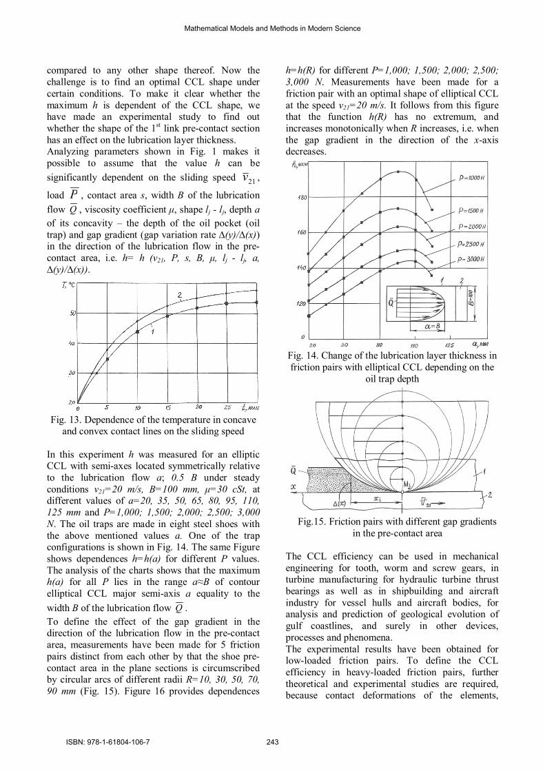
and convex contact lines on the sliding speed In this experiment h was measured for an elliptic CCL with semi-axes located symmetrically relative to the lubrication flow a; 0.5 В under steady conditions v21=20 m/s, B=100 mm, μ=30 cSt, at different values of а=20, 35, 50, 65, 80, 95, 110, 125 mm and Р=1,000; 1,500; 2,000; 2,500; 3,000 N. The oil traps are made in eight steel shoes with the above mentioned values а. One of the trap configurations is shown in Fig. 14. The same Figure shows dependences h=h(a) for different P values. The analysis of the charts shows that the maximum h(a) for all P lies in the range a≈B of contour elliptical CCL major semi-axis a equality to the width B of the lubrication flow Q . To define the effect of the gap gradient in the direction of the lubrication flow in the pre-contact area, measurements have been made for 5 friction pairs distinct from each other by that the shoe pre-contact area in the plane sections is circumscribed by circular arcs of different radii R=10, 30, 50, 70, 90 mm (Fig. 15). Figure 16 provides dependences
h=h(R) for different Р=1,000; 1,500; 2,000; 2,500; 3,000 N. Measurements have been made for a friction pair with an optimal shape of elliptical CCL at the speed v21=20 m/s. It follows from this figure that the function h(R) has no extremum, and increases monotonically when R increases, i.e. when the gap gradient in the direction of the x-axis decreases.
Fig. 14. Change of the lubrication layer thickness in friction pairs with elliptical CCL depending on the
oil trap depth
Fig.15. Friction pairs with different gap gradients
in the pre-contact area
The CCL efficiency can be used in mechanical engineering for tooth, worm and screw gears, in turbine manufacturing for hydraulic turbine thrust bearings as well as in shipbuilding and aircraft industry for vessel hulls and aircraft bodies, for analysis and prediction of geological evolution of gulf coastlines, and surely in other devices, processes and phenomena. The experimental results have been obtained for low-loaded friction pairs. To define the CCL efficiency in heavy-loaded friction pairs, further theoretical and experimental studies are required, because contact deformations of the elements,
Mathematical Models and Methods in Modern Science
ISBN: 978-1-61804-106-7 243

changes in the lubrication temperature and viscosity have a strong impact on the oil wedge origination conditions and friction parameters in such KP. It should be admitted that an optimal shape h of CCL for a general case has not yet been found.
Fig. 16. The dependence of the oil layer thickness
on the gap gradient in the pre-contact area
6 Conclusions 1. On the basis of the above-mentioned, it can be concluded that the phenomenon of increase in the oil layer bearing capacity in the contact of two solid bodies has been found experimentally. It consists in the fact that orientation of the contact line concavity against the lubrication flow increases the bearing capacity thereof due to the absence of the side lubrication outflow and cumulative action of the flow jets resulting from the concentration of their paths in the concavity vertex. 2. It can be stated that the phenomenon of the hydrodynamic hysteresis in the contact of two solid bodies having relative motion in the lubrication flow has been found experimentally. It consists in the fact that orientation of the contact line concavity against the flow makes the minimum thickness of the lubrication layer be dependent on the preceding load caused by the contact surface forces. 3. The priority publications are [6,7]. The publication [8] describes the worm gear with CCL oriented against the lubrication flow carried to the worm threads. The use of a worm reduction gearbox manufactured on its basis has shown, all other
things being equal, a significant reduction in the heat flow radiation intensity, which gives express evidence of CCL gear lubrication bearing capacity increase and friction power reduction. 4. The experimental results can be used as the basis for new lines of mechanical transmission analysis, design of hydroturbines thrust bearings, vessel hulls and aircraft bodies. References [1] Niemann G., Winter H. Maschinenelemente. – Berlin – Heideberg – New York – Tokio, 1983. – B.3. [2] Pedrero Josè I., Pleguezuelos Miguel, Artès Mariano, Antona Juan A. Load distribution model along the line of contact for involute external gears. Mech. And Mach. Theory. 2010. 45, №5, pp.780-794. [3] Litvin Faydor L., Nava Alessandro, Fan Qi, Fuentes Alfonso. New geometry of face worm gear drives with conical and cylindrical worms, generation, Simulation of meshing, and stress analysis. Comput. Meth. Appl. Mech. and Eng. 2002, 191, №27-28, pp. 3035-3054. [4] Theodossiades S. Tangasawi O., Rahnejat H.J. Gear teeth impacts in hydrodynamic conjunctions promoting idle gear rattle. Sound and Vibr. 2007. 303, №3-5, pp. 632-658. [5] Changenet C., Velex PP. A model for the prediction of churning losses in geared transmissions: preliminary results. Trans. ASME. J. Mech. Des. 2007. 129, №1, pp. 128-133. [6] L.V. Korostelev. Kinematic properties of bearing capacity in spatial gearing. Higher Education Institutes: - М.: Machine Building, 1964, No.10, pp. 56-59. [7] V.P. Prokhorov, V.А. Cherenkevich. Effect of the shape and orientation of the contact area line on hydrodynamic interaction between kinematic pair surfaces. Book: Interaction of the rolling stock and railway, locomotive dynamics. Scientific works of Omsk Institute of Railway Transport Engineers, Vol. 165. – Omsk, 1974, pp. 113-118. [8] L.V. Korostelev, S.А. Lagutin, V.P. Prokhorov. Worm gear. Certificate of Authorship No.476390, М.Cl. F16h 1/16 Bulletin of Inventions, No.25, 1975 – p.7.
Mathematical Models and Methods in Modern Science
ISBN: 978-1-61804-106-7 244