THE EFFECT OF STRESS CRACK CORROSION AFTER USING DIFFERENT ... · PDF fileTHE EFFECT OF STRESS...
70
THE EFFECT OF STRESS CRACK CORROSION AFTER USING DIFFERENT PWHT TEMPERATURES ON P91 STEEL SELIN COKGUL DISSERTAÇÃO DE MESTRADO APRESENTADA À FACULDADE DE ENGENHARIA DA UNIVERSIDADE DO PORTO EM ÁREA CIENTÍFICA M 2014 ORIENTADOR PROF. LUÍS FILIPE MALHEIROS
Transcript of THE EFFECT OF STRESS CRACK CORROSION AFTER USING DIFFERENT ... · PDF fileTHE EFFECT OF STRESS...

THE EFFECT OF STRESS CRACK CORROSION AFTER USING DIFFERENT PWHT
TEMPERATURES ON P91 STEEL
SELIN COKGUL DISSERTAÇÃO DE MESTRADO APRESENTADA À FACULDADE DE ENGENHARIA DA UNIVERSIDADE DO PORTO EM ÁREA CIENTÍFICA
M 2014
ORIENTADOR
PROF. LUÍS FILIPE MALHEIROS

i Selin ÇOKGÜL
CANDIDATA: Selin ÇOKGÜL Código: 201200532
Título: Stress Crack Corrosion on P91 Steel after Post Welding Heat Treatment at Different
Temperatures
Data: 29/06/2015
Local Faculdade de Engenharia da Universidade do Porto
JÚRI Presidente: Manuel Fernando Gonçalves Vieira DEMM/FEUP
Arguente: Ana Maria Pires Pinto DEM/UM
Orientadora: Luís Filipe Malheiros de Freitas Ferreira DEMM/FEUP

ii Selin ÇOKGÜL
Acknowledgements
For this dissertation, I would like to express my sincere gratitude to my supervisor Prof. Luís
Filipe Malheiros for the continuous support of my master study and research, for his patience,
motivation, enthusiasm, and immense knowledge. His guidance helped me in all the time of
research and writing of this thesis. I could not have imagined having a better advisor and mentor
for my master study.
My sincere thanks also goes to the owner of the company Eng. António Rebelo, MSc. Fábio
Ribeiro and Alexandre Silva MSc. for supervising me perfectly in TRATERME, offering me the
internship opportunities in their company and leading me working on this exciting projects.
I am also grateful to the best technicians Mr. Baptista for all heat treatment processes and
sharing with me his endless experience, Mr. Armando for welding process, to MSc. Paulo Pereira,
Fernando Sérgio Brandão and MSc. Flávio Silva for my non-destructive tests and to all people,
probably I forgot someone, for guiding to me on this tough journey in my life.
Last but not least, I would like to thank my family: First of all, to Antero Silva for supporting
me unconditionally and bringing my life peace and happiness, then my parents Şennur Kesici
and Murteza Çokgül, and also my beloved brother Uğurcan Çokgül, also supporting me spiritually
throughout my life.

iii Selin ÇOKGÜL
Abstract
This work focuses on the heat treatment of welded joints and was developed in a partnership
with the company TRATERME - Tratamentos Térmicos, L.da.
The importance of the heat treatment is affecting the microstructure to improve the
performance of the material after welding. The crystal structure is rearranged specifically by
changing temperatures. The importance of this rearrangement is to block the ferrite formation.
First of all, this study analyses the effect of 4 different post welding heat treatment
temperatures on P91, which is the abbreviation of the X10CrMoVNb9-1 steel. For this process,
a shielded metal arc welding method with butt joining was used, which was necessary for the
material not to overlap.
The entire process was made according to the standards ASME B31.1 and ASME B31.3.
During sample preparation, all the parameters were the same for all the specimens, except
temperature; the temperatures were 730ºC, 650ºC, 800ºC and 850°C. These selected
temperatures were selected from the isopleth of the ternary Fe-C-Cr phase diagram for 9% (wt.)
Cr. [2]
In the second part of the work, destructive, non-destructive, and mechanical tests were
performed. These tests were necessary to prove the effectiveness of the PWHT on the material
using stress crack corrosion and non-destructive tests.
First part of the results are related with mechanical tests. Different hardness values were
obtained with a bench equipment. For stress crack corrosion test, three different types of non-
destructive tests were needed for monitoring the defects on the corroded area. These results
are contribute to the advance of this field of study, in the future.
Keywords: X10CrMoVNb9-1 steel, P91 steel, welded joint, preheat temperature, PWHT, SCC.

iv Selin ÇOKGÜL
Resumo
Este trabalho foca o tratamento térmico de juntas soldadas e foi desenvolvido em parceira com
a , empresa TRATERME – Tratamentos Térmicos, L. da.
A importância do tratamento térmico é devido ao processo de soldadura, que poderá não
resultar num bom desempenho do componente. Em primeiro lugar, este estudo analisa o efeito
do tratamento térmico pós soldadura, realizado a quatro diferentes temperaturas, em P91, que
é a abreviação do aço X10CrMoVNb9-1. Durante a preparação da amostra, todos os parâmetros
eram idênticos em todos os espécimens, excepto a temperatura. As temperaturas são 730ºC,
650ºC, 800ºC e 850ºC respectivamente, para o espécime-tipo. Estas temperaturas foram
selecionadas da análise da secção vertical do diagrama-fase para %Cr=9. Como método de
soldadura, foi usado soldadura de topo, de acordo com as normas ASME B31.1 e ASME B31.3.
Na segunda parte do trabalho prático, foram executados testes destrutivos, não-destrutivos,
mecânicos e químicos. Estes testes foram necessários para testar a eficácia dos testes PWHT e
SCC.
A primeira parte dos resultados está relacionada com ensaios mecânicos. Para o teste de
corrosão sob tensão, três diferentes tipos de testes NDT forma necessários para monitorizar os
defeitos na área corroída. Os resultados afiguram-se promissores para o futuro.
Palavras-chave: Aço X10CrMoVNb9-1, aço P91, junta soldada, temperatura de préaquecimento,
tratamento térmico após soldadura, microestrutura, PWHT, SCC.

v Selin ÇOKGÜL
Özet
Bu çalışma, sıcaklığın kaynaktan sonra yapılan ısıl işlem üzerindeki etkilerine odaklanmış olup
TRATERME şirketiyle ortaklaşa gerçekleştirilmiş ve geliştirilmiştir.
Kaynak için ısıl işlem daha iyi bir performans sağlaması için önemlidir. Öncelikle bu çalışmada,
X10CrMoVNb9-1 çeliği, kısaltması P91, için 4 farklı kaynak sonrası ısıl işlem sıcaklığı seçilmiştir.
Malzemenin hazırlanması sırasında, bütün parametreler bütün malzemeler için aynı olup,
sadece sıcaklık değiştirilmiştir. Bu sıcaklıklar numune ve deney sırası ile 730 ºC, 650 ºC, 800 ºC,
ve 850 ºC olarak belirlenmiştir. Belirlenen bu sıcaklıklar için P91 çeliğinin faz diyagramının
karbon yüzdesi sabit olarak alınan kesitinden yararlanılmıştır. Kaynak işlemi ve kaynak sonrası
ısıl işlem sıcaklıklar için ASME B31.1 ve ASME B31.3 standartlarından faydalanılmıştır.
Çalışmanın ikinci kısmı uygulamalı olarak gerçekleştirilmiştir. Tahribatlı, tahribatsız numune ve
mekanik testler uygulanmıştır. Bu testler, kaynak sonrası uygulanan ısıl işlemin ve stress
kaynaklı korozyon testlerinin etkilerini ispatlamak açısından oldukça gereklidir. Aynı numune
için uygulanan testler ve alınan sonuçlar yapılan testlerin farklılıkları ortaya çıkmasına yardımcı
olmuştur.
Sonuçların ilk kısmında, sonuçlar mekanik testlerle ilgilidir. Farklı sertlik ölçüm cihazları ile
birbirinden farklı sonuçlar elde edilmiştir. Sertlik testlerinden en iyi sonucu almak için ortamın
tüm sarsıntılardan ve farklı dalga boyları yaratacak etkilerden uzak olması gerekmektedir,
çünkü bu durum elde edilen verilerin doğruluğunu daha kolay ispatlanmasına yardımcı olacaktır.
Stres kaynaklı oluşan korozyon testinde, numunenin farklı alanları için üç farklı tahribatsız
deney yöntemine ihityaç duyulmuş olup, sonuçlar toplanan veriler ışığında değerlendirilmiştir.
Sonuçlar gelecek deneyler için umut vericidir.
Anahtar Kelimeler: X10CrMoVNb9-1 çeliği, P91 çeliği, kaynak sonrası ısıl işlem, stres kaynaklı
korozyon, mikrostrüktür, kaynak öncesi ısıl işlem.

vi Selin ÇOKGÜL
(This page intentionally left blank)

vii Selin ÇOKGÜL
List of Contents
1. Introduction…………………………………………………………………………………………………………………………… 1
2. Literature Review…………………………………………………………………………………………………………………. 2
2.1. Material Description………………………………………………………………………………………………………. 2
2.1.1. Effect of the alloying elements…………………………………………………………………………… 3
2.1.2. Continuous cooling transformation (CCT) diagram…………………………………………….. 5
2.2. Welding Process……………………………………………………………………………………………………………… 7
2.2.1. Shielded metal arc welding (SMAW)……………………………………………………………………. 7
2.3. Microstructural Zones (Base Metal, HAZ and Welding Zone)…………………………………………. 8
2.4. Heat Treatment of P91 Steel………………………………………………………………………………………… 10
2.4.1. Bake-out…………………………………………………………………………………….……………………… 10
2.4.2. Preheating and interpass heating……………………………………………………………………… 11
2.4.3. Post heating…………………………………………………………………………………………………………11
2.4.4. Post weld heat treatment (PWHT)………………………………………………………………………12
2.5. Stress crack corrosion (SCC)…………………………………………………………………………………………. 14
3. Experimental Work……………………………………………………………………………………………………………… 16
3.1. Chemical composition of P91 pipe and welding consumable used in the investigation 16
3.2. Experimental procedure………………………………………………………………………………………………. 16
3.2.1. Sample Preparation…………………………………………………………………………………………… 16
3.3. Metallographic Sample Preparation……………………………….……………………………………………. 19
3.4. Hardness Measurements………………………………………………….…………..……………………………… 19
3.5. Non-Destructive Tests…………………………………………………….……………………………………………. 20
3.5.1. Digital radiography tests of welds……………………….……………………………………………. 20
3.5.2. Dye Penetrant Test……………………………………………………………………………………………. 21
3.5.3. Magnetic Particle Inspection Test……………………….……………………………………………. 21
3.6. Stress Crack Corrosion Test…………………………………………………………………………………………… 23
4. Experimental Results and Discussions…………………………………………………………………………………. 25
4.1. Metallographic Analysis Results…………………………………………………………………………………… 25
4.2. Hardness Measurements Results…………………………………………………………………………………… 27
4.3. SCC Test Results………………………………………………………………..………………………………………… 29
5. Conclusion…………………………………………………………………………………………………………………………… 37
6. References…………………………………………………………………………………………………………………………… 39

viii Selin ÇOKGÜL
List of Figures and Tables
Figure 1: Continuous Cooling Transformation Diagram for P91 steel [2]…………………………………. 6
Figure 2: Scheme of Shielded Metal Arc Welding circuit [9]……………………………………………………… 8
Figure 3: Schematic representation of different heat affected zones [12]…………………….………. 9
Figure 4: SCC variables……………………………………………………………………………………………………………… 15
Figure 5: Assembly of preheating and interpass heating system…………………………………………….. 17
Figure 6: VAI 45 power generator of the induction heat treatment equipment…………………….. 17
Figure 7: Welding Procedure of P91 steel……………………………………………………………………………….. 18
Figure 8: Graphic representation of the 5 hardness measuring zones……………………………………… 20
Figure 9: Assembly of the SCC experiment…………………………………………………………………….………… 24
Figure 10: Microstructure of P91 steel before PWHT, etching with Vilella’s reagent……………. 25
Figure 11: Microstructures of P91 steel base material after PWHT: 1- at 650°C; 2- at 730°C; 3-
at 800°C; and 4- at 850°C, 500x, etching with Vilella’s reagent……………………………………………… 26
Figure 12: Microstructures of P91 steel welding zone after PWHT: 1- at 650°C; 2- at 730°C; 3-
at 800°C; and 4- at 850°C, 500x, etching with Vilella's reagent………………………………………………. 26
Figure 13: Microstructures of P91 steel HAZ and welding zone after PWHT: 1- at 650°C; 2- at
730°C; 3- at 800°C; and 4- at 850°C, 500x, etching with Vilella's reagent……………………………… 27
Figure 14: Hardness values of the specimens before and after PWHT……………………………….…… 28
Figure 15: Liquid penetrant test after PWHT……………………………………………………………….…………. 29
Figure 16: Liquid penetrant test after cutting the pipes: A. Outer surface; B. Inner surface… 30
Figure 17: The results of Radiation Test of P91 steel samples, before SCC test……………………. 30
Figure 18: MPI test of specimen 1 before the SCC test…………………………………………………………… 31
Figure 19: Specimens before SCC tests……………………………………………………………………………….…… 32
Figure 20: Weight change of P91 steel during SCC test………………………………………………………….. 33
Figure 21: SCC test specimens during 6 weeks (A: week 1, B: week 2, C: week 3, D: week 4, E:
week 5, F: week 6)……………………………………………………………………………………………………………………. 34
Figure 22: Radiation test results of SCC test samples after 6 weeks……………………………………… 35

ix Selin ÇOKGÜL
Figure 23: MPI test of specimens after SCC experiment…………………………………………………………… 35
Table 1: ASTM specification of P91 steel [1]……………………………………………………………………….….… 2
Table 2: International specifications of 9%Cr-1Mo steel [2]………………………………………………….…… 2
Table 3: Typical chemical compositions of recent variants of P91 steel [4]………………………..…. 3
Table 4: Chemical composition (wt %) of the P91 pipe used in the investigation…………………… 16
Table 5: Chemical composition (wt %) of the welding consumable [26]…………………………………. 16
Table 6: Processing parameters of PWHT for P91 steel……………………………………………………………. 18
Table 7: Chemical composition of Vilella's reagent [28]…………………………………………………………… 19
Table 8: Hardness values for P91 steel from the supplier………………………………………………………… 28
Table 9: Weight changes of P91 steel samples during SCC test………………………………………………. 32

x Selin ÇOKGÜL
List of Symbols and Abbreviations
AC: Alternating Current.
ACM: Upper critical temperature.
AC1: The temperature at which austenite begins to form on heating.
AC3: In hypoeutectoid steel, the temperature at which transformation of ferrite into austenite
is completed upon heating.
ANSI: American National Standards Institute.
ASME: American Society of Mechanical Engineers.
ASTM: American Society for Testing and Materials.
atm: atmosphere.
BCC: Body Centered Cubic.
BS: British Standard.
CCT: Continuous Cooling Transformation.
DC: Direct Current.
FCC: Face Centered Cubic.
g: gram.
GCHAZ: Grain Coarsened Heat Affected Zone.
GRHAZ: Grain Refined Heat Affected Zone.
GTAW: Gas Tungsten Arc Welding.
HAZ: Heat Affected Zone.
HV: Hardness Vickers.
ISO: International Organization for Standardization.
KISCC: Stress Intensity Factor.

xi Selin ÇOKGÜL
kg: Kilogram.
kHz: Kilohertz.
mL: milliliter.
mm: millimeter.
MPa: Megapascal.
MPI: Magnetic Particle Inspection.
NDT: Non-Destructive Testing.
P: Pipe.
PWHT: Post Welding Heat Treatment.
SCC: Stress Crack Corrosion.
SMAW: Shielded Metal Arc Welding.
UV: Ultraviolet.

xii Selin ÇOKGÜL
(This page intentionally left blank)

1
1. Introduction
Ferritic martensitic 9-12% Cr steels have been developed worldwide over the last two decades
for elevated temperature, nuclear and fossil energy applications. P91 steel is commonly used
for high temperature applications up to 650°C [1].
In this study, P91 ferritic martensitic steel pipe was used. This is a modified creep resisting
steel that presents higher stress values than its previous version (P9). Besides the major alloying
elements such as carbon, chromium, silicon, molybdenum, other micro alloying elements, e.g.
vanadium, niobium and nitrogen, improve the properties of the P91 steel. The major
application areas of this steel are power generating and process industries for components such
as boilers, headers, superheaters, due to its elevated thermal properties.
Mechanical properties of P91 steel are similar compared with the previous grades, yield strength
of 415 MPa (minimum), tensile strength of 585 MPa (minimum), and the mean Vickers hardness
values of HV10 250 at room temperature [2].
Mostly, P91 microstructure is obtained by normalizing and tempering heat treatments. The
normalizing temperature range is between 1040°C and 1080°C and the tempering temperature
range is from 750°C to 780°C [3]. After tempering, the microstructure of the material is a
mixture of tempered martensite with carbide precipitates. Due to precipitation hardening, the
carbide precipitates improve the creep rupture strength of the material.
Despite the fact that P91 steel has high strength, it has been found that the mechanical
properties of the heat affected zone (HAZ) region of weld joints of P91 steel are lower
compared to both base material and welding area. During high temperature service, lower
mechanical properties create cracking problem in HAZ regions.
Creep resistant P91 steel is a high strength alloy that transforms entirely to martensitic
structure during air cooling. Main alloying elements of P91 steel, carbon, molybdenum, and
chromium, decrease the Ms temperature and improve its hardenability.
During welding process, it is impossible to avoid hydrogen formation and the risk of hydrogen
induced cracking. To avoid this crack formation, after welding process, post welding heat
treatment is a very critical process.

2
This thesis focuses on the effect of the stress crack corrosion after post welding heat treatment
process. Microstructural analysis, hardness measurements, and non-destructive techniques
were performed before and after heat treatment in base material, heat affected zones and
welding area.
2. Literature Review
2.1. Material Description
The steel X10CrMoVNb9-1 family, designed by ASTM A335/A 335M – 06, is used in high
temperature applications such as boilers, steam pipes, heaters, etc. The ASTM A335 family,
known as seamless martensitic alloy-steel pipe for high-temperature service, evolves into the
P91 grade (P being the abbreviation of pipe), the material with the highest creep and oxidation
resistance properties [3].
During this evolution, the main difference resides in their chemical composition, with particular
emphasis to the chromium (Cr) content of each grade. Thus, developments and researches on
this material are going on to increase the service temperatures up to 650°C and higher. Due to
this evolution, this alloy was incorporated in an ASTM specification to design P91 steel. This
specification is presented in table 1.
Table 1: ASTM specification of P91 steel [4]
Grade Specification Composition (%)
C Mn P S Si Cr Mo V
P91,
T91
A199, A200,
A213, A335
0.08-
0.12
0.3-
0.6
0.020 0.010 0.20-
0.50
8.00-
9.50
0.85-
1.05
0.18-
0.25
P91 steel has been manufactured all around the world and it has different variety of
international standards as shown in table 2.
Table 2: International specifications of 9%Cr-1Mo steel [5]
Country Standard Grade
USA ASTM A213 T91 (seamless tubing)
USA ASTM A335 P91 (seamless pipe)
UK BS 1503 Gr 91 (forging)

3
Germany DIN 17175 X10 CrMoVNb 9 1
Japan HCM-9S
France NF A 49213 T U Z 10CDVNb 09-01
In ASME code 31.1, P91 steel is supplied in normalized and tempered condition. According to
this code, minimum normalizing temperature is 1050°C and minimum tempering temperature
is 730°C. Before normalizing we should obtain a homogeneous austenitic structure; air cooling
transforms austenite to martensite.
2.1.1. Effect of the alloying elements
The large Cr and Mo contents (table 1) and micro alloying elements such as V and Nb improves
the high temperature properties of P91 steel. Despite the low carbon concentration, it
promotes the hardenability and strength in martensitic steels. For P91 steel, expected hardness
values are between 200 and 263 HV [3]. Hardness increase occurs through solution hardening
by alloying elements such as Mn, Si, Cr, Mo and Nb.
Since the creation of P91 steel, many studies were developed on the effects of the alloying
elements. In the meantime, using ASTM specifications as a main alloying structure, scientists
are developing the varieties of creep resistant steels. Changing the compositions of alloying
elements complement the strength at elevated temperatures. The recent variants of P91 steel
are presented in table 3.
Table 3: Typical chemical compositions of recent variants of P91 steel [6]
Elements
Chemical Composition (wt. %)
ASME specifications
T/P9 T/P91 T/P92 T/P911
Carbon, C Max. 0.15 0.10 0.124 0.105
Silicon, Si 0.20-0.65 0.38 0.02 0.2
Manganese, Mn 0.80-1.30 0.46 0.47 0.35
Phosphorous, P Max. 0.030 0.020 0.011 0.007
Sulphur, S Max. 0.030 0.002 0.006 0.003
Chromium, Cr 8.5-10.5 8.10 9.07 9.16

4
Molybdenum,
Mo 1.70-2.30 0.92 0.46 1.01
Vanadium, V 0.20-0.40 0.18 0.19 0.23
Niobium, Nb 0.30-0.45 0.073 0.063 0.068
Tungsten, W - - 1.78 1.00
Boron, B - - 0.003 -
Nitrogen, N - 0.049 0.043 0.072
Nickel, Ni Max. 0.30 0.33 0.06 0.07
Aluminum, Al - 0.034 0.002 -
The main alloying elements for this family are carbon (C), chromium (Cr), molybdenum (Mo),
nickel (Ni) and vanadium (V). The addition of these alloying elements is usually done in order
to increase hardness, strength and corrosion resistance of the product [6].
P91 (also known as modified 9Cr-1Mo) is extensively used in power plants due to its creep and
corrosion properties at high temperatures. The unique martensitic microstructure of P91
ensures favorable strength and toughness for high temperature applications. Also post welding
heat treatment is the most important and critical step in the fabrication of P91 for obtaining
the desired in service performance.
P91 is a martensitic chromium-molybdenum steel containing tungsten, vanadium, niobium and
nitrogen as micro-alloying elements. The role of each element in the alloy is as follows:
Carbon is the basic alloying element of all steels. It provides high hardness and tensile
strength in carbon low alloys. However, if the steel’s carbon content is higher than standard
range, the material’s weldability decreases.
Chromium is the main alloying element of P91 steel. Cr mainly improves the high
temperature resistance, and also oxidation and corrosion resistance of the P91 steel. Cr is a
carbide former and stabilizer. In P91, the oxidation and corrosion resisting effects are
significant at elevated temperatures.
Molybdenum acts as ferrite stabilizer. Likewise, it increases high temperature strength and
corrosion resistance of P91 steel, and contributes to the hardenability and toughness of the
alloy.

5
Vanadium forms carbide and nitride precipitates which results in finer grains. When
vanadium forms a compound with nitrogen, this reaction creates VN compound that improves
the strengthening properties of the P91 steel.
Nickel enhances corrosion resistance, high toughness, and high temperature strength of the
alloy. It inhibits the δ-ferrite formation, and decreases A1 transformation temperature.
P91 steel presents better creep, tensile and fatigue properties compared with the grades in the
alloy family, being able to resist high pressures (between 170 and 230 bar) and high
temperatures (between 500°C and 600°C).
Some of the key advantages of using P91steel are [1, 5]:
• High creep strength;
• High ductility;
• Good weldability, and the possibility of easy bonding to other martensitic steels;
• Good thermal conductivity and low thermal expansion coefficient;
• Good anticorrosive properties and resistance to aqueous and gaseous environments, including
hydrogen-rich environments;
• Ease of machining.
Due to these properties, P91 is the best material for the high temperature applications such as
boiler superheaters, tube heaters, headers, and duct pipes in infrastructures such as
conventional and nuclear plants, and petrochemical installations.
2.1.2. Continuous Cooling Transformation (CCT) diagram
The isothermal transformation diagram of steel is an important tool for design and development
of processes such as welding and heat treatment. In experiments, constant cooling rates are
usually used. CCT diagrams display the phase transformation behaviour as a function of cooling
rate. It helps to predict the final microstructure and properties of the material which are
resulting from cooling rate. During this transformation, cooling rate affects the final
microstructure. From austenite to pearlite transformation, austenite transforms over a wide
range of temperatures and time; a specimen will have mixed microstructure at the end of the
transformation. An isothermal transformation diagram shows that the time and temperature
relationships are applicable to transformation accomplished at constant temperatures but not
applicable to heat treatments involving transformation under continuous cooling conditions.
Usually, P91 steel is heated to the austenite region and cooled to room temperature gradually
at different cooling rates. Cooling rates depend on type of treatment, size and the shape of the

6
piece [2]. CCT diagrams are widely used to estimate the microstructure and mechanical
properties after continuously cooling from austenitizing temperature.
For P91 steel, to achieve desired properties, such as hardness, microstructure, normalizing and
tempering treatments are vital. In the normalization process, the steel is heated to, and kept
at temperatures approximately 55°C above the upper critical temperature (AC3) to complete
austenitic transformation [7]. When the temperature is uniform, it is allowed to cool to room
temperature in air in order to maintain the homogeneity. Once enough time has elapsed for
the material to achieve a uniform temperature and for homogenization process to take place,
the material is left to cool to room temperature. When the material reaches the room
temperature, it has passed the two most important temperatures, the martensitic phase start
and finishing transformation temperatures [7, 8]. These temperatures are represented in the
continuous cooling transformation (CCT) diagram in figure 1.
Figure 1: Continuous Cooling Transformation diagram for P91 steel [7]
Martensite is a metastable microstructure. The hardening treatment of P91 steel comprises
heating the material to Ac3 temperature to provide a fully austenitic structure and then
normalized to form martensitic structure. If P91 is not cooled rapidly, some retained austenite
may remain in the microstructure, which can cause undesirable properties such as susceptibility
to cracking, low ductility and toughness, after post welding heat treatment process.
Due to the high hardenability of P91 steel, the alloy will have to be tempered, a common
treatment for this material in order to achieve high hardness, minimum distortion and low

7
cracking tendency. Tempering will relieve the residual stresses accumulated during cooling
from normalizing temperatures, and will also contribute towards the increase of the material’s
ductility and toughness. Time, temperature, and cooling rate control have vital importance in
the tempering process. Tempering is performed between 175 and 705°C to gain toughness and
soften the metal [7]. The material is then air-cooled down to room temperature in order to
obtain desired mechanical properties such as high toughness, hardness and ductility and also to
use for stress relief.
The main reasons for conducting the normalizing and tempering heat treatment processes to
the P91 steel are [5]:
Reduce the high strength of the weld metal;
Eliminate the likelihood of cold crack failure;
Achieve residual stresses reduction.
2.2. Welding Process
2.2.1. Shielded Metal Arc Welding (SMAW)
The shielded metal arc welding process is the most widely used welding process in the world.
This process is preferable due to its easiness, and low investment and equipment cost.
Nevertheless, it is one of the most difficult one in terms of required training and experience to
achieve the sought results, since SMAW is a fully manual process.
In this process, materials are bonded when heat from an arc is stabilized between the point of
a welding consumable covered wire and the workpiece of the metal joint to be welded. The
heat of the arc is used for melting the base metal and the tip of the welding electrode. The
electric circuit and its components can be seen in figure 2. When in operation, one of the cables
is connected to the work lead, whilst the other is connected to the electrode holder. Welding
starts when the electric arc is creating a contact between the tip of the electrode and the work
lead. The concentrated heat of the arc melts the tip of the electrode, and then transfers
through the arc into the weld pool. The arc must be moved on the work lead at constant speed,
ensuring a proper arc length is maintained. The arc can reach a temperature up to 5000°C, and
melting of the base material will occur shortly after arc initiation [9].

8
´
Figure 2: Scheme of Shielded Metal Arc Welding circuit [10]
In the SMAW process, both alternating (AC) and direct (DC) currents can be used, although DC
is most commonly used over AC currents. The current only flows in one direction and it brings
advantages over alternating current, such as better control of parameters, less sticking, and
easy arc starting. The electrode cable is connected to the positive pole, whilst the workpiece
is connected to the negative output, thus creating the reverse polarity connection most
commonly used in this process. This type of connection brings good penetration and bead profile
[10, 11].
The advantages of SMAW method are [10, 11]:
• The equipment is easy to use, cheap and portable;
• No need for another filler metal;
• No need for another gas or flux;
• Useful for complex shaped geometries;
• Suitable for most common metals and alloys;
• Allows welding in any orientation.
SMAW welding is widely used in applications such as naval industry, pipelines, offshore
platforms, and steel constructions. Also this method is suitable for welding low and high alloy
steels, stainless steels, and cast iron.
2.3. Microstructural zones (Base Metal, HAZ and Welding Zone)
The zones whose microstructures are affected as a result of welding procedures includes the
base material, the weld metal and the heat affected zone (HAZ).

9
Base metal is the material to be welded. In this region, base material is not affected by the
welding procedure, except the part close to the fusion boundary. Thus, due to the welding
process, the base material is in the circumstance of residual, transverse and longitudinal stress.
Heat Affected Zone (HAZ) is a part of base material which has not been melted during welding
process. In addition to that, the microstructure and mechanical properties have been adjusted.
During welding, HAZ area’s microstructure has been changed by the heat as a consequence of
thermal cycle. Due to the thermal conditions and distance from the fusion line, the HAZ is
divided into three microstructural areas, which are grain refined heat affected zone (GRHAZ),
grain coarsened heat affected zone (GCHAZ), and intercritical heat affected zone. The
importance of these areas are related to its propensity to failures.
Weld material zone involves a mixture of filler metal, which comes from welding consumable,
and base metal. In this zone, filler and base metal fully melted and creates homogeneous
structure [5].
These zones are represented in figure 3.
Figure 3: Schematic representation of different heat affected zones after welding [12]
2.4. Heat Treatment of P91 Steel
Each step of the heat treatment processes has different importance. Application of heat
treatment with precise control of preheat, interpass, and post weld heat treatment operations
are required to ensure that the most favorable mechanical and chemical properties are
obtained. To avoid hydrogen cracking in this alloy, controlling preheat and interpass
temperatures and post-baking operations is necessary. Flame, electrical resistance, electrical
induction heating and furnace heating have been successfully used. Temperature monitoring
10
and control of thermal gradients are important. This is a reason that local flame heating is not
recommended and should not be permitted. Changes in thickness, chimney, and position effects
must also be considered as important factors for controlling thermal gradients.
2.4.1. Bake-out
A post weld bake-out may be of critical importance, especially for heavy sections or when flux-
type processes are used. The process involves maintaining the preheat/interpass temperature
for an extended period of time subsequent to interruption or completion of the welding. To
establish the required processing time, factors such as material thickness, duration of the
exposure of the weld to the heat regime, and the extent of “low hydrogen” practices have to
be considered. When suitable preheat is applied, and carefully selected consumables are used,
bake-out step can be eliminated.
Bake-out is performed to remove excessive hydrogen from the material, formed during
manufacturing, and processing. The main purpose of removing hydrogen is to avoid hydrogen
induced cracking in the welded area or heat affected zone. However, when hydrogen is present,
care must be taken so that the hydrogen partial pressure does not result in material cracking.
For this reason, temperature limitations can be imposed when conducting bake-out [13].
Since the purpose is to promote diffusion to free surfaces, time and temperature should be
carefully selected in accordance with the hydrogen mobility, diffusion, initial and desired
hydrogen content, and temperature restrictions of the material.
It is recommended that the bake-out process is conducted at 230-315°C for 2 to 4 hours. When
specifying experienced based parameters, it is recommended that time be specified as a
function of thickness in order to account for the variable diffusion path with minimum time
requirement. Temperature restrictions may be needed to prevent high temperature hydrogen
attack and adverse metallurgical reactions such as temper embrittlement [14].
2.4.2. Preheating and interpass heating
A typical maximum interpass temperature is 300°C; lower temperatures are acceptable but
higher temperatures should not exceed 370°C in order to achieve adequate mechanical
properties in the heat affected zone and weld metal [14]. The maximum interpass temperature
helps to prevent the possibility of hot cracking due to the silicon and niobium contents of the
weld metal. Field operations rarely have problems with interpass temperature on heavy
sections.

11
These heating processes normally have similar aims and are designed to achieve the minimum
preheat and interpass temperatures. The former is instantaneously applied to the base material
just before welding, and the latter to the weld area surpassing each pass in a multi-pass weld.
The first objective of this process is to restrict hydrogen cracking in the weld metal and heat
affected zone. This goal is accomplished by the interaction of several parameters such as
driving off moisture beyond the start of welding, decreasing the cooling rate, and increasing
the rate of hydrogen diffusion. The second reason for conducting preheating and interpass
heating is the redistribution of solidification stresses, which results in a slower processing rate.
Lastly, the process also reduces the cooling rate in materials that form hard or brittle
microstructural constituents when cooled too rapidly from welding temperatures.
The temperature requirements depend on the composition, time between passes, base material
thickness, preheat temperature, environmental conditions, and heat input from welding. There
are special fabrication codes, by ASME and ANSI, to make sure these requirements are fulfilled.
Most of the welding procedures specify a minimum interpass/preheat temperature that must
be maintained whenever welding takes place. Most of welding procedures also specify the
maximum limit of interpass temperatures, which may not be surpassed prior to depositing the
next pass in the same area. A maximum interpass temperature can be specified for
metallurgical reasons such as maintaining the notch toughness of ferritic steels or corrosion
resistance of austenitic stainless steels and some non-ferrous alloys. It is also specified for the
health and effectiveness of the welder [14].
The literature suggests that 200°C is adequate for preheating P91 welds. Manufacturers
typically aim for 200–250°C, but will go as low as 121°C for root and hot pass layers, thin-walled
components, or when Gas Tungsten Arc Welding (GTAW) is utilized [15].
2.4.3. Post Heating
This process is executed once all heating performed after welding has been stopped, and before
the Post Welding Heat Treatment (PWHT) begins. Therefore, it is generally recognized that post
heating is performed at lower temperature: 149-316°C versus 538-760°C for PWHT [14].
The first aim of post heating is the removal of hydrogen, thus preventing hydrogen induced
cracking. That is also known as delayed cracking since it can occur up to 48 hours after the
weld has been cooled to room temperature. Hydrogen induced cracking can occur when the
introduction of hydrogen from the welding consumables or base material is not adequately

12
controlled, or when preheat/interpass is not sufficient. This failure mode is a special concern
when joining high strength and alloyed steels.
If post heating is considered necessary the minimum preheat/interpass temperature should be
maintained until the application of such post heating.
Usually, post heating is applied in situations where some delay is expected between the
completion of welding and the application of PWHT and is not practical or cost effective to
maintain the preheat/interpass temperature until PWHT. Likewise, a delay may be necessary
before completion of welding. When a delay is not practical to maintain the interpass
temperature during welding, intermediate post heating can be used.
For this process, the ASME standard has fabrication and repair codes, which are generally
associated with temper bead or controlled deposition welding when used as an alternative to
PWHT. It is recommended to specify time as a function of thickness to account for the variable
diffusion path, with a minimum time requirement. Temperatures in the range of 260-316°C for
2 hours (minimum) per 25 mm of thickness are consistent with requirements for carbon and low
alloy steels found in various codes. Nevertheless, based upon concerns with hydrogen trapping,
it appears appropriate to use temperature of 316°C and higher. Temperature restrictions are
necessary due to adverse metallurgical reasons [14, 15, 16].
2.4.4. Post Weld Heat Treatment (PWHT)
Application of PWHT is absolutely necessary with Grade 91 welds, regardless of the pipe
diameter or thickness. PWHT is one of the most important steps in obtaining satisfactory welds.
The PWHT methodology and implementation must be verified to ensure that the welds are in
fact receiving PWHT at the correct temperature. In addition, thermocouples or qualification
testing will be necessary. To obtain reasonable levels of toughness, tempering of the
martensitic microstructure will be essential [14, 16].
Post welding heat treatment is generally performed at a higher temperature and with different
objectives than post heating. As with post heating, PWHT may need to be applied without
allowing the temperature to decrease below the minimum for preheat/interpass.
Local PWHT of carbon and low alloy steels is typically performed below the critical
transformation temperature. The critical transformation temperatures indicate where the
microstructure of steel begins and finally completes a change from body centered cubic (BCC)
to face centered cubic (FCC).

13
There are several reasons why local supercritical post welding heat treatment (such as
annealing or normalizing) above the upper critical transformation temperature is not desirable.
First of all, the temperature gradient fundamental to local PWHT would produce critical
temperature regions. Depending upon the previous heat treatment of the material, this could
result in a deleterious effect upon properties, such as tensile/yield strength, toughness, and
local discontinuities. In addition, low material strength at supercritical temperatures increases
the likelihood of distortion.
PWHT can have both beneficial and detrimental effects. Tempering, relaxation of residual
stresses and hydrogen removal, are all benefits of PWHT. Ensuing benefits, such as avoidance
of hydrogen induced cracking, dimensional stability, and ductility, will result in increased
toughness and corrosion resistance. It is important for PWHT conditions to be determined based
on the desired objectives.
Excessive or incorrect PWHT temperatures and long dwelling times may reduce tensile strength,
creep strength and notch toughness. Notch toughness is mostly caused by embrittlement due
to the precipitates formation. The influence of PWHT on properties generally depends on the
composition of the weld metal and base metal, and previous thermal and mechanical processing
of the base metal [17, 18].
The need for PWHT is consistently driven by direct requirements which are generally triggered
by material type and thickness. In the standards, there are fabrication codes and these codes
provide detailed requirements regarding local PWHT. PWHT is usually aimed at reducing
susceptibility to brittle fracture and also is targeted to improve notch toughness and relaxation
of residual stresses [15, 19].
2.5. Stress Crack Corrosion
Stress crack corrosion (SCC) occurs due to the combination of mechanical stresses in a corrosive
environment. SCC can occur in a numerous ways, and it is a subtle form of corrosion. Likewise,
it may happen unexpected and rapidly, and it will result in failure of the material or leakage.
To initiate SCC, there are three requirements: a susceptible metal, a corrosive environment
and sufficient tensile stress. This type of corrosion is very rare but its consequences are very
expensive and destructive [20].
Austenitic stainless steels suffer from stress corrosion cracking mostly in hot solutions
containing chloride-based compounds. The temperature should be above 70°C for the process

14
occur, though SCC can take place at lower temperatures in some cases, namely acid solutions.
The failure continues at low stresses and normally happens as a result of residual stresses from
welding or fabrication. The cracking is generally transgranular, though it transforms to an
intergranular path as a result of steel sensitization [21].
Stress crack corrosion has three basic mechanisms. The first mechanism is active path
dissolution. The typical active path is the grain boundary, where the segregated impurity
elements can make the passivation harder. This process can initiate without stress; stress,
however, will open a crack, and make diffusion easier, thus promoting corrosion medium
spreading and faster material corrosion. The second mechanism is hydrogen embrittlement.
Hydrogen can diffuse between other atoms faster and easily. The diffused hydrogen can cause
material fracture; it can easily open a cleavage and create intense local plastic deformation.
This deformation leads to embrittlement, and cracking will be either intergranular or
transgranular. Hydrogen has low solubility but high diffusivity in BCC iron. On the other hand,
in FCC iron, hydrogen has high solubility but low diffusivity. This means corrosion of P91 steel
takes longer time compared with ferritic iron. The final property is film induced cleavage. In
this mechanism, the walls of the material and the crack point are covered with a film. Plastic
strain ruptures the film at the crack point, and the crack migrates from the film into the matrix.
The mechanism usually causes a transgranular fracture [22, 23].
For the occurrence of stress crack corrosion, the following three parameters are essential (see
Fig. 4); if one of them is missing, SCC may not take place.
As highlighted in Figure 4, in order to prevent stress crack corrosion, one of the variables needs
to be removed. For example, applying post welding heat treatment will reduce residual stresses
and keep them below critical value. Likewise, selecting less susceptible materials for the
required applications will retard the corrosion process.

15
Figure 4: SCC variables
Design details, such as welds, pits, changes in section, etc., improve the stress concentration
of the material. When the stress concentration of the material should pass the threshold, then
SCC will take place by the effect of corrosive environment. In addition, stress can be produced
as a result of the material service. For example, the material might be exposed to corrosive
environment such as sea water, or a temporary operation that leaves corrosive residues on the
material [21, 23].
Stress
Sensitive Microstructure
Hydrogen
SCC

16
3. Experimental Work
3.1. Chemical composition of P91 pipe and welding consumable used in the
investigation.
In this study, the material was P91 creep resisting steel manufactured by Amal. Table 4 shows
the chemical composition of 5.08mm thick P91 pipe steel which was investigated in the current
work. The P91 steel was supplied as normalized and tempered condition. The received P91
steel structure was tempered martensite and the mean hardness value was 235 HV.
Table 4: Chemical composition (wt %) of the P91 pipe used in the investigation
Composition (wt %)
C Mn Si Ni Cr Mo V P S Al Ti Nb N Zr
0.12 0.6 0.5 0.4 9.50 1.05 0.25 0.002 0.001 0.002 0.001 0.1 0.007 0.001
The welding consumable used were KESTRA under the classification of DIN 8575: E Cr Mo 2 B 26
and AWS 5. 5: E 9018- B3/B3 L. It has 3.25mm wire diameter for the root pass. In table 5, the
chemical composition of the consumable is presented.
Table 5: Chemical composition (wt %) of the welding consumable [24]
Composition (wt %)
C Mn Si Ni Cr Mo V Nb N
0.1 1.0 0.25 0.8 9.0 1.0 0.25 0.08 0.05
3.2. Experimental procedure
Experiments were conducted in three stages: welding, post welding heat treatment at four
different temperatures, and finally testing of all samples by using metallographic examination,
hardness test, Non-Destructive Testing (NDT) and Stress Crack Corrosion (SCC) methods.
3.2.1. Sample preparation
Samples preparation started by a 2 h bake-out process at 200°C, followed by an overnight
cooling. Afterwards, thermocouple were connected to the pipes and previously controlled by
the equipment in order to check connections (figure 5). After verifying the connections, the
pipe was covered with a layer of induction resistant, refractory wool and finally by a blanket.
The equipment was programmed, and preheating and interpass heating processes were started.
17
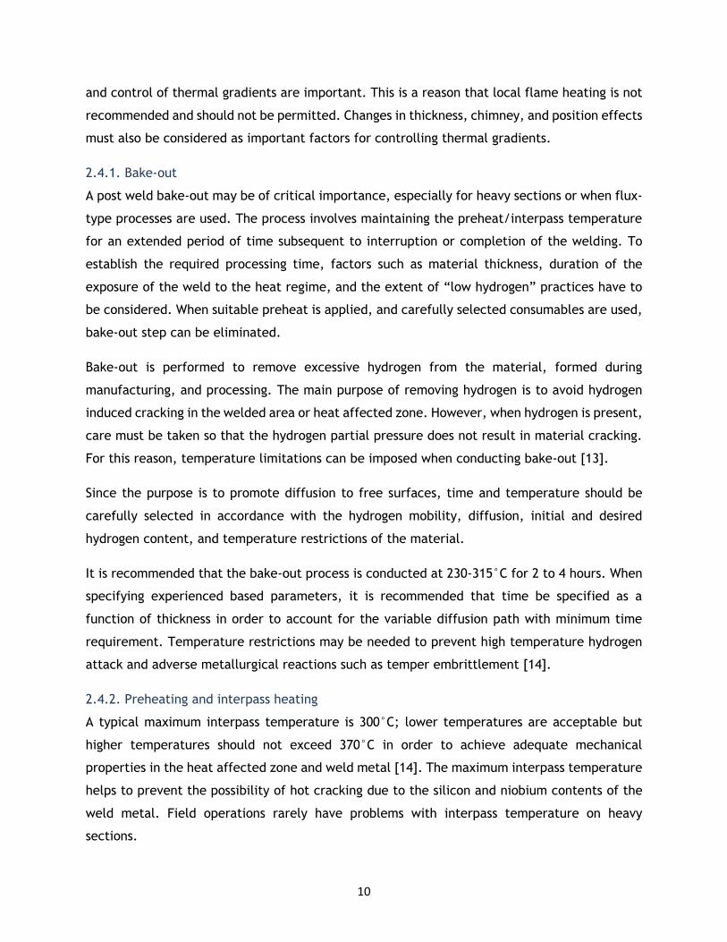
At the same time, electrodes for the welding were inserted in the stove for 1 h for hydrogen
removal. The preheating and interpass heating time-temperature graph is presented in
appendix 1.
Figure 5: Assembly of preheating and interpass heating system
Welding procedure was occurred at TRATERME. The welding process was carried out using SMAW
method. During welding process, the thermal cycle was monitored using embedded
thermocouples. The preheat temperature prior to welding was 200°C, and interpass
temperature was controlled at 250°C ± 10°C.
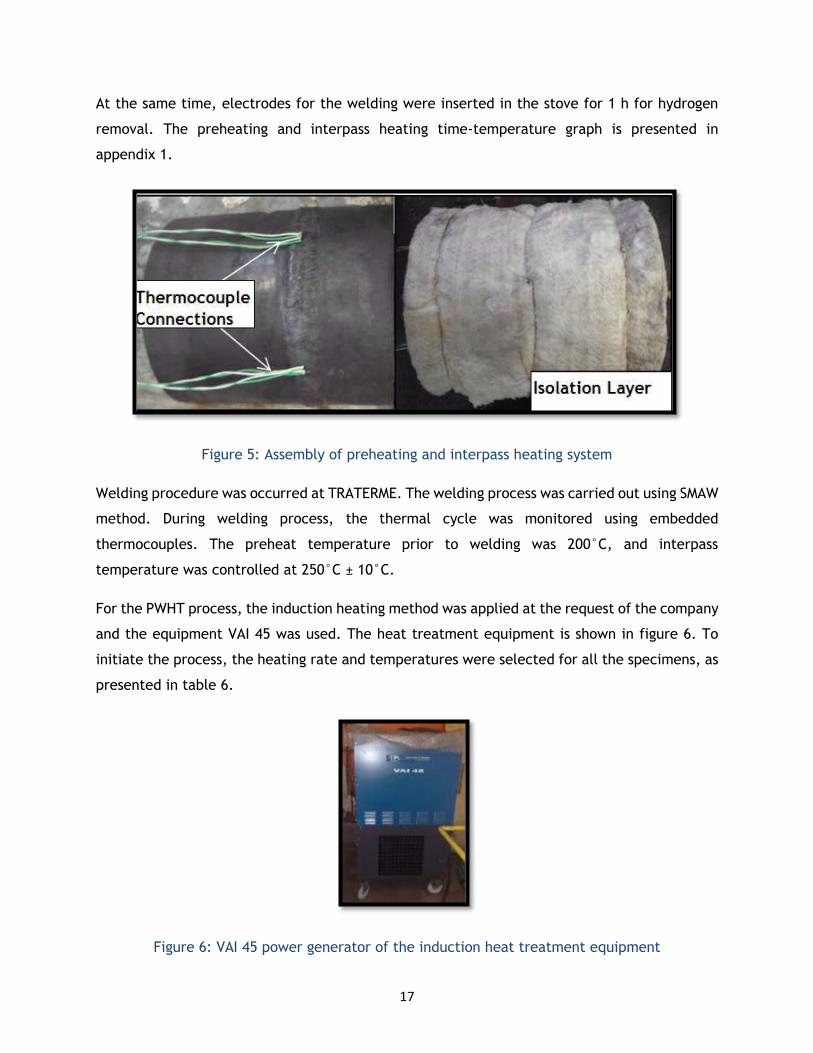
For the PWHT process, the induction heating method was applied at the request of the company
and the equipment VAI 45 was used. The heat treatment equipment is shown in figure 6. To
initiate the process, the heating rate and temperatures were selected for all the specimens, as
presented in table 6.
Figure 6: VAI 45 power generator of the induction heat treatment equipment

18
Table 6: Processing parameters of PWHT for P91 steel
Specimen
Number
PWHT Parameters Temperature
(°C)
1 Lower than transformation temperature 650
2 Standard heat treatment temperature 730
3 Higher than actual PWHT but inside the same
transformation temperature range
800
4 Higher than transformation temperature 850
After welding, all the specimens were heated to 250°C, at a heating rate of 200°C/h. They
were held at those temperatures for 2 h, then cooled at the same cooling rate. The time and
temperature profiles for each heat treatment are shown in appendixes 2, 3, 4 and 5. The
welding procedure of all specimens is presented in figure 7. Post welding heat treatment was
performed at 650°C, 730°C, 800°C and 850°C, respectively.
Figure 7: Welding procedure and PWHT of P91 steel
Once all the PWHTs were complete, all the specimens were subjected to dye penetrant
inspections in order to detect the eventual presence of cracks. After collecting all data, the
pipes were ground by abrasive discs and cut into 4 pieces of certain diameters by an abrasive
cutter. Next, the samples were again inspected using a dye penetrant to check the

19
discontinuities of the inner surface of the pipes. Finally, after all samples were prepared,
destructive, non-destructive, and mechanical tests were conducted before and after SCC test.
3.3. Metallographic Sample Preparation
Characterization of the heat treated samples was implemented using optical microscopy.
Optical microscopy was used to detect general microstructural features.
The specimens for optical microscopic examination were longitudinal sectioned. All samples
were hot mounted by using phenolic mounting resin. In addition, all the specimens were
prepared according to the standard metallographic sample preparation procedure ASTM E3-11
[25]. The samples were then ground by using 180, 220, 320, 400, 600, 800, 1000 and 4000 grit
SiC grinding paper with water as a coolant. For polishing step, a napped cloth with addition of
an aqueous-based colloidal silica suspension and diamond paste was used.
The microstructural features were revealed by etching with Vilella’s reagent, which consists of
picric acid, hydrochloric acid and ethanol (table 7). Vilella’s reagent allows to observe general
structure, grain contrast better than the other etchants for heat treated steels. It etches the
grain boundries where carbides are located.
Table 7: Chemical composition of Vilella's reagent [26]
Chemical Composition Etchant Application
1g Picric acid Dip etching for 30 seconds.
Rinse in alcohol and then dry. 5 mL concentrated HCl
95 mL Ethyl alcohol
3.4. Hardness measurements
The Vickers hardness test is mostly used for small sections. The test procedure, ASTM E-384,
specifies the load to be used along a diamond indenter, to make an indentation which is
measured and converted to a hardness value [27]. This method is convenient for testing a wide
range of metals, ceramics, composites, and other materials, as long as test samples are
carefully prepared. A square-base-pyramid-shaped diamond indenter is used for the Vickers
tests. Typically loads are very small, ranging from a few grams to several kilograms, although
"macro" Vickers loads can range up to 30 kg or more.

20
Macrohardness measurements were implemented by using a Vickers hardness testing machine
for hardness profiles of the welding, HAZ and base material before and after post welding heat
treatment process.
Vickers hardness measurements were performed with a 10 kg load using the Struers hardness
device on each heat treated sample. Recorded hardness values are the average of 5
measurements of the welding, HAZ and base material area. Figure 8 shows the hardness
measurement points on the pipe. The hardness measurements were obtained on samples
mounted in bakelite then polished and etched by Vilella’s reagent.
Figure 8: Graphic representation of the 5 hardness measuring zones
3.5. Non-Destructive Tests
3.5.1. Digital radiography tests of welds
Radiography is one of the most well-known Non-Destructive Tests (NDT). Radiography can be
used to collect permanent image of surface discontinuities. The same discontinuities can be re-
measured after a certain period of service life and the results can be compared to measure the
variation of the discontinuity. The main advantage of this method is to provide more
information about the base material, HAZ and welding area’s microstructure without destroying
the component.
Radiography test was performed under the guidance of the standards: ASTM E-94-04: Standard
Guide for Radiographic Testing, E1030-05: Standard Test Method for Radiographic Examination
of Metallic Castings and E-1416-96: Standard Test Method for Radioscopic Examination of
Weldments [28, 29, 30].
Before starting the examination, all the specimens were cleaned, and fixed on the screen. After
that, the room has to be dark to achieve better quality image. The direction of radiation is
governed by the geometry of the specimen, the radiographic coverage, and quality

21
requirements stipulated by the applicable job order or contract. Whenever practicable, the
central beam of the radiation should be placed perpendicular to the surface of the film. The
standard ASTM E94-04 provides examples of preferred source and film orientations and
examples of specimen geometries and configurations on which radiography is impractical or
very difficult [28].
3.5.2. Dye Penetrant Test
It is a widely applied and low cost inspection method used to locate visible surface defects in
all non-porous materials. The penetrant is applied to all non-ferrous and ferrous metals. This
test is used to detect welding surface defects such as cracks, surface porosity, and leaks on the
surface.
The dye penetrant can be applied to the specimen by dipping, spraying, or brushing. Each dye
penetrant test requires a certain penetration time (10 minutes for this set of experiments); the
excess dye penetrant was removed and a developer applied. The developer helps to draw dye
penetrant out of the flaw so that an indication which cannot be seen with naked eye becomes
visible on the surface, to help the inspector to find the discontinuity, if exists. The key
processing parameters are surface cleaning, penetration time and excess dye penetrant
removing methods [31].
In this test, temperature limits are in the range 10-38°C. Also surface quality is very important
to observe certain discontinuities. The first step for creating a better surface is pre-cleaning.
The aim of this step is to remove all the residuals from the surface. As a surface cleaning agent,
Karl Deutsch check PR-2 was used, as recommended by the ASME-Code, Section V, Article 6
standard [32]. All areas and parts were cleaned and dried before the dye penetrant’s
application. For that reason, the second step was drying. As the dye penetrant used in the
experiment is water based, if there is any liquid residual on the surface, dye penetrant cannot
disperse properly, which can cause incorrect and/or incomplete detection of cracks, pores or
other discontinuities. The third step is the application of the dye penetrant. The dye penetrant
ASME-Code, Section V, Article 6; Karl Deutsch RDP 1: Red dye penetrant was applied. The
inspector has to be sure that all surfaces are covered with dye penetrant.
3.5.3. Magnetic Particle Inspection Test
Magnetic particle inspection (MPI) is a non-destructive testing method used for defect
detection. It is fast and easy to use, and a specific type of surface preparation is not necessary

22
compared to other non-destructive tests. These characteristics make magnetic particle
inspection one of the most widely utilized non-destructive testing methods.
The method is used to inspect a variety of product forms including castings, forgings and welds.
Magnetic particle inspection is widely used in the structural steel construction, automotive,
petrochemical, power plants, and aeronautic industries. Inspection of underwater applications
such as offshore structures and underwater pipelines is another area where this method may
be used.
The magnetic flux density induced in the component depends on the geometry of the
component, its magnetic properties and the selection of a correct flux density is critical for the
regions in which defects are expected to occur. If a flux density of the required value is
established away from the prods, the value can be higher near them. The component has to be
de-magnetized prior to performing magnetic particle inspections. If the component absorbs
some residual magnetism, the sensitivity of the test may be lower and indications can be
incorrectly obtained. The mobility of MPI particles is extremely affected by the presence of
unfamiliar residues, such as dirt, rust, scale, oil or water. Some types of corrosion products will
produce false indications at their boundaries [33].
In this procedure, ASTM E-1444 standard was used as reference [34]. This experiment was
performed under UV light. According to the procedure, magnetic hand-yoke was supposed to
be used but a magnetic coil, due to the shape of the specimen, multi directional movements
and the possibility to show the defects over all the directions of the specimen, is more efficient
than magnetic hand yoke. For the other non-destructive testing methods, pre-cleaning is one
of the main steps. The surface of the part to be examined must be essentially smooth, clean,
dry and free of residuals. The next step is applying the magnetic liquid for render visible all the
defects under UV light. The magnetic inspection media was FLUXA® concentrate containing
magnetic fluorescent powder. Then, the specimen was magnetized by the induced current. The
procedure is accomplished by inductively coupling a part to an electrical coil to create a
suitable current flow. After these steps, the inspector can see the defects and examine them
under UV light. Under UV light, all the pores, defects and other discontinuities are visible in
different color related to their depth. At the end, the specimen must be cleaned with certain
solvents. Parts are examined to ensure that the cleaning procedure has removed magnetic
particle residues from the surface defects such as crevices, holes, etc. [35].

23
3.6. Stress Crack Corrosion Test
In essence, tests for stress corrosion cracking simply require the exposure of the stressed sample
of the material or component in question to the environment of interest. There are different
testing methods for differing objectives:
Standard tests (BS, ASTM, ISO and other standards for example) are generally designed
to test a material for its susceptibility to SCC in a corrosive environment. For example, boiling
42% MgCl2 solution is widely used for testing the susceptibility of austenitic stainless steels to
chloride stress corrosion cracking, and this test may be used to check components for the
presence of residual stresses [36, 37, 38].
Constant stress or constant displacement tests essentially describe the specimen and a
loading method that stresses the specimen while exposed to the solution. The SCC susceptibility
is determined by the time taken for failure of the specimen, or the crack propagation on the
surface of the sample [39].
Fracture mechanics tests use a specimen with a pre-existing crack (often made by
fatigue cycling). The tests can be evaluated by recording the time to failure; however it's more
common to measure the change in crack length with time, and thereby derive a graph of crack
growth rate as a function of stress intensity factor, KISCC [40].
One of the important requirements for SCC is that stresses must be present in the metal. There
is one method for controlling the elimination of that stresses, or at least diminishing the stresses
for SCC.
The most common procedure to reduce residual stresses is annealing. With this procedure it is
possible to minimize residual stresses and thus reduce the probability of cracking. This is widely
applied in carbon steels, due to their high range of stresses tolerance in most environments.
The same is not advisable in austenitic steels as it has a more narrow range of tolerance both
in terms of temperatures and environments [41].
For large structures, this procedure is very difficult to apply; however it can be done, partially
relieving stresses around welds and other risk areas.
For this test, the following standards were used:
• ASTM G36: Stress Crack Corrosion (SCC) resistance of metals and alloys in boiling MgCl2
solution [37].

24
• ASTM G123: Evaluating stainless steel alloys with different nickel content in boiling
acidified NaCl solution [36].
Both standards were combined because of the lack of suitable equipment. The experiment
procedure was based on ASTM G 36 but the test assembly was based on ASTM G123 standard.
The test assembly is shown in figure 9.
Figure 9: Assembly of the SCC experiment
The aim of this test is detecting the effect of composition, heat treatment, surface finishing,
microstructure and the stresses on the metal susceptibility.
Firstly, the solution has to be prepared. It contained 400 mL of distilled water and 600 grams
of MgCl2.6H2O. Magnesium chloride must be completely dissolved in the water in order to
prevent contamination. After preparing the solution, P91 specimens were placed in an
Erlenmeyer flask. A condenser was used for collecting the vapor and keeping the solution in
equilibrium with the solution. Next, the assembly was placed on the hot plate and the
temperature was measured. The ambient conditions, regarding to the standard, have to be 1
atm and 155 ± 1°C. The conditions must be constant for the reliability of the experiment.
Excessive amount of magnesium chloride must not be dumped away for safety reasons. Although
MgCl2 is stable as a solid phase, safety precautions are necessary for boiling solution, which can
cause severe skin burnt. For these reasons, the safety requirements must be strictly followed,
and the test should be performed recurring to fume exhaustion equipment [36, 37].

25
4. Experimental Results and Discussions
In this section of the work, the results of the experimental works are presented. The
experimental results are divided in three sections. These sections cover the metallographic
examination, destructive, non-destructive and stress crack corrosion (SCC) tests. Tests were
performed before and after welding process.
4.1. Metallographic analysis
Before PWHT, the examination of all the samples has proved that they present a tempered
martensite structure which consists of parallel laths inside the grain.
The microstructural changes in P91 steel is based on welding process and post welding heat
treatment application. Different heat treatment cycles were used to test the response of the
metal in terms of structural development and hardness. Figure 10 shows the optical micrograph
of the P91 steel supplied.
Figure 10: Microstructure of P91 steel before PWHT, etching with Vilella’s reagent
During welding process, the rapid thermal cycle creates microstructural differences between
base material and welding area. The amount of parameters to control welding increase the
difficulty of the analysis of the effects of welding variables on weld properties. In this work,
according to the induction heat treatment principles, medium frequency (6-16 kHz) was used.
The heating energy is generated by an inductor. The heat is generated inside the pipe and the
workpiece is heated from inside. With an excessive heat source, welding can result in unique
microstructural features in different regions of the weld.
The microstructures of the samples after PWHT at different temperatures were examined.
These temperatures are presented at table 6. In figure 11, microstructures of base material are

26
presented for different samples after PWHT at four different temperatures. In the
transformation zone, specimen 1, 2, and 3 have typical fine and heterogeneous structure of
P91 steel. Also, precipitates are in different size and distribution, when temperature changes.
For specimen 4, temperature is out of the transformation temperature (850°C) and the
microstructure changes slightly.
Figure 11: Microstructures of P91 steel base material after PWHT: 1- at 650°C; 2- at 730°C; 3-
at 800°C; and 4- at 850°C, 100x, etching with Vilella’s reagent
As presented in figure 12, the black spots are impurities precipitated on the grain boundaries.
These precipitations cause a depletion of chromium near to the grain boundaries which makes
the material anodically active. For specimen 1, the amount of carbide precipitation was lower
and heterogeneously distributed. Also, the precipitates present different sizes. For specimen
2, there is a homogeneous carbide precipitation but the sizes of the precipitates are different.
For sample 3, the grain growth reached the maximum value and they are dispersed on the
welding zone. Finally, specimen 4, partial carbide precipitates disappeared.
Carbon and chromium contents of P91 steel increase the susceptibility of the material, however
other alloying elements increase the effect of sensitization.
Figure 12: Microstructures of P91 steel welding zone after PWHT: 1- at 650°C; 2- at 730°C; 3-
at 800°C; and 4- at 850°C, 100x, etching with Vilella's reagent

27
In figure 13, the microstructures of the HAZ and welding area transitions are presented. For
specimen 1, carbide precipitation was disorderly distributed around the HAZ. For specimen 2,
HAZ was separating the welding area and the base material clearly. In the HAZ, precipitates
were homogeneous and highly concentrated. For specimen 3, it was hard to distinguish the HAZ
between base material and welding area, but in the HAZ area, the size of the precipitates was
fine and homogeneous. Finally, for specimen 4, HAZ area didn’t present precipitates.
Figure 13: Microstructures of P91 steel HAZ and welding zone after PWHT: 1- at 650°C; 2- at
730°C; 3- at 800°C; and 4- at 850°C, 100x, etching with Vilella's reagent
After SCC test, first three specimen had similar structure and reaction to highly corrosive
environment. Specimen 4 was heat treated above the transformation temperature and this
changed the microstructure of the material and the behaviour to the SCC tests.
4.2. Hardness Measurements Results
A large number of measurements have been taken to analyze the variation of the hardness
across the specimens’ sections. Hardness tests were performed before and after post welding
heat treatment process. Hardness values are in the range from a minimum of 180 and a
maximum of 300 HV, in accordance with the standard ASTM A335: High pressure boiler pipes
[3].
For these measurements, 5 points are relative to the base material, heat affected zones (both
side of the weld) and the welding area. These different points where the readings have been
taken are shown in the figure 8.
The hardness results before PWHT were obtained with a Struers MicroHardness device. The
collected hardness values from all the specimens were between the maximum and minimum
limits, in accordance with the standard. Likewise, measured results are compatible with the

28
supplier’s data presented in table 8 and appendix 6. All the measured hardness data are
presented in appendixes 11, 12, 13 and 14.
Table 8: Hardness values for P91 steel from the supplier
Hardness values Sample 1 (HV) Sample 2 (HV)
1 235.0 232.0
2 238.0 233.0
3 236.0 235.0
Mean value 236.33 233.33
In figure 14, before and after PWHT, hardness values increased in all the areas measured.
Welding zone presented the highest hardness values, as expected. The hardness measurements
are between 210-252±23.3 HV10 before PWHT, and they are slightly higher to the values 214-
283±20.0 HV10 obtained after PWHT.
Figure 14: Hardness values of the specimens before and after PWHT
Mechanical and microstructural properties of the material are interrelated. However, the
microstructural differences were not significantly reflected in the overall hardness profiles of
all the samples. After PWHT, the base material and welding zone hardness values were similar;
only difference was registered in the left HAZ. The difference could result from the grain size
200
210
220
230
240
250
260
270
280
290
300
Base(BeforePWHT)
Base Left Weld Right Base
Mean values of the hardness data
Specimen 1
Specimen 2
Specimen 3
Specimen 4

29
distribution on the HAZ. For specimen 3, in left HAZ, there was finer grain size and the hardness
increased.
In conclusion, all the hardness measurements before and after PWHT matched with the
supplier’s data as well as the standard, which means the heat treatment was successful. Also
the results show that there are no significant hardness changes between the zones and they are
between the maximum and minimum values of the standard.
4.3. SCC test results
After finishing the sample preparation, all samples surfaces were cleaned (necessary for surface
examination) and polished until a clear finishing was achieved. The dye penetrant test was
performed following ASTM E 165-95: Standard test method for liquid penetrant examination
standard [41].
Dye penetrant test was performed on the external and internal surfaces of the material. Firstly,
as seen in Figure 15, specimens were a single piece. Then, specimens were cut; liquid penetrant
test was performed again to confirm there was no crack. Dye penetrant was applied to the test
material and red points around the welding area were indicating the height differences of the
sample.
Figure 15: Liquid penetrant test after PWHT
As per figure 15, it was very hard to examine the inner surface of the tube. Defects were mostly
located in the welded zone, but there were rare discontinuities on the base material. An
attempt was made to remove these defects using abrasive discs, with most of them being
removed from the surface. If the defect was deep, those specimens were separated from the
others. According to the standard [31, 41], deep defects are not acceptable, because they can
be a crack, thus compromising the integrity of the piece. For the SCC tests, the specimens used
were those without visible surface cracks.

30
Figure 16: Liquid penetrant test after cutting the pipes: A. Outer surface; B. Inner surface
Before starting the stress crack corrosion tests, all the specimens were examined and the best
ones, in terms of defect concentration, were selected. In figure 17, dark spot in specimen 1
and specimen 3 were visible, an indication of small pores as marked. They are negligible
according to the standard [28, 29, 30]. Darker areas represent high intensity, (in this case, the
welded areas, due to their higher intensity relative to the base material). The results of the
radiation test performed before SCC are presented in appendixes 7 and 8.
Figure 17: The results of Radiation Test of P91 steel samples, before SCC test
In the MPI test, specimen 4 had a 4.02 mm crack. According to the standard, if the crack is
greater than 4.0 mm, then specimen cannot be selected. This specimen was eliminated and
31
replaced by another specimen. Report and the image of the MPI test before SCC test for
specimen 4 are presented in appendixes 9 and 10, respectively.
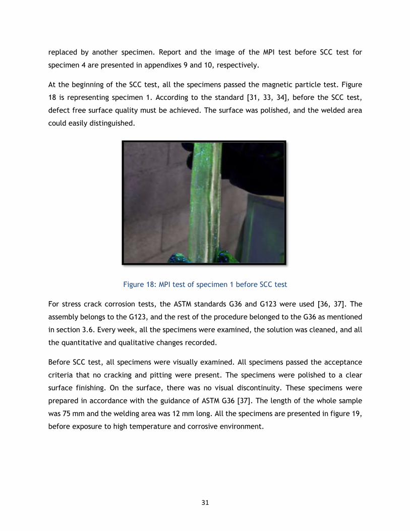
At the beginning of the SCC test, all the specimens passed the magnetic particle test. Figure
18 is representing specimen 1. According to the standard [31, 33, 34], before the SCC test,
defect free surface quality must be achieved. The surface was polished, and the welded area
could easily distinguished.
Figure 18: MPI test of specimen 1 before SCC test
For stress crack corrosion tests, the ASTM standards G36 and G123 were used [36, 37]. The
assembly belongs to the G123, and the rest of the procedure belonged to the G36 as mentioned
in section 3.6. Every week, all the specimens were examined, the solution was cleaned, and all
the quantitative and qualitative changes recorded.
Before SCC test, all specimens were visually examined. All specimens passed the acceptance
criteria that no cracking and pitting were present. The specimens were polished to a clear
surface finishing. On the surface, there was no visual discontinuity. These specimens were
prepared in accordance with the guidance of ASTM G36 [37]. The length of the whole sample
was 75 mm and the welding area was 12 mm long. All the specimens are presented in figure 19,
before exposure to high temperature and corrosive environment.

32
Figure 19: Specimens before SCC tests
The weight variation test was also performed with different samples to measure the weight loss
during SCC test. The solution was prepared using the same procedure for SCC test. All the
samples were previously weighed and placed into the solution. During 5 weeks, all the
specimens were removed from the solution, cleaned with alcohol and dried. Each sample was
then weighed and the difference in weight was used to determine the corrosion rate. All the
data are presented in table 9.
Table 9: Weight changes of P91 steel samples during SCC test
Sample
Initial
weight
(g)
Week
1 (g)
Week
2 (g)
Week
3 (g)
Week
4 (g)
Week
5 (g)
Standard
Deviation
1 187.2 187.4 187.3 187.2 187.5 184.4 1.2
2 183 183.1 183.1 183 185.5 182.3 1.1
3 168.9 169.4 169.4 169.2 170.4 167.8 0.8
4 183.9 184.2 184.1 184 185.7 181.6 1.3
During the first three weeks, the experiment was evolving as expected; however on week 4,
there was an incident in the laboratory and the experiment was affected; the samples were

33
contaminated by the MgCl2 salt and the weight increased unexpectedly. After the
contamination, all the samples were cleaned with alcohol and the solution was changed for a
“clean” one. After a week, the weight results were decreasing rapidly (figure 20).
Figure 20: Weight change of P91 steel during SCC test
The specimens stayed inside the solution for 6 weeks. After this period, the visual changes on
the specimens were related to the color and surface texture changes; a clearer view of the
welding area was obtained (see Figure 21).
0
50
100
150
200
250
1 2 3 4
Initial weight (g) Week 1 (g) Week 2 (g) Week 3 (g) Week 4 (g) Week 5 (g)

34
Figure 21: SCC test specimens during 6 weeks (A: week 1, B: week 2, C: week 3, D: week 4, E:
week 5, F: week 6)
All specimens were inspected by using magnetic particle inspection and radiation methods after
SCC test. Corrosion occurred on the surface as a thin layer. As traditional testing methods would
compromise the uniformity of the material, non-destructive techniques were selected to
control the corrosion on the surface.
In figure 22, sample 1 had a serious crack initiation, and if the experiment had been continued,
the crack would propagate from the middle of the specimen. Sample 4 also had a point defect
on the surface and the depth of the defect showed that instead of stress crack corrosion,
general corrosion had occurred on the surface. Radiation test showed not only the
discontinuities of the specimens after SCC tests, but also the surface defects that appeared on
the surface.

35
Figure 22: Radiation test results of SCC test samples after 6 weeks
After 6 weeks, all the specimens exhibited cracks. For specimen 1, the crack was detected via
the radiation test. To confirm the results, MPI testing was also performed. In figure 23, the
results of MPI test show that cracks occurred on the surface of the samples; the cracks were
2.52, 3.04, 2.20 and 2.86 mm long, respectively. The radiation and MPI reports after SCC testing
are presented in appendixes 15 and 16.
Figure 23: MPI test of specimens after SCC experiment
SCC occurring in service in welded P91 steel may be dependent of a combination of
susceptibility of the weld and HAZ, and the corrosive effect of the environment. In some cases,
highly aggressive environments creates general corrosion rather than SCC or neither of them.
36
5. Conclusion
After finishing the proposed study of the effect of SCC after post welding heat treatment using
different temperature to welded P91 steel, the conclusions presented below were established:
- Heat treatment between 650°C and 730°C is more acceptable, because mechanical
properties of P91 steel is important at high service temperature and pressure. In
addition, higher hardness values in the welding zone are not desirable.
- Martensitic structure of P91 steel requires careful selection of preheat, interpass and
PWHT to avoid stress crack corrosion.
- During 6 weeks of SCC experiments, weight loss and corrosion were achieved, but there
are no significant findings of crack initiation. To minimize the risk of stress crack
corrosion, the inspection frequency should be suitable according to the applications of
the material and the capability of the facilities. This way, cracks can be detected in an
early stage, and preventive methodologies applied before failure.
Some possible routes for improvement to be explored in future work may include the
comparison of the effect of stress crack corrosion after PWHT with different type of welding
methods such as TIG versus SMAW.

37
(This page intentionally left blank)

38
6. References
[1] JARA, D. R., 9-12% Cr heat resistant steels: alloy design, TEM characterization of
microstructure evaluation and creep response at 650°C, dissertation, Bochum, Germany, 2011.
It is available:
http://www-brs.ub.ruhr-uni-bochum.de/netahtml/HSS/Diss/RojasJaraDavid/diss.pdf
[2] http://www.piyushsteel.com/alloysteel-standard-products/astm-A335-asme-sa335-
pipetube/pipetube-type-astma335-asmesa335-p91-alloysteelpipes.html
[3] ASTM A335-11, Standard Specification for Seamless Ferritic Alloy-Steel Pipe for High-
Temperature Service. It is available: http://www.astm.org/Standards/A335.htm
[4] ASM Handbook, Vol. 1.
[5] SULAIMAN S., Structure of properties of heat affected zone of P91 creep resistant steel,
University of Wollongong, 2007.
[6] http://www.journalamme.org/papers_vol19_2/1309.pdf
[7] ASM Handbook, Vol. 4.
[8] BLAIR M., STEVENS T. L., Steel Castings Handbook, 1995, 6th Edition, chapter 24-part 9.
[9]KOU, S. 2002. Welding Metallurgy. Wiley, 2ªed.
[10] http://uotechnology.edu.iq/dep-production/lectures/WL2.pdf
[11] http://www.ewf.be/media/documentosdocs/doc_82_mmaw_tecnical_bulletin.pdf
[12] http://www.globalspec.com/reference/80962/203279/chapter-14-the-weldability-of-
steel
[13] ASME, boilers and pressurized vessels code: 31.3. It is available: https://www.asme.org/products/codes-standards/b313-2012-process-piping
[14] AWS (American Welding Society) = Recommended Practices for Local Heating of Welds in
Piping and Tubing, Handbook, 1999, Vol. D10.
[15] The American Society of Mechanical Engineers (ASME), ASME Boiler & Pressure Code: II-A:
Ferrous Material Specifications, 2007, USA.
[16] http://www.jflf.org/pdfs/papers/keyconcepts4.pdf

39
[17] LANCASTER, J Handbook of Structural Welding, 2003, Abington Publishing.
[18] FUNDERBURK, R. S., Post Weld Heat Treatment, Journal, Welding Innovation Vol XV, NO:
2, 1998, Sec. Key Concepts of Welding Engineering.
[19] Olabi, A. G., HASHMI, M. S. J. The effect of post-weld heat treatment on mechanical
properties and residual stresses mapping in welded structural steel, 1994, School of Mechanical
and Manufacturing Engineering, Dublin City University, Dublin, Ireland.
[20] JONES, R. H., Stress Corrosion Cracking, ASM International, 1992.
[21] YAGHI A. H., HYDE T. H., BECKER A. A., WILLIAMS, J. A., SUN, W., Residual stress simulation
in welded sections of P91 pipes, journal of materials processing technology, 2005.
[22] RHODES, P. R. Mechanism of Chloride Stress Corrosion Cracking of Austenitic Stainless
Steels, Corrosion journal, 1969.
[23] QIAO, L., MAO, X., CHU, W., The role of hydrogen in stress-corrosion cracking of austenitic
stainless steel in hot MgCl2 solution, Metallurgical and Materials Transactions book, volume 26,
1995.
[24] http://www.kestra.com.br/PDF/consumiveissoldagem.pdf
[25] ASTM International, ASTM E3-11, Standard Guide for Preparation of Metallographic
Specimens. It is available: http://www.astm.org/Standards/E3.htm
[26] ASM Handbook, Vol 9, Metallography and Microstructures, 1990.
[27] ASTM International, ASTM E-384-08, Standard Test Method for Microindentation Hardness
of Materials. It is available: http://wenku.baidu.com/view/c3d74c0d7cd184254b3535c6
[28] ASTM International, ASTM 94-04, Standard Guide for Radiographic Testing.
[29] ASTM International, ASTM E1030-05: Standard Test Method for Radiographic Examination
of Metallic Castings.
[30] ASTM International, ASTM E-1416-96: Standard Test Method for Radioscopic Examination of
Weldments.

40
[31] ASTM INTERNATIONAL (American Society for Testing and Materials). 2013, E1417-13
Standard Liquid Penetrant Testing, ASTM International.
[32]http://www.irss.ca/development/documents/CODES%20&%20STANDARDS_02-28-
08/ASME%20V%201998/ASME%20V%20Art%206%20PT.pdf
[33] https://eis.hu.edu.jo/upload/38000000/Magnetic%20Particle%20Testing.pdf
[34] ASTM International, ASTM E E-1444: Standard Practice for Magnetic Particle Examination.
It is available: http://www.tlndt.com/upload/uppic/2009/12/2009122210270947920.pdf
[35] http://www.aero.ing.unlp.edu.ar/catedras/archivos/ASTME%20709%20%2008.pdf
[36] ASTM INTERNATIONAL (American Society for Testing and Materials), 2011, G123-00:
Standard Test Method for Evaluating Stress-Corrosion Cracking of Stainless Alloys with Different
Nickel Content in Boiling Acidified Sodium Chloride Solution, ASTM International.
[37] ASTM INTERNATIONAL (American Society for Testing and Materials), 2013, G36-94: Standard
Practice for Evaluating Stress-Corrosion-Cracking Resistance of Metals and Alloys in a Boiling
Magnesium Chloride Solution, ASTM International.
[38] ISO (International Organization for Standardization), ISO 7539-11:2013, Corrosion of metals
and alloys -- Stress corrosion cracking -- Part 11: Guidelines for testing the resistance of metals
and alloys to hydrogen embrittlement and hydrogen-assisted cracking.
[39] ASTM INTERNATIONAL (American Society for Testing and Materials), 2009, G30-97: Standard
Practice for Making and Using U-Bend Stress-Corrosion Test Specimens, ASTM International.
[40] Dietzel, W., Ghosal, S. K., Stress Corrosion Cracking- A New Approach to Testing Methods,
Journal of Material Science, Vol.33, No. 4, 1997, p. 516.
[41] ASTM International, ASTM E165-95: Standard test method for liquid penetrant examination
standard. It is available: https://elmundodelacalidad.files.wordpress.com/2009/07/asme-sec-
v-b-se-165-examen-con-liquidos-penetrantes.pdf

41
(This page intentionally left blank)

I Selin ÇOKGÜL
Appendixes
1. Graph of the Preheating and Interpass Heating
2. Graph of the PWHT of Specimen 1

II Selin ÇOKGÜL
3. Graph of the PWHT of Specimen 2
4. Graph of the PWHT of Specimen 3

III Selin ÇOKGÜL
5. Graph of the PWHT of Specimen 4
IV Selin ÇOKGÜL
6. Inspection Certificate of the P91 Steel

V Selin ÇOKGÜL

VI Selin ÇOKGÜL
VII Selin ÇOKGÜL

VIII Selin ÇOKGÜL

IX Selin ÇOKGÜL
7. Picture of the Radiation Test Samples before SCC test
4 1 2 3
4 1 2 3

X Selin ÇOKGÜL
8. Radiation Test Report before SCC test

XI Selin ÇOKGÜL
9. Magnetic Particle Analysis Report before SCC test

XII Selin ÇOKGÜL
10. MPI Test Samples before SCC
11. Hardness Values of the Specimen 1, before and after PWHT
This drawing represents the indentation zones of hardness measurements. In each zones, 5
hardness values were registered.
Hardness Tests before PWHT
Specimen 1
1 2 3 4 5
Random 232.5 239.3 239.3 239.3 239.3
Random 222.2 228.5 243.6 261.8 255.5
Average 227.4 234 241.5 250.6 247.4
Standard Deviation 7.28 7.64 3.04 15.91 11.46
Hardness Tests After PWHT
Sample 4

XIII Selin ÇOKGÜL
Specimen 1
1 2 3 4 5
Base 232 238 237 238 236
Left 255 214 257 235 224
Weld 273 268 278 284 273
Right 257 232 245 255 228
Base 263 250 287 256 269
Average 236.6 237.4 243.4 243.4 265
Standard Deviation 2.43 18.75 6.20 13.12 14.23
12. Hardness Values of Specimen 2, before and after PWHT
Hardness Tests with Before PWHT
1 2 3 4 5
Random 220.9 223.3 218.4 224.6 220.9
Random 268.1 270 258.6 258.6 287.4
Average 244.5 246.65 238.5 241.6 254.15
Standard Deviation 33.38 33.02 28.43 24.04 47.02
Hardness Tests with After PWHT
1 2 3 4 5
Base 289 262 251 239 299
Left 273 282 235 228 258
Weld 285 300 235 265 298
Right 229 228 242 262 273
Base 297 229 279 210 271
Average 268 255.2 276.6 246.8 257.2
Standard Deviation 25.33 23.40 27.11 20.1 36.3
13. Hardness Values of Specimen 3, before and after heat treatment
Hardness Tests with Before PWHT
1 2 3 4 5
Random 213.6 211.3 212.5 205.6 209

XIV Selin ÇOKGÜL
Random 252.4 268.2 266.5 245 255.4
Average 233 239.75 239.5 225.3 232.2
Standard Deviation 27.44 40.23 38.18 27.86 32.81
Hardness Tests with After PWHT
1 2 3 4 5
Base 275 282 288 228 247
Left 286 288 271 294 249
Weld 276 292 286 218 258
Right 218 228 242 204 206
Base 258 247 241 255 271
Average 262.6 267.4 265.6 239.8 246.2
Standard Deviation 26.8 28.3 22.96 35.6 24.4
14. Hardness Values of Specimen 4, before and after heat treatment
Hardness Tests with Before PWHT
1 2 3 4 5
Random 213.6 211.3 212.5 205.6 209
Random 227.3 230 235.2 235.2 248
Average 220.45 220.65 223.85 220.4 228.5
Standard Deviation 9.69 13.22 16.05 20.93 27.58
Hardness Tests with After PWHT
1 2 3 4 5
Base 258 287 239 224 283
Left 225 217 221 204 211
Weld 270 307 256 244 260
Right 229 225 223 221 256
Base 214 284 261 297 215
Average 239.2 264 240 238 245
Standard Deviation 23.7 40.3 18.4 35.9 31

XV Selin ÇOKGÜL
15. Magnetic Particle Analysis Report after SCC test

XVI Selin ÇOKGÜL
16. Radiographic Test Report after SCC test