The Effect of Heat Treatment on Interface Properties of S45C
8
Tamkang Journal of Science and Engineering, Vol. 6, No. 1, pp. 49-56 (2003) 49 The Effect of Heat Treatment on Interface Properties of S45C Steel/Copper Compound Casting Jin-Shin Ho, C. B. Lin and C. H. Liu Department of Mechanical and Electromechanical Engineering Tamkang University Tamsui, Taiwan 251, R.O.C. E-mail: [email protected] Abstract The bonding of an S45C steel inserted into copper during cast welding and heat treatment was examined. The interface shear strength was made with a push-out test. After cast welding, a cast-welding layer formed between steel and copper. After marquenching, martempering and austempering heat treatment, there was a cast-welding layer near the steel matrix, an irregular layer near the copper matrix and between of them was a middle layer. Through X-ray diffraction analysis was used to determine that the interface layer consisted of carbon and CuFeO 2 . Through electron probe X-ray microanalysis (EPMA), it was showed that iron atoms and carbons, mostly, diffused into the copper matrix. The interface shear strengths of the compound casting while with marquenching, martempering, and austempering were 6.29 MPa, 8.23 MPa, and 8.33 MPa, respectively; The fractured region was all happened near S45C steel matrix in the cast welding layer. Key Words: S45C, Copper, Cast Welding, Marquenching, Martempering, Austempering 1. Introduction When copper alloy was used as the electrical contact material, incorporating a strengthening phase to a copper matrix to form copper matrix composites was often employed in improving wear properties. For example, the TiO 2 particulate reinforced copper matrix could be used to promote mechanical properties [1]. Under in situ processing of aluminum, titanium and boron elements were remelted, and with the exothermic reaction, 0.05 µm TiB 2 particulate of distributing uniformly in copper matrix were formed. The conductivity of copper matrix containing 5 vol% TiB 2 particulate could reach 76% of the international annealed copper standard, resistance was 1.724 × 10 -6 ohm/cm -2 ⋅cm -1 at 20°C. However, when working temperature was over 500°C, 80% international annealed copper standard was needed to obtain a fine conductivity [2,3]. The bonding strength is significant for determining the quality of wettability between two kinds of metals or metal and nonmetal [4]. During the reaction of Ti and SiC, there was a thermodynamic driving force to make Ti and SiC to produce interlayer in the interface [5]. When a solid solution interlayer was formed in the interface between NiO and Pt could raise the shear stress of the interface [6]. When a hard and brittle intermetallics compound was formed in the interface would be fail the fracture toughness [7]. According to Evans et al. [8], the appearance of interface cracks was mainly affected by two parameters: energy release rate and mode mixity angle (ψ) (definition: ψ﹦0 means open cracks; ψ﹦ π/2, shear cracks.). After being heated treatment could be affected interface properties, According to Klomp [9], heat treatment with different conditions made different bonding strength presented in the interface of composites. Under melting point, Ma Qian et al. [10] added steel wire
-
Upload
ramon-brown -
Category
Documents
-
view
236 -
download
4
description
Heat Treatment
Transcript of The Effect of Heat Treatment on Interface Properties of S45C
Tamkang Journal of Science and Engineering, Vol. 6, No. 1, pp. 49-56 (2003) 49
The Effect of Heat Treatment on Interface Properties of S45C Steel/Copper Compound Casting
Jin-Shin Ho, C. B. Lin and C. H. Liu
Department of Mechanical and Electromechanical Engineering
Tamkang University Tamsui, Taiwan 251, R.O.C.
E-mail: [email protected]
Abstract
The bonding of an S45C steel inserted into copper during cast welding and heat treatment was examined. The interface shear strength was made with a push-out test. After cast welding, a cast-welding layer formed between steel and copper. After marquenching, martempering and austempering heat treatment, there was a cast-welding layer near the steel matrix, an irregular layer near the copper matrix and between of them was a middle layer. Through X-ray diffraction analysis was used to determine that the interface layer consisted of carbon and CuFeO2. Through electron probe X-ray microanalysis (EPMA), it was showed that iron atoms and carbons, mostly, diffused into the copper matrix. The interface shear strengths of the compound casting while with marquenching, martempering, and austempering were 6.29 MPa, 8.23 MPa, and 8.33 MPa, respectively; The fractured region was all happened near S45C steel matrix in the cast welding layer. Key Words: S45C, Copper, Cast Welding, Marquenching, Martempering,
Austempering
1. Introduction When copper alloy was used as the electrical
contact material, incorporating a strengthening phase to a copper matrix to form copper matrix composites was often employed in improving wear properties. For example, the TiO2 particulate reinforced copper matrix could be used to promote mechanical properties [1]. Under in situ processing of aluminum, titanium and boron elements were remelted, and with the exothermic reaction, 0.05 µm TiB2 particulate of distributing uniformly in copper matrix were formed. The conductivity of copper matrix containing 5 vol% TiB2 particulate could reach 76% of the international annealed copper standard, resistance was 1.724 × 10⁻⁶
ohm/cm-2⋅cm-1 at 20°C. However, when working temperature was over 500°C, 80% international annealed copper standard was needed to obtain a fine conductivity [2,3].
The bonding strength is significant for
determining the quality of wettability between two kinds of metals or metal and nonmetal [4]. During the reaction of Ti and SiC, there was a thermodynamic driving force to make Ti and SiC to produce interlayer in the interface [5]. When a solid solution interlayer was formed in the interface between NiO and Pt could raise the shear stress of the interface [6]. When a hard and brittle intermetallics compound was formed in the interface would be fail the fracture toughness [7]. According to Evans et al. [8], the appearance of interface cracks was mainly affected by two parameters: energy release rate and mode mixity angle (ψ) (definition: ψ﹦0 means open cracks; ψ ﹦ π/2, shear cracks.). After being heated treatment could be affected interface properties, According to Klomp [9], heat treatment with different conditions made different bonding strength presented in the interface of composites. Under melting point, Ma Qian et al. [10] added steel wire
50 Jin-Shin Ho et al.
to molten white cast iron, finding that some features of austenite steel or phase transformation were left in the interface of steel and iron.
Pushing out and pulling out were frequently used to test interface shear strength [11]. Observing the microstructure of interface through scanning electron microscope and transmission electron microscope, testing interface strength by pushing out, and then analyzing interface composition through EDS (energy dispersive spectrometer), ELS and XPS are the interface analytic steps explained in the report by Lewis et al. [12]. According to Durrant’s theory [13], interface shear stress was equal to L/[πD(t-d)] (L: the area of inserting reinforcement; D: the diameter of inserting reinforcement; t: thickness of the spe- cimen; d: push-out distortion displacement of reinforcement, not including elastic distortion).
In present research, after cast welding pure copper with S45C steel. Three heat treatments, including marquenching, martempering and austempering, are employed on the compound casting. Heat treatment was used to enhance the hardness of steel matrix and interface shear strength between S45C steel and pure copper. To discriminate the change of the composition and the microstructure of steel and interface under before and after heat treatment conditions, the micro- structure of the compound casting was examined by OM (optical microscope) and scanning electron microscope (SEM), the interface phase by X-ray diffraction analysis, and the composition by EDS and EPMA (electron probe microanalysis). Besides, pushing out analysis was used to test interface shear strength.
2. Experimental 2.1 Materials Preparation
99.98% copper as the matrix, S45C steel with a diameter of 10 mm and a length of 250 mm as the reinforcement were cast welded together. For the process of cast welding, 1200 grit carbimet paper was used to polish the surface of S45C steel; oxides and grease on the surface of steel rod were removed by alkaline washing solution (composing of 16 wt% NaCO3 with H2O, the balance at alkaline), washing temperature 90 °C ± 5 °C, and then water was used to clean the rod. The water left on the surface of the steel rod was quickly excluded by drying with compressed argon gas; Finally, a compound casting was formed by cast welding treated steel to molten copper of 1150 °C. Argon gas was used to prohibit surface oxidation
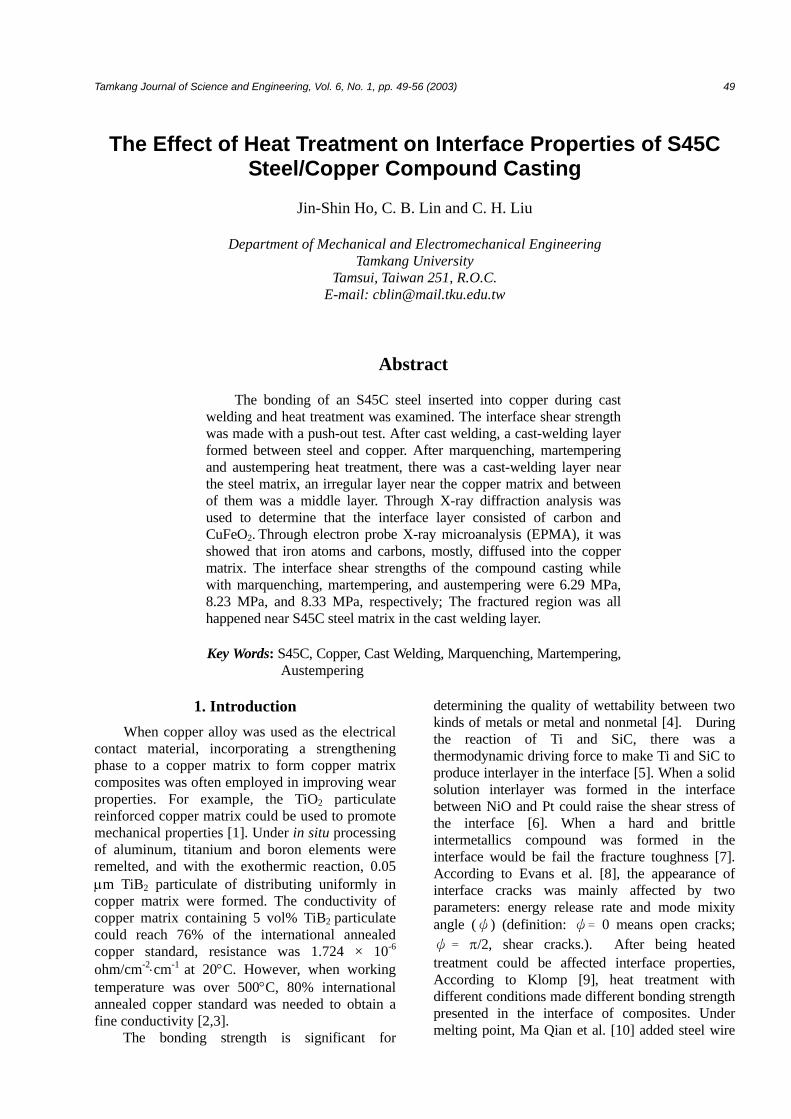
Figure 1. Apparatus for cast welding and compound
casting, (a) the upper sand mold; (b) the lower sand mold; (c) S45C/copper compound casting
of steel during whole cast welding procedure. Figure 1 shows the apparatus of cast welding and the compound casting.
2.2 Heat Treatment
The compound casting was cut into specimens with a 20 mm diameter and a 15 mm thickness, pre-heated to 800 °C ± 3 °C, and then isother- mally heated for two hours. Afterward, three heat treatments were used in this work. They are marquenching [cooling by stirring in (330 °C ±
10 °C; MS point) 50% NaNO2 + 50% KNO2 bath for 90 seconds, and then air-cooling to room temperature], martempering [cooling by stirring in (220 °C ± 10 °C at MS~Mf point) 50% NaNO2 + 50% KNO2 bath for 24 hrs, and then air-cooling to room temperature], and austempering [by stirring in (400 °C ± 10 °C) 50% NaNO2 + 50% KNO2 bath for 30 mins, and then air-cooling to room temperature].
riser runner
The upper sand mold
gate
The lower sand mold
Cavity
S45C/copper compound casting
The Effect of Heat Treatment on Interface Properties of S45C Steel/Copper Compound Casting 51
2.3 Microstructure Observation
The cut cross section of heat treated compound casting was ground by the carbimet paper of 100 grit to 1200 grit, polished by a suspension liquid of 0.3 µm Al2O3 particulate, and etched by an etching solution (95% ethanol + 5% nitric acid) for 3 seconds. Then, through OPTIPHOT-100 Nikon OM and JEOL-JSM 840A SEM, the microstructure of S45C steel, copper and interface were observed. Moreover, the relative proportion of iron to copper in the interface was analyzed through the line scan of JEOL JXA- 8800M EPMA.
Interface formed after cast welding and heat- treating was taken out to be ground into powder for X-ray diffraction analysis. A MAC Science MXP-3TXT-A104 X-ray diffraction analyzer with a copper-target was used at the speed of 4°/min.
2.4 Push Out Test
The testing rig for the push out tests consisted of an SKD11 (HRC62) tool steel lower plate with a 10.2 mm diameter hole. A 250 mm thick disk from the heat-treated compound casting was placed on the plate, and a 9.8 mm diameter SKD11 (HRC62) tool steel punch was used to push out the S45C steel insert. After the testing rig performed on an Instron testing machine, S45C steel of compound casting
was pushed out at the crosshead speed of 5mm/min and average of the interface shear strength was determined from three selected data.
2.5 Fracture Morphology Observation
Through an OPTIPHOT-100 Nikon OM, the fracture morphology of the pushed-out specimen was observed. Besides, the fracture morphology of the interface around being fractured could not be observed through OM until the specimen was polished and etched before push-out testing.
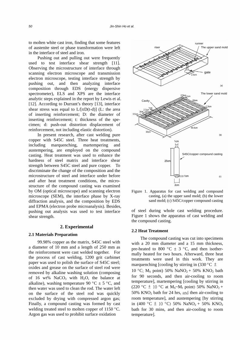
3. Results and Discussion The microstructure of cast welded S45C steel
with copper was shown in Figure 2(a). A cast-welding layer has been formed between steel and copper. This is because the 1150 °C molten copper was cast welded directly with steel to form the reacting layer while it was poured into the pre-heated sand mold after marquenching, mar- tempering, and austempering were used on the compound casting, its interface could be mainly divided into three sections: (I) The section closest to the S45C steel is called cast-welding layer, (II) the layer closest to the copper was an irregular layer, and (III) the last layer in between was middle layer, as shown in Figure 2(b) to Figure 2(d).
Figure 2. SEM morphology of S45C steel/copper compound casting, (a) before heated treatment; (b) marquenching; (c)
martempering; (d) austempering
52 Jin-Shin Ho et al.
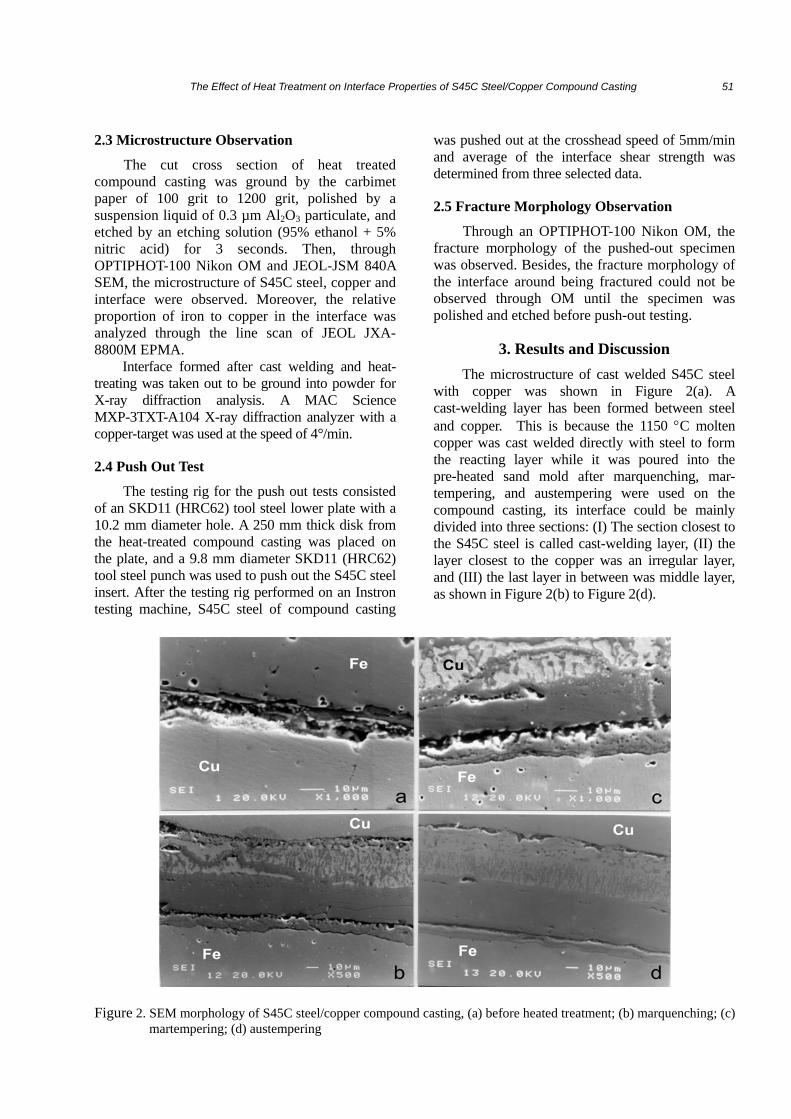
The microstructure of S45C steel after marquenching was mixed with quenched mar- tensite, carbides and retained austensite phase was shown in Figure 3 (a). After martempering, the microstructure is mixed with tempered martensite, lowers bainite and retained austensite phase, as shown in Figure 3 (b). After austempering, the microstructure is mixed with upper bainite, car- bides and retained austensite phase, as shown in Figure 3 (c).
Figure 3. SEM morphology of S45C steel matrix, (a) marquenching; (b) martempering; (c) aus- tempering
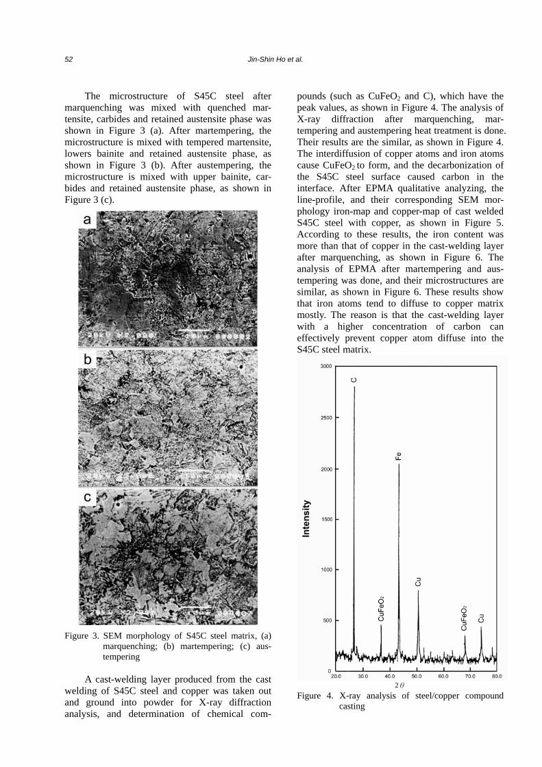
A cast-welding layer produced from the cast
welding of S45C steel and copper was taken out and ground into powder for X-ray diffraction analysis, and determination of chemical com-
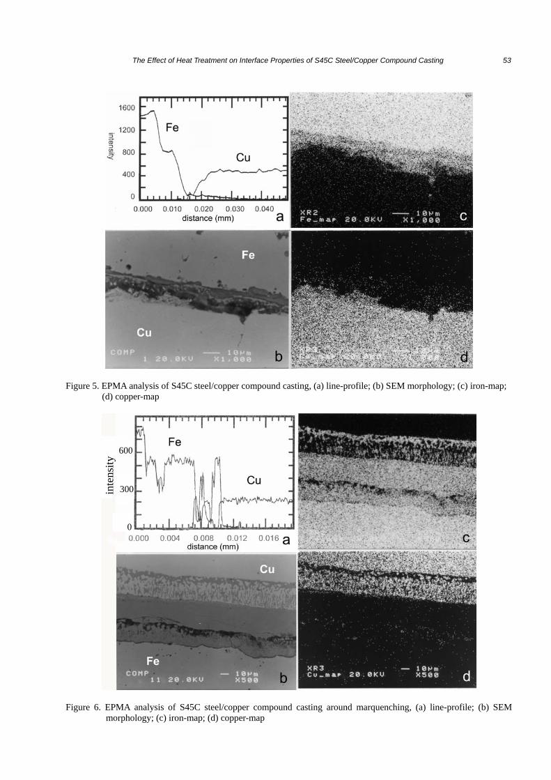
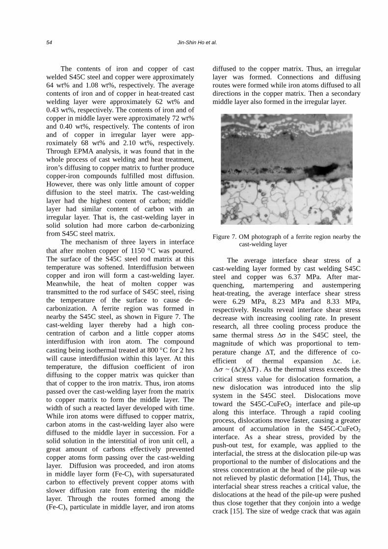
pounds (such as CuFeO2 and C), which have the peak values, as shown in Figure 4. The analysis of X-ray diffraction after marquenching, mar- tempering and austempering heat treatment is done. Their results are the similar, as shown in Figure 4. The interdiffusion of copper atoms and iron atoms cause CuFeO2 to form, and the decarbonization of the S45C steel surface caused carbon in the interface. After EPMA qualitative analyzing, the line-profile, and their corresponding SEM mor- phology iron-map and copper-map of cast welded S45C steel with copper, as shown in Figure 5. According to these results, the iron content was more than that of copper in the cast-welding layer after marquenching, as shown in Figure 6. The analysis of EPMA after martempering and aus- tempering was done, and their microstructures are similar, as shown in Figure 6. These results show that iron atoms tend to diffuse to copper matrix mostly. The reason is that the cast-welding layer with a higher concentration of carbon can effectively prevent copper atom diffuse into the S45C steel matrix.
2θ
Figure 4. X-ray analysis of steel/copper compound casting
The Effect of Heat Treatment on Interface Properties of S45C Steel/Copper Compound Casting 53
Figure 5. EPMA analysis of S45C steel/copper compound casting, (a) line-profile; (b) SEM morphology; (c) iron-map;
(d) copper-map
Figure 6. EPMA analysis of S45C steel/copper compound casting around marquenching, (a) line-profile; (b) SEM
morphology; (c) iron-map; (d) copper-map
inte
nsity
600
300
0
54 Jin-Shin Ho et al.
The contents of iron and copper of cast welded S45C steel and copper were approximately 64 wt% and 1.08 wt%, respectively. The average contents of iron and of copper in heat-treated cast welding layer were approximately 62 wt% and 0.43 wt%, respectively. The contents of iron and of copper in middle layer were approximately 72 wt% and 0.40 wt%, respectively. The contents of iron and of copper in irregular layer were app- roximately 68 wt% and 2.10 wt%, respectively. Through EPMA analysis, it was found that in the whole process of cast welding and heat treatment, iron’s diffusing to copper matrix to further produce copper-iron compounds fulfilled most diffusion. However, there was only little amount of copper diffusion to the steel matrix. The cast-welding layer had the highest content of carbon; middle layer had similar content of carbon with an irregular layer. That is, the cast-welding layer in solid solution had more carbon de-carbonizing from S45C steel matrix.
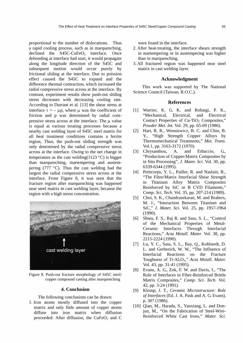
The mechanism of three layers in interface that after molten copper of 1150 °C was poured. The surface of the S45C steel rod matrix at this temperature was softened. Interdiffusion between copper and iron will form a cast-welding layer. Meanwhile, the heat of molten copper was transmitted to the rod surface of S45C steel, rising the temperature of the surface to cause de- carbonization. A ferrite region was formed in nearby the S45C steel, as shown in Figure 7. The cast-welding layer thereby had a high con- centration of carbon and a little copper atoms interdiffusion with iron atom. The compound casting being isothermal treated at 800 °C for 2 hrs will cause interdiffusion within this layer. At this temperature, the diffusion coefficient of iron diffusing to the copper matrix was quicker than that of copper to the iron matrix. Thus, iron atoms passed over the cast-welding layer from the matrix to copper matrix to form the middle layer. The width of such a reacted layer developed with time. While iron atoms were diffused to copper matrix, carbon atoms in the cast-welding layer also were diffused to the middle layer in succession. For a solid solution in the interstitial of iron unit cell, a great amount of carbons effectively prevented copper atoms form passing over the cast-welding layer. Diffusion was proceeded, and iron atoms in middle layer form (Fe-C)x with supersaturated carbon to effectively prevent copper atoms with slower diffusion rate from entering the middle layer. Through the routes formed among the (Fe-C)x particulate in middle layer, and iron atoms
diffused to the copper matrix. Thus, an irregular layer was formed. Connections and diffusing routes were formed while iron atoms diffused to all directions in the copper matrix. Then a secondary middle layer also formed in the irregular layer.
Figure 7. OM photograph of a ferrite region nearby the cast-welding layer
The average interface shear stress of a
cast-welding layer formed by cast welding S45C steel and copper was 6.37 MPa. After mar- quenching, martempering and austempering heat-treating, the average interface shear stress were 6.29 MPa, 8.23 MPa and 8.33 MPa, respectively. Results reveal interface shear stress decrease with increasing cooling rate. In present research, all three cooling process produce the same thermal stress ∆σ in the S45C steel, the magnitude of which was proportional to tem- perature change ∆T, and the difference of co- efficient of thermal expansion ∆c. i.e.
))((~ Tc ∆∆∆σ . As the thermal stress exceeds the critical stress value for dislocation formation, a new dislocation was introduced into the slip system in the S45C steel. Dislocations move toward the S45C-CuFeO2 interface and pile-up along this interface. Through a rapid cooling process, dislocations move faster, causing a greater amount of accumulation in the S45C-CuFeO2 interface. As a shear stress, provided by the push-out test, for example, was applied to the interfacial, the stress at the dislocation pile-up was proportional to the number of dislocations and the stress concentration at the head of the pile-up was not relieved by plastic deformation [14], Thus, the interfacial shear stress reaches a critical value, the dislocations at the head of the pile-up were pushed thus close together that they conjoin into a wedge crack [15]. The size of wedge crack that was again
The Effect of Heat Treatment on Interface Properties of S45C Steel/Copper Compound Casting 55
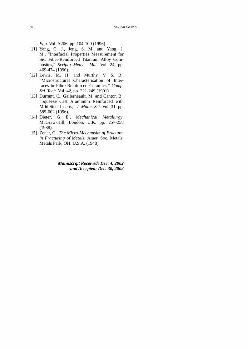
proportional to the number of dislocations. Thus a rapid cooling process, such as in marquenching, declined the S45C-CuFeO2 interface. Once debonding at interface had start, it would propagate along the longitude direction of the S45C and subsequent motion would occur purely by frictional sliding at the interface. Due to poission effect caused the S45C to expand and the difference thermal contraction, which increased the radial compressive stress across at the interface. By contrast, experiment results show push-out sliding stress decreases with decreasing cooling rate. According to Durrant et al. [13] the shear stress at interface τ = − µp, where µ was the coefficient of friction and p was determined by radial com- pressive stress across at the interface. The µ value is equal at various treating processes because a nearby cast welding layer of S45C steel matrix for all heat treatment conditions contains a ferrite region, Thus, the push-out sliding strength was only determined by the radial compressive stress across at the interface. Owing to the net change in temperature as the cast welding(1123 °C) is bigger than marquenching, martempering and austem- pering (777 °C). Thus the cast welding had the largest the radial compressive stress across at the interface. From Figure 8, it was seen that the fracture region after marquenching was happened near steel matrix in cast welding layer, because the region with a high stress concentration.
Figure 8. Push-out fracture morphology of S45C steel/
copper compound casting after marquenching
4. Conclusion The following conclusions can be drawn:
1. Iron atoms mostly diffused into the copper matrix and only little amount of copper atoms diffuse into iron matrix when diffusion proceeded. After diffusion, the CuFeO2 and C
were found in the interface. 2. After heat-treating, the interface shears strength
in martempering or in austempering was higher than in marquenching.
3. All fractured region was happened near steel matrix in cast welding layer.
Acknowledgment This work was supported by The National
Science Council (Taiwan, R.O.C.).
References [1] Warrier, K. G. K. and Rohatgi, P. K.,
“Mechanical, Electrical, and Electrical Contact Properties of Cu-TiO2 Composites,” Powder Met. Int. Vol. 29, pp. 65-69 (1986).
[2] Hart, R. R., Wonsiewicz, B. C. and Chin, B. Y., “High Strength Copper Alloys by Thermomechanical Treatments,” Met. Trans. Vol.1, pp. 3163-3172 (1970).
[3] Chrysanthou, A. and Erbaccio, G., “Production of Copper-Matrix Composites by in Situ Processing”, J. Mater. Sci. Vol. 30, pp. 6339-6344 (1995).
[4] Petitcorps, Y. L., Pailler, R. and Naslain, R., “The Fibre/Matrix Interfacial Shear Strength in Titanium Alloy Matrix Composites Reinforced by SiC or B CVD Filaments,” Comp. Sci. Tech. Vol. 35, pp. 207-214 (1989).
[5] Choi, S. K., Chandrasekaran, M. and Brabers, M. J., “Interaction Between Titanium and SiC,” J. Mater. Sci. Vol. 25, pp. 1957-1964 (1990).
[6] Shieu, F. S., Raj R. and Sass, S. L., “Control of the Mechanical Properties of Metal- Ceramic Interfaces Through Interfacial Reactions,” Acta Metall. Mater. Vol. 38, pp. 2215-2224 (1990).
[7] Lu, Y. C., Sass, S. L., Bay, Q., Kohlstedt, D. L. and Gerberich, W. W., “The Influence of Interfacial Reactions on the Fracture Toughness of Ti-Al2O3,” Acta Metall. Mater. Vol. 43, pp. 31-41 (1995).
[8] Evans, A. G., Zok, F. W. and Davis, I., “The Role of Interfaces in Fiber-Reinforced Brittle Matrix Composites,” Comp. Sci. Tech. Vol. 42, pp. 3-24 (1991).
[9] Klomp, J. T., Ceramic Microstructure: Role of Interfaces (Ed. J. A. Pask and A. G. Evans), p. 307 (1986).
[10] Qian, M., Harada, S., Yanxiang, L. and Don- jun, M., “On the Fabrication of Steel-Wire- Reinforced White Cast Irons,” Mater. Sci.
56 Jin-Shin Ho et al.
Eng. Vol. A206, pp. 104-109 (1996). [11] Yang, C. J., Jeng, S. M. and Yang, J.
M., ”Interfacial Properties Measurement for SiC Fiber-Reinforced Titanium Alloy Com- posites,” Scripta Meter. Mat. Vol. 24, pp. 469-474 (1990).
[12] Lewis, M. H. and Murthy, V. S. R., “Microstructural Characterisation of Inter- faces in Fibre-Reinforced Ceramics,” Comp. Sci. Tech. Vol. 42, pp. 221-249 (1991).
[13] Durrant, G., Gallerneault, M. and Cantor, B., “Squeeze Cast Aluminum Reinforced with Mild Steel Inserts,” J. Mater. Sci. Vol. 31, pp. 589-602 (1996).
[14] Dieter, G. E., Mechanical Metallurgy, McGraw-Hill, London, U.K. pp. 257-258 (1988).
[15] Zener, C., The Micro-Mechansim of Fracture, in Fracturing of Metals, Amer. Soc. Metals, Metals Park, OH, U.S.A. (1948).
Manuscript Received: Dec. 4, 2002 and Accepted: Dec. 30, 2002