The Effect of Alluvial Foundation on the Earth Dams...
15
Open Journal of Geology, 2017, 7, 360-373 http://www.scirp.org/journal/ojg ISSN Online: 2161-7589 ISSN Print: 2161-7570 DOI: 10.4236/ojg.2017.73025 March 30, 2017 The Effect of Alluvial Foundation on the Earth Dams Settlement Masoud Ghaemi 1 , Kaveh Ahangari 1* , Ali Noorzad 2 , Kamran Goshtasbi 3 1 Department of Mining Engineering, Science and Research Branch, Islamic Azad University, Tehran, Iran 2 Faculty of Water and Environmental Engineering, Shahid Beheshti University, Tehran, Iran 3 Faculty of Mining Engineering, Tarbiat Modares University, Tehran, Iran Abstract Careful monitoring in the earth dams, to measure deformation caused by set- tlement and movement has always been a concern for engineers in the field. In order to measure settlement and deformation of earth dams, usually the precision instruments of settlement set and combined Inclinometer that is commonly referred to IS instrument, will be used. In some dams, because the thickness of alluvium is high and there is no possibility of alluvium removal (technically and economically and in terms of performance), there is no pos- sibility to place the end of IS instrument (precision instruments of Inclinome- ter-settlement set) in the rock foundation. Inevitably, have to accept installing pipes in the weak and the deformable alluvial foundation that this leads to er- rors in the calculation of the actual settlement (absolute settlement) in differ- ent parts of the dam body. The purpose of this paper is to present new and re- fine criteria for predicting settlement and deformation in earth dams. The study is based on conditions in three dams with a deformation quite alluvial (Agh Chai, Narmashir and Gilan-e Gharb) to provide settlement criteria af- fected by alluvial foundation. To achieve this goal, the settlement of dams was simulated by using finite difference method with FLAC3D software and then the modeling results were compared with reading IS instrument. In the end, the caliber of the model and validate the results, by using regression analysis techniques and scrutinized modeling parameters with real situations and then by using MATLAB software and Curve Fitting Toolbox, a new criteria for the settlement based on elasticity modulus, cohesion, friction angle, density of earth dam and alluvial foundation was obtained. The results of these studies show that, by using the new criteria measures, the amount of settlement and deformation for the dams with alluvial foundation can be corrected after in- strument readings and the error rate in reading IS instrument can be greatly reduced. How to cite this paper: Ghaemi, M., Ahangari, K., Noorzad, A. and Goshtasbi, K. (2017) The Effect of Alluvial Foundation on the Earth Dams Settlement. Open Jour- nal of Geology, 7, 360-373. https://doi.org/10.4236/ojg.2017.73025 Received: January 9, 2017 Accepted: March 27, 2017 Published: March 30, 2017 Copyright © 2017 by authors and Scientific Research Publishing Inc. This work is licensed under the Creative Commons Attribution International License (CC BY 4.0). http://creativecommons.org/licenses/by/4.0/ Open Access
Transcript of The Effect of Alluvial Foundation on the Earth Dams...
Open Journal of Geology, 2017, 7, 360-373 http://www.scirp.org/journal/ojg
ISSN Online: 2161-7589 ISSN Print: 2161-7570
DOI: 10.4236/ojg.2017.73025 March 30, 2017
The Effect of Alluvial Foundation on the Earth Dams Settlement
Masoud Ghaemi1, Kaveh Ahangari1*, Ali Noorzad2, Kamran Goshtasbi3
1Department of Mining Engineering, Science and Research Branch, Islamic Azad University, Tehran, Iran 2Faculty of Water and Environmental Engineering, Shahid Beheshti University, Tehran, Iran 3Faculty of Mining Engineering, Tarbiat Modares University, Tehran, Iran
Abstract Careful monitoring in the earth dams, to measure deformation caused by set-tlement and movement has always been a concern for engineers in the field. In order to measure settlement and deformation of earth dams, usually the precision instruments of settlement set and combined Inclinometer that is commonly referred to IS instrument, will be used. In some dams, because the thickness of alluvium is high and there is no possibility of alluvium removal (technically and economically and in terms of performance), there is no pos-sibility to place the end of IS instrument (precision instruments of Inclinome-ter-settlement set) in the rock foundation. Inevitably, have to accept installing pipes in the weak and the deformable alluvial foundation that this leads to er-rors in the calculation of the actual settlement (absolute settlement) in differ-ent parts of the dam body. The purpose of this paper is to present new and re-fine criteria for predicting settlement and deformation in earth dams. The study is based on conditions in three dams with a deformation quite alluvial (Agh Chai, Narmashir and Gilan-e Gharb) to provide settlement criteria af-fected by alluvial foundation. To achieve this goal, the settlement of dams was simulated by using finite difference method with FLAC3D software and then the modeling results were compared with reading IS instrument. In the end, the caliber of the model and validate the results, by using regression analysis techniques and scrutinized modeling parameters with real situations and then by using MATLAB software and Curve Fitting Toolbox, a new criteria for the settlement based on elasticity modulus, cohesion, friction angle, density of earth dam and alluvial foundation was obtained. The results of these studies show that, by using the new criteria measures, the amount of settlement and deformation for the dams with alluvial foundation can be corrected after in-strument readings and the error rate in reading IS instrument can be greatly reduced.
How to cite this paper: Ghaemi, M., Ahangari, K., Noorzad, A. and Goshtasbi, K. (2017) The Effect of Alluvial Foundation on the Earth Dams Settlement. Open Jour-nal of Geology, 7, 360-373. https://doi.org/10.4236/ojg.2017.73025 Received: January 9, 2017 Accepted: March 27, 2017 Published: March 30, 2017 Copyright © 2017 by authors and Scientific Research Publishing Inc. This work is licensed under the Creative Commons Attribution International License (CC BY 4.0). http://creativecommons.org/licenses/by/4.0/
Open Access
M. Ghaemi et al.
361
Keywords Earth Dam, Alluvial Foundation, Settlement, Finite Difference, FLAC3D, MATLAB, Curve Fitting, Refine Criteria, IS Instrument
1. Introduction
There are always parameters in the design of earth dams that are considered the leading cause of dam design, including leakage, settlement, and permeability, type of spillway and dynamic resistance of the dam are considered the important parameters of the dam [1].
Perhaps it can be said that among aforementioned parameters, the importance of settlement and deformation is an important factor in the behavior of the dam during construction, impounding dam and in operational stage. In order to measure settlement and horizontal deformation of dams usually the precision instruments of settlement set and combined Inclinometer that is commonly re-ferred to IS instrument, will be used [2]. Installing IS instrument (Inclinometer- settlement set) in the rock foundation of earth dams with alluvial layers in fixed point or in other words, to determine the point at which the movement or de-formation of the pipes will be zero in it, is very difficult. In terms of another, be-cause of the correct placement of IS instrument in the bedrock, the results are always relative; however, it is necessary to compare this reading with the base magnet to analyze settlement set reading. This question has also been raised that what is the appropriate criteria for the results of IS pipe, according to the differ-ent physical characteristics in the alluvial layers of dam foundation.
Many researchers and engineers have suggested different methods to analyze the settlement and horizontal deformation of the dam and they have divided them into five general groups that include: 1) numerically; 2) the experimental method; 3) instrumentation; 4) micro geodesy; 5) smart methods (Fuzzy Net-work, Neural Network, Genetic Algoritm [3]. Chrzanowski carried out the de-velopment of the first research on the analysis of the earth dam deformation. In mentioning research, the transformations were more considered caused by the stresses imposed on the dam body [4]. Kelaf, et al. were the first people that modeled an earthen dam in 1997 by using finite element method. He calculated the stress and strain in a gravel dam by using linear elastic behavior model [5].
Then Duncan, et al. in 1997 presented a few papers and introduced nonlinear hyperbolic model, a new behavioral model for settlement and deformation anal-ysis of earth dams. [6] In their results, they indicated that the behavioral model provides results that are more realistic [7].
Marandi, M., et al., in 2012, tried to estimate the extent of settlement in dam crest by using GEP. They have studied on 30 dams in seven countries. The re-sults showed that the method of GEP is able to estimate the dam crest settlement based on four characteristics: the porosity of the dam e, height H, vertical de-formation modulus Ev and shape factor Sc [8].

M. Ghaemi et al.
362
In this regards, in this paper, first the evaluation and case studies of Geo-me- chanical parameters will be discussed. After explaining the modeling and its steps in FLAC3D software, the settlement plots, and initial analysis of dams will be shown based on three intended history points, which respectively, include M1 (dam bottom), M2 (one third of the dam body height) and M3 (two thirds of the dam body height). In the following, preliminary modeling results will be com-pared with the instrumentation results of IS instrument and in the next step, af-ter determining the deviation parameters for numerical modeling, modeling pa-rameters will be reviewed by using back analysis technique. Finally, by using the MATLAB and Curve Fitting Toolbox [9], a new equation will be presented for correction values settlement of earth dam, with alluvial foundation, based on the basic parameters of the earth dams [10].
2. Evaluation of Case Studies
As it was mentioned earlier, in this article, three case studies have been used to determine the criteria measures, that by modeling, it is included Agh Chai Dam, [11] Narmashir dam and Gilan-e Gharb dam. In addition, the main specifica-tions of all three dams have been briefly brought in Table 1. In addition, plan and longitudinal sections of all three dams have been respectively brought [12].
3. Modeling Earth Dam and Foundation 3.1. Modeling Process
In this part, modeling and the process are generally examined. According to the principles of numerical modeling as well as the fact dam, the dam model-ing of Agh Chai, Narmashir and Gilan-e Gharb with Flac 3D program is as follows:
1) Determining the size, scope and number of meshes in dam geometry mod-eling;
2) Assign materials to different parts of the model (alluvium, foundation and the dam body);
Table 1. Main Specifications of Agh Chai dam, Narmashir dam and Gilan-e Gharb [10] [11] [12].
Gilan-e Gharb dam
Narmashir dam
Agh Chai dam Project name
Specifications
Earth dam Rockfill dam Arch dam
embankment Type of dam
60 108.5 111.5 Dam height (m)
610 720 1240 X length of dam (m)
9 16 19 The dam crest width (m)
5 7.9 9.3 Embankment volume (million cubic meters)
21.5 32 25 Maximum thickness of alluvium (m)
2002 2004 2005 Construction time

M. Ghaemi et al.
363
3) Reticulation of dam body, alluvial foundation and bedrock by 15 node tri-angular elements (plane strain condition);
4) Apply static initial and boundary conditions; 5) Create the initial stresses in foundation and alluvium dam; 6) Allocation and defining gravity; 7) Solving the model to achieve a basic balance; 8) Fix the displacement and speed in knots; 9) Construction of the dam body and overall solution to the stable conditions.
3.2. Geomechanical Properties of Earth Dam
In this part, the geomechanical properties of the earth dam, alluvial foundation and bedrock components have been surveyed, given the prevailing sandy texture and low clay content and rock foundation in the main specifications are in Tables 2-6 below. Table 2. Geotechnical properties of components AghChay dam, Narmashir and Gilan-e Gharb [10] [11] [12].
Specifications Components of dam
Dam name Parameter unit Core Crust
AghChay
Particularly dry weight dry kN/m3 17 21
Special saturated weight sat kN/m3 18 22 Permeability k cm/s 10 - 6 10 - 3
Cohesion C kPa 28 1 Angle of friction deg 25 42
Narmashir
Particularly dry weight dry kN/m3 16 22
Special saturated weight sat kN/m3 18 24
Permeability k cm/s 10 - 7 10 - 3 Cohesion C kPa 30 1.5
Angle of friction deg 28 39
Gilan-e Gharb
Particularly dry weight dry kN/m3 15 24
Special saturated weight sat kN/m3 16 25
Permeability k cm/s 10 - 8 10 - 3
Cohesion C kPa 28 1
Angle of friction deg 25 42
Table 3. The shear and bulk modulus in Agh Chai Dam, Narmashir and Gilan-e Gharb [10] [11] [12].
Specifications Components of dam
Dam name Parameter unit Core Crust
AghChay Gm0 MPa 115 185
K MPa 560 440
Narmashir Gm0 MPa 125 170
K MPa 550 410
Gilan-e Gharb Gm0 MPa 110 190
K MPa 620 515

M. Ghaemi et al.
364
Table 4. The Geotechnical properties of alluvial foundation in the Agh Chai dam [10].
Specifications Depth (m)
Parameter Unit 0 - 5 5 - 10 10 - 15 15 - 25
Special weight kN/m3 17 18 19 19
Relative density % 62 65 74 81
The initial shear modulus MPa 65 87 110 140
Shear modulus (after construction of the dam)
MPa 98 110 145 170
Bulk modulus MPa 115 190 235 410
Permeability cm/s 10 - 3 10 - 3 10 - 3 10 - 3
Cohesion kPa 0 0 0 0
Angle of friction deg. 29 33 33 35
Table 5. The Geotechnical properties of alluvial foundation in the Narmashir dam [11].
Specifications Depth (m)
Parameter Unit 0 - 10 10 - 20 20 - 30 30 - 32
Special weight kN/m3 14 16 17 18
Relative density % 56 60 70 77
The initial shear modulus MPa 92 98 124 155
Shear modulus (after construction of the dam)
MPa 151 151 182 195
Bulk modulus MPa 190 230 440 520
Permeability cm/s 10 - 3 10 - 3 10 - 3 10 - 3
Cohesion kPa 0 0 0 0
Angle of friction deg. 24 25 27 31
Table 6. The Geotechnical properties of alluvial foundation in the Gilan-e Gharb dam [12].
Specifications Depth (m)
Parameter Unit 0 - 5 5 - 10 10 - 15 15 - 22
Special weight KN/m3 13 14 14 15
Relative density % 48 52 55 58
The initial shear modulus MPa 80 87 110 142
Shear modulus (after construction of the dam)
MPa 145 160 178 190
Bulk modulus MPa 160 210 300 350
Permeability cm/s 10 - 3 10 - 3 10 - 3 10 - 3
Cohesion kPa 0 0 0 0
Angle of friction deg. 30 30 33 33
To model the dam body, every three dams, along with alluvial foundation and
bedrock have taken place as an effective stress analysis, together with analysis of consolidation. It should be noted that, for three-dimensional modeling of all three dams, Fish functions in software FLAC3D was used and a complete coding
M. Ghaemi et al.
365
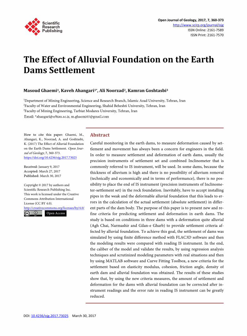
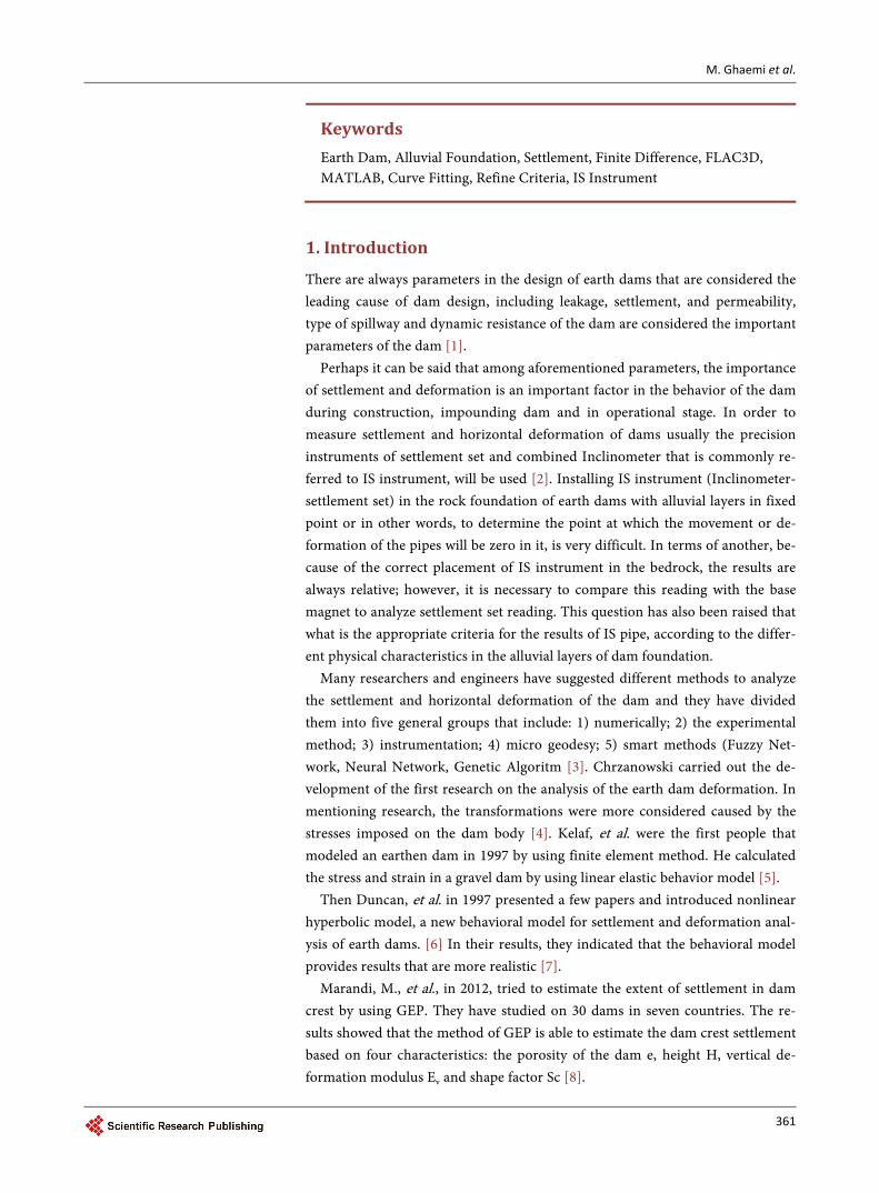
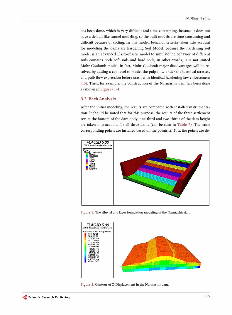
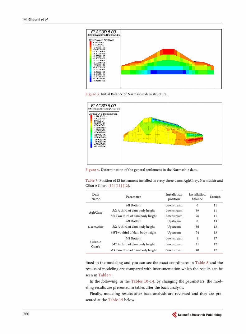
has been done, which is very difficult and time-consuming, because it does not have a default like tunnel modeling, so the built models are time-consuming and difficult because of coding. In this model, behavior criteria taken into account for modeling the dams are hardening Soil Model, because the hardening soil model is an advanced Elasto-plastic model to simulate the behavior of different soils contains both soft soils and hard soils, in other words, it is not-united Mohr-Coulomb model. In fact, Mohr-Coulomb major disadvantages will be re-solved by adding a cap level to model the pulp flow under the identical stresses, and pulb flow expression before crash with identical hardening law enforcement [13]. Then, for example, the construction of the Narmashir dam has been done as shown in Figures 1-4.
3.3. Back Analysis
After the initial modeling, the results are compared with installed instrumenta-tion. It should be noted that for this purpose, the results of the three settlement sets at the bottom of the dam body, one-third and two-thirds of the dam height are taken into account for all three dams (can be seen in Table 7). The same corresponding points are installed based on the points X, Y, Z, the points are de-
Figure 1. The alluvial and layer foundation modeling of the Narmashir dam.
Figure 2. Contour of Z-Displacement in the Narmashir dam.
M. Ghaemi et al.
366
Figure 3. Initial Balance of Narmashir dam structure.
Figure 4. Determination of the general settlement in the Narmashir dam. Table 7. Position of IS instrument installed in every three dams AghChay, Narmashir and Gilan-e Gharb [10] [11] [12].
Dam Name
Parameter Installation
position Installation
balance Section
AghChay
M1 Bottom downstream 0 11 M2 A third of dam body height downstream 39 11
M3 Two third of dam body height downstream 76 11
Narmashir
M1 Bottom Upstream 0 13
M2 A third of dam body height Upstream 36 13
M3Two third of dam body height Upstream 74 13
Gilan-e Gharb
M1 Bottom downstream 1 17
M2 A third of dam body height downstream 21 17
M3 Two third of dam body height downstream 40 17
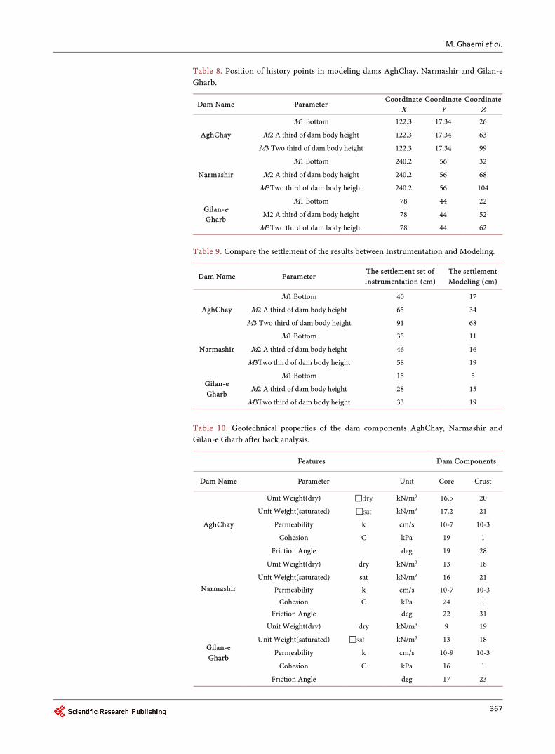
fined in the modeling and you can see the exact coordinates in Table 8 and the results of modeling are compared with instrumentation which the results can be seen in Table 9.
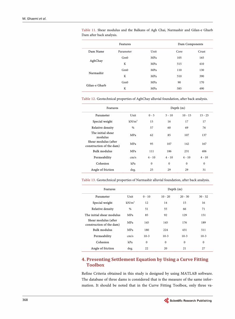
In the following, in the Tables 10-14, by changing the parameters, the mod-eling results are presented in tables after the back analysis.
Finally, modeling results after back analysis are reviewed and they are pre-sented at the Table 15 below.
M. Ghaemi et al.
367
Table 8. Position of history points in modeling dams AghChay, Narmashir and Gilan-e Gharb.
Dam Name Parameter Coordinate
X Coordinate
Y Coordinate
Z
AghChay
M1 Bottom 122.3 17.34 26
M2 A third of dam body height 122.3 17.34 63
M3 Two third of dam body height 122.3 17.34 99
Narmashir
M1 Bottom 240.2 56 32
M2 A third of dam body height 240.2 56 68
M3Two third of dam body height 240.2 56 104
Gilan-e Gharb
M1 Bottom 78 44 22
M2 A third of dam body height 78 44 52
M3Two third of dam body height 78 44 62
Table 9. Compare the settlement of the results between Instrumentation and Modeling.
Dam Name Parameter The settlement set of Instrumentation (cm)
The settlement Modeling (cm)
AghChay
M1 Bottom 40 17
M2 A third of dam body height 65 34
M3 Two third of dam body height 91 68
Narmashir
M1 Bottom 35 11
M2 A third of dam body height 46 16
M3Two third of dam body height 58 19
Gilan-e Gharb
M1 Bottom 15 5
M2 A third of dam body height 28 15
M3Two third of dam body height 33 19
Table 10. Geotechnical properties of the dam components AghChay, Narmashir and Gilan-e Gharb after back analysis.
Features Dam Components
Dam Name Parameter Unit Core Crust
AghChay
Unit Weight(dry) dry kN/m3 16.5 20
Unit Weight(saturated) sat kN/m3 17.2 21
Permeability k cm/s 10-7 10-3
Cohesion C kPa 19 1
Friction Angle deg 19 28
Narmashir
Unit Weight(dry) dry kN/m3 13 18
Unit Weight(saturated) sat kN/m3 16 21
Permeability k cm/s 10-7 10-3 Cohesion C kPa 24 1
Friction Angle deg 22 31
Gilan-e Gharb
Unit Weight(dry) dry kN/m3 9 19
Unit Weight(saturated) sat kN/m3 13 18
Permeability k cm/s 10-9 10-3
Cohesion C kPa 16 1
Friction Angle deg 17 23
M. Ghaemi et al.
368
Table 11. Shear modulus and the Balkans of Agh Chai, Narmashir and Gilan-e Gharb Dam after back analysis.
Features Dam Components
Dam Name Parameter Unit Core Crust
AghChay Gm0 MPa 105 165
K MPa 515 410
Narmashir Gm0 MPa 110 130
K MPa 510 390
Gilan-e Gharb Gm0 MPa 90 170
K MPa 585 490
Table 12. Geotechnical properties of AghChay alluvial foundation, after back analysis.
Features Depth (m)
Parameter Unit 0 - 5 5 - 10 10 - 15 15 - 25
Special weight kN/m3 15 16 17 17
Relative density % 57 60 69 76
The initial shear modulus
MPa 62 85 107 137
Shear modulus (after construction of the dam)
MPa 95 107 142 167
Bulk modulus MPa 111 186 231 406
Permeability cm/s 4 - 10 4 - 10 4 - 10 4 - 10
Cohesion kPa 0 0 0 0
Angle of friction deg. 25 29 29 31
Table 13. Geotechnical properties of Narmashir alluvial foundation, after back analysis.
Features Depth (m)
Parameter Unit 0 - 10 10 - 20 20 - 30 30 - 32
Special weight kN/m3 12 14 15 16
Relative density % 51 55 66 71
The initial shear modulus MPa 85 92 129 151
Shear modulus (after construction of the dam)
MPa 145 145 176 189
Bulk modulus MPa 180 224 431 511
Permeability cm/s 10-3 10-3 10-3 10-3
Cohesion kPa 0 0 0 0
Angle of friction deg. 22 20 21 27
4. Presenting Settlement Equation by Using a Curve Fitting Toolbox
Refine Criteria obtained in this study is designed by using MATLAB software. The database of three dams is considered that is the measure of the same infor-mation. It should be noted that in the Curve Fitting Toolbox, only three va-
M. Ghaemi et al.
369
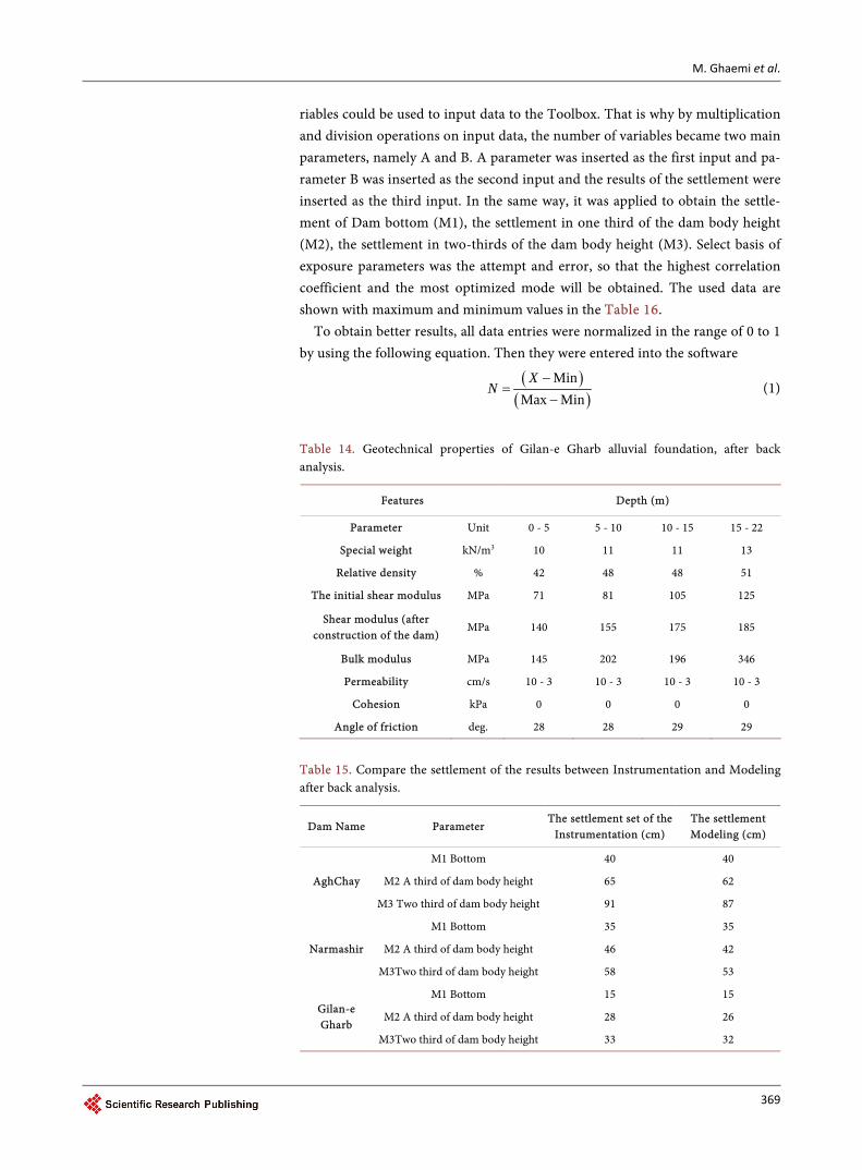
riables could be used to input data to the Toolbox. That is why by multiplication and division operations on input data, the number of variables became two main parameters, namely A and B. A parameter was inserted as the first input and pa-rameter B was inserted as the second input and the results of the settlement were inserted as the third input. In the same way, it was applied to obtain the settle-ment of Dam bottom (M1), the settlement in one third of the dam body height (M2), the settlement in two-thirds of the dam body height (M3). Select basis of exposure parameters was the attempt and error, so that the highest correlation coefficient and the most optimized mode will be obtained. The used data are shown with maximum and minimum values in the Table 16.
To obtain better results, all data entries were normalized in the range of 0 to 1 by using the following equation. Then they were entered into the software
( )( )
MinMax Min
XN
−=
− (1)
Table 14. Geotechnical properties of Gilan-e Gharb alluvial foundation, after back analysis.
Features Depth (m)
Parameter Unit 0 - 5 5 - 10 10 - 15 15 - 22
Special weight kN/m3 10 11 11 13
Relative density % 42 48 48 51
The initial shear modulus MPa 71 81 105 125
Shear modulus (after construction of the dam)
MPa 140 155 175 185
Bulk modulus MPa 145 202 196 346
Permeability cm/s 10 - 3 10 - 3 10 - 3 10 - 3
Cohesion kPa 0 0 0 0
Angle of friction deg. 28 28 29 29
Table 15. Compare the settlement of the results between Instrumentation and Modeling after back analysis.
Dam Name Parameter The settlement set of the
Instrumentation (cm) The settlement Modeling (cm)
AghChay
M1 Bottom 40 40
M2 A third of dam body height 65 62
M3 Two third of dam body height 91 87
Narmashir
M1 Bottom 35 35
M2 A third of dam body height 46 42
M3Two third of dam body height 58 53
Gilan-e Gharb
M1 Bottom 15 15
M2 A third of dam body height 28 26
M3Two third of dam body height 33 32
M. Ghaemi et al.
370
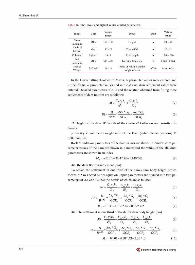
Table 16. The lowest and highest values of used parameters.
Input Unit Values range
Input Unit Values range
Shear modulus
MPa 160 - 100 Height m 180 - 90
Angle of friction
deg 50 - 20 Crest width m 22 - 12
Cohesion kg/cm2 18 - 1 Axial length m 1240 - 610 Bulk
modulus MPa 590 - 400 Porosity difference % 0.206 - 0.104
Special Weight
kN/m3 21 - 12 Ratio of volume, on the
weight of dam m3/ton 0-48 - 0.52
In the Curve Fitting Toolbox of X-axis, A parameter values were entered and
in the Y-axis, B parameter values and in the Z-axis, dam settlement values were entered. Detailed parameters of A, B and the relation obtained from fitting these settlements of dam Bottom are as follows:
1 f f f a a a
f a
C k C kA
γ γ= +
∅ ∅ (2)
* *1 *
*f f a a
f a
e G e GHBB OCR OCR
∆ ∆= +
∇ (3)
H: Height of the dam W: Width of the crown C: Cohesion Δe: porosity dif-ference
γ: density ∇: volume to weight ratio of the Dam (cubic meters per tons) K: bulk modulus
Rock foundation parameters of the dam values are shown in f index, core pa-rameter values of the dam are shown in c index and the values of the alluvium parameters are shown in an index
1 116.1 31.4* 1 1.149* 1M A B= − + + (4)
M1: the dam Bottom settlement (cm) To obtain the settlement in one third of the dam's dam body height, which
means M2 was acted as M1 equation; input parameters are divided into two pa-rameters of A2, and B2 that the details of which are as follows:
2 f f f a a a c c c
f a c
C k C k C kA
γ γ γ= + +
∅ ∅ ∅ (5)
* * *2 *
*f f a a c c
f a c
e G e G e GHBB OCR OCR OCR
∆ ∆ ∆= + +
∇ (6)
2 18.33 1.135* 2 0.85* 2M A B= − + (7)
M2: The settlement in one third of the dam’s dam body height (cm)
3 f f f a a a c c c s s s
f a c s
C k C k C k C kA
γ γ γ γ= + + +
∅ ∅ ∅ ∅ (8)
* * * *3 *
*f f a a c c s s
f a c s
e G e G e G e GHBB OCR OCR OCR OCR
∆ ∆ ∆ ∆= + + +
∇ (9)
3 64.01 4.38* 3 1.26* M A B= − + (10)
M. Ghaemi et al.
371
M3: The settlement in the point near the dam crest (cm) After calculating each prediction model, it is necessary to examine the ability
and the power of different forecasting models. There are diverse criteria for eva-luating the performance of different forecasting methods, however, in this study, to compare the prediction power, the average absolute error criteria, standard deviation, coefficient of determination and mean square error root are used in the Table 17. These criteria can be shown as Equations (11) to (14):
( )21
1 nii e e
n −=
=
∑σ (11)
1
1 ni iiMAE m p
n −=
=
∑ (12)
( )21
1 ni iiRMSE m p
n −=
=
∑ (13)
( )( )( ) ( )
2
2 12 2
1 1
ni ii
n ni ii i
p p m mR
p p m m=
= =
− − = − −
∑∑ ∑
(14)
Table 17 is according to the performance of the specified Equations in CURVE FITTING, which represents the accuracy and precision of equations. In addition, Table 17, will be taught based on the instrumentation information and it will calculate the errors in each equation.
5. Discussion
An equation is presented for dam’s settlement in three points of close to the crown, half of the dam body height and the dam’s bottom by using the collected data. Based on Equations 4, 7 and 10, dams’ settlement of Agh Chai, Narmashir and Gilan-e Gharb was amended and results are shown in Table 18.
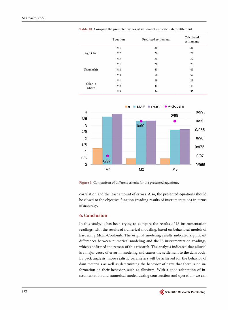
In addition, the results of performance obtained from the presented equations are shown in Figure 5 in comparison by using various criteria.
As network analysis results showed, the best correlation coefficient between the predicted settlement and settlement of instrumentation in the Curve Fitting of MATLAB software is related to the M1 equation. It should be noted that the correlation coefficient between the instrumentation and predicted values is ob-tained by all three equations as according to all the data. The proposed equa-tion can be used easily to estimate the settlement at minimum time for the dams with alluvium that with the use of it, the IS pipes readings can be cor-rected. To determine the amount of M1 and other proposed equations (M2 & M3), it is trying to present an equation by trial and error that has the highest
Table 17. The statistics range of best fitting.
RMSE Adjusted R-square R-square SSE
0.0323 0.986 0.987 0.038 M1
0.0963 0.864 0.8718 0.343 M2
0.044 0.961 0.963 0.073 M3
M. Ghaemi et al.
372
Table 18. Compare the predicted values of settlement and calculated settlement.
Equation Predicted settlement Calculated settlement
Agh Chai
M1 20 21
M2 26 27
M3 31 32
Narmashir
M1 28 29
M2 41 41
M3 56 57
Gilan-e Gharb
M1 29 29
M2 41 43
M3 54 55
Figure 5. Comparison of different criteria for the presented equations.
correlation and the least amount of errors. Also, the presented equations should be closed to the objective function (reading results of instrumentation) in terms of accuracy.
6. Conclusion
In this study, it has been trying to compare the results of IS instrumentation readings, with the results of numerical modeling, based on behavioral models of hardening Mohr-Coulomb. The original modeling results indicated significant differences between numerical modeling and the IS instrumentation readings, which confirmed the reason of this research. The analysis indicated that alluvial is a major cause of error in modeling and causes the settlement to the dam body. By back analysis, more realistic parameters will be achieved for the behavior of dam materials as well as determining the behavior of parts that there is no in-formation on their behavior, such as alluvium. With a good adaptation of in-strumentation and numerical model, during construction and operation, we can
M. Ghaemi et al.
373
predict actual behavior of the dam, in the future, with reasonable accuracy. Also, based on analysis on all three equations, it was found that the M1 equation (as the bottom of the dam) had a better correlation coefficient than the equations of M2 (as a third of the dam height) and M3 (as two thirds of the dam height). The lowest average absolute error, mean square error root and sum of squares resi-dual error were related to equation M1. It is noted that this limitations presented equations, valid only until the construction of earth dams and also the earth dams that are only under static stress.
References [1] Bell, F.G. (1995) Engineering Treatment of Dam. F.N. Spon, Durban.
[2] Ahangari, K., Moeinossadat, S.R., Behnia, D., Behnia, M. and Moeinossadat, S.H. (2012) Application of New Methods for Intelligent ANN, ANFIS and GEP for Pre-dicting the Static Elasticity Modulus of Limerock. International Conference on Nonlinear Modeling & Optimization, Shomal University, Amol, 28-29 August 2012.
[3] Chrzanowski, A., Chen, Y.Q. and Secord, J. (2007) Geometrical Analysis of Defor-mation Surveys. Proceedings (MIT), Deformation Measurements Workshop, MIT, Boston, 31 October-1 November 2007, 170-206.
[4] Chrzanowski, A., Chen, Y.Q. and Secord, J. (2008). On the Strain Analysis of Tec-tonic Movements Using Fault Crossing Geodetic Surveys. Tectonophysics, 97, 297-315.
[5] Chugh, A.K. and Falvey, H.T. (1978) A Computer Program for Planar Seepage Analysis in a Zoned Anisotropic Medium by the Boundary Element Method. Ad-vances in Engineering Software, 5, 196-201.
[6] Duncan, J.M. (1997) State of the Art: Static Stability and Deformation Analysis. In: Seed, R.B. and Boulanger, R.W., Eds., Proceedings Specialty Conference on Stability and Performance of Slopes and Embankments II, ASCE, 222-266.
[7] Duncan, J.M. (1996) State of the Art: Limit Equilibrium and Finite-Element Analy-sis of Slopes, ASCE. Journal of Geotechnical Engineering, 122, 577-595.
[8] Marandi, M., Vaezinejad, M. and Khavari, E. (2012) Prediction Of Concrete Faced Rock Fill Dams Settlements Using Genetic Programming Algorithm. International Journal of Geoscience, 3, 601-609.
[9] Curve Fitting Toolbox—MATLAB. The Math Works Inc., Natick, Massachusetts.
[10] Final Technical Report, Second Phase Studies of AQCHAY Earth Dam (2003) Te-hran, Consulting Engineering MAHAB QODS, Repot No. 19, 50-442.
[11] Final Technical Report, Second Phase Studies of Narmashir Earth Dam (2000) Tehran, Consulting Engineering MAHAB QODS, Repot No. 3, 720-2840.
[12] Final Technical Report, Second Phase Studies of GILANQARB Earth Dam (2001) Tehran, Consulting Engineering AB NIROU, Repot No. 3, 230-460.
[13] Itasca Consulting Group, Inc. (2004) FLAC3D User Manual: Version 5.0. USA.

Submit or recommend next manuscript to SCIRP and we will provide best service for you:
Accepting pre-submission inquiries through Email, Facebook, LinkedIn, Twitter, etc. A wide selection of journals (inclusive of 9 subjects, more than 200 journals) Providing 24-hour high-quality service User-friendly online submission system Fair and swift peer-review system Efficient typesetting and proofreading procedure Display of the result of downloads and visits, as well as the number of cited articles Maximum dissemination of your research work
Submit your manuscript at: http://papersubmission.scirp.org/ Or contact [email protected]