
The Drax Power (Generating Stations) Order... · BS EN 39 : 2001 and BS EN 74 - 1 : 2005 also to BS...
4
The Drax Power (Generating Stations) Order Land at, and in the vicinity of, Drax Power Station, near Selby, North Yorkshire Pedestrian Bridge Plan The Planning Act 2008 The Infrastructure Planning (Applications: Prescribed Forms and Procedure) Regulations 2009 – Regulation 5(2)(o) Applicant: Date: Document Ref: PINS Ref: DRAX POWER LIMITED May 2018 2.8 EN010091 Drax Power Limited Drax Repower Project
Transcript of The Drax Power (Generating Stations) Order... · BS EN 39 : 2001 and BS EN 74 - 1 : 2005 also to BS...
The Drax Power (Generating Stations) Order Land at, and in the vicinity of, Drax Power Station, near Selby, North Yorkshire
Pedestrian Bridge Plan
The Planning Act 2008 The Infrastructure Planning (Applications: Prescribed Forms and Procedure) Regulations 2009 – Regulation 5(2)(o)
Applicant: Date: Document Ref: PINS Ref:
DRAX POWER LIMITED May 2018 2.8 EN010091
Drax Power Limited
Drax Repower Project

Document Ref: 2.8 The Drax Power (Generating Stations) Order May 2018
Document History
Document Ref 2.8
Revision A
Document Owner Drax Power Limited
Document Ref: 2.8 The Drax Power (Generating Stations) Order May 2018
1
The Pedestrian Bridge Plan was also submitted to Selby District Council as part of a planning
application (reference 2010/0183/FUL) made under the Town and Country Planning Act 1990
(as amended), decided on 23 April 2010. The planning application is for the following
development:
“Change of use from agricultural land to a temporary car park to provide replacement car
parking, the erection of 2.5m Heras security fence around the perimeter of car park and the
erection of 10m high lighting columns and erection of a temporary pedestrian footbridge”.
The permission has not been implemented and has now lapsed.
SECC
SECB
SECA
one number check fitting) also to front top ledger.
Drawing status:REV'N
CLIENT
SCALE
DRAWN BY
TITLE
Grove Road, Kirk Sandall Doncaster,DN3 1RY
DRAWING No.
Tel: (01302) 888840 Fax: (01302) 885550
Tel: (01258) 830022 Fax: (01258) 830044
Higher Dairy Farmhouse, Tarrant Launceston
CHECKED BY
Blandford, Dorset DT11 8BY
Head Office:
DATE
Cert. No. 0779
ISO 9001015
MANAGEMENT
UKASQUALITY
Use of Temporary Scaffold Guards"
(All dimensions in Metres)Do not scale - if in doubt ask
WORKING DRAWING
Where facilities are not available for operatives to clip on, consult
DATE
the N.A.S.C. guidance note SG4:05
AMENDMENTS CHECKED BYAMENDED BY
and to intermediate catenarys as shown on drawing
fittings to be used on tubes against molex eye to maintain positioningWire ropes eyes to be positioned around tubes adjacent to molex eye
Unless stated otherwise to be 1.20m long shaft x 200mm diameter
6 x 19 (12/6/1) R.H ordinary lay fibre core of 1770 tensile gradewith minimum breaking (4.48 tonnes) 43.93 kn and mass of
Used for guy ropes and catenary ropes to be 9mm diameter
together with tubes threaded through eyes of rope and anchor.
Scaffold guards to be suitably earthed in accordance with NGTstandard TGN (E) 190 - Issue 1 - (Overhead Lines) "Design and
screw blade for securing guy ropes. If possible two or more tied
SWL to be 14.64kN with factor of safety 1:3
(10'-0") centres. Netting clipped to end catenary ropes
305mm (12") approx. square mesh polypropylene or nylon netting
strung between scaffolds at upright positions maximum 3.00mstrength 2.2 kn. Netting supported on 9mm dia. catenary ropeswith border cord breaking strength 5.4 kn and mesh cord breaking
27.2 Kg per 100.0 metres.
Molex Type Ground Anchors:
Boards clipped to prevent movement.
Wire Ropes:
Netting:
When scaling off drawing to produce load lists,please ensure paper size is as stated in the title block
all loads from uprights pitched on M.S. baseplates with 38mm thickbase pads beneath and of holding ground anchorage as detailed
Check fittings fixed as necessary to fastening off positions ofguy ropes and catenary ropes (minimum one number fitting plus
spliced with tube and fittings as shown on drawing. Any jointsto other uprights and ledgers not staggered can be spliced at
BS EN 39 : 2001 and BS EN 74 - 1 : 2005 also to BS 1139 where
Unless otherwise stated steel galvanized tube to be used.
Scaffolds built with loadbearing fittings, except intermediate
where practicable. Joints to windbracing to be spliced with tubeand one number fitting each side of joint. Front upright joints
bearers below platform level and boards fixed with non-
Ledger and upright joints to be staggered using sleeve couplers
Temporary Scaffold Guards" also to BS EN 12811 - 1 : 2003 andTGN (E) 190 - Issue 1 - (Overhead Lines) "Design and Use ofScaffold stability designed in accordance with NGT standard
Scaffold built from tubular materials and fittings conforming to
also to BS 5973 : 1993 where applicable
alternative positions.
loadbearing fittings.
SCAFFOLD SPECIFICATIONScaffold Structures:
applicable
No sheeting/cladding whatsoever, unless already shown should beattached to scaffold without written permission from Dixon
anchorage, boarded platforms, and scaffold structure to bealtered or interfered with in any way whatsoever without written
Under no circumstances are guy ropes, catenary ropes, netting,
when maximum design loads are applied.
from those encountered on site at time of erection. This may mean
This drawing assumes all loads will be applied to tubes axially
equipment and ensure that such equipment is capable of safely
on this drawing are approximates only and therefore may varySite conditions, obstructions, topography and ground levels shown
The client is to design, supply and fix all necessary auxiliary
and nominal maximum centres for uprights, diagonal crossbracing,guy ropes and catenary ropes of approximately 3.00m (10'-0")
event all clearances, longitudinal wind bracing to upright ratiosslight variations to scaffolds as shown on this drawing. In this
permission from Dixon Scaffolding (Transmission) Ltd.
will not be exceeded.
transmitting loads to uprights axially.
unless stated otherwise.
Scaffolding (Transmission) Ltd.
Our design assumes ground conditions are suitable for sustaining
alterations to any detail shown to be made without reference to
This drawing is confidential and the exclusive property ofDixon Scaffolding (Transmission) Ltd. No unauthorized use, copy or
All plant supplied is subject to our conditions of Contract. Hire
disclosure is to be made without prior written consent and it is
we have correctly interpreted his requirements and that all
sequences where indicated etc. are correct and practicable. No
explained on site to ourselves by the customer who should check
locations, details, clearances, loadings, erection and striking
This drawing has been prepared from details supplied and/or
Dixon Scaffolding (Transmission) Ltd.
as applicable
to be returned upon request.
GENERAL NOTES
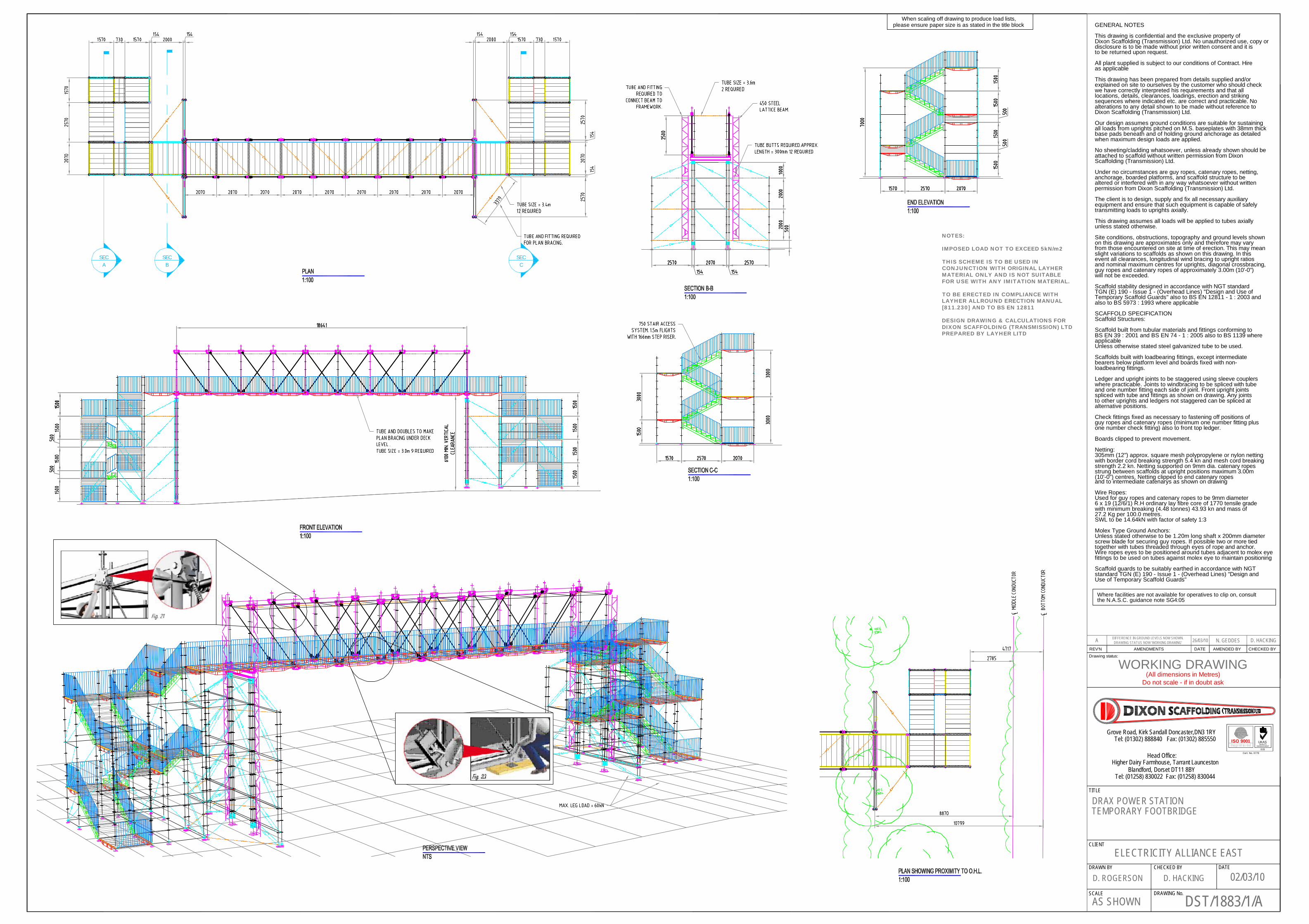
DST/1883/1/AD. ROGERSON D. HACKING 02/03/10
DRAX POWER STATIONTEMPORARY FOOTBRIDGE
AS SHOWN
ELECTRICITY ALLIANCE EAST
A DIFFERENCE IN GROUND LEVELS NOW SHOWN.DRAWING STATUS NOW 'WORKING DRAWING' 26/03/10 N. GEDDES D. HACKING
NOTES:
IMPOSED LOAD NOT TO EXCEED 5kN/m2
THIS SCHEME IS TO BE USED INCONJUNCTION WITH ORIGINAL LAYHERMATERIAL ONLY AND IS NOT SUITABLEFOR USE WITH ANY IMITATION MATERIAL.
TO BE ERECTED IN COMPLIANCE WITHLAYHER ALLROUND ERECTION MANUAL[811.230] AND TO BS EN 12811
DESIGN DRAWING & CALCULATIONS FORDIXON SCAFFOLDING (TRANSMISSION) LTDPREPARED BY LAYHER LITD