The development and calibration of South Africa’s … Hub Items/Attachments/11697/Industr… · A...
48
The development and calibration of South Africa’s National Standards for Water Retaining Structures Interim Report by JA WIUM Department of Civil Engineering University of Stellenbosch December 2007 WRC Project Number K5/1764
Transcript of The development and calibration of South Africa’s … Hub Items/Attachments/11697/Industr… · A...
The development and calibration of South Africa’s National
Standards for Water Retaining Structures
Interim Report
by
JA WIUM
Department of Civil Engineering
University of Stellenbosch
December 2007
WRC Project Number K5/1764

WRC Project Number K5/1764
1
TABLE OF CONTENTS
1. Background ......................................................................................................................... 3
2. Purpose of this document................................................................................................. 3
3. Methodology ....................................................................................................................... 4
4. Current Progress ............................................................................................................... 5
4.1 Introduction ......................................................................................................................... 5
4.2 Industry survey on current design practice : ................................................................. 6
4.2.1 Type of structures .............................................................................................................. 6
4.2.2 Design practice .................................................................................................................. 6
4.2.3 Construction practice ........................................................................................................ 7
4.2.4 Materials .............................................................................................................................. 7
4.2.5 South African conditions ................................................................................................... 8
5. Code evaluation ................................................................................................................. 8
5.1 Introduction ......................................................................................................................... 8
5.2 BS 8110 together with BS 8007 ...................................................................................... 9
5.3 EN 1992-1 together with prEN 1992-3 ........................................................................... 9
5.4 Codes in South-Africa: .................................................................................................... 10
5.5 SABS 0100:1 .................................................................................................................... 11
5.6 Code comparisons........................................................................................................... 11
6. Workshop .......................................................................................................................... 12
6.1 General .............................................................................................................................. 12
6.2 Outcome ............................................................................................................................ 12
6.3 Steering committee ......................................................................................................... 13
7. Assessment and identification of needs ...................................................................... 13
7.1 Current practice : ............................................................................................................. 13
7.2 Design code development and status .......................................................................... 14
7.3 Code comparisons........................................................................................................... 15
7.4 Other needs identified : .................................................................................................. 15
8. Summary and conclusion ............................................................................................... 15
9. References ....................................................................................................................... 16
ANNEXURE A .................................................................................................................................. 17
ANNEXURE B .................................................................................................................................. 21
ANNEXURE C .................................................................................................................................. 29
ANNEXURE D .................................................................................................................................. 43
WRC Project Number K5/1764
2
The development and calibration of South Africa’s National
Standards for Water Retaining Structures
Synopsis
The Water Research Commission appointed the Department of Civil Engineering at the University of
Stellenbosch to develop and calibrate a national standard for the design of concrete water retaining
structures in South Africa. This document reports on the progress and on an evaluation of the original project
plan.
An industry survey was undertaken amongst designers, contractors and owners to determine the status of
the current industry. Information was gathered on design methods, standards applied and parameters used
in the design. The survey also provided information on types of structures, materials and methods of
construction.
The current practice in South Africa is to base the design of water retaining structures on the British
Standard. This standard will soon be replaced by the Eurocode. An assessment was made of the
relationship between current standards, being the concrete design code and the code for water retaining
structures. A comparison was also made between the design methods for crack width as performed using
British Standards and the Eurocode.
A one day workshop was held in Stellenbosch where designers, contractors and owners of water facilities
presented the scope and extent of design, construction and maintenance of water retaining structures in
three regions in South Africa. The three regions are Gauteng, KwaZulu-Natal and the Western Cape.
The information gathered to date, and the investigations performed, confirmed the scope and original plan
for the project. Specific needs were also identified which will either be included in this project or which can
form the basis of additional studies, depending on the nature of the specific need.

WRC Project Number K5/1764
3
The development and calibration of South Africa’s National
Standards for Water Retaining Structures
1. Background
To assist in design, construction, quality control and maintenance of water retaining infrastructure, it is
important to develop applicable South African National Standards. Extensive research has and is
internationally being focused at deriving rational design rules for Civil Engineering Infrastructure and
buildings and may be exploited for local application. However, careful translation to local conditions,
construction materials and technologies is imperative.
Considering the fact that no South African standard exists for the design of concrete water retraining
structures, a natural step is to develop such a standard for local application. Most frequently, reference is
made to the British Standard BS8007 for this purpose. However, consideration of local conditions, practice
and materials is essential, calling for an in-depth study to ascertain appropriateness of design rules and
guidelines, as well as harmonization of related codes. To achieve such rational and appropriate procedures
and guidelines for the South African Industry, it is necessary that a South African National Standard for
Water Retaining Structures is developed. In addition, the related standards for loading actions (SANS10160)
and relevant construction materials (SANS10100) are to be revised to include appropriate provisions for
water retaining structures.
The Department of Civil Engineering at the University of Stellenbosch was appointed to develop a draft
design code for concrete water retaining structures in South Africa.
The creation of a code of practice for water retaining structures will form part of a basis from which the
quality, durability and maintenance of water retaining infrastructure can be managed in South Africa.
Although not an innovative creation on its own, it will provide local authorities and water authorities a basis
from which systems can be set up in a co-ordinated manner for the management of durable infrastructure.
The establishment of a code of practice for water retaining structures will thus provide one of the building
blocks which is necessary to develop innovative water infrastructure management systems.
2. Purpose of this document
The purpose of this document is to :
- report on the progress of the project with the aim to
- provide an assessment of the original project plan.

WRC Project Number K5/1764
4
First, the original anticipated methodology of the project is summarized. A more comprehensive description
of the project plan is presented in ANNEXURE A.
The current progress is then presented with a report on actions performed and needs identified. The initial
actions consisted of information gathered through an industry survey and feedback received during a one
day workshop.
Furthermore, evaluations were carried out to access the status and relationship between current codes, and
to make initial comparisons. This document reports on the current status of this evaluation.
Finally, the report presents the way forward and needs which have been identified to date.
The document is finally completed with a summary and a conclusion.
3. Methodology
A comprehensive proposal for an enforceable standard for the design of concrete water retaining structures
is the ultimate goal in this project. The project will focus on making significant steps towards this ultimate
output by developing a design manual for water retaining structures, also referred to as the Design Guide or
Draft Code in this document.
The methodology is described in the original project plan which is presented in ANNEXURE A. The
methodology is briefly summarized in the following paragraphs.
Phase I : Study of existing codes and a comparison thereof :
- Topic 1 : Assessment of Eurocode provisions (EN 1992-3 and EN 1992-1)
- Topic 2 : Assessment of BS 8007 and BS 8110 and comparison of British codes with
Eurocode
Phase II : A Workshop involving participants from industry, academic institutions and owners
- The outcome should be a frame work from which the code can be developed
- Topic 3 : Investigation into local climatic conditions, materials, including aggregates and
concrete practice, reliability standards and general design and construction practice in the
optimization of specifications for a design standard for water retaining structures.
- Topic 4. Identification of activities for the development of a standard will be performed,
including the formulation of a review by committee and ultimately other stakeholders.
Furthermore, identification will be performed of supporting investigations in the process of
calibration and optimization to provide the basis for the standard.
WRC Project Number K5/1764
5
Phase III : Theoretical investigations as identified under Topic 4 of Phase II. These will be necessary for the
compilation of design guidelines which will form the basis of the proposed design code. The
research project in this phase will consist of the process of calibration and optimization in
support of the design guidelines.
Phase IV : Compilation of design guidelines, based on the results of the research in Phase III. The design
guidelines will be in the format of a Draft Code, which will at the completion of this project, be
coordinated by the Code Committee to become the new Code. The guidelines will also address
the requirements for the reinforced concrete design of low cost underground water storage
facilities using harvested rainwater which is stored in reservoirs for irrigation and livestock.
Phase V : A seminar will be held in Stellenbosch during which designers, local authorities and other stake
holders will be trained in the provisions and application of the design guidelines.
4. Current Progress
4.1 Introduction
In order to assess local conditions, the status of current practice, and to obtain information from
stakeholders, an industry survey was undertaken as part of a 4th year undergraduate research project.
The following actions were undertaken by this study :
- An industry survey on current design practice
- An industry survey on current construction practice and materials
An assessment was also performed of existing codes. The assessment consisted of an evaluation of the
relationship between different codes, and comparisons performed on clauses used for calculating crack
width. Crack width calculation is one of the important parameters in the design of concrete water retaining
structures.
Furthermore, a workshop was held with designers, contractors and clients (owners) to identify needs from
the industry, to obtain buy-in and to get feedback on the proposed project.
Through these three actions (industry survey, code comparison and workshop) the current needs and status
were identified. Furthermore, the proposal for the establishment of a design code for water retaining
structures was brought to the attention of people in practice.
The following three components of the study are therefore presented under separate headings in the
following paragraphs:
WRC Project Number K5/1764
6
- Industry survey
- Code evaluation
- Workshop
4.2 Industry survey on current design practice :
The information for the industry survey was partly obtained through a final year under graduate (4th year)
research project carried out as partial requirements for the degree of Bachelor of Science in Civil
Engineering (Le Roux, 2007).
Interviews were conducted with designers, contractors and owners of water retaining structures located in
Gauteng, Cape Town and Durban. The names of people who provided information are listed in ANNEXURE
B.
The following paragraphs provide an extract from the information obtained through the industry survey. More
comprehensive information can be found in Le Roux (2007) :
4.2.1 Type of structures
The types of structures considered by persons who participated in the survey include :
- reservoirs (and storage tanks)
o rectangular,
o circular,
o reinforced concrete
o pre-stressed concrete
o flat roofs or dome roofs
- swimming pools
- elevated tanks
- structures for water purification works
4.2.2 Design practice
Analyses of structures are often either performed by hand or by use of available software packages.
Software packages include Prokon, Strap, Strand7 and others. For the design of concrete water retaining
structures, it was confirmed that designers in South Africa to a large extent make use of the British Code for
the design of Water Retaining Structures (BS 8007) to calculate crack widths, determine minimum
reinforcement content, and to obtain details on typical joints.
WRC Project Number K5/1764
7
The above Code however needs to be used in conjunction with a concrete design code, for which BS 8110
(1997) or SANS 10100 (2000) are often used. It was noted that in most cases the serviceability requirements
(crack widths) determine the design of the structure and not ultimate limit state requirements.
Designers in South Africa are not all aware of the fact that the British Code would soon be replaced by the
Eurocodes (EN 1992-1 and EN 1992-3).
It was noted that most often designers use design parameters for temperatures, restraint factors and
material parameters which they have accumulated from experience, or from more experienced designers in
their companies. There is a general lack of generally available information on South African conditions for
these parameters (such as temperatures and material characteristics). Although the information does exist, it
is not necessarily documented to be accessible to all designers. A very similar situation exists for certain
construction details which designers specify on their drawings. Although joint details may have originated
from the British Code, there may be slight variances for local preferences. This information is accumulated
by designers through experience.
It was therefore identified that a need exists for information on design parameters to be used in South Africa.
This includes information on materials, construction details, parameters used in the design such as
temperatures (hydration temperatures for different concrete mixes, formwork types, and climatic regions) and
construction practice.
4.2.3 Construction practice
The construction of water retaining structures is mostly performed by contractors in South Africa with
previous experience in the field. The importance of good construction quality control was emphasized.
Specific items which were highlighted are concrete cover and curing methods.
An extract from the information obtained through the survey is enclosed in ANNEXURE B of this report. This
includes information on wall and roof construction, joints and workmanship.
4.2.4 Materials
The industry survey included sourcing of information on current construction materials. Information was
obtained on the following materials :
- cement
- aggregate
- extenders
- reinforcement
- jointing material
WRC Project Number K5/1764
8
The information in the survey is presented in the under graduate research project report of which an extract
is enclosed in ANNEXURE B. the survey served to identify the current practice and draws the attention to the
variety of materials and regions that need to be addressed for the South African context.
4.2.5 South African conditions
In South-Africa and especially the Western Cape, problems can occur due to very pure water (soft water)
found in mountain streams or rain water. This water is “calcium hungry” and leaches calcium hydroxide
[Ca(OH2)] and [C-S-H]-ions from the hardened cement paste. This situation leads to the degradation of the
cement paste and ultimately the exposure of the steel reinforcement.
This problem can be overcome by the implementation of a lime stabilization plant upstream of the reservoir.
These lime stabilization plants are also known as lime stone reactors. It usually consists of a cylindrical
concrete structure filled with big pieces of lime rock. Water is percolated over the rocks inside the reactor and
some of the lime dissolves into the water. Every few months these reactors need to be inspected and the
lime needs to be replenished.
Most consulting engineers in the Western Cape specify that the mountain water needs to be tested to
identify possible problems regarding soft water.
Another problem with pure water is the lack of impurities. Normally these impurities accumulate inside the
fine cracks which develop due to thermal cracking. These impurities will then, after a few days, seal these
initial cracks and create a watertight structure. The lack of these impurities will however lead to the excessive
leakage of the structure.
It is important that this information be shared with all designers and persons who draw up specifications.
5. Code evaluation
5.1 Introduction
The current code used by designers for the design of reinforced and pre-stressed concrete structures in
South Africa is SANS 10100-1 (2000). This code was developed from and based on the British Code BS
8110 (1997). For this reason, quite a number of engineer in South Africa still make use of BS 8110 for their
designs.
For the design of water retaining structures, South African engineers in general use the British Code BS
8007. This code cannot be used on its own and needs to be used in conjunction with BS 8110.

WRC Project Number K5/1764
9
As a result of developments in Europe, the British Codes will soon be phased out and be replaced by the
Eurocodes. Design of concrete building structures will specifically be performed according to EN 1992-1, and
water retaining structures according to EN 1992-3. The relationship between EN 1992-1 and EN 1992-3 is
similar to the relationship between BS 8110 and BS 8007, in the sense that the design of water retaining
structures needs the general elemental design parts of BS 8110 for the design of structures.
The approach followed by the Eurocodes is that the basic standard will be applicable to all member states,
but individual countries will be able to issue a National Annex with nationally determined parameters for
specific items. In this manner, each country’s design code will consist of a basic Eurocode formulation,
together with a National Annex.
Recent international developments of codes have resulted in the South African structural engineering
fraternity to recognize that an approach needs to be formulated for the next generation of structural design
codes for South Africa. There is a general realization that due to available funding and resources, it would
not be feasible to develop and maintain local codes if these are to be solely South African codes. A seminar
is being planned (February 2008) for stakeholders to discuss the direction which South Africa should take for
its next generation of structural design codes. One of the options which will be debated is the extent to which
new South African codes should adopt or adapt other existing codes such as the Eurocodes.
In this respect, the project leader for this project, Prof J A Wium, has been elected as the chair person for a
committee which will consider the revision of the design code for concrete building structures (currently
SANS 10100- 1 : Part 1 Design).
In the following paragraphs an overview is presented of the relationship between different design codes, their
use in South Africa and in the United Kingdom.
5.2 BS 8110 together with BS 8007
From the survey amongst practicing designers it was established that designers are of the opinion that BS
8007:1987 is still relevant and works for South-African conditions. Most of the engineers feel that the use of
BS EN 1992-3 for the design water retaining structures, which is not currently used locally, will become more
attractive once this code is phased into use in European countries.
None of the engineers that were interviewed acknowledged that they currently use EN 1992-3 for the design
of water retaining structures. This was expected.
5.3 EN 1992-1 together with EN 1992-3
In general EN 1992-3, used in conjunction with the European National Annexes, is not entirely different from
BS 8110 in terms of the design approach. It gives similar answers for those items which have been
evaluated (bending, shear, crack width) and offers scope for more economic structures.

WRC Project Number K5/1764
10
Overall EN 1992-3 is less prescriptive and its scope is more extensive than BS 8110. For example, it permits
the use of higher concrete strengths. In this sense the new code will permit designs not currently permitted
when using BS 8110, and thus give designers the opportunity to derive benefit from the considerable
advances in concrete technology over recent years. The author believes that, after an initial acclimatization
period, EN 1992-3 will be generally regarded as a suitable code and a step in the right direction. The new
Eurocodes are claimed to be the most technically advanced codes in the world.
In EN 1992-1 concrete strengths are referred to by cylinder strengths, which are typically 10-20% less than
the corresponding cube strengths. The maximum characteristic cylinder strength fck
permitted is 90 MPa,
which corresponds to a characteristic concrete cube strength of 105 MPa. These values are given in Table
3.1 of EN 1992-1:2004.
The design of flexural elements to EN 1992-1 is in practice very similar to that of BS 8110. However EN
1992-1 does not generally give element specific design guidance, but more the general principles to be
applied. This approach should be welcomed, as it is less restrictive and may encourage innovative design
methods. EN 1992-1 also allows for reinforcement strengths of up to 600 MPa. The new set of Eurocodes
are logically set out and arranged to avoid repetition.
The EN 1992-3 design code is more specific with regards to the design crack width specifications and the
classification of the water tightness of the structure (refer to Section 7 of EN 1992-3). The calculation of crack
width is thus more laborious with a large number of parameters to attend to.
5.4 Codes in South-Africa:
In South-Africa the use of Eurocode 2 (EN 1992-1) is currently very limited due to the lack of available
information regarding values which are contained in the European National Annexes. A South African
equivalent of the National Annex has not been prepared. There appears to be a current lack of interest
amongst designers due to the fact that these codes have not yet been fully implemented in Europe. There is
however significant interest from the side of code writers and developers in adopting or adapting Eurocode
formulations for a new generation of South African Codes (see information about the Code Summit in
Section 5.1 above).
The design processes in these codes are complicated by the continuous reference to national annexes and
other design codes which are not freely available in South-Africa. No definite design formulae are provided
for the design of concrete members, the basic principles are given and the designer basically has to derive
his/her own formulae.
The EN 1992-3 code makes no provision for structures at very high or very low temperatures. There is also
no reference to any water-stop or jointing material specifications.
WRC Project Number K5/1764
11
5.5 SABS 0100:1
This design code is the primary concrete design code for South-African and its development was based on
the British concrete design code BS 8110.
The South-African design code for the design of water retaining concrete structures will be used in
conjunction with this code. It would therefore be advantageous to prepare the proposed South-African design
code for water retaining structures according to the format of SABS 0100:1 to enhance readability and
compatibility (also to be dependent on the future format of SANS 10100:1).
5.6 Code comparisons
The code currently used by designers in South Africa for the design of concrete water retaining structures is
BS 8007. This code provides a calculation method and guidance for crack width calculations and is used in
conjunction with BS 8110, the design code for concrete structures.
The Eurocode equivalent for the calculation of crack width and design of concrete structures is EN 1992-3
(liquid retaining structures) and EN 1992-1 (concrete structures).
An initial comparison was made between the crack width calculation methods of BS 8007/BS 8110 and EN
1992-3/EN 1992-1. Only flexural cracking was considered and no tensile cracking due to thermal effects was
taken into account. The purpose of the comparison was to determine the extent to which the two codes
(British vs. European) might differ or provide similar results.
The parameters used for the comparisons are presented in ANNEXURE C. The same ANNEXURE also
provides graphs showing the comparison between the two codes.
The design crack width depends on the specific conditions, the choice of the designer, and specifications in
the codes. The value which is very often used when BS 8007 code is applied, is a maximum crack width of
0.2mm. It can be observed from the comparisons between the two codes, that the two codes compare very
well when a crack width of 0.2mm is targeted. For other crack widths there appears to be slight difference
between the codes. This difference increases as the crack width with moves away from the 0.2mm target.
Further comparisons are required for the crack width calculations by the two codes. Such a comparison
should include thermal cracking due to restrained imposed deformations.
A study was also identified in which the reliability of the crack width calculations should be determined. The
reliability level for each of the two codes will be determined. This investigation will form the subject of a MSc
Eng study by Mrs Christian Mcleod from the University of KwaZulu-Natal.

WRC Project Number K5/1764
12
6. Workshop
6.1 General
Phase II of the project included a workshop which was held in Stellenbosch on 17 October 2007. The
following paragraphs provide an overview of the workshop.
The purpose of the workshop was three-fold :
- to expose designers, contractors and client organizations to the project for the development of a
design code for water retaining structures.
- to obtain input and feedback from the participants in order to involve a wider audience.
- to identify practitioners who would serve as members on working group for the development for the
code (steering committee).
The workshop was arranged to include participants of a variety of organizations and regions. To achieve this
aim, a strategy was followed to invite participants from the following regions and affiliations :
- three regions were decided upon : Western Cape, KwaZulu-Natal and Gauteng
- it was decided to invite representatives of each of the following disciplines from each region :
o designer
o contractor
o client body (owner).
Apart from the above participants, staff and students from the University of Stellenbosch and the University
of KwaZulu-Natal also participated in the workshop. The names, affiliations and topics of presentations of the
participants to the workshop can be seen on the enclosed workshop program which is presented in
ANNEXURE D.
ANNEXURE D also includes a summary of the most important information presented by participants at the
workshop.
6.2 Outcome
Following the presentations at the workshop, a discussion was held on the topic of a design code for water
retaining structures in South Africa. The following are some salient points which were raised during the
discussion :

WRC Project Number K5/1764
13
- Information on local conditions such as heat of hydration, material characteristics for different types
of cements and mixes, water quality and purity are not generally available. Specialist design firms
have been able to compile some information through experience. This type of information should be
made available to a broader spectrum of designers
- Although not considered to be part of this project, serious consideration should be given to the
development of a design handbook or manual which can be used by designers.
- The use of pre-cast concrete in the construction of especially rural water retaining structures should
be given more consideration. Guidelines should be developed to allow designers and contractors to
use this type of construction. This will require less site work, less reliance on inexperienced site
laborers, and should ensure a better quality product.
- A new code should not aim to be a local developed code, but should be based on international
norms and developments.
6.3 Steering committee
Participants in the workshop are available to become part of a steering committee for the development of a
code for water retaining structures. The participants are keen that a new code should be developed from an
existing code such as EN 1992-1 and EN 1992-3.
7. Assessment and identification of needs
The actions performed to date provided extensive information on current practice, scope of existing codes
and the needs in South Africa for design of water retaining structures.
Although not described in the initial project plan, by commencing the project with an industry survey proved
to be very useful and beneficial. The survey, the code evaluation and the interaction with participants at the
workshop identified the specific needs for the project, but also identified further needs which are beyond the
scope of this project.
With reference to the original project plan, it can be concluded that Phase I and II of the project have been
carried out. These actions confirmed the original project plan and set the stage for the subsequent phases.
The following paragraphs provide a summary of the needs which have been identified through this first two
Phases of the project.
7.1 Current practice :
From the industry survey it was noted that most often designers use design parameters, such as hydration
temperatures, restraint factors and material parameters which they have accumulated from own experience,
WRC Project Number K5/1764
14
or from more experienced designers in their companies. There is a general lack of available information on
South African conditions for these parameters. Although the information does exist and has been
accumulated over the years, it is not necessarily contained in the Codes used by the designers. A very
similar situation exists for certain construction details which designers specify on their drawings. Although
joint details may have originated from the British Code, there may be slight variances for local preferences.
These details have been accumulated by designers through own experience.
It was therefore identified that a need exists for information on design parameters to be used in South Africa.
This includes information on materials, construction details, parameters used in the design such as
temperatures (hydration temperatures for different concrete mixes, formwork types, and climatic regions) and
construction practice. The material information includes quality of water used in construction and the criteria
required to verify water for impurities, hardness, and other relevant parameters.
The gathering of information on local material characteristics will form the subject of a MSc Eng thesis. A
student is current being sought for this project to start in 2008.
7.2 Design code development and status
Recent international developments of codes have resulted in the South African structural engineering
fraternity recognizing that an approach needs to be formulated for the next generation of structural design
codes for South Africa. There is a general realization that due to available funding and resources, it would
not be feasible to develop and maintain local codes. A seminar is being planned (February 2008) for
stakeholders to discuss the direction which South Africa should take for its next generation of structural
design codes.
Through the use of existing codes (BS 8110 and BS 8007) in the code comparisons that have been made for
this project, as well as through the application of new codes (EN 1992-1 and EN 1992-3) it has become clear
that a development of code for water retaining structures is a development which goes hand in hand with the
development of a concrete design code. The process to formulate a strategy for the development of a
concrete design code has already commenced, with a code seminar planned for February 2008.
Furthermore, the project leader for this project been elected as the chair person for a committee which will
consider the revision of the design code for concrete building structures (SANS 10100 Part 1). It has already
been decided that this revision should either be based an adoption or an adaptation of the Eurocode (EN
1992-1).
The development of the code for water retaining structures can not and will therefore not proceed in isolation

WRC Project Number K5/1764
15
7.3 Code comparisons
It was found through initial comparisons between the British Code (BS 8007) and the Eurocode (EN 1991-3)
that the two codes compare very well when the standard design crack width is targeted. For other crack
widths there appears to be slight difference between the codes.
Further comparisons are required for the crack width calculations by the two codes. Such a comparison
should include thermal cracking due to restrained imposed deformations.
A study was also identified in which the reliability of the crack width calculations will be determined. This
investigation will form the subject of a MSc Eng study by Mrs Christian Mcleod.
7.4 Other needs identified :
Although not considered to be part of this project, other items have been identified which needs specific
attention. These needs can be addressed as a continuation of the current project, or can also run in parallel.
These items are briefly listed below :
- consideration should be given to the development of a design handbook or manual which can be
used by designers.
- the use of pre-cast concrete in the construction of especially rural water retaining structures should
be given more consideration. Guidelines should be developed to allow designers and contractors to
use this type of construction.
8. Summary and conclusion
The purpose of this project is the compilation of a draft code for the design of concrete water retaining
structures in South Africa. An initial project plan included Phase I and II of the project which consists of :
- an evaluation of relevant codes
- a workshop to be held with role players in the industry.
These two phases have now been completed and it has shown that the original project plan is still relevant.
Through an industry survey of design and construction practice, valuable information has been compiled
about conditions and practice in South Africa. This information will now be used as background for the
continuation of the study.
The industry survey assisted to confirm some aspects of the study, such as :
- a need for a compilation of local knowledge on materials and conditions
- the relevance of the current design codes
- the need for guidance on the design of concrete water retaining structures.
WRC Project Number K5/1764
16
The survey and workshop also served to identify specific needs which are considered to be beyond the
scope of this project :
- the compilation of a design manual (or handbook) which can be used in conjunction with the Code
- the need to develop the use of pre-cast concrete as a construction method for rural water storage
reservoirs
9. References
1. Le Roux, W. South African Practice for the design of water retaining concrete structures. Project
report in partial fulfillment for the degree of bachelor in Civil Engineering at the University of
Stellenbosch, 2007.
2. SANS 10160 General Procedures for Loading in Buildings and Industrial Structures. DRAFT. South
African Institute for Civil Engineers, 2006.
3. SANS 10100-1 : South African standard. The structural use of concrete. Part 1 : Design. The South
African Bureau of Standards. Pretoria. 2000.
4. BS EN 1990 : Eurocode 0. Basis of structural design. BSI. 2002
5. BS EN 1991-4 : Eurocode 1. Actions on structures. Silos and tanks. BSI 2006.
6. BS EN 1992-1 : Eurocode 2. Design of concrete structures. General requirements. BSI. 2004
7. BS EN 1992-3 : Eurocode 2. Design of concrete structures. Liquid retaining and containment
structures. BSI. 2006
8. BS 5337 : The structural use of concrete for retaining aqueous liquids. BSI. 1976
9. BS 8007 : British Standard code of practice for design of concrete structures for retaining aqueous
liquids. BSI. 1987
10. BS 8110 : British Standard. Structural use of concrete. Part 1. Code of practice for design and
construction. BSI. 1997.

WRC Project Number K5/1764
17
ANNEXURE A
ORIGINAL PROJECT PLAN
A Methodology
A comprehensive proposal for an enforceable standard for the design of concrete water retaining structures
is the ultimate goal in this project. The project will focus on making significant steps towards this ultimate
output by developing a design manual for water retaining structures, also referred to as the Design Guide or
Draft Code in this document.
The methodology described below was originally identified for the project. This methodology is briefly
presented in the following paragraphs. This presentation is then followed by a description of the work
performed to date, followed by a proposal for the way forward.
A.1 Phase I :
Phase I of the project was defined as follows :
The relationship between BS8007, BS5337, BS8110 and SANS 10100:2003 needs to be studied in the light
of the future replacement of British structural design standards by the Eurocodes. Applicable Eurocodes
include BS-EN 1992 Structural concrete design, in particular BS-EN 1992-1 Design of Concrete Structures.
General requirements and BS-EN 1992-3 Liquid retaining and containment structures.
The development of a code of practice for water retaining structures is thus a process by which existing
knowledge and experience will be considered, assessed, and applied to the conditions in South Africa and to
the benefit of its people. Whereas the usual work method involves human resource training in the form of
full-time post graduate students who are guided by the academic team members to perform the research,
the first phase will involve the research specialists directly to a large extent.
The research for this phase of the project consists of desk top studies and literature reviews.
The following subjects are being addressed :
- Topic 1. Assessment of Eurocode provisions for the design of water retaining structures from
BS-EN 1992-3 Liquid retaining and containment structures, its related general concrete
standard BS-EN 1992-1 General rules and rules for buildings, the related standards on
actions BS-EN 1991-4 Actions in silos and tanks and the related aspects from BS-EN 1990
Basis of the design of structures.
- Topic 2. The present use of BS 8007 for water retaining structures in South Africa is
facilitated by the fact that the local standard for concrete structures SANS 10100 is

WRC Project Number K5/1764
18
referenced to BS 8110. The implications of changes in British practice are to be assessed in
order to provide guidance on implications for South African practice.
A.2 Phase II :
Phase II of the project was envisaged as follows :
To establish the support base, but also ensure the relevance of the research activity and to obtain buy-in by
all stake holders, a workshop will be held in Stellenbosch as part of Phase II of the project. Keynote
contributions will be solicited from national participants and potentially one international specialist.
Representatives from local authorities, consulting engineering firms, academic institutions, and construction
companies will be invited. It is envisaged that the workshop will entail one day, of which the morning session
will be devoted to formal presentations and the afternoon for round table discussions.
The outcome of the workshop will be a comprehensive framework for the development of the Code, as well
as the selection of a steering committee to which the research project can report. The steering committee will
also act as the SAICE committee responsible for the development of the revised Code for Water Retaining
Structures.
Specific research subjects that will follow upon the workshop are :
- Topic 3. Investigate the implications of local climatic conditions, materials, including
aggregates and concrete practice, reliability standards and general design and construction
practice in the optimization of specifications for a design standard for water retaining
structures.
- Topic 4. Identification of activities for the development of a standard will be performed,
including the formulation of a review by committee and ultimately other stakeholders.
Furthermore, identification will be performed of supporting investigations in the process of
calibration and optimization to provide the basis for the standard.
Where necessary supporting research will be identified, particularly regarding local conditions, materials and
practice. For this purpose, specific attention will be paid to identify the conditions on which existing codes
are based, as well as the conditions for which the new provisions will be developed. Together with
information gained from Topic 3 above, this information will be used in the motivation for the development of
new code provisions.
The efficiency of this process will be largely improved by reference to BS-EN 1992-3 and associated
standards.
WRC Project Number K5/1764
19
The research on Topics 3 and 4 will consist of desk top studies and will be performed by post graduate
students in Stellenbosch and at the University of KwaZulu-Natal.
A.3 Phase III :
Phase III was defined as follows :
This Phase will consist of the theoretical investigations as identified under Topic 4 of Phase II. These will be
necessary for the compilation of design guidelines which will form the basis of the proposed design code.
The research project in this phase will consist of the process of calibration and optimization in support of the
design guidelines.
A wealth of existing information is available on the effect of different materials which determine concrete
characteristics such as creep, shrinkage and moduli of elasticity . The effect of aggregate is of particular
importance. This information will be evaluated for its incorporation into the code. It is not envisaged that
further material testing will be performed to add to this database of information. Where information is lacking
for the design guidelines, current information will be used as a fall back option.
However, sample tests will be performed on structural elements (beams or slabs) to confirm the calculation
methods adopted. Material tests will be performed to determine the characteristics of materials for these
tests.
For the execution of these projects postgraduate students will be drafted and the research will be performed
by post graduate students in Stellenbosch and at the University of KwaZulu-Natal.
A.4 Phase IV
The actions for Phase IV of the project were envisaged as follows :
This phase will consist of the compilation of design guidelines, based on the results of the research in Phase
III. The design guidelines will be in the format of a Draft Code, which will at the completion of this project, be
coordinated by the Code Committee to become the new Code. The final completion of a Design Code is not
included in this proposal. The reason being that the administrative process of formatting, printing and the
public commentary process can be rather lengthy, a process normally managed by the code committee. The
project does however include the preparation of the Draft Code which includes all the necessary technical
information as required for the Code.
The guidelines will also address the requirements for the reinforced concrete design of low cost underground
water storage facilities using harvested rainwater which is stored in reservoirs for irrigation and livestock.
WRC Project Number K5/1764
20
The work will be performed partly by a postgraduate student but also by an undergraduate student or young
engineer. The work will be performed in Stellenbosch.
A.5 Phase V
Phase V of the project was planned as described below :
Upon completion of the design guidelines (Draft code), a seminar will be held in Stellenbosch during which
designers, local authorities and other stake holders will be trained in the provisions and application of the
design guidelines. During this seminar, the dissemination of the compiled information will be transferred to
the practitioners by presentation of the guidelines as well as by suitable examples which will serve the
purpose of a design aid.. Local authority representatives will be schooled in the application of the document
which will enable them to oversee the provision of durable, economic infrastructure to the benefit of the
community.
WRC Project Number K5/1764
21
ANNEXURE B
INDUSTRY SURVEY
Sources of information for industry survey:
The following people were interviewed and presented information to be used in this project (Le Roux, 2007):
Mr. H van Dalsen. Africon - Pretoria. July 2007. Designer.
Mr. K Bokelman. Africon - Cape Town. September 2007. Designer.
Mr. G Mosterd. Bergstan - Cape Town. September 2007. Designer.
Mr. H Niehaus. Ninham Shand - Cape Town. September 2007. Designer.
Mr. W Jerling. Stefanutti & Bressan Civils - Johannesburg. Workshop, 17 October 2007.
Contractor.
Mr. S Scruton - City of Durban. Workshop, 17 October 2007. Client.
Mr. A Singels - City of Cape Town. Workshop, 17 October 2007. Client.
B.1 CONSTRUCTION PRACTICE AND MATERIALS
The information presented in this ANNEXURE is an extract from project report of the 4th year undergraduate
research project by W le Roux (2007). More comprehensive information can be found in the project report.
B.1.1 Construction
Various different construction methods exist and this chapter provides a brief overview of some of the
methods used to construct water retaining structures.
The following aspects will be discussed in this chapter:
Walls
Roofs
Foundations and floor slabs
Joints
Workmanship
B.1.1.1 Wall construction
Some designers specify that no vertical construction joints may be used when walls are cast for circular
reservoirs (Figure 4.1). This means that walls shall be cast in lifts of a height that permits each lift to be
poured without interruption in one continuous operation. A single circular section is cast monolithically,
then the shuttering is raised and another ring is cast. This process is repeated until the reservoir is
completed. Normally about four or five lifts is specified depending on the size of the reservoir and the
according amount of concrete in a single pour.

WRC Project Number K5/1764
22
Other designers favor a different method of wall casting which allows vertical construction joints. The
most popular method will be to cast quarter panels with two lifts, thus eight individual casts will be made.
B.1.1.2 Roof construction
Two main types of roofs are normally constructed:
a. Flat slab
A flat slab roof without beams or drops is the most convenient form of roof to construct and is the
easiest to maintain and clean.
b. Dome
These types of roofs can be found on some of the older municipal reservoirs. These roofs are built
by specialist contractors with the necessary experience and equipment.
Modern reservoirs are rarely built with these types of roofs due to:
The difficulty and complexity of the construction process.
These roofs are not aesthetically pleasing.
It is difficult to seal the interface between the roof and the wall.
These types of roof are approximately 10 percent more expensive than flat slab roofs.
B.1.1.3 Foundations and floor slabs
Floor slabs are usually constructed as reinforced single panel slabs. These single slabs are normally
cast in a rectangular shape for rectangular reservoirs or in a radial pattern for circular reservoirs. The
construction joints are normally specified on the layout drawing together with the arrangement in which
the individual panels should be cast.
Often engineers specify that floor slabs may be cast without construction joints. This method however
requires a substantial increase in the amount of steel to prevent cracking due to plastic and drying
shrinkage and thermal movement. The method of casting alternate strips is not encouraged by
designers.
B.1.1.4 Joints
Horizontal construction joints are permitted in the reservoir wall in positions indicated on the drawings or
as approved by the Engineer. No vertical joints are however permitted unless specified by the Engineer
under special circumstances, such as water conditions that is conducive to autogenous healing.
a. Causes of joint failure
The main causes of joint failures include :
Poor workmanship and detailing which includes:

WRC Project Number K5/1764
23
Incorrect positioning of joints.
Incorrect positioning of water stops.
Incorrect positioning of the joint fillers.
Poor preparation of concrete between pours.
Joints opening beyond the normal operating range of the sealants.
Failure of jointing materials including:
Deterioration of joint fillers or sealers – through age embrittlement or shrinkage.
Splitting of water stops – due to embrittlement or over extension.
b. Effects of joint failures
When joint failures occur the following effects can be seen on the structure :
Leakage inwards or outwards from the reservoir.
Cracking of the construction materials.
B.1.2 Workmanship
Poor workmanship at the time of construction can result in a number of defects. In concrete construction
the two most common deficiencies, which result in porous concrete, are air pockets and honeycombing.
Air pockets or entrapped air are usually the result of insufficient compaction (vibration). Honeycombing
occurs when the cement paste does not completely fill the spaces between the coarse aggregate
particles. It may be caused by either incomplete compaction or by grout loss at joints in the formwork.
Other defects that may occur as a result of poor working practices include:
Poor preparation of kickers.
Cold joints forming leakage paths.
Misplaced or moved water stops.
Loss of section due to failure of previous repairs.
Poor grouting of shutter tie holes (walls), pipes and ducts.
One of the most important factors which affects the quality and performance of the final concrete is
curing. It is essential that curing starts relatively soon after the initial set of the concrete to achieve a
durable and impermeable concrete. Some of the curing methods favored by engineers include
:
A constant fog spray applied to the concrete surface.
Members covered in wet hessian and wrapped in plastic sheeting.
Membranes painted onto the concrete surface to retain internal concrete moisture.

WRC Project Number K5/1764
24
B.1.3 Types of materials
This chapter reports on the various types of materials which are used in the construction process as well as
the properties of these materials. This information is based on the interviews that were held with the
designers and also information obtained from literature.
The following materials will be discussed in this section:
Cement
Aggregate
Extenders
Reinforcement
Jointing materials
B.1.3.1 Cement properties and content
The minimum cement content of a concrete mix should be 325 kg/m3. This content should however not
exceed 400 kg/m3 for ordinary Portland cement (opc) or cement containing ground granulated
blastfurnace slag (GGBS) or 450 kg/m3 where cements containing pulverized fuel ash/fly ash (PFA/FA)
is used. A maximum water/cement ratio of 0.55 is used for normal Portland cement. When PFA or GGBS
is included into the mix this ratio should be reduced to 0.50.
Typical cement choices for water retaining structures include:
50/50 portland cement/GGBS
70/30 portland cement/FA
B.1.3.2 Aggregate properties
Normally coarse aggregates with a low coefficient of thermal expansion are preferred. The proportions of
the various aggregates shall be such as to produce a well designed concrete mix with a density of at
least 2400 kg/m3 and minimum 28 day strength of 35 MPa. The following types of aggregate are
frequently used in South-Africa:
Dolomitic aggregates
This type of aggregate is normally specified in the construction of sewage treatment works.
Dolomitic aggregates are however not widely available throughout South-Africa. In the Western
Cape it is difficult to procure this type of aggregate.
Hornfels
This type of aggregate is mostly used in the Western Cape where Dolomite aggregates are
scarce. The problem with Hornfels is the reaction between the aggregate and the cement,
known as the alkaline-silicate reaction (ASR). This reaction occurs when the silica in the
aggregates become susceptible to attack by alkalis (Na2O and K2O) originating from the cement
or other sources. During this reaction an alkali-silica gel is formed which can absorb water and
swell, generating internal stresses resulting in cracking and disruption of the aggregate and

WRC Project Number K5/1764
25
cement paste. In some cases pop-outs are formed where an isolated reactive particle occurs
close to the surface of the concrete.
The following precautions may be taken to prevent ASR:
o Limit the alkali content of the concrete mix.
o Use replacement materials like GGBS or PFA
B.1.3.3 Extenders
It is of cardinal importance to specify the amount and type of extender which should be included in the
mix. If the percentage of extender is not specified then most of the contractors assume that the mix
should contain a 50:50 ratio of opc:extender.
B.1.3.4 Fly Ash or Pulverized Fuel Ash
Fly Ash provides various benefits when used in conjunction with ordinary Portland cement. These
advantages include:
Increased abrasion resistance
Enhanced durability
A reduction in the reaction between silica aggregates and alkalis in the cement (ASR).
Fly Ash is however not widely available. Fly Ash is not available in the Western Cape or KwaZulu-Natal.
In these regions designers opt for the use of ground granulated blastfurnace slag as an extender to the
concrete mix. The maximum allowable proportion of Fly Ash in the concrete mix should not exceed 35
percent.
B.1.3.5 Ground Granulated Blastfurnace Slag
GGBS increases the density of the concrete and results in a more durable concrete. In the Western
Cape designers specify Corex slag which originates from the Corex steel works at Saldanha.
The necessary care needs to be taken when implementing slag into the concrete mix. If the correct
curing is applied then the slag will result in an excellent concrete mix. If insufficient curing is however
allowed, a great amount of plastic shrinkage will occur which will lead to the development of plastic
cracks.
The amount of slag included in the mix can be increased to as much as 50 percent of the total mix.
Increased amounts of slag lead to the reduction of panel sizes which can be cast at once. This is due to
the increased plastic shrinkage. In normal water retaining structures the amount is limited to a maximum
of 20 percent.
WRC Project Number K5/1764
26
B.1.3.6 Reinforcement properties
Normally high-strength steel with a ribbed or a deformed surface and a yield or proof stress of 460 MPa
will be prescribed as reinforcing steel. BS 8007 prescribes a material partial safety factor of γm=1.15 for
reinforcing steel.
Fixing of reinforcing bars on site by welding and heating is not permitted since the tensile strength of the
reinforcing bars is influenced when they are heated above a certain temperature.
When prestressing steel is used all cutting thereof shall be performed with a high speed abrasive cutting
wheel or by a method approved by the engineer. Flame cutting will not be permitted under any
circumstances.
Under certain circumstances where highly corrosive materials are contained special measures can be
taken to improve the durability and corrosion resistance of the reinforcement. Normal reinforcing bars
may be hot-dip zinc galvanized, epoxy-coated or even replaced by stainless steel reinforcement. These
measures are however not widely used in South-Africa due to the increased cost thereof. The availability
of stainless steel reinforcing bars also varies considerably throughout South-Africa. These measures
would typically be applied at splash walls exposed to seawater, sewage treatment works or in places
where highly corrosive water is a problem like in the Middle East. In South-Africa designers favor the
method of increased concrete cover rather than altering the reinforcement type.
The following paragraph will discuss the method of protection and the effectiveness of galvanized
reinforcement.
The zinc coating provided by galvanizing is more anodic than the steel reinforcing bars and so will
corrode preferentially, thus protecting the steel. Zinc is however susceptible to rapid attack where high
levels of residual chlorine are present. The additional short period of protection provided by the zinc
coating may not justify the increased cost of galvanizing.
a. Causes of steel reinforcement corrosion
The corrosion of reinforcement is normally caused due to:
Chemical attack, resulting in loss of alkalinity of the concrete from:
Carbonation
Acid attack
Carbonate imbalances
Chloride attack
Cracking
Exposure of prestressing bands to water leaking outward or groundwater.
WRC Project Number K5/1764
27
b. Effects of reinforcement corrosion
The corrosion of steel reinforcement leads to:
The loss of structural integrity due to the loss of a steel section.
The loss of bond and the reduction in concrete cross-section as a result of spalling.
Cracking of the concrete due to the expansive corrosion products.
B.1.3.7 Jointing materials
Jointing materials may be classified as:
a. Joint fillers
They consist of compressible sheets or strips of material fixed to the face of the first-placed concrete
and against which the second-placed concrete is cast.
They provide the initial separation between the faces of the concrete and compress under the
predetermined expansion from each face of the concrete.
Only non-rotting and non-absorbent materials, polyethylene, should be used as joint fillers.
b. Waterstops
Waterstops are preformed strips of durable, impermeable material that are wholly or partially
embedded in the concrete during construction.
They are located across joints in the structure to provide a permanent liquid-tight seal during the
whole range of joint movements.
Waterstops are normally made from durable Poly-Vinyl Chloride (PVC), stainless steel, copper or
rubber compounds.
The problem with PVC waterstops is that they are difficult to bend and hold in place inside the
formwork. Stainless steel is not widely available throughout South-Africa and copper is relatively
expensive.
c. Joint sealing compounds
These materials (or sealants) are impermeable, ductile materials that are required to provide a liquid-
tight seal by adhesion to the concrete throughout the range of joint movements.
The sealing performance is obtained by permanent adhesion of the sealing compound to the
concrete each side of the joint only and most sealants should be applied in conditions of complete
dryness and cleanliness.

WRC Project Number K5/1764
28
The long-term performance of a joint sealing compound depends on its formulation, the
workmanship with which it is prepared and applied as well as the circumstances of the structure.
Joint sealing compounds are normally made up of thermoplastics like bitumen rubber or else
chemically curing elastomeric compounds like elastomeric polyurethane is used.

WRC Project Number K5/1764
29
ANNEXURE C
COMPARISONS BETWEEN CODES
C.1 DESIGN PARAMETERS AND ASSUMPTIONS
This chapter provides the information on design parameters and assumption which were used in the
calculations for the comparison of BS 8007 and EN 1992-3.
The following design parameters have been used in the crack calculations which follow in the follow section :
C.1.1 Material density
Density of earth = 18 kN/m3
Density of concrete = 24 kN/m3
Density of water = 9.81 kN/m3
C.1.2 Material strengths
Compressive cube strength of concrete (fcu) = 30 - 35 MPa when using BS 8007:1987.
Compressive cylinder strength of concrete (fck) = 28.57 MPa when using prEN 1992-3.
Corresponds to cube strengths of 35 MPa. (refer to Table 3.1, EN 1992-1-1).
Yield strength of reinforcement (fy) = 450 - 460 MPa.
Modulus of elasticity of steel (Es) = 200 GPa.
C.1.3 Thermal parameters
Coefficient of thermal expansion (α) = 10 x 10-6
K-1
. (refer to prEN 1992-3, page 8)
T1 = 15˚C (refer to BS 8007:1987, Table A.2).
T2 = 15 - 20˚C (Designers in Cape Town and Pretoria normally specify these values, depending
on the season).
C.1.4 Design crack widths
Design crack width = 0.2 mm when using BS 8007:1987.
Design crack width = 0.2 - 0.05 mm when using prEN 1992-3 (refer to prEN 1992-3, page 11).
Concrete cover = 40 mm for normal non-aggressive potable water (see BS 8007:1987, page 6).
C.1.5 Load factors and conversion factors (see Tables 9.1 and 9.2)
Partial load factor for water γL= 1.4 when using BS 8007:1987.
Partial load factor for water γL= 1.2 when using prEN 1992-3 (refer to EN 1992-1).
Conversion factors: 1 N/mm2 = 1 MPa / 1 kN/mm
2 = 1 GPa.

WRC Project Number K5/1764
30
Design assumptions
The following assumptions were made for the crack width calculations :
Only consider cracking due to bending.
Consider a wall section of unit width (b = 1 m).
Consider a wall of thickness h ≤ 1 m.
Effective depth of concrete (d) = 330 mm (or else d = h - d’).
No pre-or-post tensioned tendons will be used, only reinforcing bars.
Cracking will be determined due to long-term loading.
Calculation of creep factor according to SABS 0100:1, Figure C.1, page 191.
Calculation of effective modulus of elasticity of concrete:
When using BS 8007:1987 refer to SABS 0100-1, page 177.
When using prEN 1992-3 refer to EN 1992-1-1, page 130.
Use only high bond ribbed bars.
No moment redistribution is allowed.
Reinforcement only consists of one diameter bar and not a mixture of bars.
TableC.1 Partial safety factors
SABS 0100:1 ULS 1.2 Dn + 1.6 Ln
SLS 1.1 Dn + 1.0 Ln
BS 8110 ULS 1.4 Dn + 1.6 Ln
SLS 1.0 Dn + 1.0 Ln
EC 2 ULS 1.35 Dn + 1.5 Ln
SLS 1.0 Dn + 1.0 Ln
Table C.2 Material partial safety factors
BS 8110 Concrete γm=1.5
Reinforcing γm=1.15
EC 2 Concrete γm=1.5 (subject to national annex)
Reinforcing γm=1.15 (subject to national annex)

WRC Project Number K5/1764
31
C.2 COMPARISON BETWEEN BS 8007 AND prEN 1992-3 THROUGH CRACK CALCULATIONS
This section presents the comparison of the two design codes through the calculation of crack widths in a
mature concrete section.
Only flexural cracking is considered in this section. No tensile cracking or cracking caused by thermal effects
is taken into consideration.
Both BS 8007:1987 and prEN 1992-3 have their own set of design formulae for the calculation of crack
widths in concrete due to bending.
When using BS 8007:1987 the following simple procedure can be used to determine the surface crack
widths of a concrete section:
1. Calculate the service bending moment (Ms).
2. Calculate the depth of the neutral axis, lever arm and the steel stress by elastic theory.
3. Calculate the surface strain allowing for the stiffening effect of the concrete.
4. Calculate the crack width.
When using prEN 1992-3, a similar procedure is applied for the calculation of crack widths:
1. Calculate service bending moment.
2. Calculate the neutral axis depth of the cracked section.
3. Calculate the stress in the tension steel (σs).
4. Calculate the maximum crack spacing.
5. Calculate the crack width.
Comprehensive Excel spreadsheets were prepared containing the design formulae of both BS 8007:1987
and prEN 1992-3. The data for the graphs that are presented here was compiled from these Excel sheets.
The two design codes are compared to each other by means of graphs. Certain specific parameters were
incremented and the effect on the crack width was tabulated. These tabulated values were then plotted to
visualize the trend of the design formulae. In the top right hand corner of each graph the parameters are
listed which were used during the analysis
As a verification (of the calculations and the software!) a commercial software package (PROKON) was used
to calculate crack widths. The Concrete Crack module in this software has the functionality of changing
between design codes. The user can specify which design code he/she wants to use for the crack
calculation. Both sets of design codes in the software (PROKON) were compared to each other as well as to
the spreadsheet calculations described above.
The following four data sets are presented in each of the seven figures listed below:
BS8007 – Data from the spreadsheets when using BS 8007:1987.

WRC Project Number K5/1764
32
EC 2 – Data from the spreadsheets when using prEN 1992-3.
Prokon_BS – Data from Prokon when using BS 8007:1987.
Prokon_EC – Data from Prokon when using prEN 1992-3 (Eurocode 2).
For details regarding the source data refer to Section B1 above.
The following seven graphs were compiled to compare the design formulae:
Figure C.1 Crack width versus service moment
Figure C.2 Crack width versus reinforcement area
Figure C.3 Crack width versus section thickness
Figure C.4 Crack width versus steel ratio
Figure C.5 Crack width versus moment ratio
Figure C.6 Crack width versus bar spacing
Figure C.7 Crack width versus bar diameter
The figure below will be used to guide the reader through the set of graphs. It will be repeated at the start of
each page and the appropriate block, which corresponds to the specific graph on that page, will be
highlighted. This method will be used to illustrate progression and thus guide the reader through the set of
graphs. A brief discussion of each graph also follows directly after each graph.
Graphs
Variable
Service
Moment
Variable
Reinforcement
Area
Variable
Section
Thickness
Variable Bar
Diameter
Variable Bar
Spacing
Variable
Moment Ratio
Variable Steel
Ratio

WRC Project Number K5/1764
33
C.2.1 Crack width versus service moment
Figure C.1 Crack width versus service moment
Figure C.1 presents an interesting comparison between the design codes and the manner in which the
crack width increases with an increased service moment.
It is clearly shown that the service moment is directly proportional to the predicted crack width which
develops within the concrete.
Graphs
Variable
Service
Moment
Variable
Reinforcement
Area
Variable
Section
Thickness
Variable Bar
Diameter
Variable Bar
Spacing
Variable
Moment Ratio
Variable Steel
Ratio

WRC Project Number K5/1764
34
There is a slight difference between the BS 8007:1987 and the Eurocode 2 spreadsheet-values.
The values obtained when using Prokon with BS 8007:1987 almost exactly match the values when using
the BS 8007-spreadsheet.
When using Eurocode 2 in Prokon, the values differ quite a lot from the spreadsheet values as can be
seen with the bottom line which lies below the other three sets of values.
WRC Project Number K5/1764
35
C.2.2 Crack width versus reinforcement area
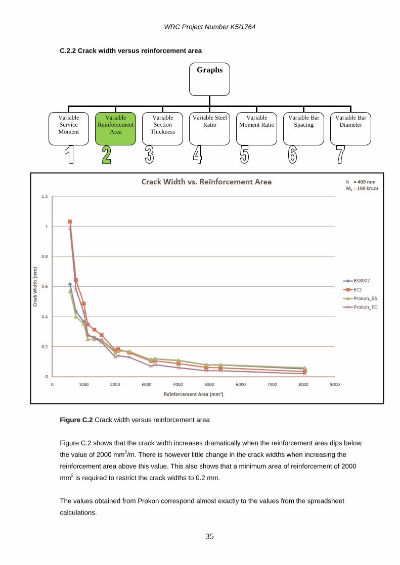
Figure C.2 Crack width versus reinforcement area
Figure C.2 shows that the crack width increases dramatically when the reinforcement area dips below
the value of 2000 mm2/m. There is however little change in the crack widths when increasing the
reinforcement area above this value. This also shows that a minimum area of reinforcement of 2000
mm2 is required to restrict the crack widths to 0.2 mm.
The values obtained from Prokon correspond almost exactly to the values from the spreadsheet
calculations.
Graphs
Variable
Service
Moment
Variable
Reinforcement
Area
Variable
Section
Thickness
Variable Bar
Diameter
Variable Bar
Spacing
Variable Steel
Ratio
Variable
Moment Ratio

WRC Project Number K5/1764
36
C.2.3 Crack width versus section thickness
Figure C.3 Crack width versus section thickness
Figure C.3 shows a great variance in the crack widths calculated by the different design formulae.
These graphs differ a lot due to the different assumptions made regarding the surface zones of
reinforcement.
A. BS 8007 specifies the following surface zone depths :
Graphs
Variable
Service
Moment
Variable
Reinforcement
Area
Variable
Section
Thickness
Variable Bar
Diameter
Variable Bar
Spacing
Variable
Moment Ratio
Variable Steel
Ratio
WRC Project Number K5/1764
37
For h < 500 mm, assume each reinforcement face controls h/2 depth of concrete. Where h is the
total depth of the slab.
For h > 500 mm, assume each reinforcement face controls 250 mm depth of concrete, ignoring
any central core beyond this surface depth.
B. prEN 1992-3 specifies :
The effective tension area should be taken as having a depth equal to 2.5 times the distance from the
tension face of the concrete to the centroid of the reinforcement, although for slabs the depth of this
effective area should be limited to (h-x)/3 where x is the depth to the neutral axis. An overall upper limit
of h/2 also applies.
This means that the surface zone depth is the minimum value of:
2.5 x (h-d)
(h-x)/3
h/2

WRC Project Number K5/1764
38
Graphs
Variable
Service
Moment
Variable
Reinforcement
Area
Variable
Section
Thickness
Variable Bar
Diameter
Variable Bar
Spacing
Variable
Moment Ratio
Variable Steel
Ratio
C.2.4 Crack width versus steel ratio
Figure C.4 Crack width versus steel ratio
Figure C.4 shows that the values obtained from the two different codes vary considerably at higher steel
ratios where the area of steel required exceeds the area of steel provided.
The Prokon values from the two codes however correspond to their respective values from the
spreadsheet.
This graph shows that a steel ratio of 0.5 is required to restrict the crack widths to a value of 0.2 mm.
WRC Project Number K5/1764
39
Graphs
Variable
Service
Moment
Variable
Reinforcement
Area
Variable
Section
Thickness
Variable Bar
Diameter
Variable Bar
Spacing
Variable
Moment Ratio
Variable Steel
Ratio
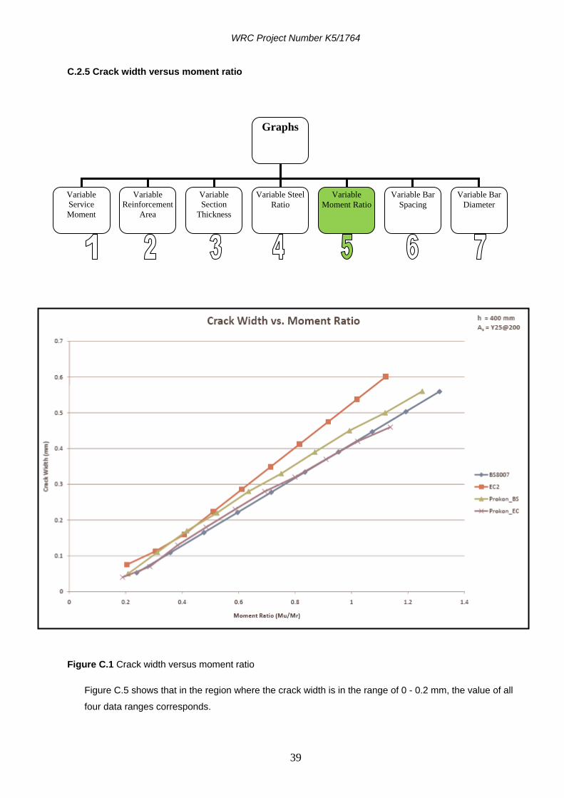
C.2.5 Crack width versus moment ratio
Figure C.1 Crack width versus moment ratio
Figure C.5 shows that in the region where the crack width is in the range of 0 - 0.2 mm, the value of all
four data ranges corresponds.
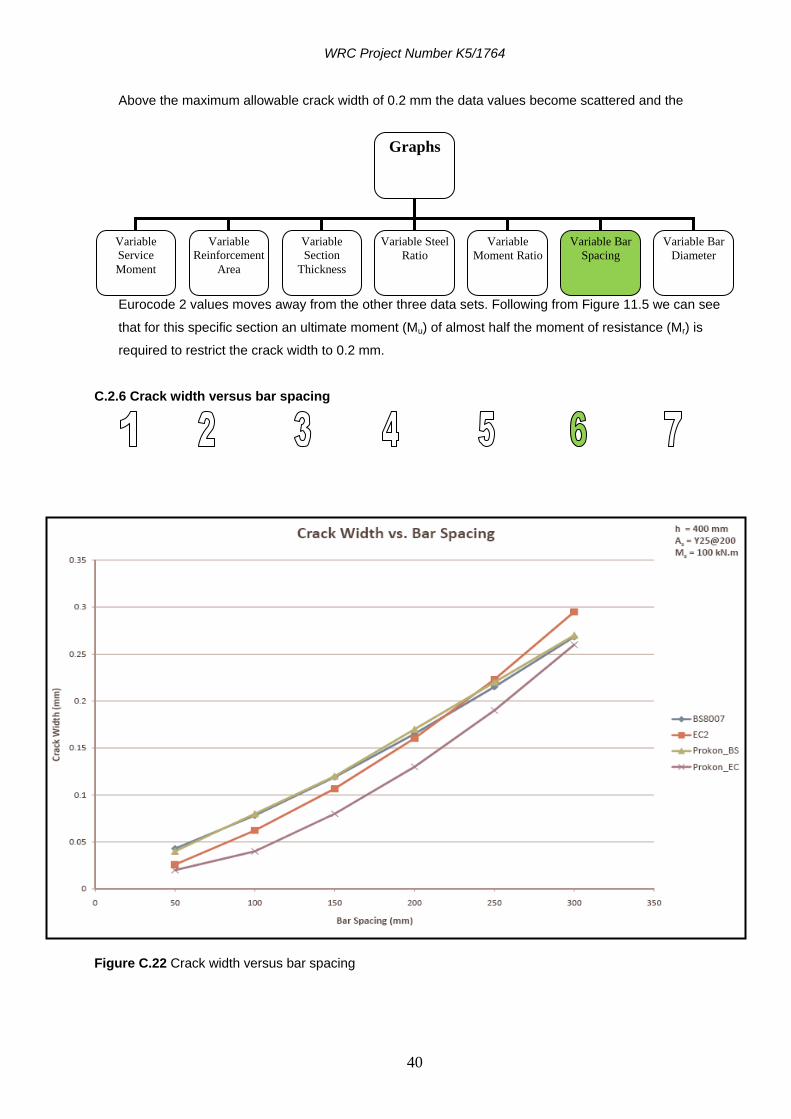
WRC Project Number K5/1764
40
Graphs
Variable
Service
Moment
Variable
Reinforcement
Area
Variable
Section
Thickness
Variable Bar
Diameter
Variable Bar
Spacing
Variable
Moment Ratio
Variable Steel
Ratio
Above the maximum allowable crack width of 0.2 mm the data values become scattered and the
Eurocode 2 values moves away from the other three data sets. Following from Figure 11.5 we can see
that for this specific section an ultimate moment (Mu) of almost half the moment of resistance (Mr) is
required to restrict the crack width to 0.2 mm.
C.2.6 Crack width versus bar spacing
Figure C.22 Crack width versus bar spacing

WRC Project Number K5/1764
41
Graphs
Variable
Service
Moment
Variable
Reinforcement
Area
Variable
Section
Thickness
Variable Bar
Diameter
Variable Bar
Spacing
Variable
Moment Ratio
Variable Steel
Ratio
From Figure C.6 it is apparent that all four data sets exhibit an almost exponential trend at which the
crack width changes relative to the spacing of the reinforcement bars.
Again, the Eurocode 2 values obtained from Prokon does not match the values of the other three data
sets. At a crack width of 0.2 mm the other three data sets lie on the same line. This figure also shows
that for this section a maximum bar spacing of 250 mm is allowed to restrict the crack widths to 0.2 mm.
C.2.7 Crack width versus bar diameter
Figure C.3 Crack width versus bar diameter

WRC Project Number K5/1764
42
For smaller bar diameters Eurocode 2 predicts larger crack widths than calculated with BS 8007.
The Prokon values almost exactly match the values from the spreadsheets.
Following from Figure C.7 it seems that the maximum allowable bar diameter, to restrict crack widths to
0.2 mm, is a 25 mm bar for this specific concrete section.

WRC Project Number K5/1764
43
ANNEXURE D
WORKSHOP HELD IN STELLENBOSCH ON 17 OCTOBER 2007

WRC Project Number K5/1764
44
A CODE FOR THE DESIGN OF WATER RETAINING STRUCTURES IN SOUTH AFRICA
WORKSHOP 17 OCTOBER 2007
PROGRAM 17 October 2007 : 08h15 : Coffee available 08h30 : Welcome and introductions : 08h40 : Introduction and overview of research project Jan Wium, University of Stellenbosch 08h55 : Practice in KwaZulu-Natal : A client’s perspective Simon Scruton, City of Durban 09h10 : Practice in KwaZulu-Natal : A designer’s perspective Selvan Naidu, Naidu Consulting 09h25 : Practice in Gauteng : A client’s perspective Jan Kruger, Tshwane City Council 09h40 : Practice in Gauteng : A contractor’s perspective Werner Jerling, Stefanutti & Bressan Civils (Pty) Ltd 10h00 : Tea 10h30 : Practice in Gauteng : A designers perspective Jan Wium for Erhard Kruger, HGK Consulting 10h40 : Practice in the Western Cape : A client’s perspective Arne Singels, City of Cape Town 10h55 : Practice in the Western Cape : A contractor’s perspective Alex Pospech, CSV Construction 11h10 : Practice in the Western Cape : A designer’s perspective Jan Wium for Hennie Niehaus, Ninham Shand 11h40 : Crack width calculations to BS8007 and EN 1992-3 Christina Mcleod, University of KwaZulu-Natal 11h55 : Reliability of design for water retaining structures Johan Retief, University of Stellenbosch 12h15 : Discussion All 13h00 : Lunch 13h45 – 14h30 : Summary and closure
WRC Project Number K5/1764
45
D.3 Summary of workshop held at the University of Stellenbosch
A brief summary of the views and concerns which was raised at the Workshop on 17 October 2007 at the
University of Stellenbosch is given below.
D.3.1 Mr. S Scruton. City of Durban : Client.
No thin walled or floating roof used on reservoirs.
Precast concrete only used for chamber roofs.
Bostik ditsit used to seal roof slabs at joints.
Access hatches 1 big and 1 small.
Vela VKE provides asset management program to eThekwini that stores attribute of all reservoir.
Vandalism is a big problem with fences and hatches.
Two types of reservoirs: Urban and Rural.
Need to implement sieves at inlet to reduce debris in reservoir.
eThekwini monitors all reservoirs on a 24 hour basis (fiber optics also used) with GSM loggers that react
on alerts.
D.3.2 Mr. S Naidu. Naidu Consulting : Designer
Temperatures used T1 = 40˚c and T2 = 30˚c.
Roof covering with stone for long term creep effects (in rural areas people steal the rock).
Curing methods: Fog sprays and hessian wrapped in plastic sheeting.
Gateway traffic circle is a big underground 3.2 Ml reservoir.
D.3.3 Mr. W Jerling. Stefanutti & Bressan Civils – Johannesburg : Contractor.
Dome roof is 10 % more expensive than flat roof.
No specification for pre-cast reservoirs.
No maintenance record for pre-cast reservoirs.
Testing of structures should be better specified.
Not all contractors have good quality control systems in place.
Good, skilled laborers are extremely had to find.
Mines are a potential for construction of water retaining structures where contractors and designers are
often used with insufficient experience.
Be careful of sealing materials like xypex and hypalon bandages.
Subsoil drainages have two functions: i) pressure relief, ii) leak detection.
Leakage detection with different subsoil drains for different panel and manholes connected for each
drain to detect leaks.
Cost of curing with water is expensive in certain inland areas.
Waterbars : Rubber – difficult to place.
PVC – bend and difficult to hold in place.

WRC Project Number K5/1764
46
Stainless steel – not available everywhere.
Copper – expensive.
D.3.4 Mr. A Singels. City of Cape Town : Client.
Curing by painting on membrane to retain concrete internal moisture.
Reservoir at Plattekloof pre-cast beams and slabs used.
Last tender pre-cast slabs came out cheaper when compared to cast in-situ.
Slabs which are sloped should be cast with lower part first and upper part later, because concrete will
not get under waterstop of lower slab if done other way around.
D.3.5 Ms. Christina Mcleod. University of KwaZulu-Natal : Lecturer.
Eurocode does not cover: - Structures at very high or low temperatures.
- Does not touch subject of waterstops or jointing materials.
BS 8007:1987 does not necessarily cover aggressive water.
Eurocode is more specific to crack widths and classification of water tightness EN 1992-3.
D.3.6 Mr. H G Kruger : Consultant, Pretoria
BS 8007 does not provide a calculation method for crack width under bending and axial tension. A
method was published by Kruger and Atkinson in 2005.
Roof slab are not post tensioned for his designs
Pre-cast is not used.
Concrete specification is durability driven and not strength.
Materials used :
o marine structures : slagment and OPC
o Sewerage pump stations : OPC + PFA + silica fume blend
o All others : OPC + PFA
o (minimize the usage of slagment)
Design codes : BS 8007, BS 8100, New Zealand code
Temperatures used : own experience
Very little use of expansion joints to create maintenance free structures.
Sliding joints used between wall and base for post tensioned structures, also for roof slab and walls.
No curing compound allowed, only water curing.
A South African Code requires information on :
- heat of hydration
- relative humidities
- Temperatures
- Code commentary
- More sketches and less words
- Good contact with Robin Atkinson of the UK, specialist.
WRC Project Number K5/1764
47
D.3.7 Mr. H Niehaus : Consultant, Cape Town
Reinforced concrete, pre-stressed and pre-cast pre tensioned.
Generally use 35 MPa concrete, cement type CEM I (class 42.5) with a specification of 25% GGCS
(slagment) by mass. Minimum cement content as per SBS 1200G table 5.
Design codes used : BS 8007 with BS8110, using load factors from BS 8110. Crack widths using BS
8007 (either by hand or using software such as Prokon)
Temperature used in design is according to BS 8007. Some special tests were done for particular
projects.
Details that are used are in-house developed but based on BS 8007 information.
Construction problems relate mainly to :
o honeycombed concrete
o shrinkage cracking due to inadequate curing or insufficient expansion joints.