
The Design Space of Network Mobility -...
34
P. Zave, J. Rexford, “The Design Space of Network Mobility”, in H. Haddadi, O. Bonaventure (Eds.), Recent Advances in Networking, (2013), pp. 379-412. Licensed under a CC-BY-SA Creative Commons license. The Design Space of Network Mobility Pamela Zave Jennifer Rexford Abstract While the Internet is increasingly mobile, seamless mobility is difficult to implement at Internet scale. Over the years, standards bodies and the research community have introduced a large and confusing col- lection of mobility proposals that are difficult to compare. In this tutorial, we present these mobility proposals in a uniform framework, called the geomorphic view of networking. The geomorphic view shows that there are two distinct patterns for implementing mobility, each with its own range of design choices and cost-benefit trade-offs. We use these patterns to classify and explain a representative sample of mobility mechanisms, abstractly yet precisely. The patterns also serve as a basis for evaluating properties of these mechanisms such as resource costs and scalability, and for considering composition of mobility mechanisms. 1 Introduction The Internet is increasingly mobile. Users access Internet services from mobile devices that move from one wireless access point to another, or switch between WiFi and cellular network connectivity. Ubiquitous computing relies on sensors and actuators attached to vehicles, portable objects, and animals as well as people. Applications provide customers with application-level identities that can be used to reach them at whichever device they are currently using. Increasingly, software runs on virtual machines that can migrate from one physical server, or even one data center, to another. We define network mobility as the capability that allows a communicating entity to continue to com- municate over a network, despite the fact that its location at (or binding to) a lower-level communicating entity is changing. Further, we focus on so-called “seamless” mobility, in which the high-level entity’s communication channels are preserved throughout the change. It is important to note that this definition applies at all conceptual levels. A person can have an identifier as a communicating entity, and can be mobile by moving from one networked device to another. A device such as a cellphone can have an identifier, and can be mobile by moving from one network attachment point to another. An interface on a device, such as an Ethernet interface, can have an identifier and be mobile by moving within or between local area networks. In recent years, many mechanisms have emerged for supporting mobility. A recent survey [39] cites 22 Internet protocols dating from 1991 to 2009, including most prominently Mobile IPv4, Mobile IPv6, MSM-IP, HIP, MOBIKE, Cellular IP, HAWAII, ILNP, and LISP Mobile Node. In other contexts mobility is supported by: • Ethernet LANs and VLANs, which allow an interface to retain its IP address as the host moves within the LAN; • the scalable “flat” routing architectures SEATTLE [18], PortLand [21], VL2 [10], NVP [23], and Rbridges/TRILL [29, 36] that also naturally support routing to an interface that retains its addresses
Transcript of The Design Space of Network Mobility -...
P. Zave, J. Rexford, “The Design Space of Network Mobility”, in H. Haddadi, O. Bonaventure (Eds.), Recent Advances inNetworking, (2013), pp. 379-412. Licensed under a CC-BY-SA Creative Commons license.
The Design Space of Network Mobility
Pamela Zave Jennifer Rexford
Abstract
While the Internet is increasingly mobile, seamless mobility is difficult to implement at Internet scale.Over the years, standards bodies and the research community have introduced a large and confusing col-lection of mobility proposals that are difficult to compare. In this tutorial, we present these mobilityproposals in a uniform framework, called the geomorphic view of networking. The geomorphic viewshows that there are two distinct patterns for implementing mobility, each with its own range of designchoices and cost-benefit trade-offs. We use these patterns to classify and explain a representative sample ofmobility mechanisms, abstractly yet precisely. The patterns also serve as a basis for evaluating propertiesof these mechanisms such as resource costs and scalability, and for considering composition of mobilitymechanisms.
1 IntroductionThe Internet is increasingly mobile. Users access Internet services from mobile devices that move fromone wireless access point to another, or switch between WiFi and cellular network connectivity. Ubiquitouscomputing relies on sensors and actuators attached to vehicles, portable objects, and animals as well aspeople. Applications provide customers with application-level identities that can be used to reach them atwhichever device they are currently using. Increasingly, software runs on virtual machines that can migratefrom one physical server, or even one data center, to another.
We define network mobility as the capability that allows a communicating entity to continue to com-municate over a network, despite the fact that its location at (or binding to) a lower-level communicatingentity is changing. Further, we focus on so-called “seamless” mobility, in which the high-level entity’scommunication channels are preserved throughout the change.
It is important to note that this definition applies at all conceptual levels. A person can have an identifieras a communicating entity, and can be mobile by moving from one networked device to another. A devicesuch as a cellphone can have an identifier, and can be mobile by moving from one network attachment pointto another. An interface on a device, such as an Ethernet interface, can have an identifier and be mobile bymoving within or between local area networks.
In recent years, many mechanisms have emerged for supporting mobility. A recent survey [39] cites22 Internet protocols dating from 1991 to 2009, including most prominently Mobile IPv4, Mobile IPv6,MSM-IP, HIP, MOBIKE, Cellular IP, HAWAII, ILNP, and LISP Mobile Node. In other contexts mobility issupported by:
• Ethernet LANs and VLANs, which allow an interface to retain its IP address as the host moves withinthe LAN;
• the scalable “flat” routing architectures SEATTLE [18], PortLand [21], VL2 [10], NVP [23], andRbridges/TRILL [29, 36] that also naturally support routing to an interface that retains its addresses

as the host move;
• injecting the IP address of a mobile machine into existing routing protocols such as OSPF and BGP [1,16];
• the General Packet Radio Service (GPRS) Tunneling Protocol (GTP), which supports mobility in mostcellular networks;
• other research proposals including TCP Migrate [32], Serval [25], and the Internet Indirection Infras-tructure [35];
• application-level protocols such as the Session Initiation Protocol (SIP) [31].
Each well-known proposal tends to spawn a family of variants, so the total number is probably in the hun-dreds and growing.
These various mechanisms operate at different levels, and make different assumptions about naming,routing, session protocols, scale, security, and the cooperation of remote endpoints or multiple administra-tive domains. Because the community lacks a common framework for describing and comparing mobilitymechanisms, their relationships are poorly understood. Comparisons tend to be based on superficial char-acteristics rather than inherent ones. Quantitative comparison must be based on labor-intensive prototypingand measurement or simulation.
This book chapter has two goals:
• To describe and compare existing proposals for implementing mobility.
• To map out a design space in which new mobility mechanisms can be discovered, evaluated, andexploited.
To achieve these goals, we explain mobility in a new way. We begin by defining a common frameworkfor describing network architectures. This framework is called the geomorphic view of networking, and isintroduced in Section 2.
The geomorphic view has been developed to be simple, modular, comprehensive, and formalizable. Itsupports the first goal by providing a precise, unique description of each mobility mechanism that omitsinessential detail while exposing subtle differences and important engineering trade-offs.
The common framework supports the second goal in several ways. It allows us to generalize over theimplementations of mobility, showing that they are all instances of two major patterns. It also allows us tounderstand how different instances of the mobility patterns at different places in a network architecture canbe composed, generating a potentially large design space to be explored.
Section 3 of this chapter introduces the two major patterns—dynamic-routing mobility and session-location mobility—for implementing mobility. If they are both implemented within an IP layer, the dif-ference centers on whether a mobile machine retains its IP address when it moves, or changes its IP addressand updates its correspondents. Each pattern has a completely different set of subsidiary design decisionsand resource costs.
The next sections use the patterns to describe and compare many of the most important proposals formobility. Sections 4 and 5 compare different ways to implement dynamic-routing mobility, with a non-hierarchical name space (e.g., MAC addresses in a local area network) or a hierarchical name space (e.g., IPaddresses in the wide area), respectively. Section 6 compares four prominent protocols for session-locationmobility at different stages in the IETF standardization process.
Section 7 of the chapter turns to a more systematic exploration of the design space, first showing thatthere may be some freedom concerning where in an architecture a particular kind of mobility is handled.The section also discusses composition of mobility mechanisms. As an example, we illustrate how MobileIPv6 is a composition of both the dynamic-routing mobility and session-location mobility design patterns.
Finally, Section 8 surveys several topics closely related to mobility, including multihoming, anycastservices, site mobility, incremental deployment of mobility protocols, and security issues for mobility. Thechapter ends with a brief conclusion outlining several more advanced areas of study.
2 The geomorphic view of networkingThe geomorphic view of networking was originally inspired by the work of Day [7], although we have mademany changes and additions in both content and presentation. In this common framework for describingnetworks, the module is a layer, and a network architecture is a hierarchy of layers.
2.1 Comparison with the Internet and OSI modelsLayers may seem familiar and obvious because both the classic Internet architecture [6] and the OSI refer-ence model [14] also describe network architecture as a hierarchy of layers. However, our concept of a layeris very different. As a preview of this section, our layer hierarchies differ from these earlier ones in at leastfour ways:
• The classic Internet architecture and the OSI reference model both have a fixed number of levels. In ageomorphic layer hierarchy, there can be any number of levels.
• In the earlier models, there is only one layer on each level, so there is no distinction between layer andlevel. In a geomorphic hierarchy, there can be multiple layers on the same level.
• In the earlier models, each layer has a specific function that is distinct from the functions of otherlayers. In the geomorphic view each layer is a microcosm of networking, containing all of the basiccomponents and functions in some form. In different layer instances there are different versions ofthese basic ingredients, used at different levels, with different scopes, and for different purposes.
• Most people interpret the earlier models as describing the data plane of networking only. The controlplane is seen as separate and not modularized in the same way. In the geomorphic view, each layer—being a microcosm of networking—has a data plane and a control plane. Layers decompose bothplanes into modules.
Figure 1 illustrates these differences, and also shows how the “geomorphic” view got its name. The complexarrangement of layers, with overlapping, abutting, and bulging shapes, can resemble the complex arrange-ment of layers in the earth’s crust.
2.2 Components of a layerA layer has members, each of which has a unique and persistent name within the layer. For example, Figure 2is a snapshot of a layer with five members, each having a capital letter as a name. In general a member is aconcurrent process, i.e., a locus of state and control with the potential for autonomous action.
The members of a layer communicate with each other through links, shown by lines in Figure 2. A linkis a communication channel.

Figure 1: Arrangement of layers in the classic Internet architecture (left), the geomorphic view (middle),and the earth’s crust (right).
A B
C D E
Figure 2: Members and links of a layer.
One of the two primary functions of a layer is to enable members to send messages to each other. Thisfunction is accomplished by a forwarding protocol, which runs in all members and has operations for sendingand receiving messages over the links.
In general, a layer does not have a link between each pair of members. Such a layer needs routesindicating how one member can reach another through links and intermediate members. For example, (A, B,D, E ) is a route from A to E. If B receives a message that is destined for E, its forwarding protocol uses theroute information to forward the message to D on its way to E.
The routes are shared state of the layer, and a simple geomorphic description need say no more aboutthem. To provide more realistic detail, in a real layer the routes information is often distributed over for-warding tables found in the individual members.
The other primary function of a layer is to implement enriched end-to-end communication services on topof its bare message transmission. This function is carried out by a session protocol. The forwarding protocolcan be unreliable, especially if links are dynamic and the current routes are obsolete. A session protocol canprovide services including reliability, FIFO delivery, and quality-of-service guarantees. Figure 3 shows asession between endpoints a and e of the lower layer.
A channel is an instance of a communication service. Both links and sessions are channels. A layer canimplement its own links internally, and a layer can implement its sessions for the benefit of its own members.
Most commonly, however, a link in one layer is implemented by a session in another layer, as shown inFigure 3, placing the other layer lower in the “uses” hierarchy. If an underlay (lower layer) is implementinga link for an overlay (higher layer), then the basic attributes of the channel must be stored in the states ofboth layers. In the overlay, the channel object is one of its links. In the underlay, the channel object is one ofits sessions. There must be two names for the sets of channels of interest to a layer, because a typical layerboth uses links and implements sessions.
For a link in an overlay to be implemented by a session in an underlay, both endpoint machines must havemembers in both layers, as shown in Figure 3. The boundary of a machine is the boundary of an operating

registration
processes onone machine
session
A E
a edb
link
link
Figure 3: Implementation of a link in an overlay by a session in an underlay.
system that provides fast, reliable communication between members of different layers on the machine.This fast, reliable operating-system communication is the foundation on which networked communicationis built.1
The relation between an overlay member and an underlay member on the same machine is called regis-tration. Registrations must be stored in the state of both layers. In the overlay a registration is recorded as anattachment, which says that the overlay member is attached to the network through a particular lower layer.In the underlay a registration is recorded as a location, which says that a particular member of a particularoverlay is attached to the network at a particular member (its location) of this layer.
The session protocol creates and maintains sessions data in its layer, and uses locations data. For exam-ple, in Figure 3, A sent a request to a for a session with E. To create this session, a learned from its layer’slocations that E is currently located at e. Messages sent from A to E through the link in the overlay travelthrough a, b, d, and e; the first and last steps uses operating-system communication, while the middle threesteps use networked communication.
All the major components of a layer are shown in Figure 4. The forwarding and session protocolsperform the two primary functions of the layer. These protocols and their operations are collectively knownas the “data plane” of the layer. The network’s data plane also includes the inter-layer interfaces throughwhich the endpoints of an implemented link transfer messages to and from the implementing session.
There are six major state components, all of which can be dynamic. We have seen that the sessionprotocol creates and maintains sessions; the other five are created and maintained by their own maintenancealgorithms. The state and algorithms are collectively known as the “control plane” of the layer. Note thatthe network’s control plane also includes the inter-layer interfaces through which the control algorithmscommunicate.
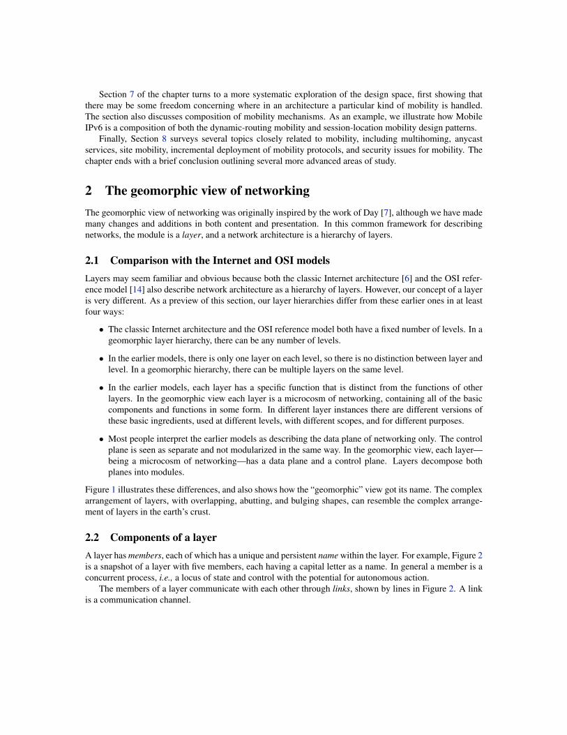
2.3 Layers within a network architectureFigure 5 shows a geomorphic view of the classic Internet architecture. The scope of a layer is its set ofpotential members. For example, at the top level of the hierarchy, there are two application layers. The
1Although layer members have been described as concurrent processes, they are not usually “processes” as defined by the operatingsystem; processes in an operating system have many more properties and associations than layer members do. A virtual machine canbe regarded as a machine, in which case communication through the hypervisor and soft switch of the physical machine is regarded asnetworked communication.

primary function state component maintenance algorithm
member algorithmlocation algorithm
attachment algorithmlink algorithmrouting algorithm
memberslocationssessionsattachmentslinksroutes
session protocol
forwarding protocol
Figure 4: Major components of a layer. Arrows show which protocol or algorithm writes a state component.
scope of each layer is the set of potential processes running software for that application. These layers arepictured as overlapping because the horizontal dimension is an approximation of geographical space, andboth applications can have members world-wide. In particular, the registration lines in the diagram showthat each application has a member on one particular machine.
In the middle level of the hierarchy there is a single layer called the “Internet core.” Its members are theIP interfaces of networked machines. In this layer, IP (the “network layer” of the classic Internet architecture)is the forwarding protocol, and TCP and UDP (the “transport layer” of the classic Internet architecture) arevariants of the session protocol.
At the bottom level of the hierarchy there are local area networks (LANs) with local scopes. Each LANmember is an interface appropriate to the type of LAN. For example, for an Ethernet LAN, the members arethe Ethernet interfaces of machines. Figure 5 illustrates the point, made in the preview of this section, thatin the geomorphic view there can be multiple layers at one level of the “uses” hierarchy.
Note that every member of the Internet core is attached to a member of a layer at the bottom level. Noteespecially that for two members of the Internet core layer to be linked, both of those members must beattached to the same layer at a lower level, so that the lower layer can implement the link. This observationis important for understanding mobility. A gateway in the Internet core layer is attached to multiple LANs,so it can forward messages from one LAN to another.
Because layers instantiated at different levels have different purposes, they have different versions ofthe common components enumerated in Figure 4. For one example, the best-known routing algorithms arefound in the Internet core, where their purpose is reachability. Now consider a middleware layer, above theInternet core, offering cloud services and other facilities for enterprise computing. To provide security, thislayer might have routing that ensures that all messages to a particular destination pass through a particularfiltering server. Thus this layer has its own routing (control plane), separate from Internet routing. One ofthe major purposes of its routing is enterprise-specific security.
This example illustrates the points, made in the preview of this section, that in the geomorphic view thenumber of levels is not fixed (the middleware layer need not be present for the Internet to work), and thateach layer can contain its own version of any basic function or component of networking (such as routing).In some layers, where a particular function or component is not needed, its presence is vestigial.
For another example of a basic function with different forms in different layers, low-level layers suchas Ethernet LANs provide broadcast as a communication service. In geomorphic terms, channels (links andsessions) can be multi-point as well as point-to-point. The main services provided by the Internet core arepoint-to-point, while an application layer might implement its own multi-party communication service.2
2For simplicity, in the remainder of this chapter, all communication channels are assumed to be point-to-point. This is sufficient fora study of mobility.
LAN 1 LAN 2 LAN 3
1 2 2 3
gateway gateway
Application 1
Application 2
Internet core
Figure 5: Geomorphic view of the classic Internet architecture. Internet links are labeled with the LAN thatimplements them.
Today’s Internet is host to many customized architectures running simultaneously [30, 33]. Middlewareis an important part of the ecosystem, while cloud services and virtual private networks add extra layers to theclassic Internet architecture. It is self-evident that fixed layer structures cannot describe these architecturesadequately. The geomorphic view is intended not only to describe them, but also to generate a design spaceincluding many others not yet explored.
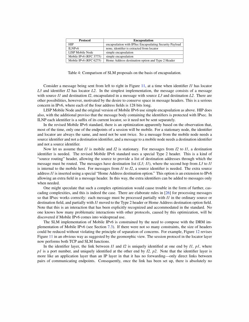
2.4 Layers and mobilityIf asked to define network mobility, most people would say something like, “A mobile device continues tohave network connectivity as it moves geographically.” For a simple Internet example, we can imagine alaptop that detaches from one edge subnetwork, where it has one IP address, and re-attaches to another edgesubnetwork, where it has another IP address.
No layering is required to understand this scenario. At the same time, technologically the scenariois indistinguishable from a scenario in which one laptop is tossed into a deep lake and another laptop ispurchased new.
Clearly mobility is more than this. As the mobile device detaches and re-attaches, we expect it to retainsome identity and credentials, so that it can be reached in some of the same ways as before, and has someof the same rights and capabilities as before. The identity that is preserved is its membership in some layer,which must not change. What does change is the attachment of this identifying process to some process insome lower layer.
The left column of Figure 13 (which appears later, in Section 7.2) shows the two forms that this changeof attachment can take. In the top picture, a process m changes its registration from one member of a lower

layer to another member of the same layer. The name m might be an application name, and a1 and a2 mightbe IP addresses in an Internet core layer. In the bottom picture, m changes its registration from a member ofone lower layer to a member of another lower layer. Here m might be an IP address, and a1 and a2 might bemembers of two different LANs.
This shows that layering is an intrinsic part of the study of mobility, because it explains what stays thesame and what changes. It will help us understand how a person can call a friend’s cellphone, even thoughthat friend has traveled hundreds of miles since the last call.
Even this is not sufficient to explain, however, how a person can talk to a friend’s cellphone whilethe friend is traveling hundreds of miles. To explain this aspect of mobility it is necessary to focus onthe communication channel that is being preserved across mobility events. As presented in Section 2.2, acommunication channel is most often used in one layer, where it is called a link, and implemented in a lowerlayer, where it is called a session. Here is another place where layering is intrinsic to the study of mobility,explaining that the layer that benefits from mobility is usually not the layer that has the responsibility ofimplementing it.
To summarize, there are two relationships on layer pairs that are important in mobility. There is adynamic registration relationship between an overlay with a mobile member and the underlays to which thatmember of the overlay is attached over time. There is an implementation relationship between an overlaywith a link and the underlay whose session implements that link. Two overlay/underlay pairs—in any giveninstance of mobility, they must be the same overlay and underlay, right?
Wrong. Section 3 will show that there are two patterns for mobility. In one pattern the layer pairscoincide, and in the other they are different. People are often confused by mobility because it is oftenover-simplified. Mobility is easy to over-simplify when one is not explicit about the layers involved.
2.5 Mobility in the wildIt might be said that the problem with mobility is not too few proposals, but too many. As mentioned in theintroduction, the total number is probably in the hundreds and growing.
In this chapter, the geomorphic view will provide a descriptive framework that imposes some order onthis chaotic design space. This works because every mobility proposal has a unique description in terms oflayers in the geomorphic view.
Unique description is achieved only because the geomorphic view is precisely defined and preciselyused. For one example, in the geomorphic view there is one name space per layer. If any proposal has twodifferent names for the same machine, one higher-level and one lower-level, then those names must be inthe name spaces of two different layers. For another example, in the geomorphic view there is no tunneling.Tunneling is evidence that there are two distinct layers: a higher layer in which the “tunnel” is a link, and alower layer that implements the link.
As a result, a geomorphic description of a network architecture might have more layers than a differentdescription, and some components of some layers might be vestigial. This is a cost, but in return we getmany benefits, even beyond the benefits of having a unique and comparable description of each proposal:
• Each layer is simpler, with a minimum of ad hoc complications.
• Proposals that might seem very diverse fall into a few recognizable patterns that apply at any level ofthe network stack.
• We can identify opportunities for re-use of formal models, formal analysis, and implementation code.

• Mobility is not the only networking challenge. If other complex mechanisms are also described interms of the geomorphic view, we can make sure that they interact correctly.
Furthermore, redundancies in a description or model can be removed by optimization in an implementationphase. The trick is to understand and analyze the model first, then use the analysis to determine whichoptimizations are safe.
This approach leads to differences from other literature on mobility. As exemplified by [2], it is commonfor mobility proposals to be classified according to the layer of the classic Internet architecture where they areimplemented. In contrast, we emphasize that each specific proposal is an instance of a general pattern, andthat the general pattern can be used at any level of a network architecture. Comparisons between ideas areless subjective, because they are based on a common framework that exposes real similarities and differences,even when obscured by incidentals of language and application.
3 Two patterns for implementing mobilityIn this section we show that there are two completely different patterns for implementing mobility. Theydiffer in where the change of attachment appears with respect to the implementing layer, in which algorithmsand protocols of the implementing layer are involved in implementing mobility, and in which parts of theshared state of the implementing layer are altered. They also differ in their detailed design decisions, and intheir cost, performance, and scalability issues.
Not only are these patterns non-overlapping, they also completely cover all implementations of mobility,in the sense that each implementation either follows one pattern or is clearly a composition of the twopatterns.
3.1 Dynamic-routing mobilityFigure 6 has two stages depicting the effect of mobility on an inter-layer channel. Recall that the channel isa link in the state of the layer that uses it, and a session in the state of the layer that implements it; its higherendpoints are members in the user layer, while its lower endpoints are members in the implementing layer.
The precise site of mobility here is the lower endpoint A. In Stage 1 A is registered at a1 in Underlay 1.a1 and A are connected to the rest of their layers through Links 1 and 2, respectively. Link 2 is implementedby Underlay 1.
Between Stage 1 and Stage 2 Link 1 stops working, possibly because the machine on which A and a1reside has been unplugged from a wired subnetwork, or has moved out of range of a wireless subnetwork.In a cascading sequence of events, Link 1 is destroyed, Link 2 is destroyed, and the registration of A at a1 isdestroyed. A is now disconnected from the rest of its layer.
Eventually the mobile machine may become plugged into another wired subnetwork or enter the rangeof another wireless subnetwork, as shown in Stage 2. In a cascading sequence of events, member a2 (whichis the mobile machine’s member in the new Underlay 2) connects to the rest of its layer through Link 3, Abecomes attached to new location a2, and new Link 4 is created in the mobility layer and implemented byUnderlay 2. Note that A is now linked to C rather than B; this change is necessary because C is attached toUnderlay 2 and B is not.
Between Stages 1 and 2 there may be an interval during which A has no connection with the rest of itslayer. There may also be an interval in which Stages 1 and 2 overlap, so that A is temporarily attached toboth underlays.

user layer
implementing layer implementing layer
link
session
user layer
link
2
session
4
A E A E
A B D E A C D E
ba1 f1
Underlay 1 ca2 g
3
Underlay 2
Figure 6: Two stages in an instance of dynamic-routing mobility.
The hard problem to be solved in Figure 6 is that even after A is again reachable by other members of itslayer such as D and E, they do not know how to find it because the routes to it are obsolete. Dynamic-routingmobility relies on the routing algorithm of the layer, which must learn about new links, recompute routes,and update forwarding tables. After this is accomplished, D will know that it can reach A by forwarding toC.
There are three ways in which actual dynamic-routing mobility can differ from the example in Figure 6.Fortunately, none of them affect what the implementation has to do, so none of them need be discussedseparately. First, the new attachment a2 could be in the same layer as a1, rather than in a different layer.Because a1 and a2 are different locations, after the move A is probably linked to a different member of itsown layer, even though the new link is implemented by the same lower layer as before.
Second, in Figure 6 the mobile member A has only one attachment and one necessary link. As shown inFigure 5, members such as gateways have multiple simultaneous attachments to different underlays. Becauseeach such attachment is necessary for the gateway’s purpose and supports its own link or links, the mobilityof each attachment is a separate problem to be solved.
Third, occasionally a layer implements sessions for the benefit of its own members, rather than as aservice to a higher user layer. In this case there is no A or E, and the beneficiaries of the mobility implemen-tation are A and E.
A router is a member of a layer that receives and forwards messages not destined for itself, whether itsends and receives messages on its own behalf or not. A forwarding table is a distributed copy of someof the routes state component of a layer. Implementations of dynamic-routing mobility incur four kinds ofresource cost:
• storage cost is the cost of storing routes to mobile members, in the forwarding tables of all the routersthat need them;
• update cost is the cost of updating the stored routes as mobile members move;

user layer
implementing layer implementing layer
link
session
user layer
link
session
A E A E
A1 B D E A2 C D E
Figure 7: Two stages in an instance of session-location mobility.
• path cost is the cost of longer or more congested message paths due to mobility;
• handoff latency is the message delay caused by a move.
These costs will be discussed further in Section 3.3.The primary issue in implementing dynamic-routing mobility (DRM) is that large layers such as the
classic Internet core achieve scalability through a hierarchical name space. In the Internet core, names (IPaddresses) are organized into a hierarchy based on geographical, topological, and administrative factors. Alayer member is assigned a name based on its location in this hierarchy. Subtrees in the hierarchy correspondto blocks of names, and routing scales because it operates on aggregated blocks rather than individual names.Mobility violates the rules of this scheme, because a mobile member retains its name as it moves acrossthe boundaries of the hierarchy. If implemented naively, it would require a large number of entries in theforwarding table of each IP router for individual mobile machines.
This issue is so important that the design decisions made to implement DRM are completely differentin hierarchical and non-hierarchical layers. For that reason, we have divided examples of DRM into twosections (Sections 4 and 5).
3.2 Session-location mobilityFigure 7 has the same two stages as Figure 6. The most important difference is that A’s location in theimplementing layer changes from A1 to A2, rather than staying the same as it did in Figure 6. In geomorphicterms, the mobile machine’s representative in the implementing layer (with name A1) has died, and has beenreborn as a member of the implementing layer with name A2.
This is a natural occurrence in a layer with a hierarchical name space. It should be familiar from observ-ing what happens when a laptop with an IP address A1 moves to a new subnetwork of the Internet, and getsa new IP address A2 from DHCP. The laptop cannot continue to use A1 in the new subnetwork, because A1is not in the subnetwork’s address block.
DHCP alone is not sufficient to implement mobility, however. As explained in Section 2.4 and shownin Figure 7, the strongest form of mobility requires preserving the communication channel in the user layer.The bulk of the work of implementing session-location mobility lies in ensuring that A’s correspondents

know that it is now located at A2 rather than A1. Each lower endpoint that was participating in a sessionwith A1 on behalf of A must be informed that it should now be corresponding with A2 instead.
As explained in Section 2.2, when an underlay is implementing a channel for an overlay, the initiatinglower endpoint must be able to look up the location of the accepting higher endpoint in the underlay, so thatit can send messages to it. This means that there must be a globally accessible copy of the locations mappingin the layer. Session-location mobility also requires updating this mapping when a higher endpoint moves.
Generally the fastest handoffs are achieved when a new lower endpoint sends updates directly to all itscorrespondent lower endpoints (in addition to updating the locations mapping). This requires, of course,that the new lower endpoint have the correct name of the lower endpoint at the other end of each session.
Interesting behavior arises if both ends of a session move concurrently. Neither lower endpoint will knowthe new name of the far endpoint, so neither can send an update to the other. In this simultaneous handoffscenario a mobile endpoint, finding that it cannot reach a far endpoint to update it, will suspect that the farendpoint has moved also. Both endpoints must fall back on lookup from the locations mapping to get thenew location of the far endpoint.
As with Figure 6, the two stages in Figure 7 might have a gap between them or might overlap. If theyoverlap, there will be an interval during which A has two attachments in the same layer.
In Figure 7 the underlays are not shown, although they probably look similar to those in Figure 6. Mostlikely there is an underlay member a1 that is destroyed, and an underlay member a2 that is created. Thereis no mobility observable at this level, however, because A1 is attached to a1 in Underlay 1 throughout itslifetime, and A2 is attached to a2 in Underlay 2 throughout its lifetime. The only mobility that is observableis A’s change of attachment from A1 to A2.
Strictly speaking some dynamic routing could be involved in session-location mobility, because A2 is anew member of the layer and there must be routes to it. In practice this is rarely an issue, because the nameA2 is part of some larger block to which routes already exist.
Like DRM, session-location mobility (SLM) has storage costs, update costs, and handoff latency. Thestorage costs are the costs of maintaining a scalable implementation of locations. The update costs are thecosts of updating locations and current correspondents when a member moves.
Implementations of SLM vary in a number of ways (see Section 6), although no one variation is asimportant as the hierarchical versus non-hierarchical variation for DRM.
3.3 Major differences between the patternsThere are obvious structural differences between the two patterns:
• In DRM the change of attachment appears between the implementing layer and the level below it,while in SLM the change of attachment appears between the user layer and the implementing layer(see Figures 6 and 7).
• In DRM the bulk of the work is performed by the routing algorithm, while in SLM the bulk of thework is performed by the session protocol and location algorithm (see Figure 4).
• In DRM the major state components that change are attachments, links, and routes (see Figure 4). InSLM the major state components that change are locations and sessions.
These structural differences prove that the two patterns are fundamentally different.In attempting to understand mobility mechanisms, people are sometimes confused by the fact that routes
(changed by DRM) and locations (changed by SLM) are both mappings. The locations mapping is usuallyimplemented by a shared global data structure called a directory. The routes mapping is usually distributed

across the forwarding tables of the routers, but is occasionally implemented as a directory. The result is thatdirectories are sometimes used in both DRM and SLM implementations.
This similarity is superficial because it does not tell us the most important thing about these mappings,which is what they mean in terms of network architecture. The mappings used in DRM and SLM are alwaysfundamentally different, and can always be distinguished from one another. As mentioned in Section 3.1,routes is a peer-to-peer or intra-layer mapping: at each router, entries in the forwarding table map eachdestination name to a member, link, or path in the same layer. Locations, on the other hand, is always aninter-layer mapping, mapping names in a higher layer to names in a lower layer.
In describing mobility mechanisms, people often focus on the “identifier-locator split.” This may beuseful intuition, but should be interpreted carefully. In an episode of mobility there is always a layer memberthat retains its identity (the “identifier”), and two members at a lower level, where the attachment of theidentifier moves from one to the other (the “locators”). The identifier-locator split does not distinguish DRMfrom SLM, although in the two patterns the identifiers and locators appear at different levels. In addition, itis important to remember that these terms are relative, as mobility can occur anywhere in a layer hierarchy.
On the surface, it may seem that DRM should be called “in-network mobility” or the like, while SLMshould be called “end-to-end mobility” or the like. This reflects a misunderstanding of how general thepatterns are, and how freely they can be applied at different levels. For one example, consider an applicationlayer whose members run only on Internet hosts. The members include user clients and named services.The layer could have its own dynamic, application-specific routing to services, which allows services to bereached even though they move from server to server. This instance of DRM is not “in network” from mostpeoples’ perspective. For another example, an Internet router might itself be mobile, and might have someof its links to other Internet routers preserved as it moves by session-location mobility at a lower level. Thisinstance of SLM does not involve any endpoints according to most peoples’ perspective.
Obviously a quantitative comparison between two mobility implementations cannot be made withoutimplementation details and a profile of the expected load. Nevertheless, it is possible to make some generalcomparisons between the two patterns based on their potential strengths and weaknesses. We say “potential”because any characteristic, whether positive or negative, can be irrelevant in some situations.
The greatest potential weakness of DRM is its storage, update, and path costs. Normally routing in-formation is different in different places, so there is a lot of it, it is spread widely across a layer, and it isexpensive to update. Attempts to economize on storage and update costs can lead to high path costs (seeSection 5), as messages travel further to be routed successfully. Path costs must be weighted heavily becauseevery message that travels on a channel is affected by its path cost, if any.
Locations are very different from routes because the result of a location query is usually the same nomatter which member is querying (in contrast to a route, which is different depending on where it is startingfrom), and because a location query is needed only at the beginning of a session and possibly after a move (incontrast to routes, which are consulted on every hop of every message). As a result, locations can be storedand updated much more cheaply than routes. For example, even a centralized directory would performadequately in many contexts. And even if lookup of a location is slow, we do not count it as a path costbecause the cost is incurred a few times for each channel rather than being built into the cost of transmittingeach message on the channel.
The greatest potential weakness of SLM is that it must be implemented with the participation of sessionendpoints. This means that deployment of an SLM mechanism requires new or upgraded mobile devices thatrun the SLM protocol for sending and receiving location updates. Full interoperation with legacy endpointscalls for expensive middleboxes. Security is a concern because endpoint devices can initiate updates of theglobal layer state.

root
Figure 8: Inter-switch links of an Ethernet LAN layer (left) and an overlay layer (right). The Ethernet linksare physical, while the overlay links are virtual.
Concerns such as software upgrading and security have attracted less attention with respect to DRM.This is because a layer can, in principle, be designed so that its members are partitioned into endpoints androuters, and only the routers need be aware of or participate in an implementation of DRM. In reality theseconcerns are ubiquitous in distributed computing, and can apply to routers as well.
4 Examples of dynamic-routing mobility in non-hierarchical layersDynamic-routing mobility is often used in LANs, which have smaller scopes and can function without ahierarchical name space. These LANs handle mobility naturally as part of the normal routing function, sinceend-points retain their addresses as they move and routing does not rely on location-dependent addressing.
4.1 Wired Ethernet LANsAn Ethernet LAN is a single layer. Its member processes are the Ethernet representatives of hosts (end-points) and switches (routers), and its names are MAC addresses. It has no pre-attachment requirements orconfiguration for hosts, which makes it “plug and play.”
The LAN offers both broadcast and point-to-point services to higher layers. In this brief section we donot consider these communication services further, so there will be no discussion of the layer’s sessions orlocations. Also, for simplicity, we will not extend the modeling into lower levels, so links in the Ethernetlayer are primitives.
An Ethernet layer has two kinds of links. There are point-to-point links between switches, each of whichis basically a wire between two machines. There are also shared media or buses. A bus delivers each messageto every machine on the bus, and is used to connect a switch to a set of hosts. Either kind of link can beidentified at each switch that uses it by the port on the switch’s machine to which it is attached.
The inter-switch links of the layer must form a bidirectional spanning tree (see Figure 8). Otherwise,when flooding is used (see below), the network could be overwhelmed by messages traveling on cycles.There are usually more physical links than needed for the spanning tree, but the extras can only be usedwhen other links fail and the spanning tree is recomputed.
Each switch has a forwarding table containing (MAC address, port) pairs. The port identifies the link onwhich the switch should forward messages destined for the MAC address. Each switch’s table is sparse and

is populated lazily by a routing algorithm called “MAC learning.” Upon receiving a message with a sourceMAC address that is not in its forwarding table, the switch adds to its table the MAC address and the link onwhich the message was received.
The forwarding algorithm of a switch is similarly simple. Upon receiving a message not destined foritself, the switch looks for the destination MAC address in its own forwarding table. If it finds an entry,it forwards the message on the designated link. If it does not find an entry, it “floods” by forwarding themessage on every link except the one on which it was received.
These mechanisms implement dynamic-routing mobility as an aspect of normal operation rather thanas a special case. When a host moves within the layer, it changes the link through which it is attached tothe layer. As soon as it sends messages, new routes to it begin to propagate through the layer. Obsoleteforwarding-table entries are removed when their time-to-live expires. Missing table entries are handled byflooding. Note that an entry might also be removed from a forwarding table because the table is full andspace for a newer entry is needed.
4.2 Ethernet overlaysSeveral recent designs [18, 10, 23] avoid flooding by forming an overlay topology that interconnects all ofthe edge switches, as shown on the right side of Figure 8. While the inter-switch links of an Ethernet arephysical and form a spanning tree, the inter-switch links of an overlay network are virtual and fully connectthe switches.
The virtual links are communication services implemented by a second, lower layer. For example,Figure 9 shows the path of a message from host Hv to host Hz (the lower-case letters stand for their MACaddresses). On each hop, the path is labeled with the source name above and the destination name below.The virtual hop between switches Sw and Sy in the overlay layer is implemented in the underlay, where themessage is encapsulated in a message with source w and destination y.
How are the virtual links in the overlay implemented by the underlay? The members of the underlaylayer are the switches only, not the hosts. Each switch’s name is the MAC address of its machine, just as inthe overlay, so there is no need for a locations state component to map one name to another. The membersof the underlay are stable and stationary. Routing is static except for failures, and the forwarding tables arefully populated. Because there is no flooding, there is no need to restrict the links to a spanning tree, andall of the physical links between switches can be fully utilized. The underlay can run an efficient routingprotocol, such as a link-state protocol, to compute a shortest path from one edge switch to another.
Routing in the overlay is unusual compared to routing in general, because every edge switch is directlylinked to every other edge switch. This means that an inter-switch route to a host can be identified simplyby the MAC address of the host’s edge switch, and is exactly the same no matter which switch needs theroute! Thus inter-switch routing is a mapping that is global within the layer. Note that, despite the use ofa single global directory, the mapping performed is indeed part of routing within the layer (i.e., the routesmapping), not a locations mapping between two layers. The underlay layer in Figure 9 exists to make therouting between the edge switches more scalable, not to implement the link between the two end-points.
As with Ethernet LANs, each switch has a routing table that is populated lazily (e.g., through MAClearning). The difference lies in what happens when a switch needs a route to an unknown destination.Rather than flooding, it looks the route up in a global routing directory.
When a host moves, the directory is updated with the new route to the host. The exact update mechanismdiffers from one overlay design to another, depending on whether mobility is planned (e.g., virtual-machinemigration in a data center) or unplanned (e.g., a mobile device moving within a campus). In a data cen-ter, a central controller that triggers virtual-machine migration can also update the directory with the new

Hv HzSy
Sy
Sw
Sw Sx
overlay
v v vz z z
w wy y
underlay
Figure 9: The path of a message through two layers and three switches.
route [10, 23]. If the directory cannot be informed in advance that a host is moving, the new local switchcan learn that a new device has connected and subsequently update the directory [18].
The routing directory in an overlay is an important part of its design, and may have many features to makeboth queries and updates fast and efficient. Different designs have different directory structures. VL2 [10]and NVP [23] run a centralized directory on a collection of server machines. In these designs, if the ingressswitch Sw does not know the route for host Hz, Sw queries a directory server to learn the route Sy. In contrast,SEATTLE [18] implements the directory as a “one-hop Distributed Hash Table” [11] running directly on theswitches. If the ingress switch Sw does not know the route for host Hz, Sw computes the hash of the Hz’sMAC address and forwards the message over a single overlay link to the switch responsible for this hashedvalue. This switch, in turn, forwards the message to Hz’s local switch Sy and informs switch Sw of the routefor Hz so that future messages flow directly from Sw to Sy.
To improve the speed of mobile handoff, the ingress switch Sw can receive an update when a host movesto a new location. To perform these updates, the directory could maintain information about all ingressswitches that recently queried the directory for a route to Hz. However, this can require the directory tomaintain a large amount of state. Instead, when a host moves, the directory can update the mobile host’s oldlocal switch. Upon receiving a message for the mobile host, the old local switch can both forward the mes-sage to the mobile host and send an immediate notification about the new route to the sending switch [18].This reactive invalidation of stale routes obviates the need for the directory to maintain information aboutwhich ingress switches sent queries for Hz, while still ensuring rapid invalidation of stale routes.
In addition to SEATTLE, VL2, and NVP, several other designs adopt certain aspects of the overlaysolution. The early work on Rbridges [29], and the resulting TRILL [36] standard at the IETF, also forms anEthernet overlay with shortest-path routing in the underlay. However, instead of having an explicit directoryservice, TRILL relies on flooding to reach hosts with unknown routes. Rather than flooding on all normaloverlay links, TRILL floods on a special multicast link in the overlay. This special link is implemented inthe underlay by a multicast tree formed on the underlay topology.
Like VL2 and NVP, the PortLand [21] design has a set of directory servers that allow ingress switches tolearn the route to a destination host. Instead of encapsulating a message, PortLand assigns each edge switcha block of host “pseudo-MAC addresses” and rewrites the host MAC addresses at the edge. To enable the useof hierarchical pseudo-MAC addresses, PortLand is restricted to the tree topologies common in data-centernetworks. Table 1 summarizes the structural characteristics of all five designs.

Protocol Routing Directory EncapsulationSEATTLE one-hop DHT on the switches simple encapsulationVL2 directory servers simple encapsulationNVP directory servers simple encapsulationRbridges/TRILL none, flooding on multicast tree simple encapsulationPortLand directory servers none, MAC rewriting
Table 1: Ethernet overlay designs for dynamic-routing mobility.
4.3 Comparative resource costsConcerning storage costs, both Ethernet LANs and overlay designs incur the costs of the forwarding tablesin switches. These costs are kept moderate by the fact that the tables are sparsely populated. Because thereis no aggregation of names or table entries, the costs of densely populated tables would be too great. Inaddition to the forwarding tables, the overlay designs incur a storage cost for the routing directory, whichmaintains global state for the layer.
Concerning update costs, both approaches incur negligible costs for populating forwarding tables lazilythrough MAC learning. The biggest update cost is the cost of Ethernet flooding. The cost of flooding, interms of bandwidth, grows quadratically with the size of the network—which makes it a potential scalabilityproblem. Whether it becomes an actual problem or or not depends on its frequency, which depends on boththe frequency of moves and the number of correspondents that a mobile host tends to have. SEATTLE, VL2,NVP, and PortLand have no flooding cost, though they do have the additional cost of updating the directory.
Mobility in the overlay designs incurs no path cost. The path cost of Ethernet mobility is significant,because the spanning tree (which is necessitated by flooding) forces paths to be longer and forces somephysical links to go unused.
We can measure handoff latency from the instant when the mobile host re-attaches to the network andinforms its local switch (before that time no mobility mechanism can take effect). The following scenariosassume that a correspondent switch is sending a steady stream of messages to a mobile host. They describethe elapse of time before messages sent by the correspondent switch (CS) are forwarded to the mobile hostat its new attachment.
The Ethernet scenario:
1. The time-to-live of the CS’s route to the mobile host expires, if it has not already.
2. CS receives the next message from the correspondent host and floods it.
3. After a round trip to the mobile host, CS learns the new route.
After Step 3, messages sent by CS are forwarded to the mobile host at its new attachment.In the directory-based overlay solutions (i.e., SEATTLE, VL2, NVP, and PortLand):
1. The directory receives an update of the mobile host’s new local switch.
2. The directory informs the mobile host’s old local switch of the new route.
3. The next message arrives at the mobile host’s old local switch, and is forwarded on the new route.
4. The mobile host’s old switch also informs the CS of the new route.

Internet corewith
Mobile IPv4
tunnelinglayer
C
C
R1
R1
HA
HA
FA
FA
M
COR2
R2
Figure 10: The path of a message to mobile host M with Mobile IPv4. Special links are drawn with heavierlines. Only the links employed in the path are shown.
At Step 3 and after, messages sent by CS are forwarded to the mobile host at its new attachment. If Step 1of the Ethernet scenario takes time, then the handoff latency of the overlay designs will be smaller than theEthernet’s.
In addition to resource costs, security and privacy are ever-present concerns. In Section 3.3 we noted thatDRM usually has minimal security problems because only routers participate in routing. Ethernet flooding isan exception to this rule because it allows hosts to play a role in routing. Malicious hosts can force floodingby filling up the network’s forwarding tables. (This would be accomplished by sending many messages fromspoofed source MAC addresses.) Severe flooding can cause denial of service. Also, the malicious hosts willreceive all the flooded packets, which may contain private information that they wish to see.
5 Examples of dynamic-routing mobility in hierarchical layersBoth of the designs in this section are intended for mobility within the Internet core. For this reason, bothmust grapple with the problem of a hierarchical name space as explained in Section 3.1. To reduce over-head, both solutions significantly limit the number of routers in the Internet that must store and update stateconcerning how to reach each mobile node.
5.1 Mobile IPv4Mobile IPv4 [27, 28] drastically reduces storage and update costs by reducing the number of routers thatmust have a current route to a particular mobile host to one or two. Also, because each router is responsiblefor only a limited number of mobile hosts, no router is over-burdened by mobility.
Figure 10 shows the path of a message from correspondent host C to mobile host M in an Internet corelayer with Mobile IPv4. Router HA is the home agent of M, and is supposed to have a route to it at all times.Router FA is the foreign agent of M, meaning that it is local to the subnetwork where M is now attached, andcurrently knows a route to M through the subnetwork.
The IP address M is in an aggregated routing block such that all messages destined for the block arerouted to HA. Thus this router need only be the home agent for mobile hosts with IP addresses in its block.The message from C arrives at HA by means of normal IP routing through router R1. The subnetwork of HAis M’s home subnetwork, so when M is at home HA has a local route to it.
When M is not at home and becomes attached to the subnetwork of FA, it gets a local “care-of” IPaddress CO in that subnetwork. M informs FA, which informs HA that it is the current foreign agent of M.

To forward messages to M, however, HA cannot merely forward them toward FA. It they were sent out onnormal IP links, normal IP routing would send them back to HA! Messages to M from HA and FA must beforwarded on special links that are separate from normal IP links.
As shown in Figure 10, the special links in the Internet core are implemented by a tunneling layer belowthe core layer. The home agents, foreign agents, and mobile hosts of the Internet core are all registered atmembers of the tunneling layer. Home agents and foreign agents have the same names in both layers, whileM is attached to member CO in the tunneling layer. To forward a message for M on its special link, HA in thecore layer encapsulates the message in another message destined for FA, and passes the message to memberHA in the tunneling layer.
Although the tunneling layer resembles the core layer (see below), its state differs from that of the corelayer in several important respects:
• Routes: In the core layer, at HA messages for M are forwarded to FA on a special link, at FA messagesfor M are forwarded to M on a special link, and everywhere else messages for M are forwarded to HAon a normal link. In the tunneling layer M does not exist.
• Attachments: Some members of the core layer are attached to members of the tunneling layer.
• Locations: The core layer has no locations state, at least not related to Mobile IPv4. Although thetunneling layer need not maintain explicit locations state for mobile routers because they have thesame names in both layers, it must maintain explicit locations state for mobile hosts from the corelayer. This state, which supplies the current local IP address of a mobile host, is stored in the foreignagent to which it is relevant.
In Mobile IPv4, mobile hosts such as M send messages to their correspondents such as C though normalIP links. This often creates problems because IP address M is not part of the normal routing block of thesubnetwork at FA. If there is ingress filtering for security in or near this subnet, messages with a sourceaddress of M will be thrown away. In Section 7 we shall see how Mobile IPv6 eliminates this problem.
Overall this is an interesting architecture because the Internet core layer and the tunneling layer aremostly identical, and share the same implementation. Home agents, foreign agents, and mobile hosts are allaware of the differences between the layers and aware of their dual membership and dual roles. The sharedimplementation works because none of the other members of the layers need to be self-aware in that way.They always behave the same, without knowing that sometimes their actions contribute to the core layer,while other times their actions contribute to the tunneling layer.
By distinguishing clearly between the two layers, we make it possible to check the correctness of thesoftware for each. It also becomes possible to make further distinctions if advantageous. For instance,implementation of a link between HA and R2 can be shared by both layers, but it might make sense todistinguish links in the two layers for reasons of performance or accounting.
5.2 MSM-IPMSM-IP [20] is a proposal for using IP multicast to implement mobility. A mobile host gets an IP addressM in the distinguished multicast block. When the mobile host attaches to a new subnetwork using local IPaddress L, L joins the multicast group for M, and the previous local address used by M resigns from thegroup.
With IP multicast there is a distinguished set of multicast routers, which are globally distributed and areresponsible for routing messages destined for a multicast address to all members of the address’s currentmulticast group. These routers exchange information and forward messages to each other through special

links, exactly as the routers participating in Mobile IP do. The special links are implemented by a tunnelinglayer, exactly as the special links in Mobile IP are.
With MSM-IP, every subnetwork that supports either mobile hosts or their correspondents must have amulticast router. Messages to mobile hosts (or true multicast groups) are recognized by their distinguishedaddresses and sent to their local multicast router, where they enter the special multicast routing system.
5.3 Comparative resource costsThe costs of dynamic-routing mobility depend greatly on the number of routers that must have a currentroute to each mobile host. More routers incur more storage and update costs. Storage and update costs aremuch greater for MSM-IP than for Mobile IPv4, because an entire network of multicast routers must beupdated on each move.
Using fewer routers, on the other hand, incurs more path cost. With MSM-IP path cost is minimal,because a message travels from the multicast router in the sender’s subnetwork, along an optimal paththrough the distributed multicast routers, to the multicast router in the receiver’s subnetwork. With MobileIPv4 path cost can be high, because each message to a mobile host must pass through the home agent,regardless of where the sender is and where the mobile host is. This problem of path cost or “triangularrouting” is the reason why the designers of Mobile IPv4 decided to send messages from mobile hosts throughnormal IP links. They incur no path cost, but they do run afoul of security filtering.3
In Section 3.3 we said that dynamic-routing mobility does not in principle require participation of theendpoints. Mobile hosts in Mobile IPv4 and MSM-IP do not have this advantage. The reason that they musthave special behavior is that both designs use special routing mechanisms, separate from normal IP routing,to find mobile hosts. Because the routing mechanism is special, it is not necessary to update every IP routerwhen a mobile host moves. But also, because the routing mechanism is special, mobile hosts must alsobehave differently to interact with it in the correct way.
6 Examples of session-location mobilityIn this section we compare four proposals for session-location mobility: the Host Identity Protocol (HIP) [19,24], the Identifier-Locator Network Protocol (ILNP) [5, 4], the Locator/Identifier Separation Protocol (LISP)Mobile Node [22], and the “route optimization” mechanism of Mobile IPv6 [17, 26] (Section 7.3 will explainhow route optimization fits into Mobile IPv6 overall). All but ILNP are IETF standards, and ILNP hasresulted in many IETF documents with “experimental” status.
These proposals have many similarities, as they all provide mobility by splitting the Internet core layer(shown in Figure 5) into two layers. These two layers are shown in Figure 11, and also correspond to thetwo layers in Figure 7. SLM supports the persistence of inter-layer channels that are links in the upper layerand sessions in the lower layer.4
In an attempt to use a widely acceptable common terminology, we call the upper layer the identifierlayer, and the lower layer the locator layer. Names in the two layers are referred to as identifiers andlocators, respectively. This common terminology does not necessarily match the terminology typically usedto explain each specific protocol.
3Messages from MSM-IP mobile hosts do not have problems with security filtering because multicast IP addresses are recognizableas belonging to a special category.
4Note that the members of the identifier layer are hosts, while the members of the locator layer are interfaces. This distinction cansafely be ignored in this section, but it is important for multihoming as discussed in Section 8.1.

identifierlayer
locatorlayer
I1 I2
L4L2L3L1
link
linklink link
TCP session
session with mobility
Figure 11: The Internet core layer splits into two layers for well-known examples of session-location mo-bility. In the identifier layer, session protocols such as TCP run largely unmodified. In the locator layer, thesession protocol implements mobility.
Protocol Identifier LocatorHIP (hash of) public key IPv4 or IPv6 addressILNPv6 64-bit IPv6 suffix IPv6 addressLISP Mobile Node IPv4/IPv6 address (called EID) IPv4/IPv6 address (called RLoc)Mobile IPv6 IPv6 address IPv6 address
Table 2: Comparison of SLM proposals on the basis of names.
Note that Figure 11 is an approximation of the real implementations of these standards, in which the splitbetween layers may be implicit or incomplete. In the geomorphic view, two separate session protocols areemployed. In the identifier layer, a largely unmodified TCP implementation provides the usual TCP serviceas if identifiers were IP addresses. (UDP and other service protocols operate here as well.) In the locatorlayer, the only purpose of the session protocol is to implement SLM.
6.1 NamesTable 2 compares the four proposals on their choices of names. They differ most on identifiers, which mustbe globally unique and persistent, but have no other necessary constraints.
HIP places a great emphasis on building in security, so the identifier of a host is the host’s public crypto-graphic key. With the use of keys as identifiers, messages can have self-authenticating source information.Self-authentication provides security within the SLM locator update protocol (see Section 6.3), while theguaranteed presence of a public key makes it easy to protect the channel data with encryption. Identifierscan also be hashes of public keys, which allows for shorter identifiers without sacrificing self-authentication.
ILNPv6 is the IPv6 version of ILNP. Its identifiers are 64 bits long; a host usually chooses a uniqueidentifier for itself by taking the 48-bit MAC address of one of its hardware interfaces and using a standardalgorithm to extend it to 64 bits.
The significance of 64 bits is that in IPv6 routing based on hierarchical names and aggregation, thelongest possible prefix is 64 bits. This means that at its finest-grained, IPv6 routing examines the first 64bits of an IPv6 address and points to a subnetwork. The IPv6 address still has a 64-bit suffix to map to anIPv6 interface attached to the subnetwork. In ILNPv6, identifiers are carried in the 64-bit suffixes of IPv6addresses. In other words, an ILNPv6 locator is derived from an ILNPv6 identifier by prefixing 64 bits that

Protocol Location DirectoryHIP DNSILNP DNSLISP Mobile Node LISP subsystemMobile IPv6 home agent for each host has its locator
Table 3: Comparison of SLM proposals on the basis of directories.
indicate a subnetwork where the identified host can be found.5 This scheme is very efficient in its use ofaddress bits.
By basing identifiers on MAC addresses, which are globally unique, ILNP ensures that hosts have uniqueidentifiers without relying on any administrative authority. ILNP requires that, when a host joins a newsubnetwork, it is allowed to choose its own 64-bit address suffix.
LISP Mobile Node and Mobile IPv6 are less interesting. In both cases, identifiers are normal routable IPaddresses.
Naming choices have the biggest effect on the deployment opportunities of a design. Mobile IPv6requires the deployment of IPv6. HIP and ILNP require more changes to TCP because their identifiers arenot IP addresses. Deployment of new protocols is usually incremental, which means that upgraded hostsand subnetworks must interoperate with legacy hosts and subnetworks. This raises the following interestingquestion: if an IP-based SLM protocol is interoperating with ordinary IP, does the ordinary Internet layercoincide with the identifier layer or the locator layer? Interoperation will work best if the ordinary Internetlayer coincides with the identifier layer. This composition of layers (making the SLM identifier layer andInternet layer into one) will work best if SLM identifiers look like ordinary IP addresses.
6.2 DirectoriesAn implementation of SLM requires a globally accessible implementation of locations in the locator layer,mapping identifiers to locators. Table 3 compares the four standards on their choices of location directory orother mapping implementation.
LISP Mobile Node inherits its directory mechanism from LISP [8], which is an IETF standard designedfor a different purpose (multihoming of large-scale enterprise subnetworks), and not originally intended forthe support of mobility. The directory mechanism is a special-purpose distributed subsystem of directoryservers. While this requires a substantial initial investment, it does give the deployer maximum freedom.For example, different deployments could use almost any name space as the set of identifiers.
Both HIP and ILNP usually make use of the Domain Name System (DNS) as a scalable, highly availabledirectory subsystem. When they do, note that their use of DNS is different from the ordinary use of DNS,which is to map application-level names (domain names) to IP addresses (which, as we have seen, cansometimes be interpreted as identifiers or locators). An IP-oriented SLM mechanism requires a directory orthe equivalent to map IP-oriented identifiers to IP-oriented locators, which has nothing inherently to do withapplication-level names.
DNS relies on the hierarchical structure of domain names both for scalability of lookups and to managethe distributed administration of DNS servers. Consequently, a DNS lookup must begin with a domainname. Thus when HIP and ILNP use DNS as their directory subsystem, every mobile host must have adomain name that serves as a key for finding its current location, even though the domain name is not in the
5This is different from ILNP terminology, in which the 64-bit prefix is itself the “locator.”

name space of either of the relevant layers, and may not be needed for any other reason. For example, inthe use of a client-server service, the server usually has a domain name while the client does not. But if theclient is mobile with HIP or ILNP, it must have a domain name, known to the server, for this purpose alone.
For both HIP and ILNP it is necessary to add new record types to those stored by DNS servers, becausethe value being looked up is not always an IP address. Finally, the DNS server with the authoritative copyof a locator must send it out with a small time-to-live, preferably zero. Otherwise other DNS servers willcache the information for longer times, impeding responsiveness to changes of location.
The route optimization (SLM) mechanism of Mobile IPv6 is an adjunct to the Mobile IPv6 DRM im-plementation (see Sections 5.1 and 7.3). Because the DRM implementation uses home agents, the SLMimplementation uses them also. The current locator of an identifier can always be obtained from its homeagent. Mobile IPv6 may be less reliable than other designs because a home agents is a single point of failurewith respect to its mobile hosts. Home agents do not necessarily have the built-in redundancy and highavailability that the directories of the other designs have.
6.3 Locator update protocolsAn implementation of SLM must have a protocol through which mobile nodes update the directory and theircorrespondents after a move. The protocol must have security to prevent updates from unauthorized hosts.
It would take far too much space to report on how each proposal meets these requirements. Also, manystandards provide a menu of implementation alternatives, some of them better-documented than others. Inlieu of this detail, we will merely touch on a few of the design issues for SLM protocols.
Even without the problem of simultaneous handoff (as introduced in Section 3.2), an update protocol cansuffer from lost or re-ordered messages. If a correspondent node or directory receives two different updatemessages from a mobile host in the wrong order, it could retain an obsolete locator for the mobile node. If acorrespondent node or directory determines from sequence numbers that an update message has been lost, itmight wait forever for a retransmission that will not come because the mobile node is somewhere else andwill not receive the retransmission request. These bugs have been discovered in real SLM protocols [3]. Ingeneral, the two techniques to rely on are (1) version numbers rather than sequence numbers, and (2) someform of protocol verification to insure against otherwise-almost-inevitable mistakes.
If an endpoint loses track of the session’s other endpoint because of simultaneous handoff, loss of updatemessages, or a protocol bug, it can always get the current locator by making a new lookup in the directory.In general, an SLM protocol can be made more robust by having mobile nodes report their locators tothe directory frequently, and having correspondent nodes refresh their cached locators from the directoryfrequently. This robustness comes at the cost of increased overhead in the form of message traffic.
HIP uses a different method to solve the problem of simultaneous handoff. When a mobile host moves,its old locator is adopted by a “rendezvous server” that keeps track of its new locator. The rendezvous serverintercepts control messages destined for the old locator, and forwards them to the new locator. Even whenboth endpoints of a session move at the same time, their update messages will reach each other throughrendezvous servers. As always, data messages travel directly between hosts.
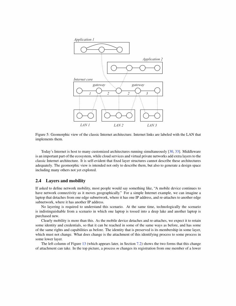
6.4 EncapsulationLike Table 1, Table 4 compares the standards on the basis of how they encapsulate overlay messages as theytravel through an underlay. Note that there are two versions of the Mobile IPv6 standard which differ in thisrespect (the newer [26] supersedes the older [17], so this comparison is of academic interest only).
Protocol EncapsulationHIP encapsulation with IPSec Encapsulating Security PayloadILNPv6 none, identifier is extracted from locatorLISP Mobile Node simple encapsulationMobile IPv6 (RFC 3775) simple encapsulationMobile IPv6 (RFC 6275) Home Address destination option and Type 2 Header
Table 4: Comparison of SLM proposals on the basis of encapsulation.
Consider a message being sent from left to right in Figure 11, at a time when identifier I1 has locatorL3 and identifier I2 has locator L2. In the simplest implementation, the message consists of a messagewith source I1 and destination I2, encapsulated in a message with source L3 and destination L2. There areother possibilities, however, motivated by the desire to conserve space in message headers. This is a seriousconcern in IPv6, where each of the four address fields is 128 bits long.
LISP Mobile Node and the original version of Mobile IPv6 use simple encapsulation as above. HIP doesalso, with the additional proviso that the message body containing the identifiers is protected with IPsec. InILNP each identifier is a suffix of its current locator, so it need not be sent separately.
In the revised Mobile IPv6 standard, there is an optimization apparently based on the observation that,most of the time, only one of the endpoints of a session will be mobile. For a stationary node, the identifierand locator are always the same, and need not be sent twice. So a message from the mobile node needs asource identifier and not a destination identifier, and a message to a mobile node needs a destination identifierand not a source identifier.
Now let us assume that I1 is mobile and I2 is stationary. For messages from I2 to I1, a destinationidentifier is needed. The revised Mobile IPv6 standard uses a special Type 2 header. This is a kind of“source routing” header, allowing the source to provide a list of destination addresses through which themessage must be routed. The messages have destination list (L3; I1), where the second hop from L3 to I1is internal to the mobile host. For messages from I1 to I2, a source identifier is needed. The extra sourceaddress I1 is inserted using a special “Home Address destination option.” This option is an extension to IPv6allowing an extra field in a message header. In this way, the extra identifiers can be added to messages onlywhen needed.
One might speculate that such a complex optimization would cause trouble in the form of further, cas-cading complexities, and this is indeed the case. There are elaborate rules in [26] for processing messagesso that IPsec works correctly: each message must be processed partially with I1 in the ordinary source ordestination field, and partially with I1 moved to the Type 2 header or Home Address destination option field.Note that this is an interaction that has been explicitly recognized and accommodated in the standard. Noone knows how many problematic interactions with other protocols, caused by this optimization, will bediscovered if Mobile IPv6 comes into widespread use.
The SLM implementation of Mobile IPv6 is constrained by the need to compose with the DRM im-plementation of Mobile IPv6 (see Section 7.3). If there were not so many constraints, the size of headerscould be reduced without violating the principle of separation of concerns. For example, Figure 12 revisesFigure 11 in an obvious way as suggested by the geomorphic view. The session protocol in the locator layernow performs both TCP and SLM functions.
In the identifier layer, the link between I1 and I2 is uniquely identified at one end by I1, p1, wherep1 is a port number, and uniquely identified at the other end by I2, p2. Note that the identifier layer ismore like an application layer than an IP layer in that it has no forwarding—only direct links betweenpairs of communicating endpoints. Consequently, once the link has been set up, there is absolutely no

p1 p2application/identifier
layer
locatorlayer
I1 I2
L4L2L3L1
link
linklink link
session with mobility and reliability
Figure 12: A more efficient version of Figure 11.
need to transmit I1 and I2 in data messages. Each endpoint simply uses the port number to pass messagesunambiguously across the layer boundary. Figure 12 has many similarities with TCP Migrate [32] and Serval[25, 3], which are other proposals for SLM.
7 Composition of the patterns
7.1 Structural modelingThe geomorphic view of networking is rigorously defined and can be formalized. We have formalizedvarious aspects of the geomorphic view in Alloy, which is the modeling language of the Alloy Analyzer[15], and in Promela, which is the modeling language of the Spin model checker [13]. These are structuralmodels.
Networking researchers and practitioners are accustomed to analytical models, which are also formal,but quantitative rather than structural. One can assign numbers to some symbols in an analytical model, givethe numbers and model to a suitable evaluator, and receive numbers for other symbols in the model.
Structural models are similar, except that evaluation is logical rather than quantitative. We assume thatsome formulas in a model are true, give the assumptions and the model to a suitable evaluator such as theAlloy Analyzer or Spin, and receive information about the truth of other formulas. We either learn that aformula is true, or get a counterexample showing why it is not true.
Sections 3 through 6 should have made clear why the term we use to describe these models is structural.We use them to describe hardware and software structures within networks, and to compare mechanismsbased on where their structures are similar and different. We also use them to show how structural decisionsconstrain other decisions and affect important properties such as scalability and interoperability. In the nextsubsection, we will mention some additional knowledge gained with the help of structural modeling.
7.2 Generating the design space of mobilityAn instance of mobility is an isolated episode in which one layer member changes its attachment from oneunderlay member to another. One of our goals is to give network architects the freedom to handle anyinstance of mobility with any mobility pattern at any level of the layer hierarchy. This should enhanceefficiency and scalability by allowing solutions that are finely tuned to the characteristics of the problemthey are solving.

DRM
0
1
2
3
SLM
0
1
2
DRM
0
1
2
DRM
0
1
2
SLM0
1 SLM
0
1
2
m’’
m’
m1 m2
a1 a2
m’
m1 m2
a1 a2
m’
m1 m2
a1 a2
m’
m
a1 a2
m’
m
a1 a2
m
a1 a2
Figure 13: Generating the design space of mobility.
The first step was to identify the two possible implementation patterns and to provide sufficiently abstractversions of them (Section 3). The next step, taken in this section, is to show that any instance of mobilitycan be implemented with either pattern at almost any level of the layer hierarchy.
In the left column of Figure 13, top half, we see a fundamental instance of mobility in which the oldand new locations are in the same layer at Level 0. As notated, the channel at Level 1 can be preserved bysession-location mobility (SLM) at Level 0. In the left column, bottom half, we see a fundamental instanceof mobility in which the old and new locations are in different layers at Level 0. As notated, a channel atLevel 2 can be preserved by dynamic routing mobility (DRM) at Level 1.
The middle column of the figure shows the effects of a “lifting” transformation in which each mobilityimplementation is moved up a level in the hierarchy. The purpose is to show that mobility can be imple-mented in many different places, if the current architecture allows it or the designer has control of the contentand design of relevant layers. In each case member m at Level 1 is replaced by two members m1 and m2.Neither m1 nor m2 is mobile, as each has a stationary registration in Level 0 throughout its lifetime. Nowmember m’ at Level 2 is mobile. As shown in the figure (top), a channel in Level 2 with m’ as its higherendpoint can be preserved by SLM at Level 1. Or, as shown at the bottom, a channel in Level 3 with m” asits higher endpoint and m’ as its lower endpoint can be preserved by DRM at Level 2.
The right column of the figure shows where one implementation pattern can be replaced by the other. Toreplace SLM by DRM (top right), it is necessary to lift the channel up one level. To replace DRM by SLM(bottom right), the channel can stay at the same level, but the mobility must be lifted up a level.
Figure 13 illustrates the crucial point that mobility is about name spaces and member identities in indi-vidual layers, and about the mappings between these concepts in adjacent layers. Identity is a fluid conceptin software systems, which is why mobility is fluid, and can be pushed around an architecture to appear indifferent places.
If mobility is fluid, and different implementations are used for different purposes at different levels ofan architecture, it follows that any layer could include implementations of either or both mobility patterns.Is this a problem? We have proved that it is not, at least for implementations of the patterns as modeledin Alloy. Verification with the Alloy Analyzer shows that the two patterns can be freely composed, in the

Internet corewith
Mobile IPv6
tunnelinglayer
C
C
HA
HA
M
CO1CO2
MM
MM
C C
CC
CO2CO2
HA
HA
Figure 14: The paths of messages to and from mobile host M with the dynamic-routing mobility mechanismof Mobile IPv6. Special links are drawn with heavier lines. Only the links employed in the path are shown.
same layer or different layers of the same hierarchy. They will work together without interference or otherundesirable interactions [38].
The limitation of this theoretical result is that, to benefit from proven compositionality, implementationsmust maintain the minimal separation of concerns inherent in our model of the geomorphic view. If realimplementations have state dependencies or interfering actions that are not represented in our model, they arenot necessarily compositional even if the theorem says they are. In effect the model is presenting sufficientconditions for compositionality, which can be used as design guidelines for real systems.
7.3 Composition in Mobile IPv6As we saw in Section 5, Mobile IPv4 is an instance of DRM. Mobile IPv6 [17, 26] uses a similar DRMmechanism, and also composes it with the SLM mechanism described in Section 6. We first consider theDRM mechanism.
Figure 14 is the Mobile IPv6 version of Figure 10. Note that Mobile IPv6 has no foreign agents, as theirfunctions are performed by the mobile hosts themselves. In the figure, both the old attachment of M at CO1and its new attachment at CO2 are shown. Normal routers are not shown, being replaced by ellipses in thepaths consisting of normal links.
Figure 14 also differs from Figure 10 in showing the source and destination addresses of the messageson every link (source on top, destination below). Thus a message in the core layer with source C anddestination M is forwarded on a special link from HA to M. The implementation of this special link in thetunneling layer encapsulates the message in another message with source HA and destination CO2, and sendsit through normal IP links and routers.
Figure 14 also differs from Figure 10 in showing the paths of return messages from M to C. In contrast toMIPv4, return messages from M travel on a special link as far as HA. At HA they enter the realm of normallinks and routers. There is no problem with ingress filtering because M belongs to the address block of HA’ssubnetwork, so M is a normal source address at that location.
The big problem with Mobile IP is the path cost of routing every message through a mobile host’s homeagent. Path cost is even worse in Mobile IPv6 than in Mobile IPv4, because it is incurred by messages from

Internet corewith
Mobile IPv6
tunnelinglayer
C
C
M
CO1CO2CO2CO2
MM
C
C
C
C
Figure 15: The paths of messages to and from mobile host M with the session-location mobility mechanismof Mobile IPv6. Special links are drawn with heavier lines.
a mobile host as well as messages to it. To reduce this problem, Mobile IPv6 standardizes a version of SLMcalled “route optimization,” as already presented in Section 6. SLM is used only after the session betweenC and M is established, and only if both endpoints have the protocol capability.
Figure 15 shows the SLM mechanism of Mobile IPv6 in the same context as its DRM mechanismin Figure 14. For simplicity, this figure uses simple encapsulation as in [17]. After the endpoints haveexchanged messages to set up SLM, they send messages on special links implemented in the tunnelinglayer. Note that these are different special links than those used by DRM (Figure 14). The DRM speciallinks involve HA and will change when M moves. The SLM special links do not involve HA, and will notchange from the perspective of the core layer when M moves. With SLM, the only role played by HA in thetunneling layer is to store the directory entry for M. It is not needed originally because when SLM beginsthe two endpoints are already connected and know each other’s locations in the tunneling layer, but it maybe needed in case of simultaneous handoff.
Figure 15 also shows the SLM mechanism of Mobile IPv6 in the same context as Figure 11. The “Internetcore with Mobile IPv6” layer in Figure 15 is the same as the identifier layer in Figure 11. The tunnelinglayer in Figure 15 is the same as the locator layer in Figure 11.
So far our discussion of the Internet core/identifier layer has been limited to its links. We have seenthat C and M may have a choice of links over which to send their messages. Because the network pathassociated with each link is different, its performance may be different. It is the job of TCP in the Internetcore/identifier layer to smooth over any difficulties caused by diverse paths, for example by ensuring thatmessages are delivered to an application layer in FIFO order.
The design space generated in Section 7.2 is intended primarily for compositions in which differentinstances of mobility are managed by different mechanisms or at different levels of the architecture. Com-position in Mobile IPv6 is a little different because the exact same instance of mobility—pictured in thefigures as M’s change of attachment from CO1 to CO2—is being handled simultaneously by both forms ofmobility. The DRM implementation is in the core/identifier layer, while the SLM implementation is in thetunneling/locator layer. DRM is the default mechanism, because SLM can only be used if both endpointsare SLM-enabled.
8 Design considerations related to mobilityMobility mechanisms lie close to the heart of networking, so they are related to many other communicationservices and aspects of networking. In this section, we touch briefly on several other topics closely relatedto mobility.
8.1 MultihomingIncreasingly, mobile devices connect to the Internet via multiple interfaces (e.g., a laptop with WiFi andwired Ethernet interfaces, a smartphone with WiFi and cellular interfaces, or a virtual machine running on aphysical server with multiple wired Ethernet interfaces). Since these interfaces usually connect to differentadministrative domains (e.g., a campus WiFi network and a commercial cellular provider), they must havedifferent IP addresses in different address blocks. There is no name for the Internet host itself, and no wayto route to the host itself rather than a specific one of its interfaces.
Sequential multihoming is the use by a host of multiple interfaces, one after the other, during the lifetimeof a channel. A mobility mechanism can be used to implement sequential multihoming; in principle eitherof the mobility patterns can be used to provide it.
If we look at the specific real mobility protocols in Sections 4 through 6, however, we see that the DRMprotocols in Sections 4 and 5 work with a single IP address per host, while the SLM protocols in Section 6work with multiple IP addresses per host. This is an artifact of where these protocols sit in the IP stack ratherthan an inherent property of the implementation patterns, but it does mean that these SLM implementationsare currently a better match for multihoming than these DRM implementations.
Simultaneous multihoming allows a host to use its multiple interfaces to contribute bandwidth to thesame channel simultaneously. Simultaneous multihoming is closely related to sequential multihoming andtherefore to mobility, but not strictly the same because the multiple interfaces of a host might not be allowedto change during the lifetime of a channel. Of course, what we really want is simultaneous and sequentialmultihoming, which is a little more complex than sequential multihoming because it requires protocol ex-tensions so that a layer member can have and use more than one attachment at a time. All of HIP, ILNP,LISP Mobile Node, and Serval already have session protocols capable of simultaneous multihoming.
Because there is such a close association between host multihoming and mobility, the well-known mul-tihoming protocols Multipath TCP [9] and the Stream Control Transmission Protocol (SCTP) [34] are worthstudying. They have been used enough to gather experience on the performance aspects of switching fromone interface to another, and on how performance affects the buffering and rate control in real transport(session) protocols such as TCP. This experience is as relevant to mobility as it is to multihoming.
8.2 AnycastIncreasingly, the Internet is a platform for users to access services hosted on multiple servers in multiplelocations. The appropriate network abstraction for their requirements is anycast, in which a service has ananycast name that corresponds to a group of servers offering the service. A request for a communicationchannel to the service can result in a channel to any member of the group of servers.
For simple query-response services like DNS, all server replicas can share a single locator (i.e., an IPaddress), and rely on IP routing to direct client requests to one of the server replicas. However, IP routingdoes not guarantee that multiple messages sent to the same IP address would reach the same server replica.In today’s Internet, a domain name for a geo-replicated service can map to multiple IP addresses, one foreach server replica. This supports communication services with multiple message exchanges between client

and server. It is different from mobility, however, because the higher-level domain name has nothing to dowith the channel after the initial DNS lookup.
Alternatively, anycast could be combined with SLM, as it is in Serval [25, 3]. A Serval identifier is ananycast name, and is registered as located at a dynamic group of servers in the locator layer. When a requestfor a channel to an identifier is handled by the Serval session protocol, the protocol selects the locator ofsome member of the group. In contrast to the previous paragraph, the identifier remains the name of thechannel’s higher endpoint throughout its lifetime. The SLM session protocol can thus maintain the channelthrough both mobility events and changes to the membership of the server group.
8.3 Subnetwork mobilityMobility proposals typically focus on the movement of a single mobile endpoint, like a mobile device or avirtual machine. However, in some scenarios a subnetwork serving multiple endpoints can move from onelocation to another. For example, a fast-moving bus, train, or plane may carry a LAN that provides networkconnectivity to a large collection of passengers.
Dynamic-routing mobility in a hierarchical layer naturally handles subnetwork mobility by updating theroutes used to reach the entire aggregated block of names. For example, Boeing had an early in-flight WiFiservice that provided seamless mobility for airline passengers by associating each international flight withan IP address block, and announcing the block into the global routing system at different locations as theplane moved [1]. However, this solution required all interdomain routers in the Internet to store and updatefine-grained routing information, leading to high overhead.
In our recent work [38], we have shown that subnetwork mobility is merely the mobility of the gateway’sattachment to the larger network, and is implemented with the same two patterns as mobility of endpoints.We identified several applications of the design patterns that seem promising for handling combinationsof subnetwork mobility and endpoint mobility. These solutions have the property that the mechanism forsubnetwork mobility (a bus moves its access point from one roadside LAN to another) is completely inde-pendent of the mechanism for endpoint mobility (a user with a laptop gets on and off the bus). Nevertheless,it is not yet clear which solutions for subnetwork mobility would be most viable in practice.
8.4 Incremental deployment and interoperationDeploying new protocols that span administrative domains is always challenging, since the Internet is afederated infrastructure and cannot easily have everyone upgrade to a new protocol at the same time. Mostreal deployments are DRM mechanisms that operate within a single administrative domain (e.g., cellularnetworks, Ethernet LANs, or data-center networks), or require support only from the mobile endpoint and asmall number of routers (e.g., Mobile IPv4).
It is not surprising that most real mobility implementations use DRM, because SLM entails many moredeployment hurdles. There can be a new set of identifiers, a new global directory service, changes to bothendpoints, and even changes to the service interface that are visible to applications. The early SLM protocolTCP Migrate [32] is probably the most deployable, requiring only changes to the operating system at theparticipating endpoints, but even so it has not had significant deployment.
Nevertheless, as noted in the introduction, the pressure for better network mobility support is mounting.Ubiquitous computing may be a particularly powerful motivator, because an enormous number of sensorsand actuators will require network access. This could accelerate the adoption of IPv6, enabling many otherchanges in its wake.

For incremental deployment, an SLM-enabled host can interoperate with a legacy host in a degradedmode in which mobility does not work but other functions do. For full mobility, an SLM-enabled hostcan interoperate with a legacy host through a proxy or other middlebox. This raises many new questionsconcerning how a middlebox is introduced into the path between the hosts, and on the scalability of statefulmiddleboxes. These new questions must be added to the perennial list of old interoperability questions, suchas how to traverse NAT boxes. Identifying effective ways to deploy these protocols incrementally remainsan active area of research and standards work.
8.5 SecurityAll mobility solutions raise important questions about security. In DRM, who is authorized to announce rout-ing changes for an address or address block? In SLM, who is authorized to update the directory service anda mobile endpoint’s correspondents? Answering these questions successfully requires unforgeable notionsof identity, and secure protocols for sending update messages to routers, directory servers, and endpoints.Can accidental misconfigurations or malicious attacks overload the routers, directory servers, or endpoints?Preventing denial-of-service attacks requires effective ways to limit the work performed before recognizingthat messages are unauthorized.
As mentioned in Section 3.3, some people believe that SLM protocols face greater security challengesbecause arbitrary endpoints can initiate updates to global layer state. On the other hand, SLM protocols pro-vide for persistent identifiers which can be used as the basis for authentication of hosts, a valuable assistanceto security. SLM protocols that use DNS as the directory service can update DNS records with an existingsecure protocol [37]. Some protocols, like HIP and Serval, embed an endpoint’s public key (or a hash of thekey) in the identifier; these identifiers support secure communication as well as authentication. Still, securityis a rich and important topic warranting a much deeper treatment, especially since new protocols can easilyintroduce unforeseen vulnerabilities and new threats.
9 ConclusionIn this chapter we have presented an abstract framework for describing, understanding, and comparing ap-proaches to network mobility. As illustrations, we have covered several mobility protocols in some detail.We believe the geomorphic model provides a clear and precise way to understand the considerable simi-larities between different mobility proposals, allowing discussions to focus on their meaningful distinctionsrather than artificial differences in terminology.
We have compared mobility proposals on both qualitative (deployment constraints, security) and quanti-tative (resource costs, latency) criteria. The basis for making comparisons has been completely structural, inthe sense of structural modeling as defined in Section 7.1. This is important because structural comparisonsare vastly easier to obtain than comparisons based on simulation, and should always be the first step in anyevaluation project.
In the interest of brevity, our discussions of quantitative criteria have merely suggested trends and trade-offs, rather than providing a more substantive analysis. A true understanding of metrics such as storage cost,update cost, and path cost requires a more detailed characterization of the proposals, including supportingtechnologies such as routing protocols and directory services. Scalability depends on how these costs growas the size of a network grows within the expected range.
Equally important, different mobility mechanisms can be composed. Even today it would not be surpris-ing to see dynamic-routing mobility used within an administrative domain, while session-location mobility isused simultaneously across administrative boundaries. The ultimate goal would be to compose performance

models along with the mechanisms they are modeling, so that the performance of a composed solution couldbe derived from the performance of its components.
Today, many Internet applications that could benefit from mobility use work-arounds instead, satisfyingthe need for session continuity with ad hoc application-specific mechanisms, or simply doing without [12].This is both an effect and a cause of scant deployment of mobility mechanisms. Most existing mobilityprotocols operate at fairly low levels in a network architecture, specifically the link, network, and transportlevels of the classic Internet stack. At these levels they are expensive, difficult to deploy, or both.
Many of these limitations are unnecessary, as the essence of mobility is simply a dynamic binding ofmore abstract names to more concrete names. As such, mobility can be easily implemented in middlewareas a service to even higher-level application layers. We believe that this is a fruitful avenue for further explo-ration, particularly because it might be easier to optimize narrowly-targeted implementations of mobility.
More generally, we believe that the geomorphic view promotes common terminology, modularity, sepa-ration of concerns, discovery of design patterns, composition, rigorous reasoning, and code reuse in network-ing. While widely appreciated by software engineers, these concepts have been less central to the study ofnetworking. We believe that the geomorphic view should be extended to understand other important aspectsof networking. We also believe that an appreciation of these concepts would be valuable for networkingresearchers and practitioners alike, far beyond the treatment of any one subject like network mobility.
References[1] ABARBANEL, B. Implementing global network mobility using BGP. NANOG Pre-
sentation, http://www.nanog.org/meetings/nanog31/abstracts.php?pt=NTk1Jm5hbm9nMzE=&nm=nanog31, May 2004.
[2] AKYILDIZ, I. F., XIE, J., AND MOHANTY, S. A survey of mobility management in next-generationall-IP-based wireless systems. IEEE Wireless Communications 11, 4 (August 2004), 16–28.
[3] ARYE, M., NORDSTROM, E., KIEFER, R., REXFORD, J., AND FREEDMAN, M. J. A formally-verified migration protocol for mobile, multi-homed hosts. In Proceedings of the International Con-ference on Network Protocols (October/November 2012).
[4] ATKINSON, R., BHATTI, S., AND HAILES, S. ILNP: Mobility, multi-homing, localised addressingand security through naming. Telecommunication Systems 42, 3-4 (December 2009), 273–291.
[5] ATKINSON, R., BHATTI, S., AND HAILES, S. Evolving the Internet architecture through naming.IEEE Journal on Selected Areas in Communication 28, 8 (October 2010), 1319–1325.
[6] CLARK, D. The design philosophy of the DARPA internet protocols. In Symposium proceedings onCommunications architectures and protocols (New York, NY, USA, 1988), SIGCOMM ’88, ACM,pp. 106–114.
[7] DAY, J. Patterns in Network Architecture: A Return to Fundamentals. Prentice Hall, 2008.
[8] FARINACCI, D., FULLER, V., MEYER, D., AND LEWIS, D. The locator/ID separation protocol(LISP). IETF Request for Comments 6830, January 2013.
[9] FORD, A., RAICIU, C., HANDLEY, M., AND BONAVENTURE, O. TCP extensions for multipathoperation with multiple addresses. IETF Request For Comments 6824, January 2013.
[10] GREENBERG, A., HAMILTON, J. R., JAIN, N., KANDULA, S., KIM, C., LAHIRI, P., MALTZ, D. A.,PATEL, P., AND SENGUPTA, S. VL2: a scalable and flexible data center network. In Proceedings of theACM SIGCOMM 2009 conference on Data communication (New York, NY, USA, 2009), SIGCOMM’09, ACM, pp. 51–62.
[11] GUPTA, A., LISKOV, B., AND RODRIGUES, R. One hop lookups for peer-to-peer overlays. In HotOS(Lihue, HI, May 2003).
[12] HANDLEY, M. Why the Internet only just works. BT Technology Journal 24, 3 (July 2006), 119–129.
[13] HOLZMANN, G. J. The Spin Model Checker: Primer and Reference Manual. Addison-Wesley, 2004.
[14] ITU. Information Technology—Open Systems Interconnection—Basic Reference Model: The basicmodel. ITU-T Recommendation X.200, 1994.
[15] JACKSON, D. Software Abstractions: Logic, Language, and Analysis. MIT Press, 2006, 2012.
[16] JALAPARTI, V., CAESAR, M., LEE, S., PANG, J., AND VAN DER MERWE, K. SMOG: A cloud plat-form for seamless wide area migration of networked games. In Proceedings of ACM/IEEE NetGames(November 2012).
[17] JOHNSON, D., PERKINS, C., AND ARKKO, J. Mobility support in IPv6. IETF Request for Comments3775, June 2004.
[18] KIM, C., CAESAR, M., AND REXFORD, J. Floodless in SEATTLE: A scalable Ethernet architecturefor large enterprises. In Proceedings of ACM SIGCOMM (2008).
[19] MOSKOVITZ, R., AND NIKANDER, P. Host identity protocol HIP architecture. IETF Network Work-ing Group Request for Comments 4423, 2006.
[20] MYSORE, J., AND BHARGHAVAN, V. A new multicasting-based architecture for Internet host mobil-ity. In Proceedings of the 3rd Annual ACM/IEEE International conference on Mobile Computing andNetworking (1997).
[21] MYSORE, R. N., PAMBORIS, A., FARRINGTON, N., HUANG, N., MIRI, P., RADHAKRISHNAN, S.,SUBRAMANYA, V., AND VAHDAT, A. PortLand: A scalable fault-tolerant layer 2 data center networkfabric. In Proceedings of ACM SIGCOMM (August 2009).
[22] NATAL, A. R., JAKAB, L., PORTOLES, M., ERMAGAN, V., NATARAJAN, P., MAINO, F., MEYER,D., AND APARICIO, A. C. LISP-MN: Mobile networking through LISP. Wireless Personal Commu-nications 70, 1 (May 2013), 253–266.
[23] NICIRA. It’s time to virtualize the network. http://nicira.com/en/network-virtualization-platform, 2012.
[24] NIKANDER, P., GURTOV, A., AND HENDERSON, T. R. Host identity protocol (HIP): Connectivity,mobility, multi-homing, security, and privacy over IPv4 and IPv6 networks. IEEE CommunicationsSurveys and Tutorials 12, 2 (April 2010), 186–204.
[25] NORDSTROM, E., SHUE, D., GOPALAN, P., KIEFER, R., ARYE, M., KO, S., REXFORD, J., ANDFREEDMAN, M. J. Serval: An end-host stack for service-centric networking. In Proceedings of the9th Symposium on Networked Systems Design and Implementation (April 2012).

[26] PERKINS, C., JOHNSON, D., AND ARKKO, J. Mobility support in IPv6. IETF Request for Comments6275, July 2011.
[27] PERKINS, C. E. Mobile IP. IEEE Communications (May 1997).
[28] PERKINS, C. E. IP mobility support for IPv4. IETF Network Working Group Request for Comments3344, 2002.
[29] PERLMAN, R. Rbridges: Transparent routing. In Proceedings of IEEE INFOCOM (2004).
[30] ROSCOE, T. The end of Internet architecture. In Proceedings of the 5th Workshop on Hot Topics inNetworks (2006).
[31] SCHULZRINNE, H., AND WEDLUND, E. Application-layer mobility using SIP. Mobile Computingand Communications Review 4, 3 (July 2000), 47–57.
[32] SNOEREN, A. C., AND BALAKRISHNAN, H. An end-to-end approach to host mobility. In Proceedingsof MOBICOM (2000).
[33] SPATSCHECK, O. Layers of success. IEEE Internet Computing 17, 1 (2013), 3–6.
[34] STEWART, R. Stream Control Transmission Protocol. IETF Network Working Group Request forComments 4960, September 2007.
[35] STOICA, I., ADKINS, D., ZHUANG, S., SHENKER, S., AND SURANA, S. Internet indirection infras-tructure. In Proceedings of ACM SIGCOMM (August 2002), ACM.
[36] TOUCH, J., AND PERLMAN, R. Transparent Interconnection of Lots of Links (TRILL): Problem andapplicability statement. IETF Request For Comments 5556, May 2009.
[37] WELLINGTON, B. Secure domain name system (DNS) dynamic update. IETF Network WorkingGroup Request for Comments 3007, November 2000.
[38] ZAVE, P., AND REXFORD, J. Compositional network mobility. In Proceedings of the 5th Work-ing Conference on Verified Software: Theories, Tools, and Experiments (May 2013), Springer-VerlagLNCS to appear.
[39] ZHU, Z., WAKIKAWA, R., AND ZHANG, L. A survey of mobility support in the Internet. IETFRequest for Comments 6301, July 2011.


![Association between cognitive function and life-space mobility in … · 2018. 9. 24. · Life-space mobility (LSA) The Life-Space Assessment index [1] was used to investigate life-space](https://static.fdocuments.us/doc/165x107/613ba50bf8f21c0c82691cf7/association-between-cognitive-function-and-life-space-mobility-in-2018-9-24.jpg)
