The Design of Ventilated Improved Pit Latrines · the design of ventilated improved pit (VIP)...
84
~a1 Note No. 13 321.4 84 DE )flS Development Programme 1 Project INT/81/047 gency: World Bank The Design of Ventilated Improved Pit Latrines by D. Duncan Mara, Technology Advisory Group (TAG) UNITED NATIONS 99* 990 A joint United Nations Development Programme and World Bank Contribution to the International Drinking Water Supply and Sanitation Decade 321.4—1989
Transcript of The Design of Ventilated Improved Pit Latrines · the design of ventilated improved pit (VIP)...

~a1NoteNo. 13321.4
84 DE)flS DevelopmentProgramme1 ProjectINT/81/047gency:World Bank
The Designof VentilatedImproved Pit Latrines
by D. DuncanMara,TechnologyAdvisory Group(TAG)
UNITED NATIONS 99* 990
A joint UnitedNationsDevelopmentProgrammeandWorldBankContributionto theInternationalDrinking WaterSupplyandSanitationDecade 321.4—1989
Copyright © 1984The International Bank for Reconstruction and Development/THE WORLDBANK1818 H Street, NWWashington, DC 20433, USA.
All rights reservedManufactured in the United States of America
(1)
PREFACE
This Technical Note by D. Duncan Mara develops a general ap~roach to
the design of ventilated improved pit (VIP) latrines, based on TAG’s’ recentexperience in Botswana, Brazil, Ghana, Kenya, Lesotho, Tanzania andZimbabwe. Further details of country—specific deslgns (currently forBotswana, Tanzania and Zimbabwe) are given in other Technical Notes in thisseries.
This paper Is one of a series of Informal Technical Notes prepared byTAG on varlous aspects of water supply and sanltation programs in developingcountries. The initial emphasis of TAG was on the promotion of policy shIftsfrom KIgh—cost to low—cost on—site sanitation technologies. This emphasis Isnow being progressively directed to a focus on institutional development foron—site low—cost sanitation program delivery.
This note was origlnally prepared as an Internal discusslondocument. Its wide distribution does not Imply endorsement by the sectoragencIes, government, or donor agencies concerned with programs, nor by theWorld Bank or the United Nations Development Programme.
TAG is interested in recelving comments and suggestions on the paper,and, In particular, information on costs of technology, delivery and supportsystems, and generally, Information on experience in program Implementation.All communication should be addressed to the Project Manager, UNDP ProjectINT/81/047, Water Supply and Urban Development Department, The World Bank,1818 H. Street, NW. Washington, DC 20433.
Richard N. MiddietonProject Manager
*1 TAG: Technology Advlsory Group established under the United NationsDevelopment Programme Global Project GLO/78/006 (renumbered on January 1,1982; now UNDP Interregional Project INT/81/047: ~Development andImplementation of Low—cost Sanitation Investment Projects”), executed bythe World Bank.
i1sr’)2x9~

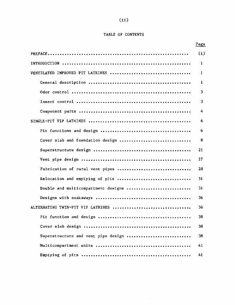
(ii)
TABLE OF CONTENTS
Page
PREFACE . Ci)
INTRODUCTION . .. 1
VENTILATEDIMPROVEDPITLATRINES . 1
General description . . . . . . . . . . . . . . . 1
Odor control ........... . 3
Insect control .............. 3
Component parts . . . . . . . . . . . . . . . . . . . . . . . . . . . . . . . . . . . . 4
SINGLE—PIT VIP LATRINES 6
Pit functions and design . 6
Cover slab and foundation design 8
S uperstructure design . . . . . . . . . . . . . . . . . . . . . . . . . . . . . . . . . . . . . . . . . 21
Vent pipe design . . . . . . . . . . . . . . . . . . . . . . . . . . . . . . . . . . . . . . . . . . . . . . 27
Fabricationofruralventpipes ............................... 28
Relocationandemptyingof pits .................... . 31
Double and multicompartment designs 31
Designs with soakaways 36
ALTERNATINGTWIN—PITVIPLATRINES . 36
Pit functionand design 38
Cover slab design . . . . . . . . . . . . . . . . . . . . . . . . . . . . . . . . . . . . . . 38
Superstructure and vent pipe design .......... ............ 38
Multicompartnient units 41
Eniptying of pits . .. . 41

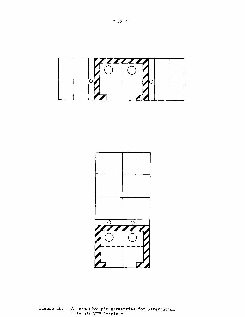
(iii)
APPLICABILITY AND CONSTRAINTS . . 43
Rousing density . . . . . . 43
Water suppiy service level . . . . . . . . . . . . 43
Ground conditlons .. . 43
Groundwater pollution 43
S ociocuitural factors . 44
DESIGN SELECTION CRITERIA . . . . . . . . . 46
Favourabie ground conditions . 46
Adverse ground conditions . . . . . . . . . . . . . . . 49
Design exauiples . . 49
COSTS .............• .. ................. 51
ANNEXES:
1. Soli stability criteria . . . . . . . 55
II. Case studies .... . 56
A • Zimbabwe 56
B • Botswana . ....... 60
C • Tanzania ................... •...... . 63
D . Ghana 63
E . Brazil •.. ............................. 66
III. Cost of Alternative Components for Rural Brick VIP
L atrines In Zimbabwe . . . 69
INTRODUCTION
1. Excreta—related diseases are responsible for a large proportionof the morbidity and mortality in developing countries, especially amongstlow—Income communities in urban fringe and rural areas, where adequate watersuppiles and sanitation faclilties are typically absent. Excreta control isthus of paramount importance 1f the incidence of thes~,diseases is to bereduced. Recent research sponsored by the World Bank—’ has clearly shown thatexcreta—related diseases can be greatly reduced by:
(a) the provisions of sanitary toilets, of whatever type, whichpeople of all ages will use and keep clean;
(b) the effective treatinent of excreta or sewage prior to dischargeor reuse;
(c) the provlsion of an adequate water supply so that waterconsumption is In the region of 30 to 50 liters per capita perday, which is normally the minimum requirement for the controlof those excreta—related infections which have a water—washedmode of transmission; and
Cd) an effective and sustained program of personal hygiene educationby the responsible local authority.
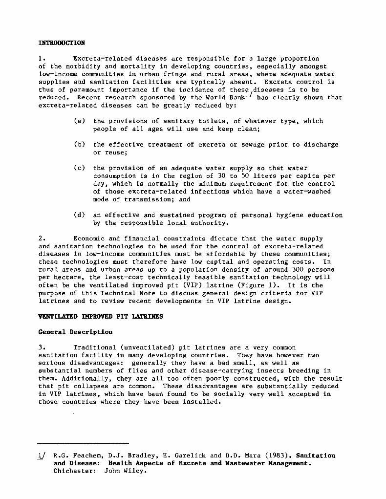
2. Economic and financial constraints dictate that the water supplyand sanitation technologies to be used for the control of excreta—relateddiseases in low—income communities must be affordabie by these communitles;these technologies must therefore have low capital and operating costs. Inrural areas and urban areas up to a population density of around 300 personsper hectare, the least—cost technically feasible sanitation technology willoften be the ventllated improved pit (VIP) latrine (Figure 1). It is thepurpose of this Technical Note to dlscuss general design criteria for VIPlatrines and to review recent developinents in VIP latrine design.
VENTILATRD DIPROVED PIT LATRINES
General Description
3. Traditional (unventilated) pit latrines are a very commonsanitation facility in many developing countries. They have however twoserious disadvantages: generally they have a bad smeli, as well assubstantial numbers of flies and other disease—carrying insects breeding Inthem. Additionally, they are all too often poorly constructed, with the resultthat pit collapses are common. These disadvantages are substantially reducedin VIP latrines, which have been found to be socially very well accepted inthose countries where they have been instailed.
!/ R.G. Feachem, D.J. Bradley, H. Garelick and D.D. Mara (1983). Sanitationand Disease: Health Aspect8 of Excreta and Wastevater Managei~nt.Chichester: John Wiley.
—2—
odors ~ flies
flyscreen
‘-t..
t..
aircurrents
pitlined
cement‘mortar
thatchroof
pvcventpipe
brickspiralsuperstructure
1.. — . .
Figure 1. Schematic diagram of a ventilated improved pit latrine.
—3—
4. A VIP iatrine differs from a traditional pit iatrine in that Ithas a taii verticai vent pipe which has a fiyscreen fitted at its top. Thevent pipe is responsibie for both odor and fiy control, as expiained inparagraphs 6 and 7 beiow•
5. There are two basic types of VIP iatrine: the single—pit iatrineand one with two pits, known as the alternating VIP latrine. The latter(described in paragraphs 45—52) is designed for the removai of the pitcontents at regular intervais of two to three years; it is a permanentsanitation facility which is especiaily suitable for use in medium densityurban areas.
Odor control
6. Fieldwork recently done in Botswana and ZimbabweL~’ has shownthat the principal mechanisminducing ventilation in VIP latrines is theaction of the wind biowing across the top of the vent pipe. The windeffectively sucks air out of the vent pipe and this air is replaced from theatmosphere via the latrine superstructure and squat—hole. Consequently thereis a strong circulation of air from outside the latrine, through thesuperstructure and squat—hoie, and up and Out of the vent pipe. Thus, anyodors emanating from the fecal material in the pit are exhausted via the ventpipe, and not via çhe squat—hole into the superstructure which, as a result,remains odor—f ree-1’. 1f the superstructure openings Cdoorways, etc.) faceinto the prevailing wind, the resuiting increased air pressure within thesuperstructure increases the fiow of air up the vent pipe and thus also helpsto control odors in the latrine; the iatrine should therefore be designed 80
that any openings face into the prevailing wind. Recommended vent pipedimensions are discussed in paragraphs 27—38.
Insect control
7. Flies. The vent pipe controls flies in VIP latrines in twoways. Firstly, since flies are attracted to pit iatrines by the fecal odorscoming from them, almost all files will try to enter the pit via the top ofthe vent pipe as that is the point from which the odors emerge; but they areprevented from entering by the flyscreen. Secondly, aithough a few flies mayenter the pit via the superstructure and squat—hole and lay their eggs in the
2/ B.A. Ryan and D.D. Mara, Pit Latrine Ventilation: Field InvestigationMethodology, TAG Technical Note No. 4; and Ventilated [aproved PitLatrines: Vent Pipe Design Guidelines, TAG Technical Note No. 6.
3/ An earlier expianation for the cause of ventilation was that the vent pipeabsorbed heat from the sun and transferred some of this energy to the airinside the vent pipe, which consequentiy became less dense than theoutside air immediately above it; it therefore rose Out of the vent pipeand was replaced by air below, 50 establishing the air circulation patterndescribed above. The fieldwork done in Botswana and Zimbabwe showed thatthe shearing action of the wind and its direction relative to any openings(doorways, etc.) in the superstructure were much more important than theabsorption of solar energy, except under very low wind conditions (seeparagraphs 26 — 38).
—4—
pit, the newly—emergent adult flies eventually resulting from these eggs flyinstinctively in the direction of the brightest light; provided that thesuperstructure is reasonably well shaded, the brightest light seen by theflies is that at the top of the vent pipe: the flies thus fly up the ventpipe but their escape is prevented by the flyscreens. Fly control is veryeffective: in a 78—day monitoring period in Zimbabwe, only 146 flies werecaught escaping from a VIP latrine, whereas 13~~~3were caught from anunvented, but otherwise identical, pit latrine.—
8. Thus the screened vent pipe has three important roles in thesuccessful performance of VIP latrines:
Ca) it eliminates fecal odors in the superstructure;
Cb) it prevents most flies from entering the pit; and
Cc) it prevents those flies bred in the pit from escaping.
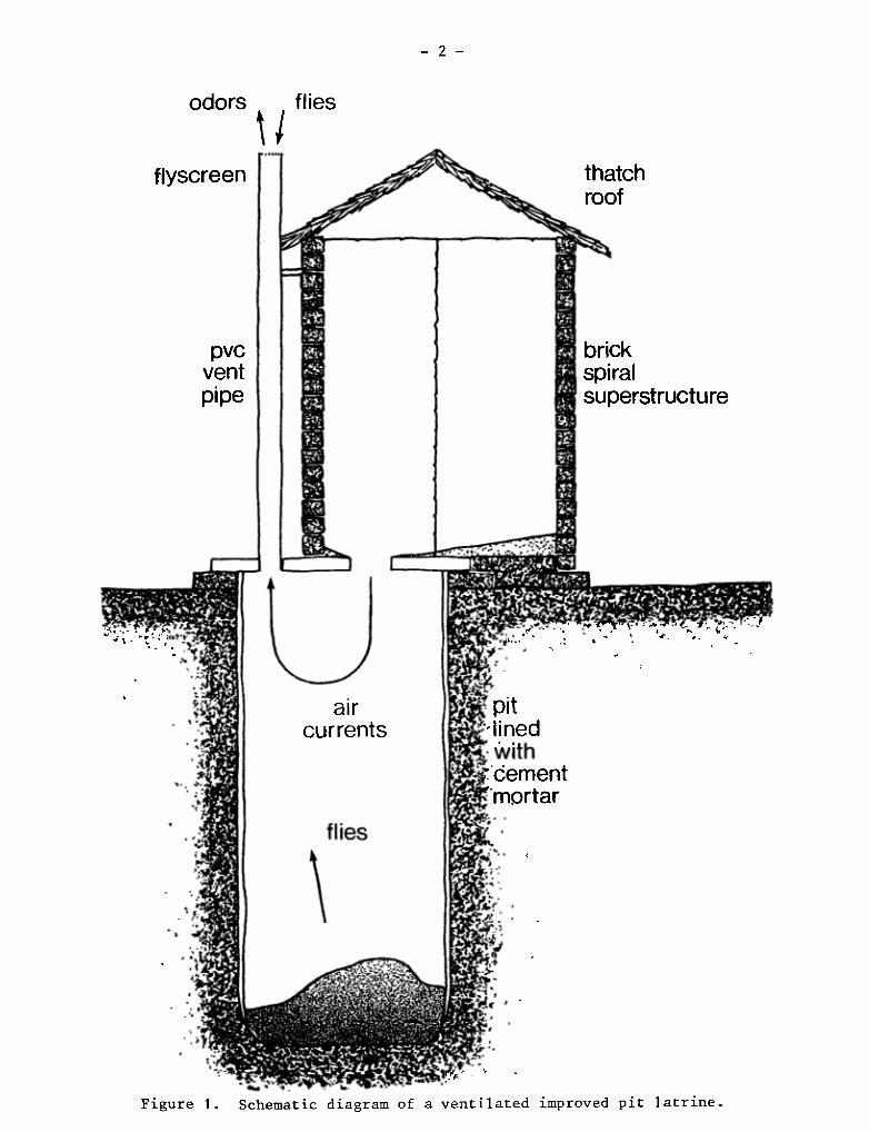
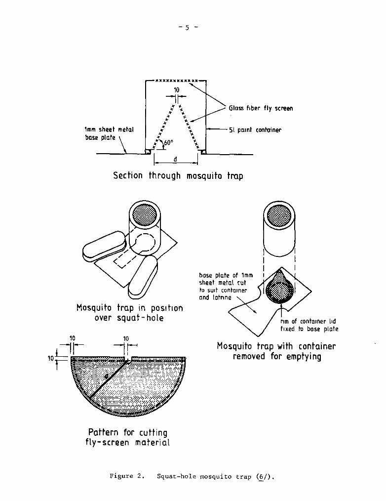
9. Mosquitoes. Culicine mosquitoes, which are the major nuisanceCbiting) mosquitoes in the urban tropics and in many countries also the vectorof Bancroftian filariasis, breed in wet pit latrines——that is, pits whichextend below the groundwater table. Newly—emergent mosquitoes are not soattracted to light as are flies, and therefore not all of them will try toescape via the vent pipe: man~,will leave via the squat—hole, even if thesuperstructure is well shaded.—’ Several substances which kill mosquitolarvae can be added to the pit; for example, kerosene, used engine oil orchemical larvicides. An alternative is to place a mosquito trap CFigure 2)over the squat—hole. This gqs been found to be very effective in field trialsin Dar es Salaam (Tanzania)—’; householders were keen to use them once theysaw how many mosquitoes were being caught in the traps and they noticed as aresult far fewer mosquitoes in their houses.
Component parts
10. Both single—pit and alternating twin—pit VIP latrines consist of thesaaie basic component parts CFigure 1: see page 2):
4/ P.R. Morgan (1976). The pit latrine — re’vived. Central Af rican Journalof Medicine, 23, 1—4.
5/ C.F. Curtis and P.M. Hawkins (1982). Rntoiwilogical Studies of On—siteSanitation Systen~in Botswana and Tanzania. Transactions of the RoyalSociety of Tropical Medicine and Hygiene, 76 Cl), 99—108.
6/ C.F. Curtis (1981). Insect Traps for Pit Latrines. Mosquito News, 40(4), 626—628.
—5—
k
k
~. _!__
1
-v
Section through mosquito trap
lof—
Mosquito trap in positionover squaf-hoLe
base plate of lmmsheet metat tutto suit containerand (atrine
rim of container lidfixed to base pLate
Mosquito trap with containerremoved for emptying
Pattern for cuttingfLy—screen material
—xxxxxx~xxx xx—
lo~
lmm sheet metalbase plate
Glass fiber fly screen
—51 paint container
d
Figure 2. Squat—hole mosquito trap (6/).
—6—
(a) the pit;(b) the cover slab and its foundatlon;Cc) the superstructure; and(d) the screened vent plpe.
There are minor design differences between the components for each type of VIPlatrlne, but the basic principles remain the same. The component parts andtheir design requlrements are first described for single—pit VIP latrines;speclfic dlfferences for alternating twin—pit latrlnes are descrlbed Inparagraphs 45—52.
SINGLE-PIT VIP LATRINES
Pit functions and design
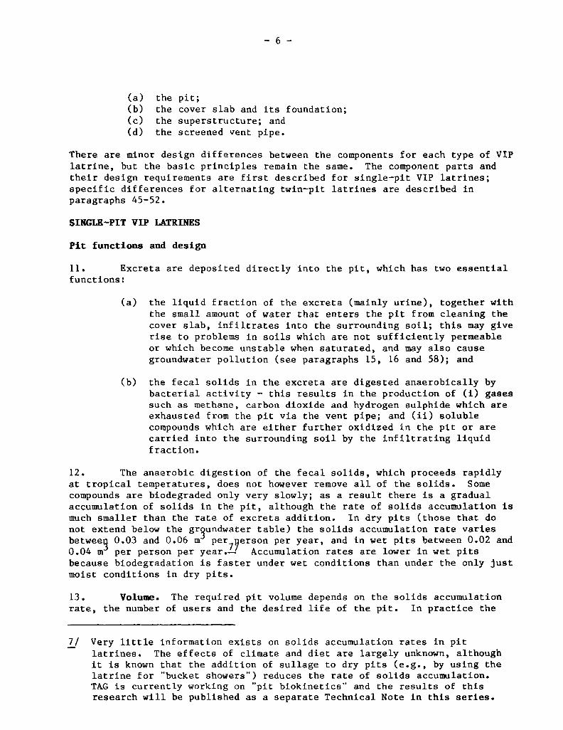
11. Excreta are deposited directly into the pit, which has two essentlal
functions:(a) the liquid fraction of the excreta (mainly urine), together with
the small amount of water that enters the pit from cleanlng thecover slab, infiltrates Into the surrounding soil; this may giverise to problems In solls whlch are not sufficlently permeableor which become unstable when saturated, and may also causegroundwater pollution (see paragraphs 15, 16 and 58); and
(b) the fecal sollds In the excreta are dlgested anaeroblcally bybacterial activity — this results In the production of CI) gasessuch as methane, carbon dioxide and hydrogen sulphide whlch areexhausted from the pit via the vent pipe; and (Ii) solublecompoundswhich are elther further oxidized In the pit or arecarried into the surrounding soil by the Infiltratlng llquidfractlon.
12. The anaeroblc digestion of the fecal solIds, which proceeds rapIdlyat tropical temperatures, does not however remove all of the solids. Somecoinpounds are biodegraded only very slowly; as a result there is a gradualaccumulatlon of solids in the pit, although the rate of solids accumulation ismuch smaller than the rate of excreta addltion. In dry pits (those that donot extend below the gr~undwatertable) the sollds accumulatlon rate varlesbetweeg 0.03 and 0.06 m per7ijerson per year, and in wet pits between 0.02 and0.04 m
3 per person per year.—’ Accumulatlon rates are lower in wet pitsbecausebiodegradation Is faster under wet conditlons than under the only justmoist conditlons in dry pits.
13. VolunE. The required pit volume depends on the sollds accumulationrate, the number of users and the desired life of the pit. In practice the
~/ Very little information exists on solids accumulation rates in pitlatrlnes. The effects of cllmate and dlet are largely unknown, althoughIt Is known that the addition of sullage to dry pIts (e.g., by using thelatrine for bucket showers”) reduces the rate of solids accumulation.TAG Is currently working on pit biokinetics’ and the results of thisresearchwill be published as a separate Technical Note In this series.
—7—
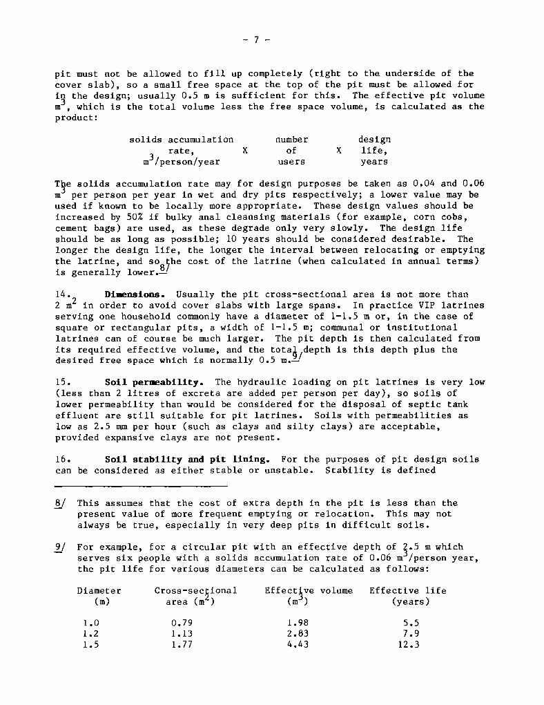
pit must not be allowed to fill up completely (right to the underside of thecover slab), 50 a small free space at the top of the pit must be allowed for
the design; usually 0.5 m is sufficient for this. The effective pit volumem , which is the total volume less the free space volume, is calculated as theproduct:
solids accumulation number designrate, X of X life,
m3/person/year users years
9e solids accumulation rate may for design purposes be taken as 0.04 and 0.06m per person per year in wet and dry pits respectively; a lower value may beused if known to be locally more appropriate. These design values should beincreased by 50% if bulky anal cleansing materials (for example, corn cobs,cement bags) are used, as these degrade only very slowly. The design lifeshould be as long as possible; 10 years should be considered desirable. Thelonger the design life, the longer the interval between relocating or emptyingthe latrine, and so çhe cost of the latrine (when calculated in annual terms)is generally lower.!~’
14. Diiwnsions. Usually the pit cross—sectional area is not more than2 m2 in order to avoid cover slabs with large spans. In practice VIP latrinesserving one household commonly have a diameter of 1—1.5 m or, in the case ofsquare or rectangular pits, a width of 1—1.5 m; communal or institutionallatrines can of course be much larger. The pit depth is then calculated fromits required effective volume, and the tota~,depth is this depth plus thedesired free space which is normally 0.5 m.—’
15. Soil per~ability. The hydraulic loading on pit latrines is very 10w(less than 2 litres of excreta are added per person per day), so soils oflower permeability than would be considered for the disposal of septic tankeffluent are still suitable for pit latrines. Soils with permeabilities aslow as 2.5 mm per hour (such as clays and silty clays) are acceptable,provided expansive clays are not present.
16. Soil stability and pit lining. For the purposes of pit design soilscan be considered as either stable or unstable. Stability is defined
8/ This assumesthat the cost of extra depth in the pit is less than thepresent value of more frequent emptying or relocation. This may notalways be true, especially in very deep pits in difficult soils.
9/ For example, for a circular pit with an effective depth of 4.5 m whichserves six people with a solids accumulation rate of 0.06 m /person year,the pit life for various diameters can be calculated as follows:
Diameter Cross—se9ional Effect~ve volume Effective life
Cm) area Cm ) Cm ) (years)
1.0 0.79 1.98 5.51.2 1.13 2.83 7.91.5 1.77 4.43 12.3
—8—
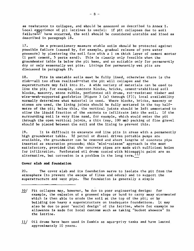
as resistance to collapse, and should be assessed as described in Annex 1.Local ejc89rience of pit latrines is useful: if pit collapses due to soilfailure—’ have occurred, the soil should be considered unstable and lined asdescribed in paragraph 18.
17. As a precautionary measure stable soils should be protected againstpossible failure (caused by, for example, gradual release of pore waterpressure) by plastering the soil face with a 1 cm thick layer of cement mortarCl part cement, 5 parts sand). This is clearly only feasible when thegroundwatertable is below the pit base, and so suitable only for permanentlydry or only seasonally wet pits. Linings for permanently wet pits arediscussedin paragraph19.
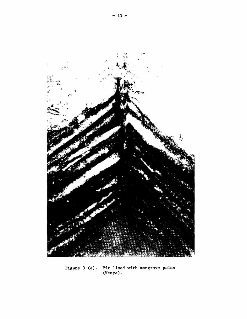
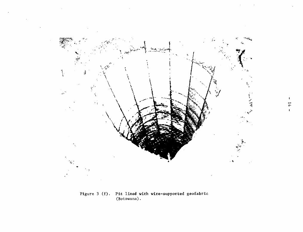
18. Pits in unstable soils must be fully lined, otherwise there is therisk——all too often realized——that the pit will collapse and thesuperstructure may fall into it. A wide variety of materials can be used toline the pit; for example, concrete blocks, bricks, cement—stabilized soilblocks, masonry, stone rubbie, perforated oil drums, rot—resistant timber andwire—mesh—supportedgeofabrics [Figure 3 Ca) through (f)]; local availabilitynormally determines what material is used. Where blocks, bricks, masonry orStones are used, the lining joints should be fully mortared in the top half—metre of the pit; below this, the vertical joints should be left unmortared toallow the liquid fraction of the excreta to infiltrate into the soil. 1f thesurrounding soil is very fine sand, for example, which would enter the pitthrough the open vertical joints, a thin (say, 100 mm) packing of fine gravelshould be placed between the soil and the lining to prevent this.
19. It is difficult to excavate and line pits in areas with a permanentlyhigh groundwater table. 1f petrol or diesel driven portable pumps areavailable, the groundwater can be removed and short lengths of concrete pipeinserted as excavation proceeds; this “mini—caisson” approach is the mostsatisfactory, provided that the concrete pipes are made with sufficient holesfor infiltration. Perforated oil drums coated with bitum~l~ic paint are analternative, but corrosion is a problem in the long term._’
Cover slab and foundation
20. The cover slab and its foundation serve to isolate the pit from theatmosphere (to prevent the escape of flies and odors) and to support thesuperstructure and vent pipe. The foundation is generally a simple
10/ Pit collapse may, however, be due to poor engineering design: forexample, the omission of a grassed slope or bund to carry away stormwaterwhich is then able to erode the soil at the top of the pit; or bybuilding too heavy a superstructure on inadequate foundations. It mayalso be due to poor “social design” of the latrine, where for example noallowance is made for local customs such as taking “bucket showers” inthe latrine.
11/ Oil drums have been used in Zambia as aqua—privy tanks and have lastedapproximately 10 years.
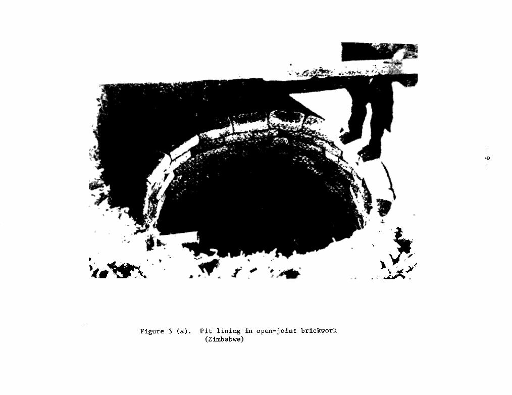
Figure 3 (a). Pit lining in open—joint brickwork(Zimbabwe)
¼0
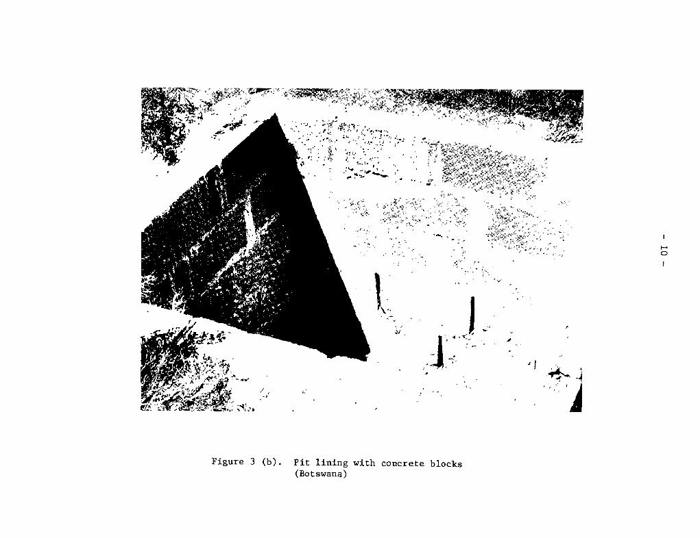
Figure 3 (b). Pit lining with concrete blocks(Botswana)
0
‘t
t
4
‘1
— 11 —
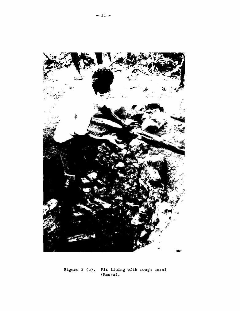
Figure 3 Cc). Pit lining with rough coral(Kenya).
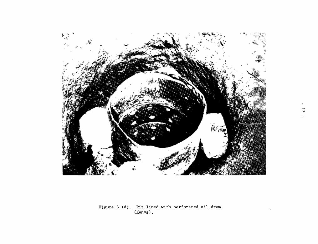
Figure 3 (d). Pit lined with perforated oil drum(Kenya).
Ni
— 13 —
t;;
Figure 3 (e). Pit lined with mangrove poles(Kenya).
~:
++
+ ~1
r. ++
T
tttttt +~
+ t%
17 +
\
t,
t
t t
1-’-is
Figure 3 (f). Pit lined with wire—supported geofabric
t t
t: t t~t~-4‘t tttt t
(Botswana).
— 15 —
ring beamof reinforced concrete or, more commonly and less expensively,bricks set in cement mortar; a single course of bricks laid on the groundsurface with their inner edge flush with the pit wall is sufficient (concretering beams are of similar dimensions). Setting the base of the foundation mi
the ground surf ace enables a gentle grass slope or cernent—stabilized soil tobe made to carry away stormwater which might otherwise erode the upper part ofthe pit wall, so endangering the structural stability of the latrine.
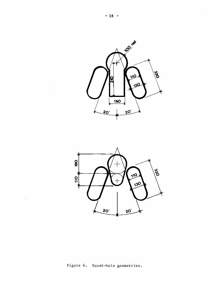
21. The cover slab must be strong enough to support the weight of thesuperstructure, vent pipe and user. It should also feel safe and should notdeflect detectably when the latrine is being used. The cover slab, whichshould be flush with the outer edge of the foundation, can be made fromreinforced concrete (Figure 4) or from rot—resistant timber (Figure 5) whichis covered with soil and then mortared. The cover slab has two holes in it:the squat—hole and one for the vent pipe. The size of the squat—hole isimportant: it should not be large enough for a child to f all through; key—shaped or pear—shaped openings (Figure 6) with a maximum width of 200 mm aregenerally used. 1f the locally preferred defecation posture is sitting,rather than squatting, a simple pedestal seat can be provided (Figure 7).
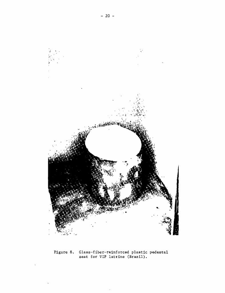
22. Where the preferred posture is squatting, it is important that thesurface of the cover slab should slope towards the scjuat—hole in order toprovide drainage for urine and the water used to clean the cover slab. Therecommended slope is 5%. Although the slab could be cast with this surfaceslope, it is usually simpler to plaster the slab to give the required slope,and also to provide a smooth finish, after the superstructure has beenbuilt. It is also worth considering whether foot—rests are to be provided;although not strictly necessary, they may be a social requirement and theyhave the advantage that, provided they are in the correct position themselves(Figure 6), they help to locate the user directly over the squat—hole and sominim+ize fouling of the cover slab with excreta. A glass—fiber reinforcedplastic cover, with integral squat—hole and foot rests, which is set in cementon the coverslab within the superstructure is shown in Figure 8.
23. It is important that the squat—hole is not kept covered when thelatrine is not in use. Squat—hole (or pedestal seat) covers interfere withthe essential circulation of air which is responsible for fly and odor control(paragraphs 6 and 7). Traditional (unventilated) pit latrines often rely 0fl
squat—hole covers to control fly breeding, but they are not only unnecessaryin the case of VIP latrines but also positively detrimental to their properoperation1 ,This is an important point to stress in user educationprograms
12/ 1f covers or seat lids are required for sociocultural or aestheticreasons, then they must be raised dear of the slab or seat so that anair space of at least 25 mm is left when the cover or lid is in the“closed” position. Further details are given in the references referredto in footnote 2.
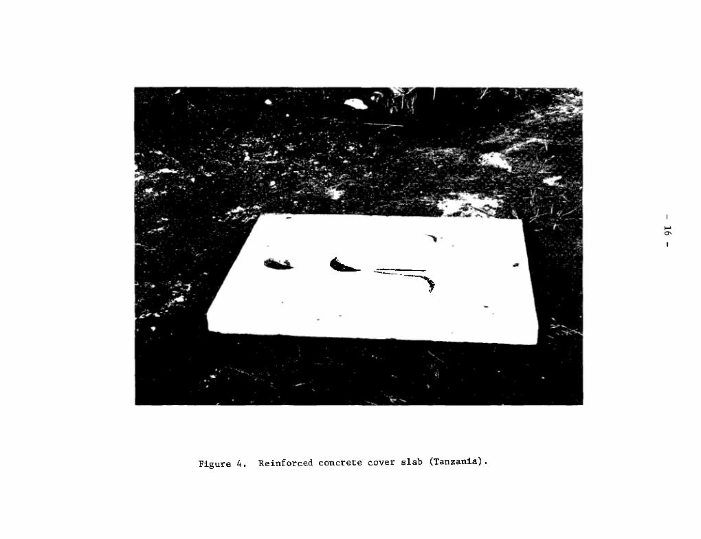
Figure 4. Reinforced concrete cover slab (Tanzania).
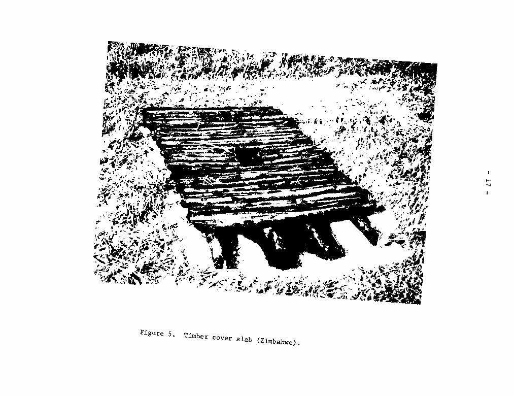
Figure 5 Timber cover slab (Zimbabwe)
—è •‘ -
— 18 —
Figure 6. Squat—hole geometries.
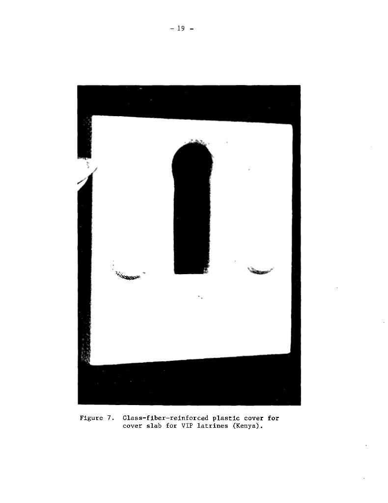
— 19 —
Glass—fiber—reinforced plastic cover forcover slab for VIP latrines (Kenya).
Figure 7.
- 20 -
ttt
~ttttt t
t t T~tt
t~
T
t tt~tt
‘t-
Figure 8. Glass—fiber—reinforced plastic pedestalseat for VIP latrine (Brazil).
— 21 —
Superstructure design
24. The function of the superstructure of any type of latrine is toprovide the user with privacy, comfort and protection from the elements. Thereare two additional functions in the case of VIP latrines: (a) to providesufficient shade over the squat—hole so that newly emergent flies are notattracted to leave the pit via the squat—hole; and (b) to channel air throughthe squat—hole and up the vent pipe, in order to control both flies and fecalodors.
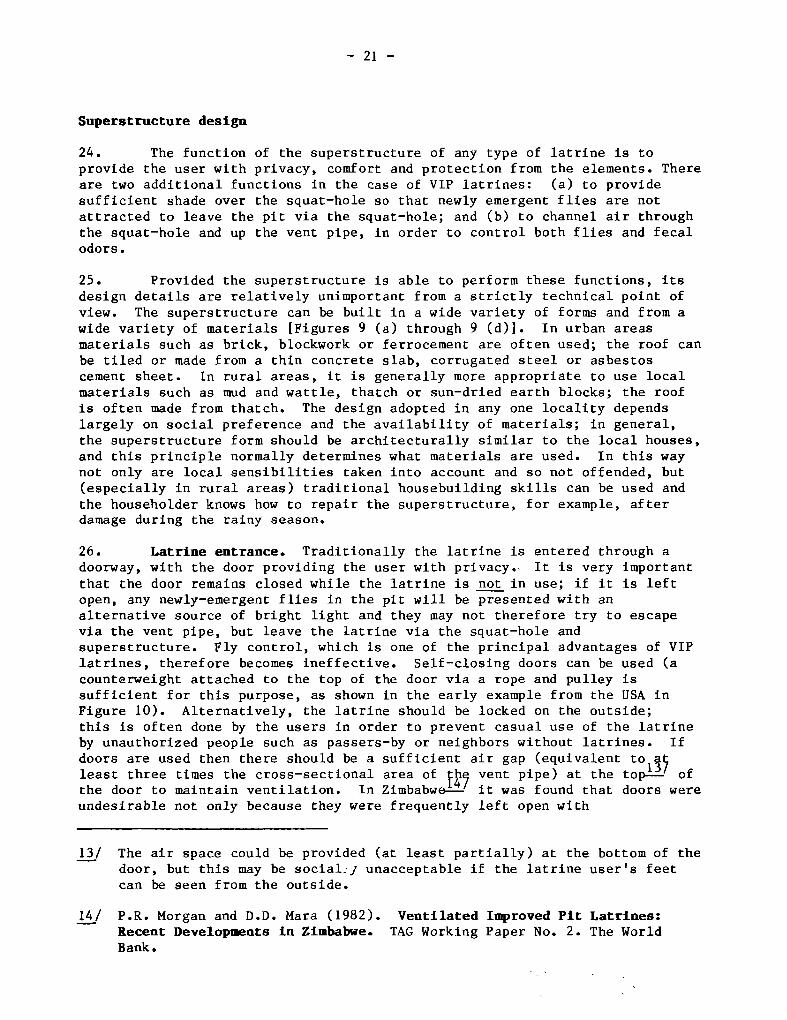
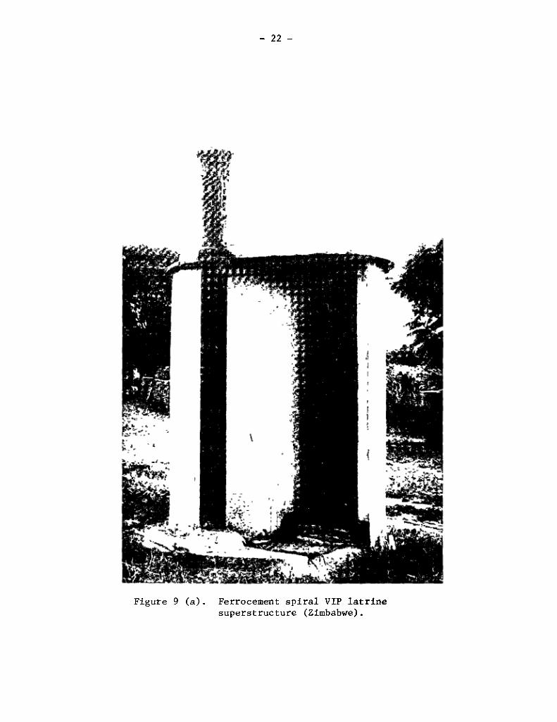
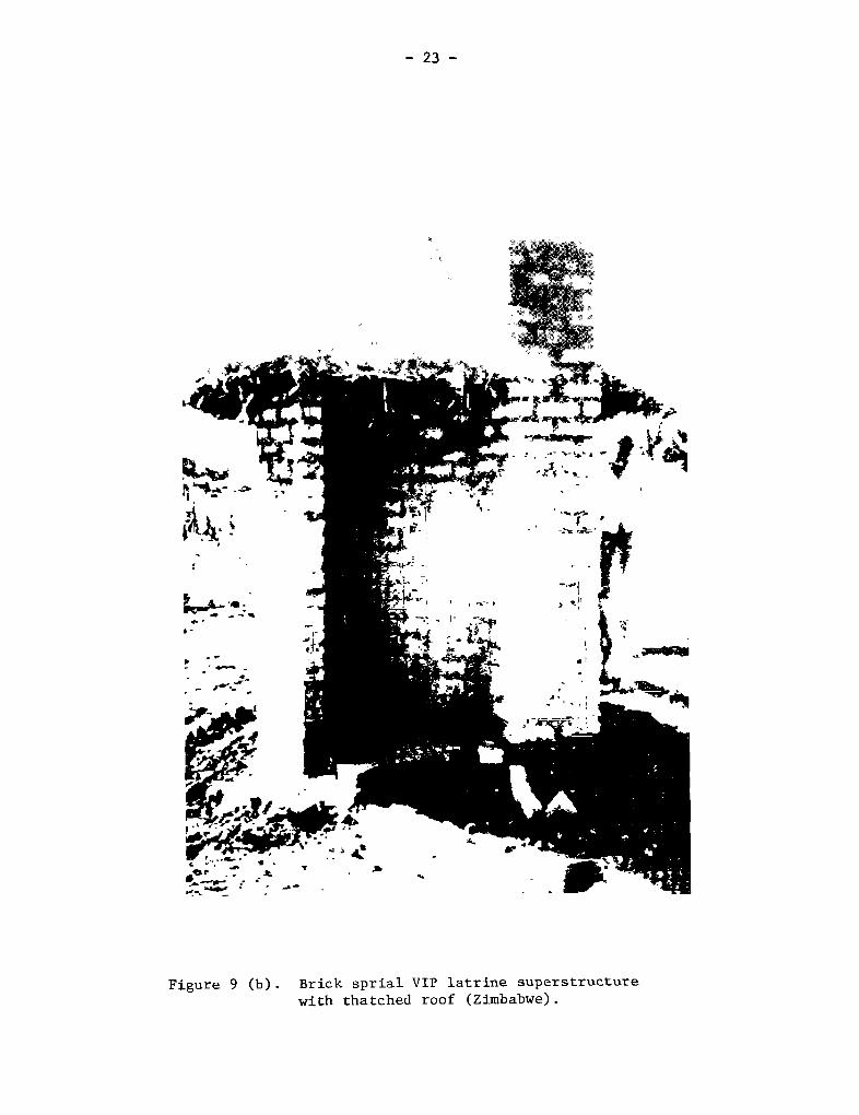
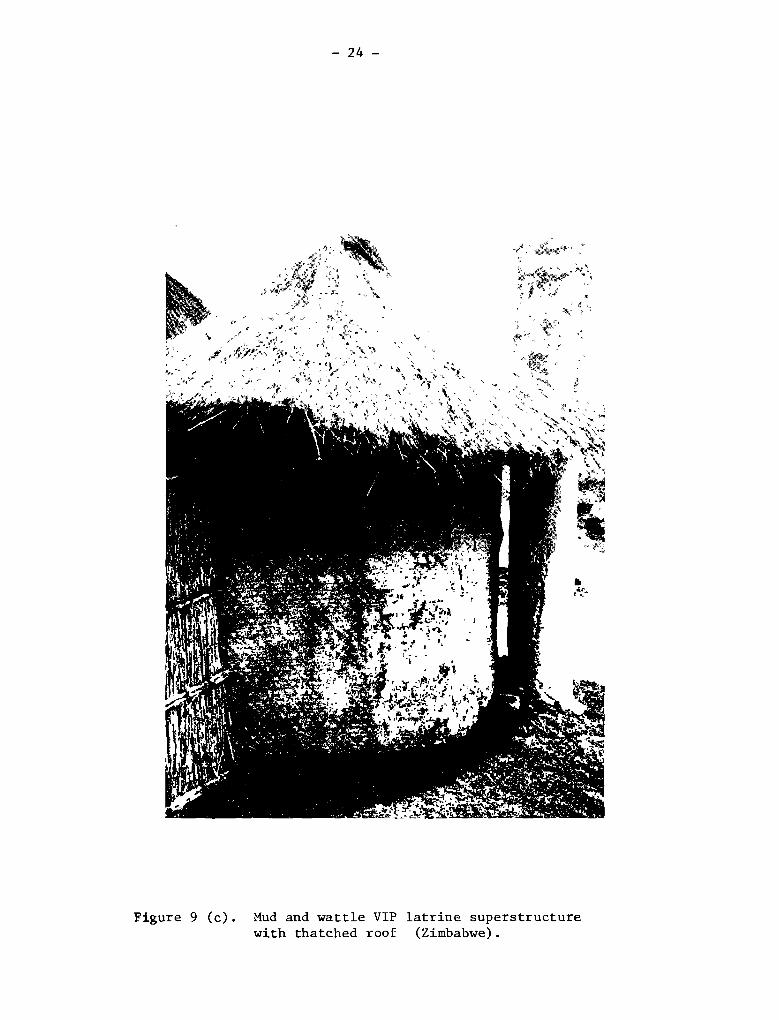
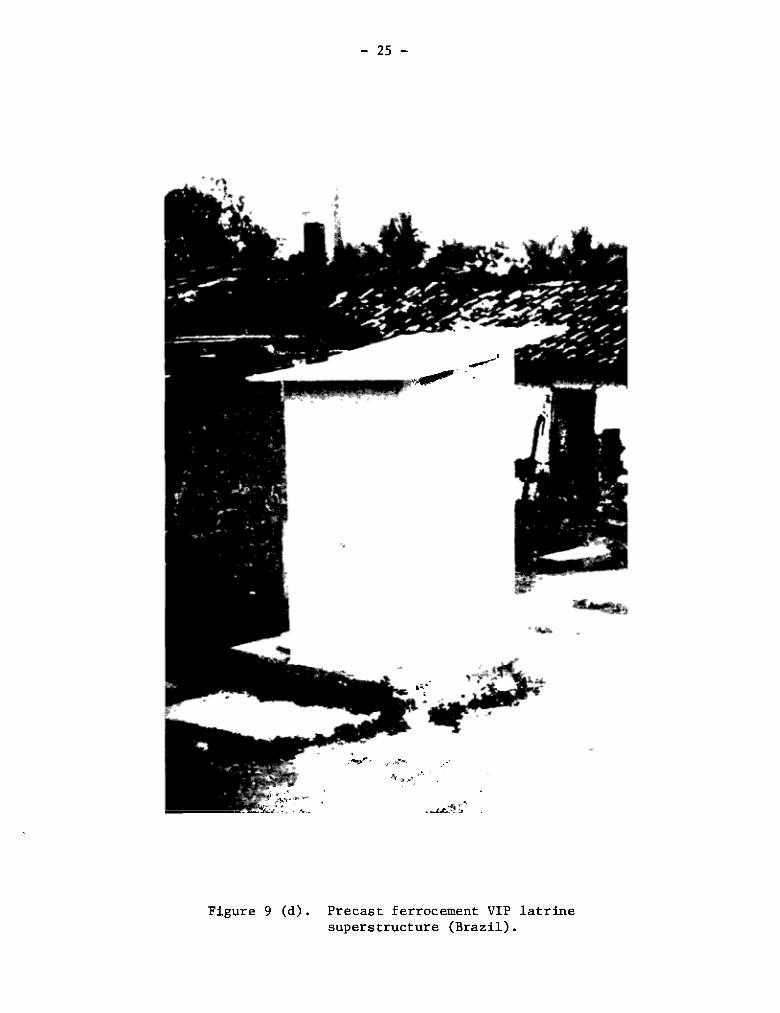
25. Provided the superstructure is able to perform these functions, itsdesign details are relatively unimportant from a strictly technical point ofview. The superstructure can be built in a wide variety of forms and from awide variety of materials [Figures 9 (a) through 9 Cd)]. In urban areasmaterials such as brick, blockwork or ferrocement are often used; the roof canbe tiled or made from a thin concrete slab, corrugated steel or asbestoscement sheet. In rural areas, it is generally more appropriate to use localmaterials such as mud and wattle, thatch or sun—dried earth blocks; the roofis often made from thatch. The design adopted in any one locality dependslargely on social preference and the availability of materials; in general,the superstructure form should be architecturally similar to the local houses,and this principle normally determ+ines what materials are used. In this waynot only are local sensibilities taken into account and so not offended, but(especially in rural areas) traditional housebuilding skills can be used andthe householder knows how to repair the superstructure, for example, afterdamage during the rainy season.
26. Latrine entrance. Traditionally the latrine is entered through adoorway, with the door providing the user with privacy. It is very importantthat the door remains closed while the latrine is not in use; if it is leftopen, any newly—emergent flies in the pit will be presented with analternative source of bright light and they may not therefore try to escapevia the vent pipe, but leave the latrine via the squat—hole andsuperstructure. Fly control, which is one of the principal advantages of VIPlatrines, therefore becomes ineffective. Self—closing doors can be used Cacounterweight attached to the top of the door via a rope and pulley issufficient for this purpose, as shown in the early example from the USA inFigure 10). Alternatively, the latrine should be locked on the outside;this is often done by the users in order to prevent casual use of the latrineby unauthorized people such as passers—by or neighbors without latrines. 1fdoors are used then there should be a sufficient air gap (equivalent to1~Çleast three times the cross—sectional area of vent pipe) at the top—’ ofthe door to maintain ventilation. In Zimbabwe—’ it was found that doors wereundesirable not only because they were frequently lef t open with
13/ The air space could be provided (at least partially) at the bottom of thedoor, but this may be social~’y unacceptable if the latrine user’s feetcan be seen from the outside.
14/ P.R. Morgan and D.D. Mara (1982). Ventilated Iniproved Pit Latrines:Recent Developaents in Zimbabwe. TAG Working Paper No. 2. The WorldBank.
— 22 —
Figure 9 (a). Ferrocement spiral VIP latrinesuperstructure (Zimbabwe).
— 23 —
Figure 9 (b). Brick sprial VIP latrine superstructurewith thatehed roof (Zimbabwe).
— - tt__ ___ttits•a
t_t -
4- r~L1~t
--
t 4..-
~--1) ‘t
al
•1- +
4-er + . t
:y -b
— 24 —
Figure 9 (c). Mud and wattle VIP latrine superstructurewith thatched roof (Zimbabwe).
— 25 —
Figure 9 (d). Precast ferrocement VIP latrinesuperstructure (Brazil).
—t-’
t t
tt_t t~—
— +
tt/ ++trt~
t t~tt ttutt
tt

— 26 —
Vent with fly screen
Pit ventilatorflue at east 4”
Tight fittingself closingseat cover
Metal seat supportEarth backfill
Figure 10. Early pit latrine design from the UnitedStates showing self—closing door, [Reproducedby courtesy of John Wiley Inc. from F.B, Wright,“Rural Water Supply and Sanitation”, 1939.]
Fly screen
Tight fittingself closing
door
Rough lumber~ or open joint\~~\masonry
At least 2’* ~
\‘~GrOUfldwater table level\ \\ \ \‘~\‘ \\\~ •~\~\‘‘‘ \
— 27 —
resultant poor fly—control, but also because wood is expensive, hinges rustand occasionally the doors were removed and chopped up for firewood. Thesuperstructure was then redesigned with a spiral form to avoid the need fordoors [Figure 9 (see page 22); see also Annex II].
Vent pipe design
27. Vent pipes of a wide variety of different materials have been usedsuccessfuily: for example, asbestos cement (AC), polyvinyl chioride (PVC),unplasticized PVC (uPVC), bricks, blockwork, cement—rendered reeds, cement—rendered hessian supported on steel mesh, and even anthlll soil;large diameter bamboo with the cell dividers removed could also be used.Methods for the construction of cement—rendered reed and hessian pipes andother essentially rural vent pipes are described in paragraphs 30—32. Whatevermaterial Is used, its durability (inciuding corrosion resistance),avallability, cost and ease of construction are important factors. Thus, ventpipes made, for example, from thin gaivanized steel sheets are not recommendedas they are prone to corrosion, especially in humid areas. PVC pipes becomebrittle when exposed to high sunhight intensitles, and thus it is better touse PVC pipe made with a special stabillzer to prevent damage by ultr~—i~ioletradiation; however, this grade of PVC may not be generally avaIlable.—~-’ Costis particularly Important in rural VIP latrines; for example, the use of a PVCpipe, rather than a cement—rendered reed ~ more than doubies the cost of amud and wattle latrine in rural Zimbabwe.—’
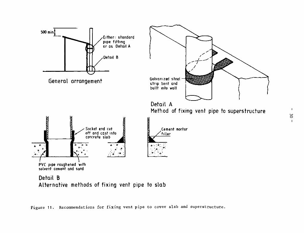
28. Length. The vent pipe should be sufficiently long so that the roofdoes not interfere wlth the action of the wind across the top of the ventpipe. WIth flat roofs, the top of the vent pipe should be at least 500 mmhigher than the roof, and in the case of sloping roofs the vent pipe shouldalso be 500 mm above the highest point of the roof. When the roof is madefrom thatch and shaped conically, the vent pipe should be at least as high asthe apex of the roof.
29. Diameter. The internal diameter of the vent pipe depends on therequired venting velocity necessary to achieve the recommended ventilation
15/ In Zimbabwe It bas been found that PVC pipe manufactured to CentralAfrican Standard K21, “Unplasticized polyvinyl chioride pressure pipe”,(Standards Assoclation of Central Africa, Harare, 1971) performs moresatisfactorily than that manufactured to the less stringent requirementsof British Standard BS 3505 or ISO Standard 3127. See also R.W. Doughty,LLPVC pipes and fictings for hot cliinates, in: Institutlon of PublicHealth Englneers 1982 Handbook, London.
16/ P.R. Morgan and D.D. Mara (1982). Ventilated Iiiproved Pit Latrlnes:Recent Developments in Zimbabwe. TAG Working Paper No. 2. The WorldBank.
— 28 —
rate of 20 m3/hrJ_Z-”, and this In turn depends on such factors as the iriternalsurface roughness of the plpe and its length (which determine the frictionlosses), the head loss through the flyscreen and squat—hole mosquito trap (1fany), and the wind direction. Thus cement—rendered reed vent pipes, forexample, need to have a much larger diameter than AC or PVC pipes since theirInternal roughnessis considerably greater; brick vent pipes, which have asquare cross—section, also need to be larger not only because the roughness isgreater but also because a square cross—?~tion is inherently less efflclentthan a circular one in inducing updraft.—2-’ Current recommendations for theminImum internal size of vent pipes are as foliows:
AC or PVC 150 mm diameterBrick 230 mm squareCement—rendered reed or hessian 230 mm diameter(and other rural types)
In exposed locations where wind speeds are greater than 3 in/s, the minimumdiameter of AC and PVC pipes may be reduced to 100 mm, and to 200 mm in thecase of “rural” vent pipes.
Fabrication of rural vent pipes
30. Ce~nt—rendered reed vent pipes. Local reeds, approximately 1 cmdiameter, are tled together with wire or string to form a mat measuring 2.5 inby 1 m. The mat is then rolled around four or five rings of green saplings toform a tube of some 30 cm external diameter. The flyscreen is then fixed toone end. Cement mortar Cl part cement, 3 parts sand) Is applied to the tubealong Its entire length but only around half its circumference; when this hashardened, the vent pipe is fixed in position wIth the mortared half next tothe latrine superstructure and the other (outer) side then piastered withcement mortar. Thin poles or bamboo sticks may be used instead of reeds.Larger bamboo sticks, split longitudinally into 1 — 2 cm wide strips may alsobe used.
31. Cement—rendered hessian and wire—mesh vent pipes. Spot—welded mildsteel mesh (4 min bars at 100 mm centers), 2.5 m long and 0.8 m wide, is rolledInto a tube to give an Internal diameter of approxImately 25 cm. Hessian orjute fabric is then tightly stltched around the outside of the tube, and theflyscreen fixed to one end by stitching with string or thin galvanized wire.Cement mortar (1 part cement, 2 parts sand) is then applied by brush to thehessian surface in thin layers, to a fInal thickness of at least 1 cm. Thevent pipe is then fixed In place.
17/ B.A. Ryan and D.D. Mara, Pit Latrine Ventilatlon: Pield InvestigationPlethodology, TAG Technical Note No. 4; and Ventilated Improved PitLatrines: Vent Pipe Design Guidelines, TAG TechnIcal Note No. 6.
18/ D.R. Wilis, E.W.G. Dance and G.T. Blench (1959). The Design andPerformance of Natural Flue Terminations. Gas Council ResearchCommunicatlon No. GC61. London: Instltute of Gas Englneers.

— 29 —
32. Antbili soil vent pipes. Well—kneaded anthili soil Is rolled Into“sausages”, approxlmately 10 cm in diameter and 90 cm long, whlch are madeinto circies of approxlmately 28 cm internal diameter. The vent plpe isconstructed in situ from these cIrcles; vertical reinforcement wlth shortlengths of reed of thin bamboo (or other suitable material) can be driven inbetween adjacent circies as constructlon proceeds. When the vent pipe hasbeen built to a helght of 2.5 in, Its external surface Is smoothed off byadding more soil; the flyscreen is attached to the upper end and then a thincoat of cement mortar (1 part cement, 6 parts sand) appiled.
33. External surface preparation. In areas where the mean wind speed isless than 0.5 in/s, the external surface of the vent pipe should be palntedblack In order to increase the absorption of solar radiation and thus themagnltude of the thermally—induced venting velocity. In areas where the meanwind speed Is above 0.5 in/s the color of the vent pipe is not Important.
34. Locatlen. The latrines should be located at least 2 in away fromoverhanging branches and anythlng else that might impede the action of thewind across the top of the vent pipe. The vent pipe Itself should be locatedon the wlndward side of the superstructure, as also should any openings(doorways, windows, gaps between the roof and walls). 1f, however, It isimpossible to have both vent pipe and any openings on the windward side, atleast one of them must be (and this should preferably be the openings). It isextremely Important to avoid openings on opposite sides, as this wouldsignlficantly reduce the pressure differences causing updraft In the ventpipes. In latrines deslgned with doors the minimum size of ventllationopening(s) should be at least three tlmes the cross—sectional area of the ventpipe (to allow for head losses in the superstructure).
35. In general, the vent pipe should be located on the outside of thesuperstructure, since It is more difficult and expensive to ensure a rainproofand wind—tlght seal between the roof and a vent pipe going through It.Moreover, in very sheltered areas, thermally—Induced ventilation may be moreimportant than that due to the wind, and thus the vent pipe must be placedoutside the superstructure on Its sunny slde and palnted black. However, Inurban areas especially, external vent pipes could be subject to damage byvandals, aithough, as yet, there have been no reports of this happening.
36. The vent plpe must be rigidly flxed to the superstructure and thecover slab; design recommendations are given in Figure 11.
37. Flyscreen specification. The purpose of the flyscreen is to preventthe passage of files and mosquitoes; therefore the mesh aperture must not belarger than 1.2 mm x 1.5 mm (smaller apertures are not recommended as theywIll resuit In decreased ventilat on rates, due to Increased frlctlonallosses). The flyscreen must be made of corrosion—resistant materlal that isable to withstand Intense rainfali, high temperatures and strong sunlight.PVC—coated glass—flber screens have been extensively used in Zimbabwe as theyare Inexpensive (around US$ 0.50 per latrine), but after five years or SO theybecome very brittle and susceptlble to da~ge by birds and lizards. It ispreferable to use stainless steel screens—’ which last indefinitely;
19/ For example, 16 mesh, 28 s.w.g. screening.
Cement mortar________ ~,~fiUer
Detail BALternative methods of fixing vent pipe to slab
500min~[
A
B
General arrangement Gcilvanized steelstrip bent andbuilt info wall
Detail 4Method of fixing vent pipe to superstructure
Socket end cut1—” off and cast info
concrete stab0 00
0~.
PVC pipe roughened wifhsoLvent cement and send
c
Figure 11. Recommendations for fixing vent pipe to cover slab and superstructure.
— 31 —
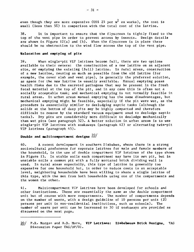
even though they are more expensive (uS$ 25 per in2 ex works), the cost is
small (iess than 5%) In comparison with the total cost of the latrine.
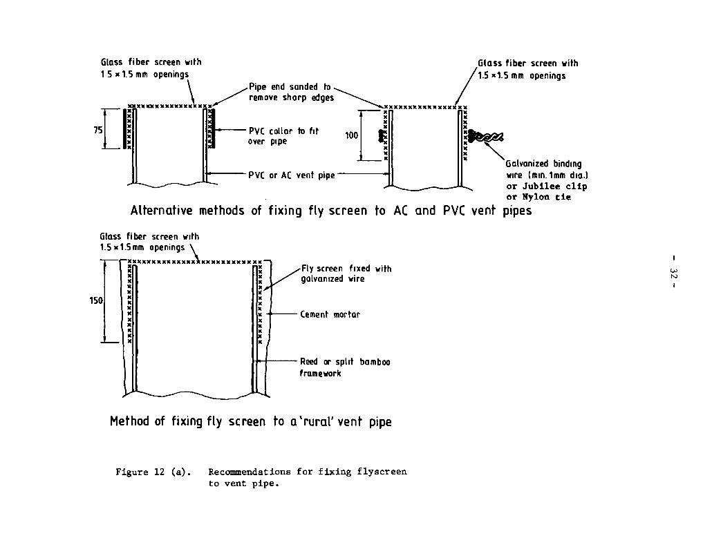
38. It is important to ensure that the flyscreen Is tlghtly fixed to thetop of the vent pipe In order to prevent access by insects. Design detailsare shown in Figure l2(a) and (b). When the flyscreen is in place thereshould be no obstructlon to the wind flow across the top of the vent pipe.
Relocation and emptying of pits
39. When single—pit VIP latrines become full, there are two optionsavailable to their owners: the construction of a new latrine on an adjacentsite, or emptying the existing (full) latrine. In rural areas, constructionof a new latrine, reusing as much as possible from the old latrlne (forexample, the cover slab and vent pipe), is generally the preferred solution,as space for the new latrlne is usually avallable. Manual emptylng poseshealth rlsks due to the excreted pathogens that may be present in the freshfecal material at the top of the pit, and In any case this is often not asoclally acceptable task; and mechanlcal emptylng Is not normally feasible inrural areas. In urban areas manuai emptying has the same disadvantages, butmechanlcal emptylng mlght be feaslble, especlally 1f the pit were wet, as theprocedure is essentially slmilar to desludging septic tanks (although thesolids at the bottom of deep plts may be hlghly compacted and thereforedifficult to remove by the standard vacuum equipment used to desludge septictanks). Dry pits are considerably more dlfflcult to desludge mechanicallythan wet pits (see paragraph 52). A better solution in urban areas is to usesingle—pit VIP latrines with soakaways (paragraph 42) or alternating twin—pitVIP latrines (paragraph 45).
Double and nilticompartment designs
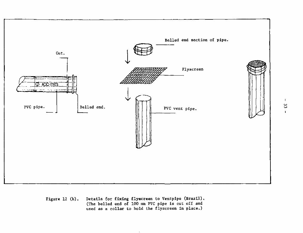
40. A recent development In southern Zimbabwe, where there is a strongsociocultural preference for separate latrines for male and female members ofthe household, is the use of double compartment VIP latrines of the type shownin Figure 13. In stable solls each compartment may have Its own pit, but Inunstable soils a common pit with a fully mortared brick dividing wall isused. In rural areas especially, this type of latrlne is generally tooexpensive for one household but, in order to reduce costs to an acceptablelevel, neighboring households have been willing to share a single latrine ofthis type, with the men from both households using one of the compartments andthe women the other.
41. Multicompartment VIP latrines have been developed for schools andother institutions. These are essentially the same as the double compartmentunlt but of course wlth more compartments. The number of compartments dependson the number of users, with a design guideline of 10 persons per unit (20persons per unit in non—residentlal institutions, such as schools). Thenumber of users per unlt can be Increased to 30 1f soakaways are provided asdiscussed on the next page.
20/ P.R. Morgan and D.D. Mara, VIP Latrines: Zimbab,ean Brick Designs, TAGDiscussion Paper TAG/DP/01.
Glass fiber screen with1 S x 1.5 mm openings
xxxxxxxxXxx
Galvanized bindingwire (min.lmm dia.)or Jubilee clipor Nylon tie
Glass fiber screen with1.5 xl.Smm openings
Met hod of fixing fLy screen to a’ruraL’ vent pipe
(.~)
Figure 12 (a). Recommendations for fixing flyscreento vent pipe.
Glass fiber screen with
Pipe end sanded toedges~ /1.5 xis mm
_____ xXXxxxXFI flxxli lixXli ‘lx
PVC collar to fit loot ~ll lI!~2~X
xli 11)6over pipe jxli lixXII lix
Alfernative methods of fixing fly screen to AC and PVC vent pipes
PVC or AC vent pipe II
cxxxxxxxxxxx xxxxxxxxxxw ith
Cement mortar
Reed iw split bambooframework
Cu t.
PVC pipe. Belled end.
Belled end section of pipe.
Flyscreen
PVC vent pipe.
Figure 12 (b). Details for fixing flyscreen to Ventpipe (Brazil),(The belled end of 100 min PVC pipe is cut of f andused as a collar to hold the flyscreen in place.)
~1~
— 34 —
r.0)
-cENl
ci
•T-l
4.)
cc
p.l‘-4
alE1-J)-1
E0
al
,0
0
en‘-4
al
00~-1
— 35 —
Des igus with soakaways
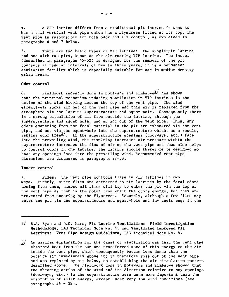
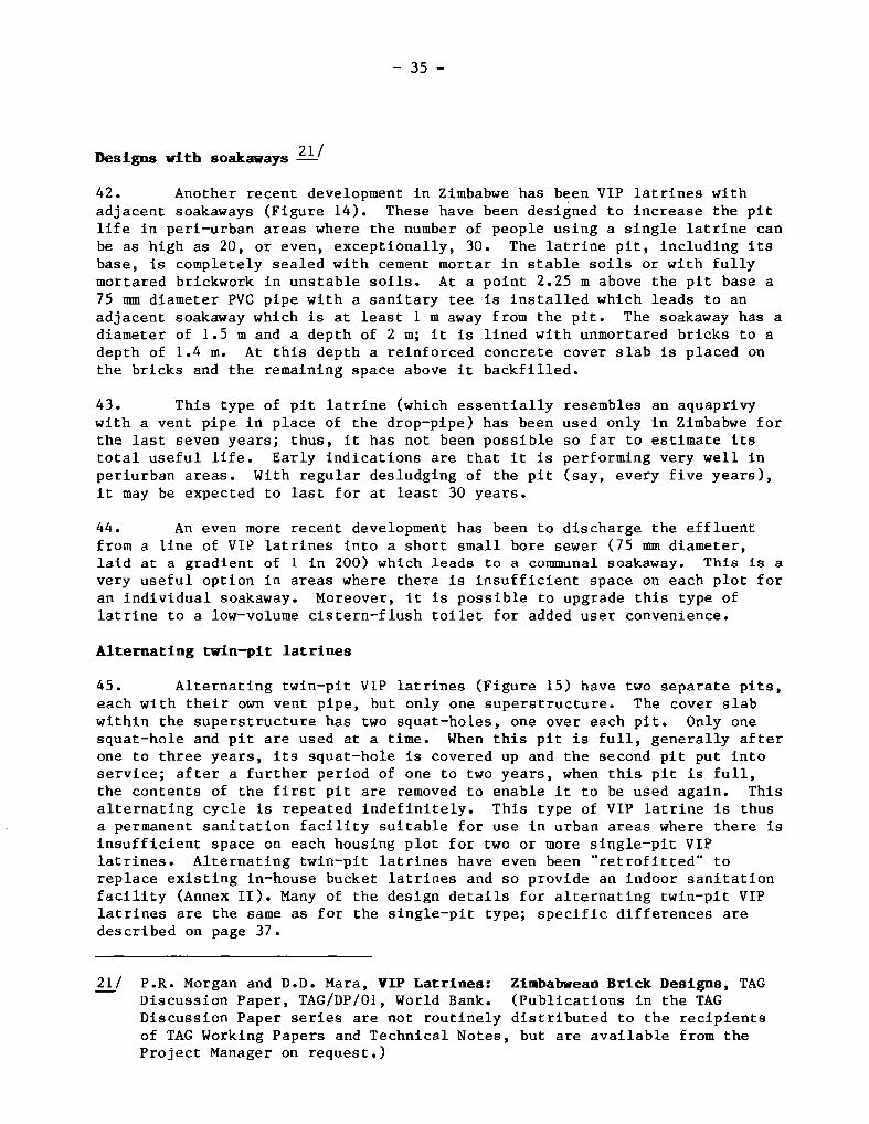
42. Another recent development in Zimbabwe has been VIP latrines withadjacent soakaways (Figure 14). These have been designed to increase the pitlife in peri—urban areas where the number of people using a single latrine canbe as high as 20, or even, exceptionally, 30. The latrine pit, including itsbase, is completely sealed with cement mortar in stable soils or with fullymortared brickwork in unstable soils. At a point 2.25 m above the pit base a75 mm diameter PVC pipe with a sanitary tee is installed which leads to anadjacent soakaway which is at least 1 m away from the pit. The soakaway has adiameter of 1.5 m and a depth of 2 m; it is lined with unmortared bricks to adepth of 1.4 m. At this depth a reinforced concrete cover slab is placed onthe bricks and the remaining space above it backfilled.
43. This type of pit latrine (which essentially resembles an aquaprivywith a vent pipe in place of the drop—pipe) has been used only in Zimbabwe forthe last seven years; thus, it has not been possible so far to estimate itstotal useful life. Early indications are that it is perform+ing very well inperiurban areas. With regular desludging of the pit (say, every five years),it may be expected to last for at least 30 years.
44. An even more recent development has been to discharge the effluentfrom a line of VIP latrines into a short small bore sewer (75 mm diameter,laid at a gradient of 1 in 200) which leads to a communal soakaway. This is avery useful option in areas where there is insufficient space on each plot foran individual soakaway. Moreover, it is possible to upgrade this type oflatrine to a 10w—volume cistern—flush toilet for added user convenience.
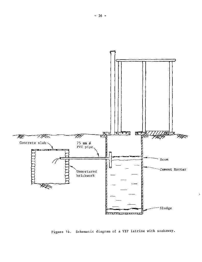
Alternating twin—pit latrines
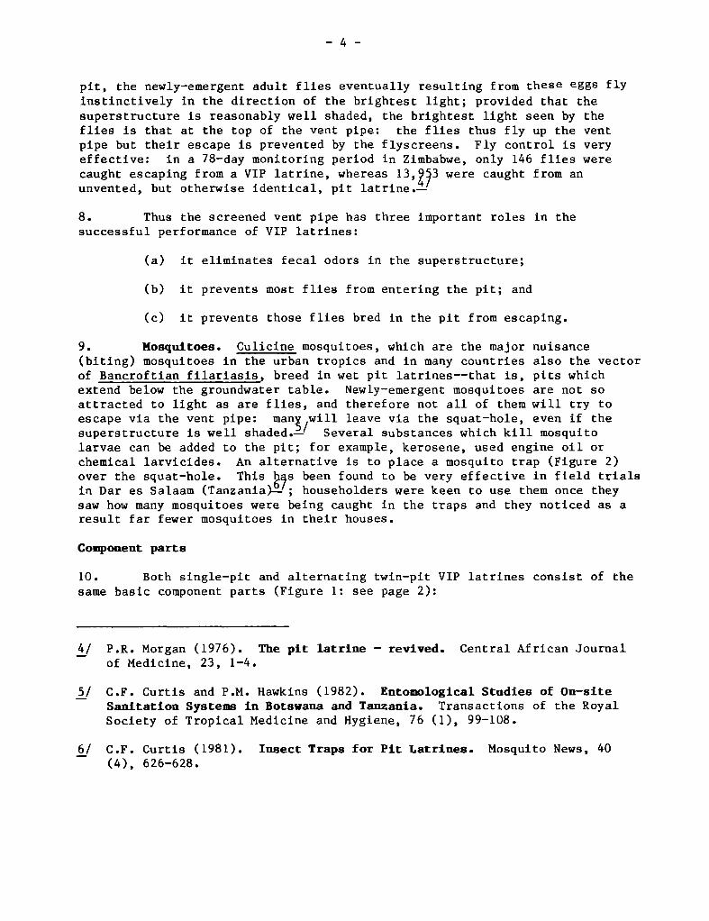
45. Alternating twin—pit VIP latrines (Figure 15) have two separate pits,each with their own vent pipe, but only one superstructure. The cover slabwithin the superstructure has two squat—holes, one over each pit. Only onesquat—hole and pit are used at a time. When this pit is full, generally afterone to three years, its squat—hole is covered up and the second pit put intoservice; after a further period of one to two years, when this pit is full,the contents of the first pit are removed to enable it to be used again. Thisalternating cycle is repeated indefinitely. This type of VIP latrine is thusa permanent sanitation facility suitable for use in urban areas where there isinsufficient space on each housing plot for two or more single—pit VIPlatrines. Alternating twin—pit latrines have even been “retrofitted” toreplace existing in—house bucket latrines and so provide an indoor sanitationfacility (Annex II). Many of the design details for alternating twin—pit VIPlatrines are the same as for the single—pit type; specific differences aredescribed on page 37.
21/ P.R. Morgan and D.D. Mara, VIP Latrines: Zimbabwean Brick Designs, TAGDiscussion Paper, TAG/DP/01, World Bank. (Publications in the TAGDiscussion Paper series are not routinely distributed to the recipientsof TAG Working Papers and Technical Notes, but are available from theProject Manager on request.)
- 36 -
brickwork
S cum
Mortar
S lud ge
Figure 14. Schematic diagram of a VIP latrine with soakaway.
IT, ~ ~. t’ ~ —~
~it*t~,
S- r
-a!‘ ~ ~1~b~j~: 1 -‘
t-
.~~
1 :i~~ ~ T:!’. ~
?‘prn-:~-
~
ÏL1k~.
S —‘-- —-1
TT~’-~
~)t~~
— - •--— -
~
~j~•
-4
mr L_Jr.;:~1~t:it~
Figure 15. Alternating twin—pit VIP latrine (Tanzania).
—38 —
Pit function and design
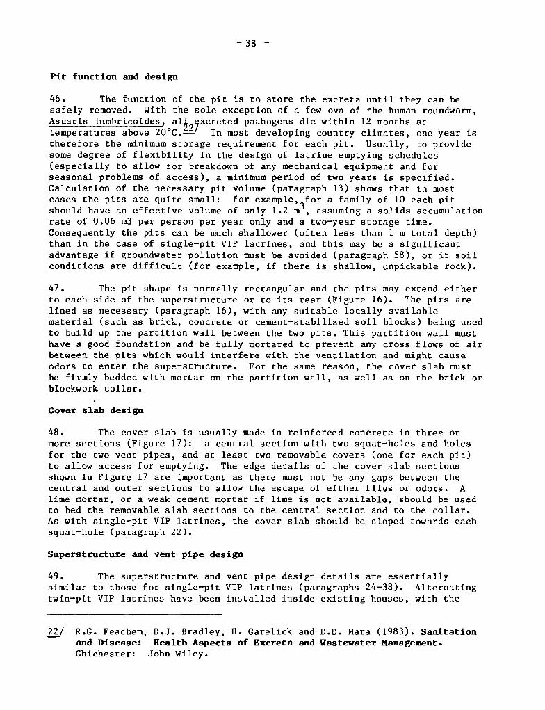
46. The function of the pit is to store the excreta until they can besafely removed. With the sole exception of a few ova of the human roundworm,Ascaris lumbricoides, al~ ~xcreted pathogens die within 12 months attemperatures above 20°C._~?-’ In most developing country climates, one year istherefore the minimum storage requirement for each pit. Usually, to providesome degree of flexibility in the design of latrine emptying schedules(especially to allow for breakdown of any mechanical equipment and forseasonal problems of access), a minimum period of two years is specified.Calculation of the necessary pit volume (paragraph 13) shows that in mostcases the pits are quite small: for example,3for a family of 10 each pitshould have an effective volume of only 1.2 m , assuming a solids accumulationrate of 0.06 m3 per person per year only and a two—year storage time.Consequently the pits can be much shallower (often less than 1 m total depth)than in the case of single—pit VIP latrines, and this may be a significantadvantage if groundwater pollution must be avoided (paragraph 58), or if soilconditions are difficult (for example, if there is shallow, unpickable rock).
47. The pit shape is normally rectangular and the pits may extend eitherto each side of the superstructure or to its rear (Figure 16). The pits arelined as necessary (paragraph 16), with any suitable locally availablematerial (such as brick, concrete or cement—stabilized soil blocks) being usedto build up the partition wall between the two pits. This partition wall musthave a good foundation and be fully mortared to prevent any cross—flows of airbetween the pits which would interfere with the ventilation and might causeodors to enter the superstructure. For the same reason, the cover slab mustbe firmly bedded with mortar on the partition wall, as well as on the brick orblockwork collar.
Cover slab design
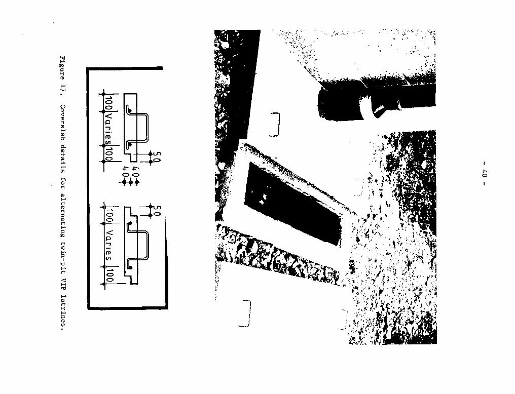
48. The cover slab is usually made in reinforced concrete in three ormore sections (Figure 17): a central section with two squat—holes and holesfor the two vent pipes, and at least two removable covers (one for each pit)to allow access for emptying. The edge details of the cover slab sectionsshown in Figure 17 are important as there must not be any gaps between thecentral and outer sections to allow the escape of either flies or odors. Alime mortar, or a weak cement mortar if lime is not available, should be usedto bed the removable slab sections to the central section and to the collar.As with single—pit VIP latrines, the cover slab should be sloped towards eachsquat—hole (paragraph 22).
Superstructure and vent pipe design
49. The superstructure and vent pipe design details are essentiallysimilar to those for single—pit VIP latrines (paragraphs 24—38). Alternatingtwin—pit VIP latrines have been installed inside existing houses, with the
22/ R.G. Feachem, D.J. Bradley, H. Garelick and D.D. Mara (1983). Sanitationand Disease: Health Aspects of Excreta and Wastewater Management.Chichester: John Wiley.
— 39 —
-
~oo,-
0
- ~—
,4
,4
~
0
Alternative pit geometries for alternating-Ii, n-ir VT~1~i-r-fn
Figure 16.
OQ
‘1
0
0
0‘-1CDI-i
0-
0
Ç~)
I-iCD
fr~0‘1
I-i
0
S
S
-cl
H
1-~
‘~1I-~.S0CD
ci
p
ID

— 41 —
pits accessible from outside (Annex II); in some cultures such an arrangementmay be socially preferable to external superstructures.
Multicoapartnent units
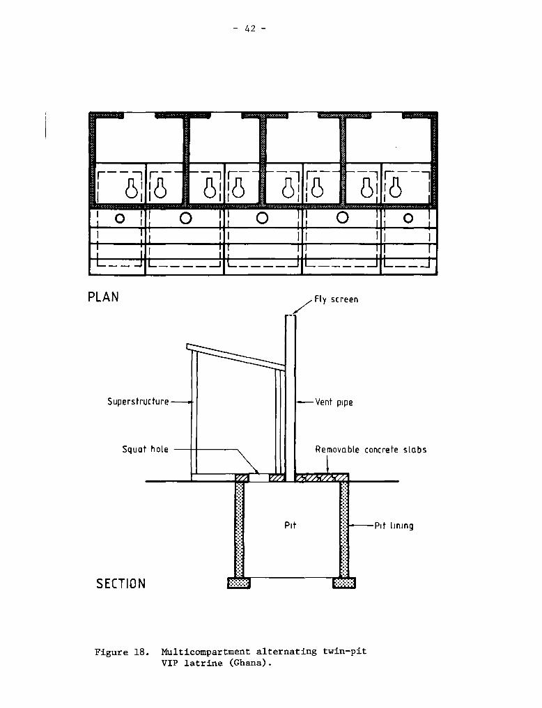
50. Multicompartment alternating twin—pit VIP latrines have beendeveloped in Ghana for use in rural institutions such as schools and as avillage communal sanitation facility (Figure 18). All pits, except the twoend ones, serve two squat—holes in adjacent compartments; for good odorcontrol it has been found necessary for these pits to be ventilated by a150 mmdiameter vent pipe. The two end pits, being only half the size of theothers and serving only one squat—hole, are ventilated by 100 mm diameterpipes. In all other respects multicompartment units are designed in the sameway as single units.
Eaptying of pits
51. Manual removal of the humus—like material in the pits, which is atleast two years old, presents no health risk as all the excreted pathogens arenon—viable, except for a few Ascaris ova. Discussions with the intendedbeneficiaries (or their leaders) prior to the installation of alternatingtwin—pit VIP latrines may indicate that they consider the handling of the pitcontents to be a socially—abhorrent task. Once however the two—yeartransformation of fresh excreta to harmless humus has been witnessed by theusers, their attitudes may change. 1f this does not not happen, then pitemptying is best left to the municipality (or other appropriate localgovernment agency) for ei ther manual or mechanical emptying by itsemployees. The contents so removed can be disposed of in sanitary landfillsor, preferably, reused on agricultural land.
52. Mechanical emptying of wet pits is easily done with standard septictank emptying equipment, but removal of dry materials presents moredifficulty. Since most alternating twin—pit VIP latrines have shallow pits(paragraph 46), dry pits will be common. Research q9onsored by TAG and theInternational Reference Centre for Wastes DisposalL~-’ indicates that air—dragsystems are the only currently available option for emptying dry pits; recentfield trials in B~qwana have shown that suitable equipment is now availablefor this purpose.—.’
23/ P.M. Hawkins (1982). Rmptying on—site eicreta disposal systeas indeveloping countries: an evaluatlon of the problems. IRCWD NewsNo. 17. Duebendorf, Switzerland: International Reference Centre forWastes Disposal.
24/ A report on these trials, held in Gaborone during October 1983—February1984, will shortly be issued by TAG and the International ReferenceCentre for Wastes Disposal, Duebendorf, Switzerland. See also BREInformation Paper No. 84: BREVAC: a MechanisedMethod of EaptyingSanitation Chainbers, (Building Research Establishment, Watford, England,1984), which gives a brief description of one of the vacuum tankerstested in these trials.
— 42 —
PLAN Fly screen
SECTION
—Vent pipe
Removoble
Multicompartment alternating twin—pitVIP latrine (Ghana).
Superstructure
Squat hote
?21 /
concrete slabs
Pit —Pit lining
Figure 18.
— 43—
APPLICABIL 1fl AND CONSTRAINTS
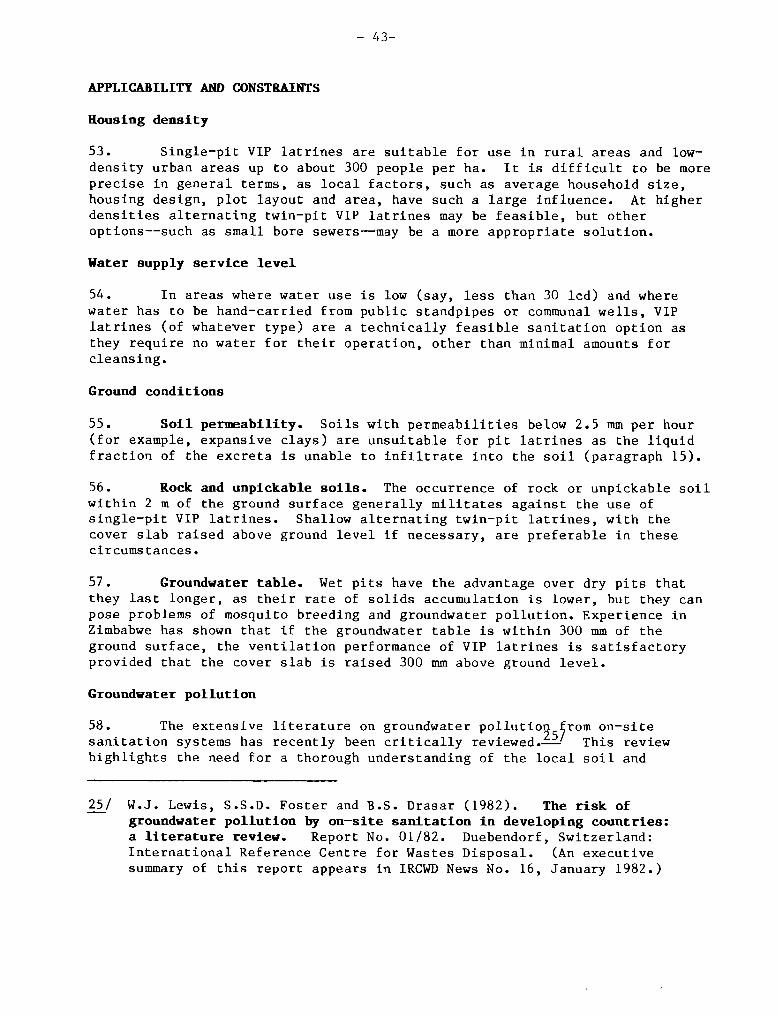
Rousing density
53. Single—pit VIP latrines are suitable for use in rural areas and low—density urban areas up to about 300 people per ha. It is difficult to be moreprecise in general terms, as local factors, such as average household size,housing design, plot layout and area, have such a large influence. At higherdensities alternating twin—pit VIP latrines may be feasible, but otheroptions——such as small bore sewers——may be a more appropriate solution.
Water supply service level
54. In areas where water use is low (say, less than 30 lcd) and wherewater has to be hand—carried from public standpipes or communal wells, VIPlatrines (of whatever type) are a technically feasible sanitation option asthey require no water for their operation, other than minimal amounts forcleans ing.
Ground conditions
55. Soil permeability. Soils with permeabilities below 2.5 mm per hour(for example, expansive clays) are unsuitable for pit latrines as the liquidfraction of the excreta is unable to infiltrate into the soil (paragraph 15).
56. Rock and unpickable soils. The occurrence of rock or unpickable soilwithin 2 m of the ground surface generally militates against the use ofsingle—pit VIP latrines. Shallow alternating twin—pit latrines, with thecover slab raised above ground level if necessary, are preferable in thesecircums tances.
57. Groundwater table. Wet pits have the advantage over dry pits thatthey last longer, as their rate of solids accumulation is lower, but they canpose problems of mosquito breeding and groundwater pollution. Experience inZimbabwe has shown that if the groundwater table is within 300 mm of theground surface, the ventilation performance of VIP latrines is satisfactoryprovided that the cover slab is raised 300 mm above ground level.
Croundwater pollution
58. The extensive literature on groundwater pollutio95~rom on—sitesanitation systems has recently been critically reviewed.— This reviewhighlights the need for a thorough understanding of the local soil and
25/ W.J. Lewis, S.S.D. Foster and B.S. Drasar (1982). The risk ofgroundwater pollution by on—site sanitation in developing countries:a literature review. Report No. 01/82. Duebendorf, Switzerland:International Reference Centre for Wastes Disposal. (An executivesummary of this report appears in IRCWD News No. 16, January 1982.)
- 44-
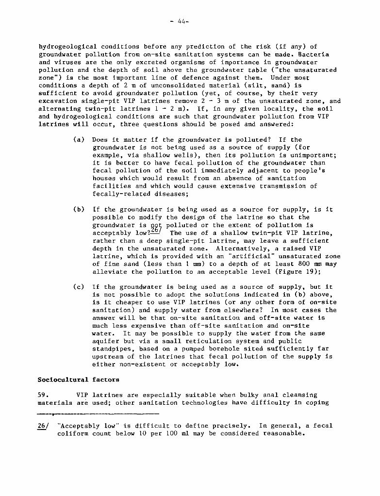
hydrogeological conditions before any prediction of the risk (if any) ofgroundwater pollution from on—site sanitation systems can be made. Bacteriaand viruses are the only excreted organisms of importance in groundwaterpollution and the depth of soil above the groundwater table (“the unsaturatedzone”) is the most important line of defence against them. Under mostconditions a depth of 2 m of unconsolidated material (silt, sand) issufficient to avoid groundwater pollution (yet, of course, by their veryexcavation single—pit VIP latrines remove 2 — 3 m of the unsaturated zone, andalternating twin—pit latrines 1 — 2 m). 1f, in any given locality, the soiland hydrogeological conditions are such that groundwater pollution from VIPlatrines will occur, three questions should be posed and answered:
(a) Does it matter if the groundwater is polluted? 1f thegroundwater is not being used as a source of supply (forexample, via shallow wells), then its pollution is unimportant;it is better to have fecal pollution of the groundwater thanfecal pollution of the soil immediately adjacent to people’shouses which would result from an absence of sanitationfacilities and which would cause extensive transmission offecally—related diseases;
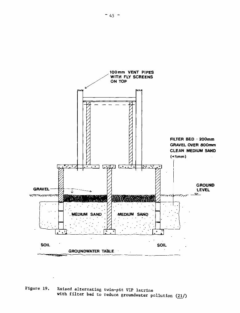
(b) 1f the groundwater is being used as a source for supply, is itpossible to modify the design of the latrine so that thegroundwater is polluted or the extent of pollution isacceptably low?—’ The use of a shallow twin—pit VIP latrine,rather than a deep single—pit latrine, may leave a sufficientdepth in the unsaturated zone. Alternatively, a raised VIPlatrine, which is provided with an “artificial” unsaturated zoneof fine sand (less than 1 mm) to a depth of at least 800 mmmayalleviate the pollution to an acceptable level (Figure 19);
(c) 1f the groundwater is being used as a source of supply, but itis not possible to adopt the solutions indicated in (b) above,is it cheaper to use VIP latrines (or any other form of on—sitesanitation) and supply water from elsewhere? In most cases theanswer will be that on—site sanitation and oft—site water ismuch less expensive than off—site sanitation and on—sitewater. It may be possible to supply the water from the sameaquifer but via a small reticulation system and publicstandpipes, based on a pumped borehole sited sufficiently farupstream of the latrines that fecal pollution of the supply iseither non—existent or acceptably low.
Sociocultural factors
59. VIP latrines are especially suitable when bulky anal cleansing
materials are used; other sanitation technologies have difficulty in coping
26/ “Acceptably low” is difficult to define precisely. In general, a fecalcoliform count below 10 per 100 ml may be considered reasonable.
— 45 —
lOOmm VENT PIPESWITH FLY SCREENSON TOP
SOIL SOIL
FILTER BED : 200mmGRAVEL OVER BOOmmCLEAN MEDIUM SAND(cl mm)
GROUNDLEVEL
Figure 19. Raised alternating twin—pit VIP latrinewith filter bed to reduce groundwater pollution (21/)
________ GROUNDWATER TABLE
— 46 —
with such material. However, in areas where water is used for t~3qpurpose,usually a preferable sanitation option is the pour—flush toilet.—’
60. VIP latrines can be designed for either a sitting or a squattingdefecation posture (paragraph 21). The locally preferred posture should beascertained and the latrine designed accordingly.
61. In societies where an in—house toilet is preferred, VIP latrines canstill be used. Internal VIP latrines, with access to the pit from outside thehouse, have been built in Brazil (single—pit version) and Ghana (alternatingtwin—pit version); details may be found in Annex II.
62. 1f there is a local preference or requirement for separate facilitiesfor male and female household members, then a design similar to that deseribedin paragraph 40 should be adopted; sharing of this facility between adjacenthouseholds, to reduce costs, should be discussed with the community.
DESIGN SEÏLECTION CRITERIA
63. Given that a VIP latrine of some type is the most appropriatesanitation technology for the community under consideration, the designer isfaced with the question: which type of VIP latrine is the most suitable?This section discusses the selection criteria through which the designer cananswer this question. The discussion assumes that all relevant socioculturalrequirements have been assessed.
64. For convenience, this section is divided into two parts:Favorable and Adverse Ground Conditions. Favorable ground conditions referto:
(a) the soil being sufficiently permeable to permit infiltration ofthe liquid fraction of the excreta;
(b) the absence of unpickable rock to the depth to which the pit isto be excavated; and
(c) the groundwater table being sufficiently low so as not to makepit excavation and lining unduly difficult and expensive.
1f these requirements are not all met, then the ground conditions aredescribed as adverse.
Favorable ground conditlons
65. Since single—pit VIP latrines of the kind shown in Figure 1 (see page2) usually cost less than any other type, the designer will normally
27/ D.D. Mara, The Design of Pour—flush Toilets, TAG Technical Note (inpreparation).
— 47 —
commence by assessing whether a design of this k3,nd is feasible.-?.~J Assumingthat a reasonable planning horizon is 20 year~~?4 and that a single—pit VIPlatrine can be expected to last for 10 years,i~-’ the designer must determinewhether there is sufficient space available on each plot for two pit sites.1f there is, then a single—pit ViP latrine system is normally the sanitationoption of choice. One will be built initially and used for the first 10years, after which a second one is built (re—using as much material aspossible from the first) to serve for the second 10 years.
66. However, if the number of users of a single—pit latrine is high (say,more than 10), then the required pit volume may be unacceptabiy large,especially if the solids accumulation rate is high. Under these circumstancesthe designer should assess the comparative feasibilities——technical, socialand economic——of the following options:
(a) an “alternating single—pit” VIP latrine system; this assumesthat there is space for two sites for single—pits with aneffective life of, say, five years; a single—pit VIP latrine isbuilt initially to serve for the first five years, after which asecond single—pit iatrine is built for the next five years; whenthis becomesfull at the end of year 10, the first pit isexcavated and put back into service; a sim~19r operation is doneat the end of year 15 with the second pit;J-&-’
(b) one single—pit VIP latrine which is to be desludged mechanicallyevery 3 — 10 years (several combinations of pit volume andemptying frequency should be investigated so as to arrive at theleast—cost solution);
(c) a single—pit VIP latrine with an individual or communal soakaway(paragraphs 42 and 44); and
(d) an alternating twin—pit VIP latrine which is to be desludged,manually or mechanically, every two to three years.
23/ 1f separate facilities for each sex are required, then these should beprovided. The ensuing discussion assumes, for ease of argument, thatthey are not required.
29/ After 20 years (possibly less) water supply service levels may haveimproved so that other sanitation technologies become more appropriate.
30/ This is not always possible, due to adverse ground conditions or a largenumber of users. On the other hand, single—pit VIP latrines may last for20 years, as in Zimbabwe (Annex II).
31/ This solution is likely to have a lower present value than the otheroptions as listed below, but it should be discussed carefully with thecommunity at the design stage to determine its acceptability and toclarify responsibilities (e.g., are the householders themselves requiredto do all the vzork involved in latrine relocation?).
— 48 —
Figure 20. Raised VIP latrine in high groundwatertable area (Tanzania).
T 4~q•
t’
~.tF
rn~ .ç
~1t~
~
1. -
-t1~
— ç —
— 49 —
Adverse ground conditions
67. Low soil perineability. 1f the soil is insufficiently permea~3~forVIP latrines, then on—site excreta disposal of any ~ is infeasible_-J andoff—slte technologies, such as small bore sewerage,—’ must be considered.
68. Shailow unpickabie rock. Options (a) through (d) in paragraph 66should be evaluated. In many situations option (d) — alternating twin—pit VIPlatrines — will be the choice.
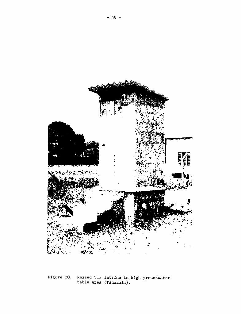
69. High groundwater table. In areas with only a seasonally highgroundwater table, it is generally possible to excavate and line the pitduring the dry season; under these circumstances the ground conditions may beconsidered as favorable and the designer should follow the advice given inparagraphs 63 — 66. The only additional design feature, which is necessary inareas where the groundwater table reaches to within 300 cm of the groundsurface, is the raising of the cover slab some 300 cm above ground level(Figure 20).
70. In areas with permanently high groundwater levels pit excavation instable soils may be relatively easy; a portable pump can be used to removewater from the pit as excavation proceeds. In unstable soils deep excavationmay be totally infeasible; the use of shallow twin—alternating VIP latrines,with a raised cover slab, may often be the only feasible onsite solution.
Design exainples
71. Design example #1. A new coimnunal village for 200 households isbeing designed. Each household comprises eight people and is to receive alarge plot îneasurlng 30 in x 40 m. Ground conditions are favorable (the soilis a silty sand) and the groundwater table is 10 m below the surface. Thewater supply is from commurial welis and hydrogeological investigations haveshown that the groundwater pollution hazard is low. Cement, reinforcing steeland locally burnt bricks are readily available at reasonable cost. Localexperi~nce indicates that solids accumulate in pit latrines at a rate of0.03 m~per person per year.
72. Solution. Single VIP latrines are clearly the sanitation option ofchoice. The designer has to design the substructure and, after consultatlonwith the villagers, the superstructure.
(a) Subs9ucture design. First, the required effective pit volume(ÇT, in ) must be calculated from:
32/ Compost toilets are theoretically feasible but, in urban areasespecially, they are unhikely to perform well as they require anextremely high level of user re in their operatlon and inaintenance.
33/ R.J. Otis and D.D. Mara, The Design of Small Bore Sewers, TAG TechnicalNote (in preparation).
— 50 —
V = PSN
where P = number of users (here 8)
S = solids accumulation rate (here 0.03
m3/person/year)
N = pit design life, years
For N 10 years, V = 2.4 m3. Thus, for a 1.2 m diameter pit,the effective depth is (4VRd2), = 2.1 m; so, allowing 0.4 mfor the free space, the total depth of excavation is 2.5 m.This is perfectly acceptable, so the design is adopted: the pitdimensions are 1.2 m dia. x 2.5 m deep. The soil is unstable andgo the pit must be lined in open—joint brickwork.
(b) Superstructure design. A brick design, including a brick ventpipe, is clearly the obvious solution. The designer needs todetermine whether a round or “square” spiral design isacceptable; if a door is required; 1f a pedestal seat or squat—hole is preferred; if the superstructure is to be large enoughto permit “bucket—showers” to be taken in It; and whether asimple thatched roof is feasible (several examples ofsuperstructure design are given in Annex II). Provision must bemade for the supply of sufficient flyscreens, preferably ofstainless steel.
73. Design example 12. A low—cost “sites and services” scheme is beingdeveloped for 1000 households in an urban peripheral area. Each householdcomprises six people and the plot size is 10 x 15 m. Ground conditions areadverse as the groundwater table is permanently 1.5 m below the surface,although there is no unpickable rock and the soil is sufficiently permeable.The water supply is from public standpipes connected to the city’sreticulation system. There is no shortage of good b~11d1ng materials. Thelocal solids accumulation rate is known to be 0.06 m per person per year.
74. Solution. Alternating twin—pit VIP latrines are likely to be themost appropriate sanitation option, since the plot size is small. The maindesign problem is to calculate the size of each pit; the superstructure designprocedure essentially follows that described above for design example 1/1.
75. The effective volume of each pit CV, m3) is given by:
V = PSN
= 6 x 0.06 x N = 0.36 N
Thus for N = 3 years, V = 1.08 m3. For an effective depth of 0.75 m, the pitcross—sectional area is 1.44 m2. Thus the pit could be 1.2 m square or, say,im x 1.5 m; the latter option is likely to lead to an overall design witheasier access for desludging. Allowing 0.5 m for the free space, the
— 51 —
internal dimensions of each pit are 1 in x 1.5 m x 1.25 m. The pit depth(1.25 in) is less than 1.5 m——theposition of the groundwater table——so the pitwill be dry and construction straightforward.
76. The desludging interval of three years leads to the requirement for avacuum tanker for only six montns every third year (this assumes that 10 pitscan be emptied each day and tnat there are 200 tanker—working days peryear). Thus one tanker would be able to service 6000 alternating twin—pitlatrines of the above size. Since a 5000—litre vacuum tanker costs around US$60,000 (c.i.f.), its capital cost per household served is only some US$ 10.Even assuming a tanker life of only three years and operation and maintenancecosts as high as US$ 30,000 per tanker per year, total costs to eachhouseholder for servicing his latrine would be only US$ 8 per year.
Q~STS
77. Two types of costs are used in the evaluation of VIP latrines andother sanitation systems. They are economic costs and financial costs.Economic cost is the cost that is borne by a country or a community as awhole. It measures the value of all resources used up by a sanitation projectsuch as land, labor and capital, whether a cash outlay is involved or not. Itis used for making a heast—cost comparison among alternative technologles.The economically favored technology is deemed to be the one which yields fullbenefits at the lowest economic cost.
18. Economic costs have two components: investment cost and recurrentcosts. Each component should be expressed in a way that reflects its realopportunity cost to the economy; this will normally involve shadow pricing ofinputs such as labor and foreign exchange. The stream of investment andrecurrent costs should then be converted, using a discount rate reflecting theopportunity cost of capital, into a total annual cost per household (TACH).The techniques for this form of analysis lie outside the scope of this pap~rbut are covered in any standard text on the economic analysis of projects.-~-
79. Financial costs are the sum of investment and recurrent costs,without any adjustment to reflect economic considerations. They are relevantin selecting a technology which the consumer can afford. The financial burdenon the individual consumer will be heavily influenced by the local conditionsfor each project: for example, the loan/grant mix used to make the initialinvestment more affordable (including hidden subsidies in below—marketinterest rates on loans), the extent of community participation, and the useof local materials produced by the consumers themselves. The design of theproject financing and cost recovery systems should be directed towards makingthe economically—optimal solution affordable by consumers, both in terms ofthe proportion of their casti Incomes which they can reasonably be expected tosperid on sanitatlon and of the self—help or other inputs assumed in theproject design.
34/ See also John M. Kalbermatten et al. Appropriate Technology for WaterSupply and Sanitation: Technical and Economic Options. World Bank.December 1980.
— 52 —
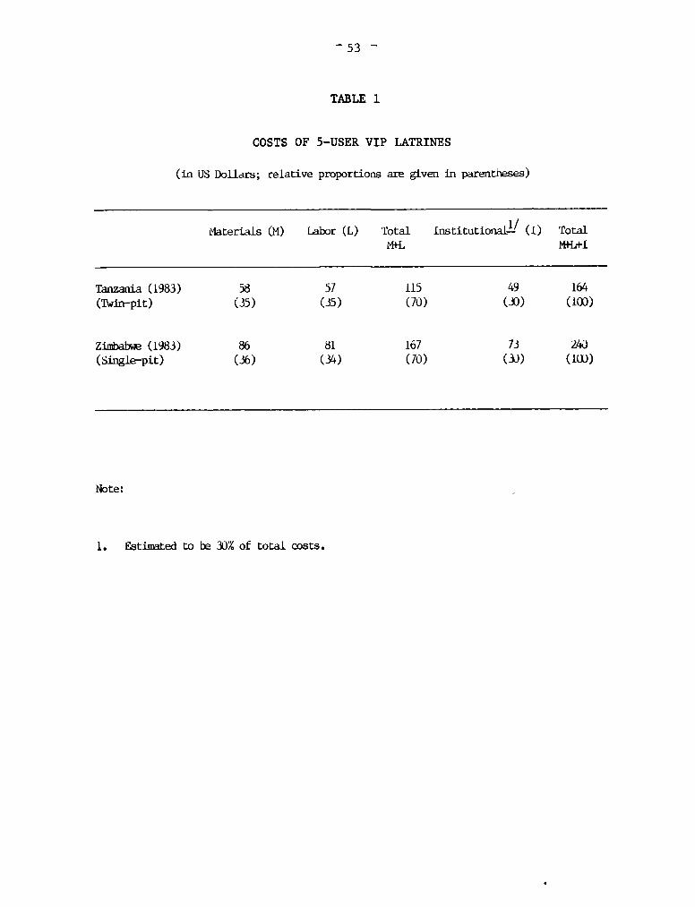
80. One major component of sanitation project costs which is oftenomitted in cost analysis is institutional and project delivery cost. Thisincludes the cost of such activities as community mobilization anddevelopment, information dissemination, training and financial delivery; italso includes monitoring and evaluation and technology delivery activitiessuch as logistic support and engineering supervision. The institutional andproject delivery cost may constitute 15 to 50% of the total cost of asanitation project. It is therefore an important cost component, and it mustnot be ignored. In the absence of adequate information, the institutional anddelivery cost may be assumed to be 30% of the total cost of a project, orabout 45% of the sum of material and labor costs.
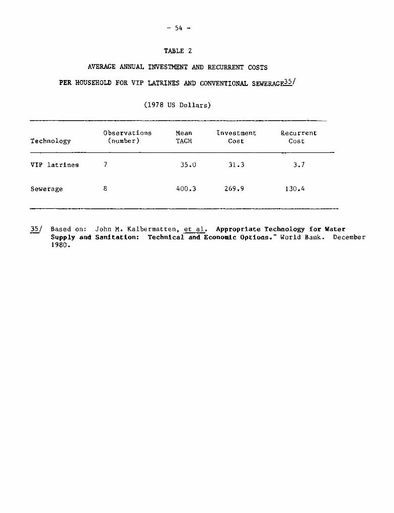
81. Table 1 gives investment costs of five—user VIP latrines from twocountries. Excluding institutional costs, the range of cost is from US$115 toUS$167. The cost range becomes US$164 to US$240 when institutional costs areestimated and included. A breakdown of material and labor costs is given inAnnex III for rural and urban VIP latrines in Zimbabwe. The costs are seen torange from US$70 to US$245 depending upon the nature of the settlement (ruralor urban), soil stability and choice of construction materials. The cost ofVIP latrines relative to the cost of conventional sewerage varies from onecountry to another. In a recent World Bank study, the mean value of the totalannual cost per household (TACH) for sewerage was found to be about 13 timeshigher that it was for the VIP latrine, as Table 2 shows. However, inBotswana the TACH of conventional sewerage was found to be only two and a halftimes the TACH of the VIP latrine. It may be noted that the TACH for seweragein Botswana was found to be the lowest of eight sewerage systems studied inthe World Bank research project; the highest value of TACH, $641.30, was foundin Kyoto, Japan, compared to $142.2 found in Gaborone, Botswana.
_53 —
TABLE 1
COSTS OF 5—USERVIP LATRINES
(in US Dollars; relative proportions are given in parentneses)
MateriaLs (M) Labor (L) Totalr4+L
lnstitutional-~! (1) Totalr41-L+I
Tanzania(1983) 58 57 115 49 164(1\~in—pit) (35) (35) (70) (33) (103)
Zii~ab~(1983) 86 81 167 73 240(Single—pit) (36) (34) (70) (33) (103)
Note:
1 • Estim~tedto be 30% of total costs.
— 54 —
2
AVERÂGEANNUAL INVESTMENT AND RECURRENT COSTS
PER HOUSEHOLDFOR VIP LATRINES AND CONVENTIONALSEWERAGE~’
(1978 US Dollars)
Observations Mean Investment RecurrentTechnology (number) TACH Cost Cost
VIP latrines 7 35.0 31.3 3.7
Sewerage 8 400.3 269.9 130.4
35/ Based on: John M. Kalbermatten, et al. Appropriate Technology for WaterSupply and Sanitation: Technical and Economie Options.~ World Bank. December1980.
— 55 —
TAG/TN/13 ANNEX 1Page 1
SOIL STABILITY CRITERIA
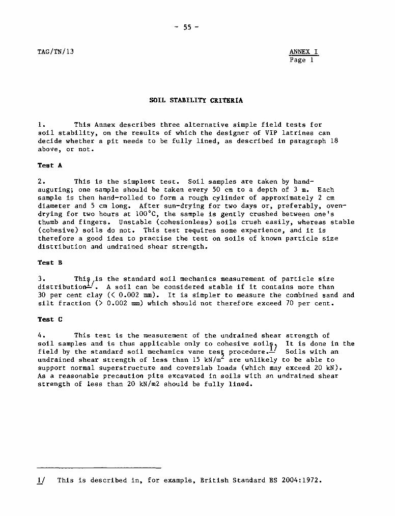
1. This Annex describes three alternative simple field tests forsoil stability, on the results of which the designer of VIP latrines candecide whether a pit needs to be fully lined, as described in paragraph 18above, or not.
Test A
2. This is the simplest test. Soil samples are taken by hand—auguring; one sample should be taken every 50 cm to a depth of 3 m. Eachsample is then haPd—rolled to form a rough cylinder of approximately 2 cmdiameter and 5 cm long. After sun—drying for two days or, preferably, oven—drying for two hours at 100°C, the sample is gently crushed between one’sthumb and fingers. Unstable (cohesionless) soils crush easily, whereas stable(cohesive) soils do not. This test requires some experience, and it istherefore a good idea to practise the test on soils of known particle sizedistribution and undrained shear strength.
Test B
3. Thi~ is the standard soil mechanics measurement of particle sizedistribution—’. A soil can be considered stable if it contains more than30 per cent day (< 0.002 mm). It is simpler to measure the combined sand andsilt fraction (> 0.002 mm) which should not therefore exceed 70 per cent.
Test C
4. This test is the measurement of the undrained shear strength ofsoil samples and is thus applicable only to cohesive soilp It is done in thefield by the standard soil mechanics vane tes~ procedure.—’ Soils with anundrained shear strength of less than 15 kN/m are unlikely to be able tosupport normal superstructure and coverslab loads (which may exceed 20 kN).As a reasonable precaution pits excavated in soils with an undrained shearstrength of less than 20 kN/m2 should be fully lined.
1/ This is described in, for example, British Standard BS 2004:1972.
TAG/TN/l3 —56 —
ANNEX II
Page 1
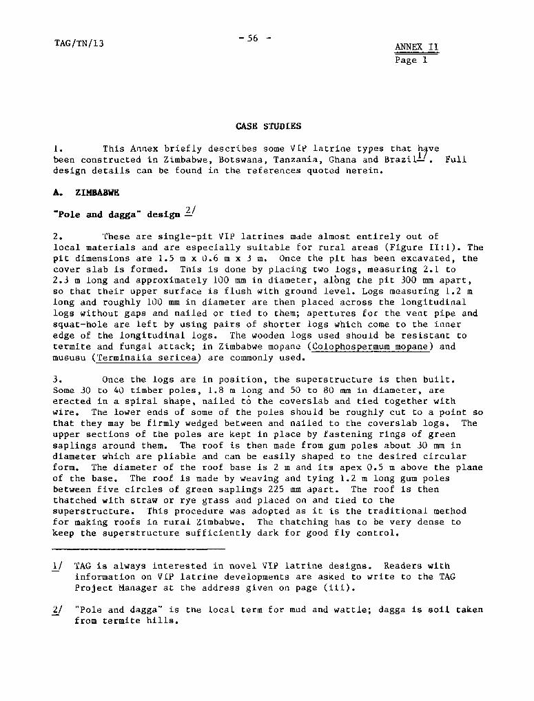
CASE STUDIES
1. This Annex briefly describes some VIP latrine types that h,vebeen constructed in Zimbabwe, Botswana, Tanzania, Ghana and Fulldesign details can be found in the references quoted herein.
A. ZIMBABWE
Pole and daggC design
2. These are single—pit VIP latrines made almost entirely out oflocal materials and are especially suitable for rural areas (Figure II:!). Thepit dimensions are 1.5 m x 0.6 m x 3 m. Once the pit has been excavated, thecover slab is formed. This is done by placing two logs, measuring 2.1 to2.3 m long and approximately 100 mm in diameter, albng the pit 300 mm apart,50 that their upper surface is flush with ground level. Logs measuring 1.2 mlong and roughly 100 mm in diameter are then placed across the longitudinallogs without gaps and nailed or tied to them; apertures for the vent pipe andsquat—hole are left by using pairs of shorter logs which come to the inneredge of the longitudinal logs. The wooden logs used should be resistant totermite and fungal attack; in Zimbabwe mopane (Colophospermum mopane) andmususu (Terminalia sericea) are commonly used.
3. Once the logs are in position, the superstructure is then built.Some 30 to 40 timber poles, 1.8 m long and 50 to 80 mm in diameter, areerected in a spiral shape, nailed t~the coverslab and tied together withwire. The lower ends of some of the poles should be roughly cut to a point 50
that they may be firmly wedged between and nailed to the coverslab logs. Theupper sections of the poles are kept in place by fastening rings of greensaplings around them. The roof is then made from gum poles about 30 mm indiameter which are pliable and can be easily shaped to the desired circularform. The diameter of the roof base Is 2 m and its apex 0.5 m above the planeof the base. The roof is made by weaving and tying 1.2 m long gum polesbetween five circles of green saplings 225 mm apart. The roof is thenthatched with straw or rye grass and placed on and tied to thesuperstructure. This procedure was adopted as it is the traditional methodfor making roof s in rural Zimbabwe. The thatching has to be very dense tokeep the superstructure sufficiently dark for good fly control.
11 TAG is always interested in novel VIP latrine designs. Readers withinformation on VIP latrine developments are asked to write to the TAGProject Manager at the address given on page (iii).
2/ “Pole and dagga” is the local term for mud and wattle; dagga Is soil takenfrom termite hills.
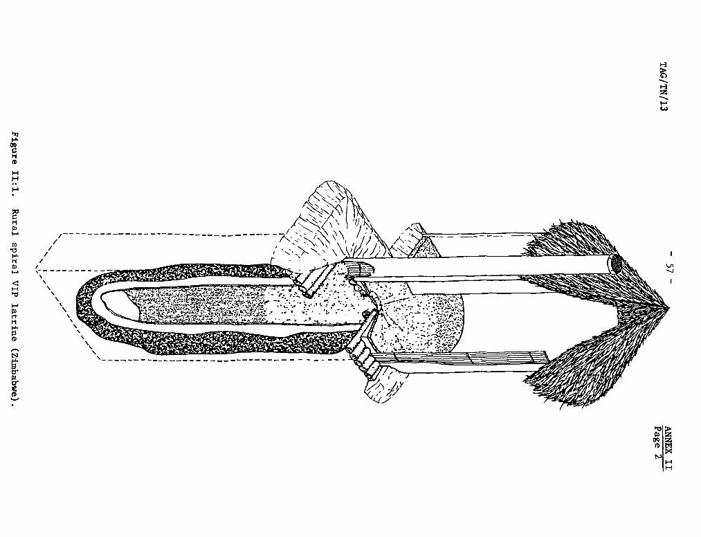
(J~/
/II /03 /
H
03rP‘11-’•
(0
(0
‘-3
031OQI(DI
/ — ———/
TAG/TN/13 — 58 — ANNEX IIPage 3
4. Once ti-te superstructure and roof is complete the application ofmud begins; in Zimbabwe traditional practice in the rural areas is not to usesoil from the ground but from termite huis, as this is found to have betteradhesive properties and greater durability. The superstructure is firstplastered wlth mud, both inside and outside. The coverslab is tnen alsoplastered with mud so that the floor siopes in all directions to the squat—hole. As the mud dries, cracks appear and the surfaces are piastered with mudagain to f111 these cracks and to provide increased strength. The mud isallowed to dry Out and all surfaces are then plastered with a thin coat ofcement mortar (1 part cement, 6 parts sand). The coverslab is then paintedwith black bitumastlc paint.
5. The vent pipe is constructed from a 2.4 m x 0.9 m mat of localreeds woven with string or wire. The mat is rolled up around four or five280 mm diameter rings of green saplings to form a vent pipe of approximately280 mm internal diameter, and the flyscreen is wired on the one end. The ventplpe is then plastered around half its clrcumference with cement mortar; whenthis has dried it is placed in position and tied to the superstructure, andthen the rest of the vent pipe is plastered.
6. Finally, the exposed parts of the coverslab are covered with soilwhich is placed so as to slope gradually away from the latrine to thesurrounding ground level. Grass is then planted to provide protection againstthe ram.
Reference: P.R. Morgan and D.D. Mara, Ventilated Iiiproved Pit Latrines:Recent Developmeats in Zimbabwe, TAG Working Paper No. 2. The World Bank,1982.
Brick design
7. These are also single—pit VIP latrines, but made with morepermanent bulldlng materials (Figure 11:2) The pit dimensions are 1.2 mdiameter x 3 m depth; in stable soils the pit is lined with cement mortar(1 part cement, 8 parts sand), or in open—joint brlckworic in unstable soils.A circular collar of bricks is laid in cement mortar around the pitcircumference at ground level. The reinforced concrete coverslab (1.5 mdiameter x 50 mm thick) is then mortared on to the brick collar.
8. The superstructure is built in a round or “square” spiral shapeto a height of 1.8 m. Only part of the superstructure is over the pit;this is done so that there is sufficient space inside to enable “bucketshowers” to be taken. The part of the superstructure built on the surroundingground is supported on a foundation of a single course of bricks laid incement mortar at right angles to the superstructure. The inside of thesuperstructure is plastered with cement mortar to give a smooth finish.
9. The roof is made from either thatch or ferrocement. Once it isin place and a brick step (to keep out rainwater) has been made at the latrineentrance, soil is used to raise the level of the exposed ground within the
‘1
(0
H
//
//
/
‘-3
03
(btTi
‘-t‘-t
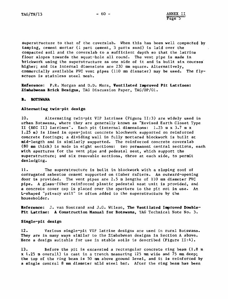
TAG/TN/13 — 60 — ANNEX IIPage 5
superstructure to that of the coverslab. When this has been well compacted bytamping, cement mortar (1 part cement, 3 parts sand) is lald over thecompacted soil and the coverslab to a sufficient depth so that the latrinefloor slopes towards the squat—hole all round. The vent pipe is made inbrickwork using the superstructure as one side of It and is built six courseshigher; and its internal dimensions are 230 mm square. Alternatively,commercially available PVC vent pipes (110 mm diameter) may be used. The fly—sereen Is stainless steel mesh.
Reference: P.R. Morgan and D.D. Mara, Ventilated Improved Pit Latrines:ZimbabweanBrick Designs, TAG Discussion Paper, TAG/DP/01.
S. BOTSWANA
ilternating twin—pit design
10. Alternating twin—pit VIP latrines (Figure 11:3) are widely used inurban Botswana, where they are generally known as “Revised Earth Closet TypeEI (REC II) latrines”. Each pit (internal dimensions: 1.25 m x 3.7 in x
1.25 m) Es lined in open—joint concrete blockwork supported on reinforcedconcrete footings; a dividing wall in fully mortared blockwork is built atmid—length and is similarly supported. The reinforced concrete coverslab(80 mm thick) is made in eight sections: two permanent central sections, eachwith apertures for the vent pipe and pedestal seat, which support thesuperstructure; and six removable sections, three at each side, to perinitdes ludging.
11. The superstructure is built in blockwork with a sloping roof ofcorrugated asbestos cement supported on timber rafters. An outward—openingdoor is provided. The vent pipes are 2.5 in lengths of 110 mmdiameter PVCpipe. A glass—fiber reinforced plastic pedestal seat unit Is provided, anda concrete cover cap is placed over the aperture to the pit not in use. AnL—shaped “privacy wall” is of ten added to the superstructure by thehouseholder.
Reference: J. van Nostrand and J.G. Wilson, The Ventilated Improved Double—Pit Latrine: A Construction Manual for Botswana, TAG Technical Note No. 3.
Single—pit design
12. Various single—pit VIP latrine designs are used in rural Botswana.They are in many ways similar to the Zimbabwean designs in Section A above.Ilere a design suitable for use in stable soils Is described (Figure 11:4).
13. Bef ore the pit is excavated a rectangular concrete ring beam (1.8 in
x 1.25 in overall) is cast in a trench measuring 125 mmwide and 75 mm deep;the top of the ring beam is 50 mm above ground level, and It is reinforced bya single central 8 mm diameter mild steel bar. After the ring beam has been
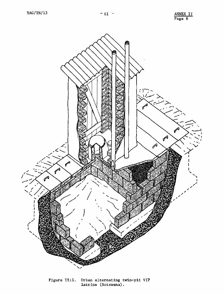
Figure 11:3. Urban alternating twin—pit VIPlatrine (Botswana).
ANNEX IIPage 6
TAG/TN/13— 61 —
—‘
r;.
/ ~
~ /

— 62 —
ANNEX IIPage 7
TAG/TN/13
Figure 11:4. Rural single—pit VIP latrine (Botswana).
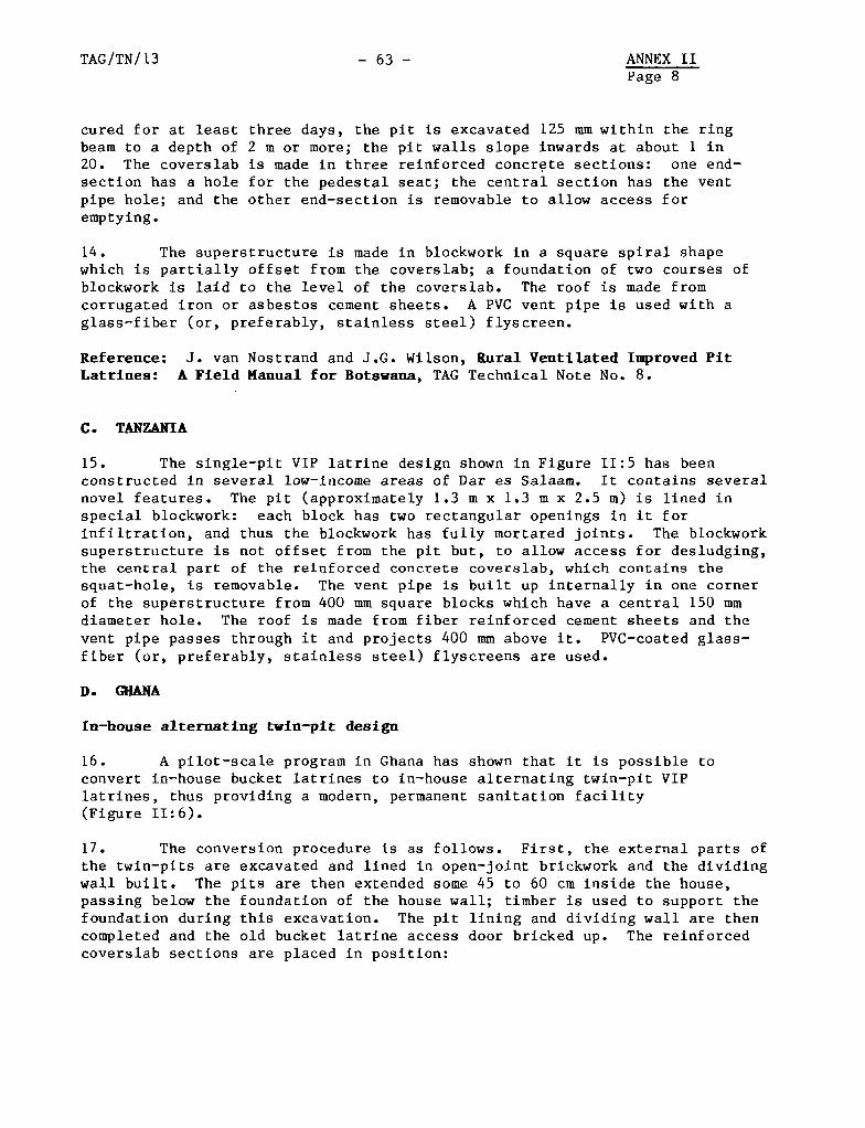
TAG/TN/ 13 - 63 - ANNEX IIPage 8
cured for at least three days, the pit is excavated 125 mmwithin the ringbeam to a depth of 2 in or more; the pit walls slope inwards at about 1 in20. The coverslab is made In three reinforced concrete sections: one end—section has a hole for the pedestal seat; the central section has the ventpipe hole; and the other end—section is removable to allow access foremptying.
14. The superstructure is made in blockwork in a square spiral shapewhich is partially offset from the coverslab; a foundation of two courses ofblockwork Is laid to the level of the coverslab. The roof is made fromcorrugated iron or asbestos cement sheets. A PVC vent pipe Is used with aglass—fiber (or, preferably, stalnless steel) flyscreen.
iteference: J. van Nostrand and J.G. Wlison, Rural Ventilated Improved PitLatrines: A Pield Manual for Botswana, TAG Technical Note No. 8.
C. TANZANIA
15. The single—pit VIP latrlne design shown in Figure 11:5 has beenconstructed In several low—Income areas of Dar es Salaam. It contains severalnovel features. The pit (approxlmately 1.3 in x 1.3 in x 2.5 m) is lined inspecial blockwork: each block has two rectangular openings In It forinfiltratlon, and thus the blockwork has fully mortared jolnts. The blockworksuperstructure Is not offset from the pit but, to aliow access for desludging,the central part of the reinforced concrete coverslab, which contalns thesquat—hole, Is removable. The vent plpe is bullt up Internally in one cornerof the superstructure from 400 mm square blocks which have a central 150 mmdiameter hole. The roof is made from fiber relnforced cement sheets and thevent pipe passes through It and projects 400 mm above it. PVC—coated glass—fiber (or, preferably, staInless steel) flyscreens are used.
D. GHANA
En—house alternating twin—pit design
16. A pilot—scale program in Ghana has shown that It is possible toconvert In—house bucket latrmnes to in—house alternating twin—pit VIPlatrines, thus providlng a modern, permanent sanltation facility(FIgure 11:6).
17. The conversion procedure is as follows. First, the external parts ofthe twin—pits are excavated and lined In open—joint brlckwork and the dividingwall bullt. The pits are then extended some 45 to 60 cm mnside the house,passing below the foundation of the house wall; timber Is used to support thefoundation during this excavatlon. The pit lining and dividing wall are thencompleted and the old bucket latrmne access door brlcked up. The remnforcedcoverslab sections are placed in position:
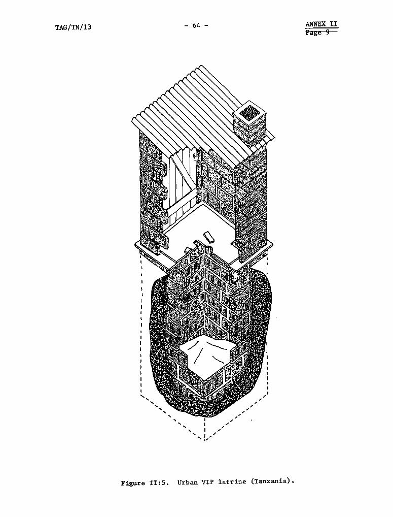
TAG/TN/13 — 64 — ANNEX IIPage 9
Figure 11:5. Urban VIP latrine (Tanzania).
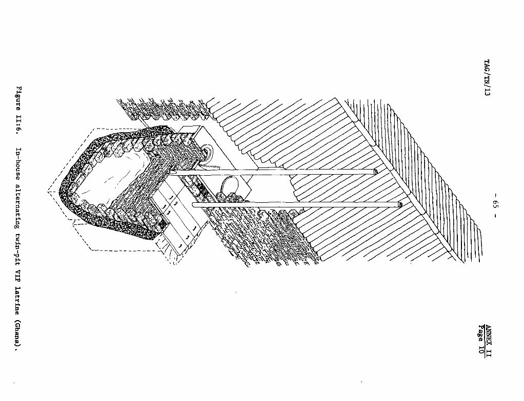
H:7It0
0)(0
0)
rtCDri
rt
OQ
rt
‘-S.
rt
H~0
03(tPl
(0
0It03
/
/
S— —
0’Ln
S
t’
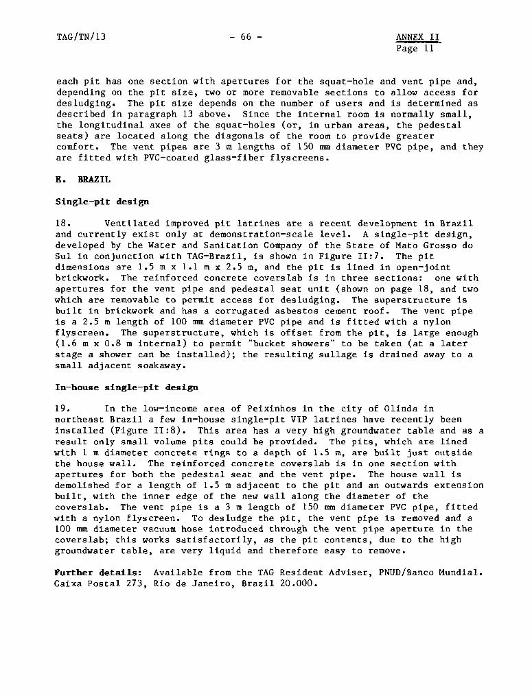
TAG/TN/13 - 66 - ANNEX IIPage 11
each pit has one section with apertures for the squat—hole and vent pipe and,depending on the pit size, two or more removable sections to allow access fordesludging. The pit size depends on the number of users and is determined asdescribed in paragraph 13 above. Since the internal room is normally small,the longitudinal axes of the squat—holes (or, in urban areas, the pedestalseats) are located along the diagonals of the room to provide greatercomfort. The vent pipes are 3 in lengths of 150 mmdiameter PVC pipe, and theyare fitted with PVC—coated glass—fiber flyscreens.
E. BRAZIL
Single—pit design
18. Ventilated improved pit latrines are a recent development in Braziland currently exist only at demonstration—scale level. A single—pit design,developed by the Water and Sanitation Company of the State of Mato Grosso doSul in conjunction with TAG—Brazil, is shown in Figure 11:7. The pitdimensions are 1.5 m x 1.1 m x 2.5 m, and the pit is lined in open—jointbrickwork. The reinforced concrete coverslab is in three sections: one withapertures for the vent pipe and pedestal seat unit (shown on page 18, and twowhich are removable to permit access for desludging. The superstructure isbuilt in brickwork and has a corrugated asbestos cement roof. The vent pipeis a 2.5 m length of 100 mmdiameter PVC pipe and is fitted with a nylonflyscreen. The superstructure, which is offset from the pit, is large enough(1.6 in x 0.8 m internal) to permit “bucket showers” to be taken (at a laterstage a shower can be installed); the resulting sullage is drained away to asmall adjacent soakaway.
In—house single—pit design
19. In the low—income area of Peixinhos in the city of Olinda innortheast Brazil a few in—house single—pit VIP latrines have recently beeninstalled (Figure 11:8). This area has a very high groundwater table and as aresult only small volume pits could be provided. The pits, which are linedwith 1 in diameter concrete rings to a depth of 1.5 m, are built just outsidethe house wall. The reinforced concrete coverslab is in one section withapertures for both the pedestal seat and the vent pipe. The house wall isdemolished for a length of 1.5 m adjacent to the pit and an outwards extensionbuilt, with the inner edge of the new wall along the diameter of thecoverslab. The vent pipe is a 3 m length of 150 mmdiameter PVC pipe, fittedwith a nylon flyscreen. To desludge the pit, the vent pipe is removed and a100 mm diameter vacuum hose introduced through the vent pipe aperture in thecoverslab; this works satisfactorily, as the pit contents, due to the highgroundwater table, are very liquid and therefore easy to remove.
Further details: Available from the TAG Resident Adviser, PNUD/Banco Mundial.Caixa Postal 273, Rio de Janeiro, Brazil 20.000.
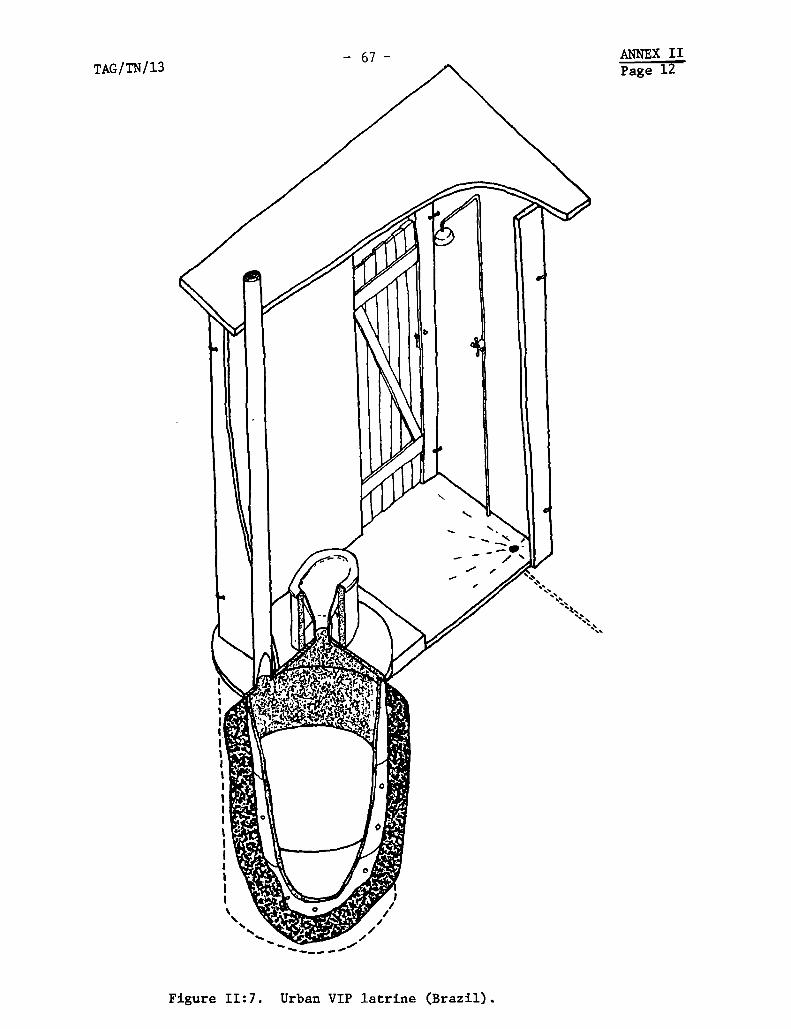
ANNEX IIPage 12TAG/TN/13
— 67 —
//
,/
Figure 11:7. Urban VIP latrine (Brazil).
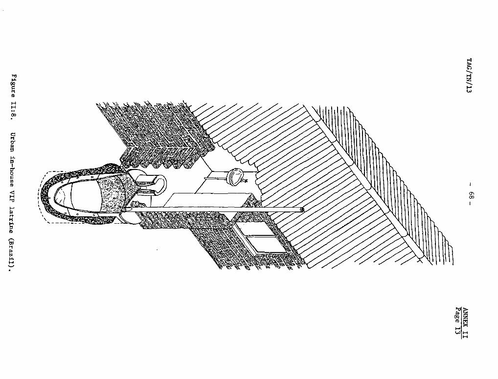
‘-3
0’
03
(D~
‘-t
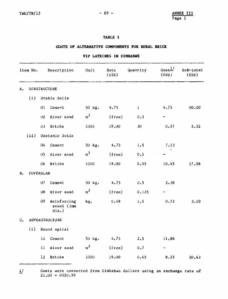
TAG/TN/13 — 69 —
TA8L~ 1
Q~STSOF ALTERNATIV~COMPONENTSFOR RIJRAL BRICK
VIP LATRINES IN ZP(BABIJE
ANNEX IIIPage 1
Item No. DescriptIon Unit Rate Quantity Cost~L’~’ Sub—total(tJS$) (LJS$) (uS$)
A. SLJI3STRIJCTURE
(1) Stable Soils
01 Cement 50 kg. 4.75 1 4.75 00.00
02 River sand in3 (free) 0.3 —
03 Bricks 1000 19.00 30 0.51 5.32
(Ii) Unstable Soils
04 Cement 50 kg. 4.75 1.5 1.13
05 River sand in3 (free) 0.5 —
06 Brlcks 1000 19.00 0.55 10.45 17.58
B. COVERSLAB
07 Cement 50 kg. 4.75 0.5 2.38
08 River sand in3 (free) 0.125
09 Reinforcing kg. 0.48 1.5 0.72 3.10steel (3inmdia.)
C. SUPERSTRUCTURE
(1) Round spiral
10 Cement 50 kg. 4.75 2.5 11.88
11 Rlver sand m3 (free) 0.7 —
12 Bricks 1000 19.00 0.45 8.55 20.43
Costs were converted fromZ1.00 = US$0.95
1/ Zimbabwe dollars using an exchange rate of
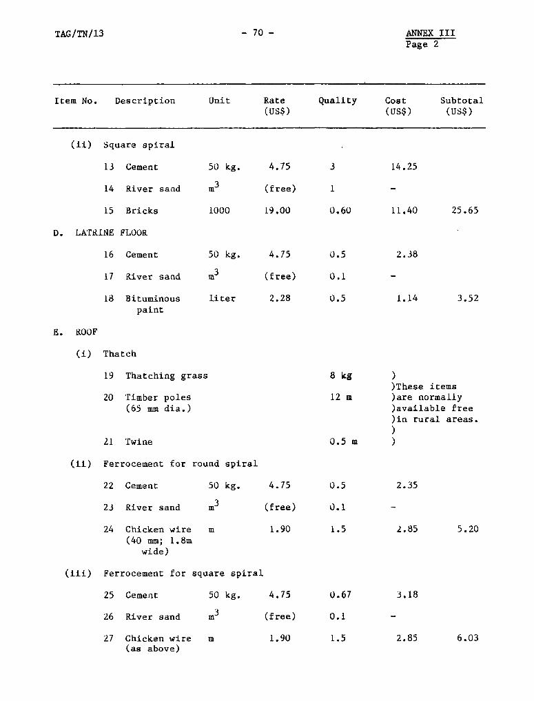
TAG/TN/13 — 70 — ANNEX IIIPage 2
21 Twine
(ii) Ferrocenient for
22 Cement
23 River sand
24 Chicken wire
(40 mm; 1.8wwide)
(iii) Ferrocement for
25 Cement
26 River sand
27 Chicken wire(as above)
round spiral
50 kg.
in
square spiral
50 kg.
Item No. DescrIption Unit Rate Quality Cost Subtotal(US$) (US$) (US$)
50 kg.
En3
1000
50 kg.
liter
(ii) Square splral
13 Cement
14 Rlver saud
15 Bricks
D. LATLUNE FLOOR
16 Cement
17 River sand
18 Bituminouspaint
8. ROOF
Ci) Thatch
19 Thatchlng grass
20 Tiinber poles(65 mm dia.)
4.75
(free)
19.00
4.75
(free)
2.28
4.75
(free)
1.90
4.75
(free)
3
1
O• 60
0.5
0.1
0.5
8 kg
12 in
0.5w )
0.5
O~1
1.5
0.67
0.1
1.5
14.25
11.40 25.65
2.38
1.14 3.52
))These items)are normally)available free)in rural areas.)
2.35
2.85 5.20
3.18
2.85 6.03in 1.90
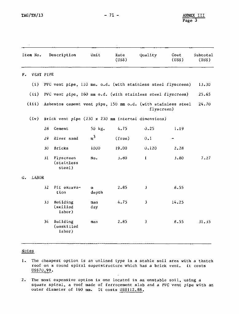
TAG/TN/13 — 71 — ANNEX IIIPage 3
Item No. Descrlption Unit Rate Quality Cost Subtotal(US$) (Us$) (US$)
F. VENT PIPE
(1) PVC vent pipe, 110 mm. o.d. (with stalnless steel flyscreen)
(ii) PVC vent pipe, 160 mm o.d. (with stainless steel flyscreen)
13.30
25.65
(Iii) Asbestos cement vent pipe, 150 mm o.d. (with stainless steelflyscreen)
24.70
(iv) Brick vent pipe (230 x 230 mm internal dimensions)
50 kg.
31 Flyscreen No.
(stairilesssteel)
1. The cheapest option is an unlined type in aroof on a round spiral superstructure whichUS$70.99.
stable soil area with a thatchhas a brick vent. It costs
2. The most expensIve option is one located in an unstable soil, using asquare splral, a roof made of ferrocement slab and a PVC vent pipe wlth anouter diameter of 160 mm. It costs US$112.88.
28 Cement
29 River sand in3
30 8ricks 1000
G. LABOR
4.75 0.25 1.19
(free) 0.1
19.00 0.120 2.28
3.80 1 3.80 7.27
3 8.55
3 14.25
3 8.55 31.35
32 Pit excava— in 2.85don depth
33 Building man 4.75(sKilied day
iabor)
34 BuIlding man 2.85(unskllled
labor)
Notes
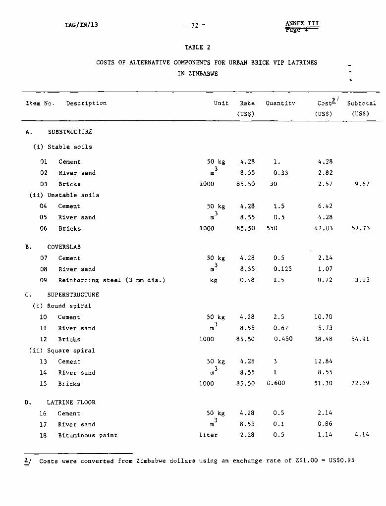
TAG/TN/13 - 72 — ANNEX IIIPage 4
TABLE 2
COSTS OF ALTERNATIVE COMPONENTSFOR IJRBAN BRICK VIP LATRINES
IN ZIMBABWE
Item No- Descript~~n Unit Rate Ouantitv C~st2~’ Subtc’tai
(US~) (tJS$) (US$)
A. SUBSTRUCTURE
Ci) Stable soils
01 Cement 50 kg 4.28 1. 4.28
02 River sand in3 8.55 0.33 2.82
03 Bricks 1000 85.50 30 2.57 9.67
(ii) Unstable soils
04 Cement 50 kg 4.28 1.5 6.42
05 River sand in3 8.55 0.5 4.28
06 Bricks 1000 85.50 550 47.03 57.73
B. COVERSLAB
07 Cement 50 kg 4.28 0.5 2.14
08 River sand m3 8.55 0.125 1.07
09 Reinforcing steel (3 mm dia.) kg 0.48 1.5 0.72 3.93
C. SUPERSTRUCTURE
(1) Round spiral
10 Cement 50 kg 4.28 2.5 10.70
11 River sand in3 8.55 0.67 5.73
12 Bricks 1000 85.50 0.450 38.48 54.91
(ii) Square spiral
13 Cement 50 kg 4.28 3 12.84
14 River sand in3 8.55 1 8.55
15 Bricks 1000 85.50 0.600 51.30 72.69
D. LATRINE FLOOR
16 Cement 50 kg 4.28 0.5 2.14
17 River sand m3 8.55 0.1 0.86
18 Bitutninous paint liter 2.28 0.5 1.14 4.14
2/ Costs were converted from Zimbabwe dollars using art exchange rate of Z$1.00 = US$0.95
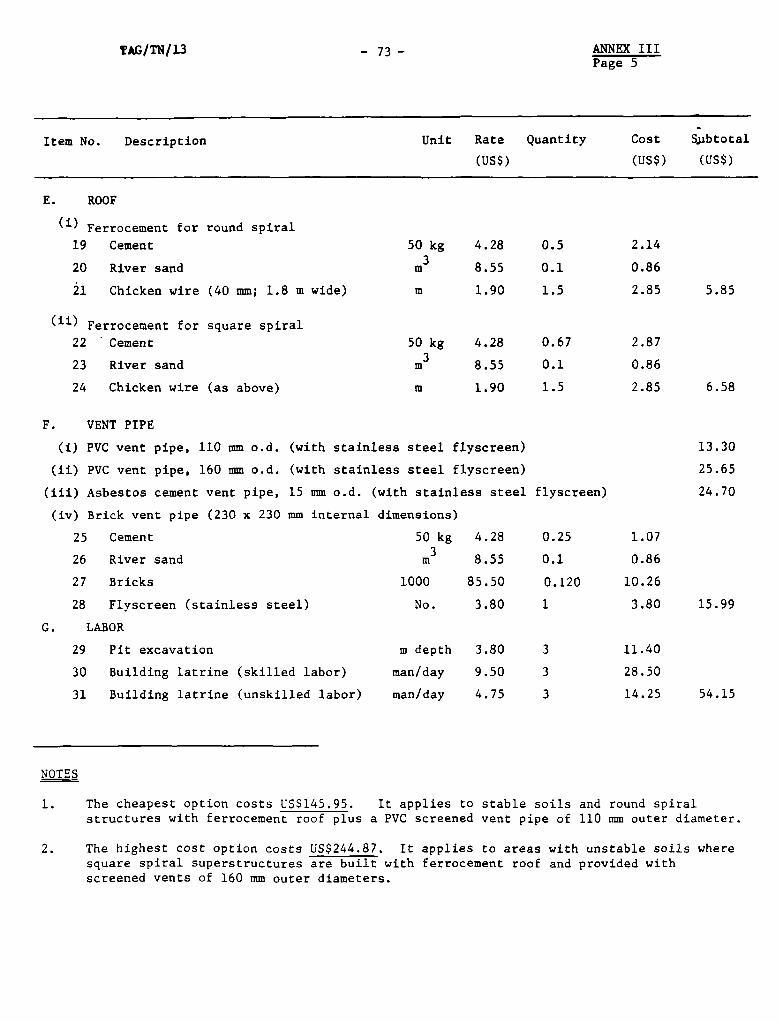
ANNEX IIIPage 5
Item No. Description Unit Rate QuantIty Cost Sj.ibtotal
(US$) (US$) (US$)
E. ROOF
NOTES
1. The cheapest option costs US$145.95. It appiles to stable soils and round spiralstructures with ferrocement roof plus a PVC screened vent pipe of 110 mm outer diameter.
2. The highest oost option costs EJS$244.87. It applies to areas with unstable soils wheresquare spiral superstructures are built with ferrocement roof and provided withscreeried vents of 160 mm outer diameters.
TAG/TN/13 — 73 —
(j) Ferrocement for round spiral
19 Cement 50 kg 4.28 0.5
20 River sand in3 8.55 0.1
21 Chickeri wire (40 tom; 1.8 in wide) in 1.90 1.5
(ii) Ferrocement for square spiral22 Cement 50 kg 4.28 0.67
23 River sand m3 8.55 0.1
24 Chicken wire (as above) in 1.90 1.5
F. VENT PIPE
(1) PVC vent pipe. 110 mm o.d. (with stainless steel flyscreen)
(ii) PVC vent pipe, 160 mm o.d. (with stainless steel flyscreen)
(lii) Asbestos cement vent pipe, 15 mm o.d. (with stainless steel
(iv) Brick vent pipe (230 x 230 mm internal dimenslons)
25 Cement 50 kg 4.28
26 River sand in3 8.55
27 Bricks 1000 85.50
28 Flyscreen (stainless steel) No. 3.80
G. LABOR
2.14
0.86
2.85
2.87
0.86
2.85
1.07
0.86
10.26
3.80
11.40
28.50
14.25
5.85
6.58
13.30
25.65
24.70
15.99
54.15
29 Pit excavation
30 Building latrine (skilled labor)
31 Building latrine (unskllled labor)
f1 y s c reen)
0.25
0.1
0.120
1
3
3
3
in depth
man! day
man! day
3.80
9.50
4.75


LIST OF PUBLIC&TIONS BYTHE TECHNOLOGYADVISORY GROUP (TAG)
UNDP INTERREGIONAL PROJECT INT/81/O47
WP/01 A Model for the Development of a Self—help Water Supply Program;by Colin Glennie.
WP/O2 Ventilated Improved Pit Latrines: Recent Developments in Zimbabwe;by Peter Morgan and D. Duncan Mara.
TN/O1 Methods for Gathering Socio—Cultural Data for Water Supply andSanitation Projects; by Mayling Simpson—Hebert.
TN/O2 Planning of Communication Support (Information, Motivation andEducation) in Sanitation Projects and Programs; by Heli Perrett.
TN/O3 The Ventilated Improved Double—Pit Latrine: A Construction Manualfor Botswana; by John van Nostrand and James G. Wilson.
TN/O4 Pit Latrine Ventilation: Field Investigation Methodology;by Beverley Ryan and D. Duncan Mara.
TN/05 Social Feasibility Analysis of Low—cost Sanitation Projects;by Heli Perrett.
TN/O6 Ventilated Improved Pit Latrines: Vent Pipe Design Guidelines;by Beverley Ryan and D. Duncan Mara.
TN/07 Community—based Workshops for Evaluating and Planning SanitationPrograms: A Case Study of Primary Schools Sanitationin Lesotho; by Piers Cross.
TN/O8 Rural Ventilated Improved Pit Latrines: A Field Manual for Botswana;by John van Nostrand and James G. Wilson.
TN/O9 Handbook for District Sanitation Coordinators; by Kebadire Basaako,Ronald D. Parker, Robert II. Waller and James G. Wilson.
TN/IO Manual on the Design, Construction and Maintenance of Low—costPour—flush Waterseal Latrines in India; by A.K. Roy.
TN/11 Monitoring and Evaluation of Conununication Support Activities inLow—cost Sanitation Projects; by Heli E. Perrett.
TN/12 A Monitoring and Evaluation Manual for Low—cost Sanitation Programsin India; by Ronald Parlato