The Design of Small Bore Sewer Systems
64
TAG Technical Note No. 14 United Nations Development Programme Interregional Project INT/81/047 Executing Agency: World Bank The Design of Small Bore Sewer Systems by Richard J. Otis and D. Duncan Mara, Technology Advisory Group (TAG) 'iogA~~~~~~~~~~~~~~~~~~~~~~~~~~~~~~A Ad~~~~~~~~~~~~~~~~~~~~~~' _ - - B.>t 2W&,s.~~~~~~~~~~ '- IK~~~~~~~~~~~~~~~~ - *1~~~~p b4_ 2 .1 v~~~~~~~~~~~~~~~~~~~~~~~~~~~~~~~~~~~~~~~~~~~1 rF r. - _*,,- . ___2 A joint United Nations Development Programme \> ?and World Bank Contribution to the International Drinking Water Supply and Sanitation Decade Public Disclosure Authorized Public Disclosure Authorized Public Disclosure Authorized Public Disclosure Authorized Public Disclosure Authorized Public Disclosure Authorized Public Disclosure Authorized Public Disclosure Authorized
Transcript of The Design of Small Bore Sewer Systems

TAG Technical Note No. 14
United Nations Development ProgrammeInterregional Project INT/81/047Executing Agency: World Bank
The Design of Small BoreSewer Systems
by Richard J. Otis andD. Duncan Mara,Technology Advisory Group (TAG)
'iogA~~~~~~~~~~~~~~~~~~~~~~~~~~~~~~A
Ad~~~~~~~~~~~~~~~~~~~~~~'
_ - - B.>t 2W&,s.~~~~~~~~~~ '-
IK~~~~~~~~~~~~~~~~
- *1~~~~p
b4_ 2 .1 v~~~~~~~~~~~~~~~~~~~~~~~~~~~~~~~~~~~~~~~~~~~1
rF r. - _*,,- .
___2 A joint United Nations Development Programme\> ?and World Bank Contribution to the International
Drinking Water Supply and Sanitation Decade
Pub
lic D
iscl
osur
e A
utho
rized
Pub
lic D
iscl
osur
e A
utho
rized
Pub
lic D
iscl
osur
e A
utho
rized
Pub
lic D
iscl
osur
e A
utho
rized
Pub
lic D
iscl
osur
e A
utho
rized
Pub
lic D
iscl
osur
e A
utho
rized
Pub
lic D
iscl
osur
e A
utho
rized
Pub
lic D
iscl
osur
e A
utho
rized

LIST OF PUBLICATIONS BY
TtHE TECHWULOGY ADVitSUKY GKOUP YfAG)
UNDP INTERREGIONAL PKOJLCT INT/61/047
WP/UI A Model for Lhe Development of a Self-help Water Supply Program;
by Colin Glennie.
WP/U2 Ventilated improved Pit Latrines: Recent Developments in Zimbabwe;
by Peter Morgan and 0). Duncai i'lara.
TN/0I Mvlethods for Gathering Socio-cultural Data for Water Supply and
Sanitation Projects; by Mlayling Simpson-Hebert.
riN/02 Planning of Communication Support (lnformation, Motivdtion and
Lducatioii) in Sanitationl Projects and Programs; by Heli Perrett.
TN/U3 The Ventilated Improved Double-Pit Latrine: A Construction Manual
for botswana; by John van Nostrand and James G. Wilson.
TN/U4 Pit Latrine Ventilation: Field Investigation Methodology;
by Beverley Kyan and D. Duncan Mara.
TN/05 Social Feasibility Analysis of Low-cost Sanitation Projects;
by hell Perrett.
TN/Ub Ventilated Improved Pit Latrines: Vent Pipe Design Guidelines;
by Bev-:rley Kyan and Z). Duncan Mara.
TN/07 Community-based Workshops for Evaluating and Planning Sanitation
Programs: A Case Study of Primary Schools Sanitauion
in Lesotho; by Piers Cross.
TN/Ub Rurai VentilaLed improved Pit Latrines: A Field Manual for botswana;
by John van Nostrand and James G. Wilson.
i'N/09 t-iandbook tor LstLrict banitatlon CoordLnators; by Kebadire Basaako,
Ronald 1). Parker, Robert B. Waller and James G. Wilson.
'IN/lu Manual on the Design, Construction and Maintenance of Low-cost
Pour-flush Waterseal Latrines in lndia; by A.K. Roy.
TZ/Il Monitoring and Evaluation of CommunicaLlon Support ActivLtles in
Low-cost Sanitation Projects; by Heli E. Perrett.
TIN/i2 A Monitoring and Evaluation Nanual for Low-cost Sanitation Programs
in India; by Ronald Parlato.
TZN/13 Tthe )esign of Ventilated lmproved Pit Latrines; by U. Duncan Mlara.
TN/i4 The Design of Small bore Sewers; by Richard Otis and U. Duncan Mara.
OP/Ut Ventllated lmproved Pit Latrines: Zimbabwean brick Designs;
by Peter R. Morgan and U. Duncan Mara.
DP/I2 A Construction Hanual for Urban Ventilated Improved Pit Latrines:
Examnpies from idnzania; by John van Nostrand, Daniel Makerere
and Kobert boydell.

TAG lbchnical Note No. 14
The Design of Small BoreSewer Systems
by Richard J. Otis andD. Duncan Mara,Technology Advisory Group (TAG)
(,N^. A A joint United Nations Development Programme0*li! and World Bank Contribution to the InternationalDrinking Water Supply and Sanitation Decade
UNITED NATiOS "UI."o

Copyright @ 1985The International Bank for Reconstructionand Development/THE WORLD BANK1818 H Street, NWWashington, DC 20433, U.S.A.
All rights reservedManufactured in the United States of America
First printing May 1985

(i)
PREFACE
This Technical Note by Richard J. Otis and D. Duncan Mara is oneof a series of informal Technical Notes prepared by TAG*/ on variousaspects of water supply and sanitation programs in developing countries.The initial emphasis of TAG was on the promotion of policy shifts fromhigh-cost to low-cost on-site sanitation technologies. This emphasis isnow being directed progressively to a focus on institutional developmentfor on-site low-cost sanitation program delivery.
The present note sets out provisional guidelines for the designof small bore sewers receiving pre-settled domestic wastewater. Theseguidelines are based on recent experience with small bore sewerage inAustralia, Nigeria, the United States of America and Zambia; they have beenwritten particularly for use in developing countries. Consequently,emphasis has been placed upon achieving simplicity of design consistentwith reliability of operation.
The note was originally prepared as an internal discussiondocument. Its wide distribution does not imply endorsement by the sectoragencies,, government, or donor agencies concerned with programs, nor by theWorld Bank or the United Nations Development Programme.
TAG will be interested in receiving comments and suggestions onthe paper, and, in particular, information on costs of technology, deliveryand support systems, and generally, information on experience in programimplementation. All communications should be addressed to the ProjectManager, UNDP Project INT/81/047, Water Supply and Urban DevelopmentDepartment, The World Bank, 1818 H Street, NW. Washington, DC 20433.
Richard N. MiddletonProject Manager
Acknowledgements
The authors would like to express their gratitude to Mr. CecilW. Rose (formerly of the Farmers Home Administration, United StatesDepartment of Agriculture) and Dr. M.G. McGarry (COWATER International,Ottawa, Canada) for their helpful comments on early drafts of thisTechnical Note.
*/ TAG: Technology Advisory Group established under the United NationsDevelopment Programme, UNDP Interregional Project INT/81/047:Development and Implementation of Low-cost Sanitation InvestmentProjects (formerly Global Project GLO/78/006), executed by the WorldBank.


(ii)
TABLE OF CONTENTS
Page
Preface . . .. .. . . .. . . i)
I. INTRODUCTION . . . . . . . ... . . . . . . . . 1
System description . . . . . . . . . . . . .. 1Component parts . . . . . . . . . . . . . . . . . . . . 2Applicability in developing countries . . . . . . . . . 4
II. DESIGN CRITERIA . ... . . . . . . . . . . . . 7
Interceptor tank . . . . . . . . . . . . . . . . . . . 7Small bore sewers and appurtenances . . . . . . . . . . 11
Wastewater treatment options . . . . . . . . . . . . . 17
III. CONSTRUCTION AND MAINTENANCE . . . . . . . . . . . . . . . . 17
Materials . . . . . . . . . . . ... . . . . . . . . . . 17
Construction . . . . . . . . . . . . . . . . . . . . . 19
Maintenance . . . . . . . . . . . . . . . . . . . . . . 22
IV. CASE STUDIES . . . . . . . . . . . . . . . . . . . . . . . . 23
Zambian sewered aqua-privies . . . . . . . . . . . . . 25Australian sewered septic tanks . . . . . . . . . . . . 27
Nigerian sewered aqua-privies . . . . . . . . . . . . . 28
American sewered septic tanks . . . . . . . . . . . . . 29
V. COSTS ................ . 39
ANNEXES
I. Interceptor tank design . . . . . . . . . .. . . . . . 43
II. Small bore sewer design examples . . . . . . . . . . . . 47


Title Page
Table 1 : Unit Cost for Small Bore Sewers. ConventionalSewers. Conventional Sewer and Water MainInstallation from Selected Projects in the UnitedStates of America .................................... 38
Table 2 : Share of Total Project Cost by Component from 10Uniform Grade Small Bore Sewer projects in theUnited States of America ................. **............ 40
Figure 1 : Schematic diagram of a small bore sewer system ........ (iv)
Figure 2 : Typical solids interceptor tank. [The tank may beburied by 300 mm or more to prevent unauthorizedaccess by children or for garbage disposal] ........... 6
Figure 3 : A typical small bore sewer cleanout*....*............. 14
Figure 4 : Individual service connection lift statio n ... ....... 15
Figure 5 : Main in-line lift station with drop inlet. ......... ... 18
Figure 6 : Sewered aqua-privy blocks in the Chipanda area ofMatero, Lusaka, Zambia...... ................... ... 24
Figure 7 : Sewered aqua-privy block in the Chipanda area ofMatero, Lusaka, Zambia. .... ........ ._._. 26
Figure 8 : Sanitation block in New Bussa . . 30
Figure 9 : Sanitation block in New Bussa . . 31
Figure 10 : External view of sanitation block in New Bussa,showing exposed connector sewer and junctionboxes. ................. _ooooo ........ ....... .......... .......... 32
Figure 11 : Site plan of the Mt. Andrew small bore sewers y stem. .o. .ooooooo. o. ... .. .o. o. oo. oo. .ooo. .oooo. . .................. 3 3
Figure 12 : Profile of the 50 mm diameter inflective gradientsmall bore sewer system at Mt. Andrew, Alabama ..... 34
Figure 13 : Site plan of the Westboro small bore seweragesystems ........... o ...o ..o o o.o. ..o..o. ..o ..... .................. 36


'\\ house connection
interceptor tank \\
Figure 1. Schematic diagram of a small bore sewer system


I. INTRODUCTION
System description
1.1 Small bore sewer systems (Figure 1) are designed to receive only
the liquid portion of household wastewater for off-site treatment anddisposal. Grit, grease and other troublesome solids which might cause
obstruction in the sewers are separated from the waste flow in interceptor
tanks installed upstream of every connection to the sewers; the solids which
accumulate in the tanks are removed periodically for safe disposal.
1.2 Collecting only settled wastewater in this manner has fourprincipal advantages:
(a) Reduced water requirements. Since the sewers are not requiredto carry solids, large quantities of water are not needed forsolids transport. Thus, unlike conventional sewers, smallbore sewers can be employed without fear of blockages wheredomestic water consumption is low, where water-saving plumbingfixtures and appliances are widely used, or where long flatruns with few connections are necessary.
(b) Reduced excavation costs. With the troublesome solidsremoved, the sewers do not need to be designed to maintain aminimum flow velocity for self-cleansing. Therefore, ratherthan being installed on a straight path with a uniformgradient, they may be laid with curvilinear alignment with avariable or inflective gradient. This reduces excavationcosts, since the sewer can follow the natural topography moreclosely than conventional sewers and avoid most obstructionswithin its path.
(c) Reduced materials costs. Peak flows which the small boresewers must be designed to handle are lower than thoseexperienced with conventional sewers because the interceptortanks provide some surge storage which attentuates peakflows. Therefore, the sewer and any pumping equipment can be
reduced in size (and pumps handling only liquids aresimpler). In addition, expensive manholes can be replacedwith much less costly cleanouts or flushing points, sincemechanical cleaning equipment is not necessary to maintain thesewers in a free-flowing condition.
(d) Reduced treatment requirements. Screening, grit removal andprimary sedimentation or treatment in anaerobic ponds are notneeded at the treatment works, since these unit processes areperformed in the interceptor tanks.
1.3 Thus, small bore sewer systems provide an economical way to upgrade
existing sanitation facilities to a level of service comparable to
conventional sewers. Because of the lower costs of construction and
maintenance and the ability to function with little water, small bore sewers
can be used where conventional sewerage would be inappropriate. Small bore
sewers therefore offer an opportunity of improving sanitation in areas whichotherwise might not be upgraded.

1.4 The principal disadvantage of the small bore sewer system is the
need for periodic evacuation and disposal of solids from each interceptortank in the system. Experience with the system is limited and mixed.
Consequently, in spite of its obvious advantages it must be used
judiciously and adopted only in situations where there is sufficientprovision to ensure a strong organization for maintenance. Thisorganization must also be able to exercise effective control over
connections to the system. Special precautions should be taken to prevent
illegal connections, since it is likely that interceptor tanks would not be
installed in such connections, thereby introducing solids into a system
which is not designed to handle solids. This could create seriousoperational problems.
Component parts
1.5 Small bore sewer systems consist of: (a) house connections;
(b) interceptor tanks; (c) the sewers and their appurtenances; and (d) a
sewage treatment plant. Occasionally, individual pumping stations may be
required to lift the effluent from the interceptor tank into the sewer to
overcome adverse elevation differences; additionally, pumping stations may
be required in the sewer system itself in very flat areas.
(a) House connection. The house connection is made at the inlet
to the interceptor tank. All household wastes, except for
garbage and trash which must be removed for disposal else-where, enter the system at this point. Storm water must beexcluded,
(b) Interceptor tank. The interceptor tank is a buried water-tight tank with baffled inlet and outlet. It is designed todetain the liquid flow for 12 to 24 hours and to remove bothfloating and settleable solids from the liquid stream.Ample volume is also provided for storage of the solids,which are periodically removed through an access port.Typically, a single-chamber septic tank is used as aninterceptor tank.
(c) Severs. The sewers are small bore plastic pipe (minimumdiameter of 100 mm) which are trenched into the ground at adepth sufficient to collect the settled wastewater from mostconnections by gravity. Unlike conventional sewers, smallbore sewers are not necessarily laid on a uniform gradient
with straight alignment between manholes or cleanouts. Thesewer may have an inflective gradient; that is to say, thesewer may have dips so that sections of it remain full understatic conditions. Also, the alignment may curve to avoidnatural or manmade obstacles. The objective in the designand construction of small bore sewers is to utilize to themaximum extent the energy resulting from the difference inelevation between the upstream and downstream ends.

- 3 -
(d) Cleanouts and manholes. Cleanouts and manholes provideaccess to the sewers for inspection and maintenance. Inmost circumstances, cleanouts are preferable to manholesbecause they cost less and can be more tightly sealed toeliminate most infiltration and grit which commonly enterthrough the lids and walls of manholes. Also, they can beeasily concealed to prevent tampering. They function asflushing points during sewer cleaning operations.
(e) Vents. The sewers must be ventilated to maintainfree-flowing conditions. Vents within the householdplumbing are sufficient, except where inflective gradientsewers are installed. In such cases, the high points of thesewer should be ventilated either by locating the highpoints at connections or by installing a cleanout with aventilated cap.
(f) Lift stations. Lift stations are necessary where elevationdifferences do not permit gravity flow. Either residentialor major lift stations may be used. Residential liftstations are small lift stations pumping wastes from theinterceptor tank of one home or of a small cluster of homesto the sewer, while major lift stations are located in thesewer line and service all connections within a largerdrainage basin. Whenever pumping becomes necessary, thedifference in total annuitized costs between a small boresewer system and conventional sewerage may be greatlyreduced. Consequently, a close cost comparison would berequired between the two before selection between them.
Detailed design criteria for interceptor tanks and the hydraulic design of
small bore sewers and sewer appurtenances are discussed in Section 2below. Design examples are given in Annex II.
1.6 As will be seen from the system description above, the mostimportant characteristic of small bore sewers is that they are designed tohandle only the liquid portion of domestic wastes. Although the term"small bore sewers" has become commonly accepted, it is not in fact a veryaccurate description of the system, since the pipes need not be smalldiameter (the size being determined by hydraulic considerations and notconstrained by other conditions), and the pipe system is not designedaccording to sanitary sewer practice. A more accurate description would be"solids-free sewers", but the best term is probably "effluent drains", asis used in the systems widely employed in Australia; this emphasizes theessential purpose of the sewers - to remove liquid effluents (frominterceptor tanks) that cannot otherwise be disposed of on site - and soforms a natural link to the most likely application of small bore sewers indeveloping countries: to upgrade on-site disposal systems such aspour-flush latrines when changes in water use, housing densities or otherconditions lead to difficulties in on-site effluent disposal. However, forconsistency with other recent publications on this subject, in this note wehave retained the term "small bore sewers".

- 4-
Applicability in developing countries
1.7 Although on-site excreta and sullage1/ disposal systems areusually much less expensive in developing countries than off-sitesystems2 /, there are situations when, due to adverse ground conditions(such as low soil permeability, shallow rock), on-site systems aretechnically infeasible. In such circumstances, off-site disposal isrequired and the full range of off-site disposal technologies has to beevaluated in technical, financial and economic terms. The availableoff-site disposal technologies are:
(a) vault toilets and cartage;(b) conventional sewerage; and(c) small bore sewerage.
1.8 Vault toilets and cartage systems require a high degree oforganizational capability within the institution (usually a municipality)responsible for operating the system: the vault-emptying equipment(commonly a vacuum tanker) has to arrive at each vault very close to thechosen emptying frequency (two to four weeks), otherwise the system fails;and the emptying equipment must be properly maintained. In many developingcountries such a level of institutional competence is lacking and veryoften the system cannot be considered feasible for this reason.
1.9 Conventional sewer systems are so expensive that they areeconomically inappropriate in low-income communities. For example, studiesby the World Bank (see footnote 2) showed that investment costs forconventional sewerage in eight major cities in developing countries rangedfrom US$600 to US$4,000 (at 1978 prices) per household, with correspondingannual economic costs3/ between US$150 and US$650 per household. Suchcosts are clearly unaffordable when it is remembered that total annualhousehold incomes are frequently less than US$500 and often below US$200.
1r10 Small bore sewer systems are especially suitable in developingcountries in the following situations4 /:
(a) Sewered pour-flush toilet systems. When the effluent frompour-flush toilets and household sullage cannot be disposedof on-site, small bore sewerage is almost always the best
1/ Sullage (or "grey water") is all household wastewater other than thewastewater from toilets.
2/ J.M. Kalbermatten, D.S. Julius and C.G. Gunnerson, AppropriateSanitation Alternatives: A Technical and Economic Appraisal, JohnsHopkins University Press, 1982.
3/ These include annuitized investment costs and all operation andmaintenance costs, including the cost of the water used for flushingthe toilet.
4/ The use of small bore sewers is not restricted to developingcountries. As noted in Section IV, they have been successfully usedin Australia and the United States, where they have shown considerablecost savings over conventional systems.

- 5 -
solution5 /; it may be installed in new schemes, or it mayrepresent the last stage in a planned sequence ofincremental sanitation improvements6 /.
(b) Sewered septic tank systems. When existing septic tanksystems have failed, commonly due to the soil becomingunable to absorb increased wastewater flows resulting fromimprovements in the water supply distribution system or fromincreased housing densities, the septic tank effluent isbest discharged into small bore sewers; this is almostalways less expensive than abandoning the septic tanks andinstalling a conventional sewer network. In certaincircumstances, especially in very flat terrain, it may beeconomically advantageous to install sewered septic tanksystems - in conjunction with low-volume cistern-flushtoilets - in new housing schemes as well.
From the perspective of the householder there is little difference betweensmall bore and conventional sewer systems, provided the interceptor tank isdesludged regularly7 /.
1.11 In new schemes small bore sewerage often appears to have littleadvantage over conventional sewerage when compared to the latter in presentworth terms. Yet the distribution of its costs between capital investmentand operation and maintenance is quite different to those of conventionalsystems and is generally more appropriate to developing country conditions:capital costs - with their commonly high foreign exchange requirements -are lower; less skill is required in its construction; and its operationand maintenance are quite different to those of conventional systems and
5/ Sewered pour-flush toilet systems are best used in conjunction with atleast a yard-tap level of water supply service. They may also beappropriate for use with a water supply system based on publicstandpipes; however, this depends on the standpipe density and thewillingness and ability of the householders to carry sufficient waterhome. With sewered pour-flush toilets the total wastewater flow willnormally be low, in the region of 30-80 litres per capita per day.
6/ See J.M. Kalbermatten, D.S. Julius, C.G. Gunnerson and D.D. Mara,Appropriate Sanitation Alternatives: A Planning and DesignManual, Johns Hopkins University Press, 1982. A final in-houseimprovement might be the upgrading of the pour-flush toilet to alow-volume (three to five litres) cistern-flush toilet.
7/ Ideally, this should be the responsibility of the local water supplyand sewerage agency, enabling the cost of desludging to be included asa normal part of the sewerage tariff, and so covered by regular smallmonthly payments rather than forming a large lump sum cost whichhouseholders may be unable or unwilling to afford.

concrete cover slab removable inspection covers
75mm 0 inlet 1 f
S _ t 75mm L L l50mm 0 outlet
150mm 150mm1Ml I brick or
blockworkW W wallsffi C(renderedg g internally)
2 -. . - -reinforced concrete base slab
Figure 2. Typical solids interceptor tank. [The tank may be buried by 300 mm or more toprevent unauthorized access by children or for garbage disposal.]

are more labor-intensive, and these costs (which are generally lower thanthose for conventional systems) can be mainly paid for in local currency'out of revenue. Small bore sewerage is inherently a much more flexiblesystem than conventional sewerage and its feasibility should always beevaluated during the technology selection stage of a feasibility studysince it can offer a viable solution in many situations where conventionalsystems are technically or economically infeasible.
II. DESIGN CRITERIA
Interceptor tank
2.1 Functions. The interceptor tank (Figure 2) is designed toperform four primary functions:
(a) Sedimentation: The foremost function of the interceptortapk is to remove solids suspended in the wastewater. It isdesigned to provide quiescent conditions for a period oftime sufficient to allow the settleable solids to fall tothe bottom, and the floatable solids to rise to the top.Inlet and outlet baffles prevent short-circuiting ofwastewater through the tank and retain the sludge and scumblankets that form.
(b) Storage: To avoid too frequent removal of the accumulatedsolids, the tank is designed with sufficient volume to storesludge and scum for three years or more without disturbingthe sedimentation function.
(c) Digestion: Anaerobic biological digestion of the sludge isa beneficial result of prolonged storage of the solids inthe tank. The bacteria in the tank deplete any oxygen thatmay be dissolved in the waste while feeding on theconcentrated organics. Anaerobic bacteria attack thecomplex organic compounds reducing them to soluble compoundsand gases including H2, C02, NH3, H2 S and CH4. Thisdigestion has several effects on tank performance:
(i) Sludge volume reduction
The sludge volume may be reduced by up to 50-80%(depending on temperature), so reducing sludgepumping frequency.
(ii) Mixing
The rising gas bubbles from the sludge blanket maycarry active organisms with them seeding theliquid clear space providing anaerobicdecomposition of the collodial and soluble organicsolids remaining in the liquid phase.

-8-
(iii) Turbulence
The rising bubbles may re-suspend settled solidsso that they are carried out of the tank.
(iv) Hazardous atmosphere
Toxic, anoxic or explosive atmospheres may resultfrom the accumulation of the gases produced in thetank. This atmosphere can be hazardous to septagepumpers.
(d) Flow attenuation: Interceptor tanks reduce peak flowsubstantially by providing limited surge storage.Reductions from 11 litre/hour to less than 4 litre/hour havebeen reported8/. The attenuation increases as the liquidsurface area of the tank increases.
2.2 Number of households served. In the small bore sewerage schemeswhich have been installed so far in industralized and developing countries(see Section IV) each household is usually served by its own solids
interceptor tank. In many instances this may be the optimal solution, butconsideration should be given to the feasibility of connecting more than
one household to each interceptor tank. This is likely to be a lower-cost
solution in many situations, especially in high-density, low-income urbanareas.
2.3 Design flows. Estimates of household wastewater flows arecommonly based on the household water consumption. Thus wastewater flows
are a function of the level of water supply service (yard taps, multiple
tap in-house connections), the adequacy of the supply (high or low mainspressure, intermittent supplies), the presence or absence of water-savingplumbing fixtures, and socio-economic status (the proportion of waterconsumption used for such purposes as animal or garden watering, car
washing and other non-in-house uses resulting in wastewater not dischargedinto a sanitary drain). Considerable care has therefore to be exercised by
the design engineer in estimating the design flow, as often the factors are
difficult to evaluate precisely; over-estimation of the flow usually
results in the interceptor tank and small bore sewers being overdesigned,and under-estimation results in a system prone to failure. Veryapproximate guidelines for wastewater flows are as follows:
Yard tap supplies: 40 - 80 lcd (litres per caput per day)
Multiple tap in-house supplies: 80 - 120 lcd
8/ University of Wisconsin, Management of Small Waste Water Flows,Publication No. EPA-600/2-78-173, United States EnvironmentalProtection Agency, Cincinnati, Ohio, 1978.

Flows in excess of 120 lcd should not be considered feasible in low-incomecommunities (or indeed middle-income communities) as they indicate a severewastage of water; water-saving plumbing fixtures should be used to restrict
water consumption to the level at which resulting wastewater flows are lessthan 120 lcd. It is all too common, however, for design engineers to
assume wastewater flows of 200 lcd or more; in developing countries this isnormally unjustified (especially in low-income communities) and results inexcessively expensive, and hence unaffordable, solutions.
2.4 Conventional sewer systems are typically designed for an economiclife of about 30 years. Because of their high initial cost and relativeinflexibility once installed, it is natural for their designers to think in
terms of a long economic life and to plan accordingly. (Even where itmight appear advantageous to lay a smaller system initially, and toduplicate it when needed, the disruption caused in high-density areas by
the installation of duplicate mains is such that many city authoritiesprefer to lay the larger-capacity mains in the first instance.) Small bore
sewer systems, in contrast, appear much more suitable for upgrading instages, either by duplication of the mains or by installing relativelysimple pumping equipment; so the design should examine the relativeeconomic costs of laying systems with initial capacities sufficient to
carry the flows expected to arise in, say, 10, 20, or 30 years, withappropriate upgrading at the end of each stage. (The discountingtechniques used in comparing these alternative development sequences arenot covered in this Technical Note, but appear in standard works on
engineering economics.) Careful analysis of alternative developmentsequences is especially important in the case of small bore sewers, sincethey are likely to be installed in low- to middle-income areas on theperipheries of towns in developing countries, where very high rates ofurban population growth will probably result in considerable changes insettlement patterns and in provision of water supply service during thedesign period.
2.5 Volume. The interceptor tank must have sufficient volume toprovide an adequate hydraulic detention time for good settling at theestimated daily flow, while reserving a portion of the total volume for
sludge and scum storage. Hydraulic detention times typically range from 12
to 24 hours. The volume reserved for sludge and scum storage depends onseveral factors, including the total solids which reach the tank daily, the
ambient temperature and the frequency of solids removal. Guidelines(generally based on septic tank design procedures) have been developed todetermine the necessary volume of the interceptor tank for a givenapplication. Design guidelines are reviewed in Annex I.
2.6 Geometry. The preferred shape of interceptor tank is rectangular
with a length to breadth ratio of 2 to 1, or higher, in order to reduceshort-circuiting of the raw wastewater across the tank, and so improvesuspended solids removal.

- 10 -
2.7 For equal volumes, shallow tanks are preferred to deep tanks,
since they provide more hydraulic surge storage capacity and greaterreduction of the velocity of the outflow, and so improve solids retention.Also, the depth of excavation is reduced, thus lowering costs and lessening
problems with groundwater infiltration. However, to ensure good removal of
settleable solids, the liquid depth of the tank should be at least 0.9 m
but not more than 2 m.
2.8 Single-compartment interceptor tanks are sufficient to remove
settleable solids, since the suspended solids carried out in the effluent
are not likely to settle in the sewer.
2.9 Inlets and outlets. The inlet to the tank should be equal in
size or larger than the incoming building sewer to prevent blockages at the
inlet. To prevent blockages in the small bore sewers, the tank outlet
should be smaller than or equal to the diameter of the sewer. Both inlet
and outlet connections should be watertight.
2.10 Baffles should be provided at both inlet and outlet. Inlet
baffles are designed to dissipate the energy of the influent and deflect it
downward into the tank. This prevents short-circuiting of the liquid
across the top of the tank to the outlet and mixes the fresh waste with thebiologically active liquid and sludge in the tank. The outlet baffle is
designed to retain the scum layer within the tank. Sanitary tees are
commonly used but semi-circular baffles are equally effective. The baffleshould extend 150 mm above the liquid level to rise above the scum layer,
and down to approximately 30 to 40% of the liquid depth. A curtain, or
hanging, baffle is not recommended on the inlet because scum is able to
build up behind it and so plug the inlet.
2.11 The outlet invert should be at a sufficient level below that of
the inlet to provide some surge storage and prevent stranding of solids in
the building sewer during momentary rises in the liquid level when waste-
water enters the tank. A drop of 75 mm is recommended. A minimum free-
board or space above the liquid level of 300 mm should be provided for scum
storage and ventilation.
2.12 Ventilation. A free flow of air must be provided between the
house plumbing and the small bore sewer. Therefore, the inlet and outletbaffles should be open above the scum layer.
2.13 Access. Manholes must be provided in each interceptor tank for
removal of the accumulated sludge and scum. A hole 300 to 600 mm across is
common. In large tanks, more than one manhole may be necessary. The
manholes are often buried to prevent accidental entry or odor problems. An
inspection port above the inlet and outlet must also be provided. This
allows inspection of sludge and scum levels to determine when desludging is
necessary and to allow cleaning of the baffle if it should become fouled.
2.14 Structural design. Structural considerations should include soil
loading, hydrostatic loading and vehicular loading. Soil loadings must
always be considered for the tank walls, floor and cover. In areas of
- 11 -
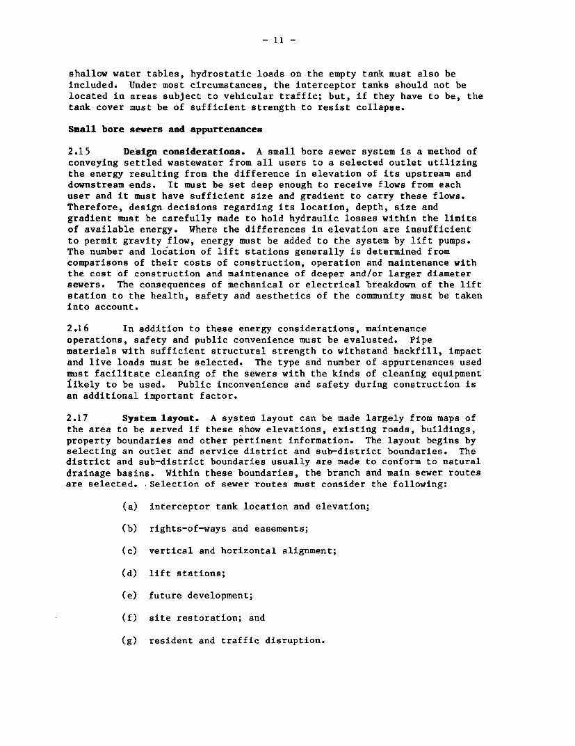
shallow water tables, hydrostatic loads on the empty tank must also beincluded. Under most circumstances, the interceptor tanks should not belocated in areas subject to vehicular traffic; but, if they have to be, thetank cover must be of sufficient strength to resist collapse.
Small bore severs and appurtenances
2.15 Design considerations. A small bore sewer system is a method ofconveying settled wastewater from all users to a selected outlet utilizingthe energy resulting from the difference in elevation of its upstream anddownstream ends. It must be set deep enough to receive flows from eachuser and it must have sufficient size and gradient to carry these flows.Therefore, design decisions regarding its location, depth, size andgradient must be carefully made to hold hydraulic losses within the limitsof available energy. Where the differences in elevation are insufficientto permit gravity flow, energy must be added to the system by lift pumps.The number and location of lift stations generally is determined fromcomparisons of their costs of construction, operation and maintenance withthe cost of construction and maintenance of deeper and/or larger diametersewers. The consequences of mechanical or electrical breakdown of the liftstation to the health, safety and aesthetics of the community must be takeninto account.
2.16 In addition to these energy considerations, maintenanceoperations, safety and public convenience must be evaluated. Pipematerials with sufficient structural strength to withstand backfill, impactand live loads must be selected. The type and number of appurtenances usedmust facilitate cleaning of the sewers with the kinds of cleaning equipmentiikely to be used. Public inconvenience and safety during construction isan additional important factor.
2.17 System layout. A system layout can be made largely from maps ofthe area to be served if these show elevations, existing roads, buildings,property boundaries and other pertinent information. The layout begins byselecting an outlet and service district and sub-district boundaries. Thedistrict and sub-district boundaries usually are made to conform to naturaldrainage basins. Within these boundaries, the branch and main sewer routesare selected. Selection of sewer routes must consider the following:
(a) interceptor tank location and elevation;
(b) rights-of-ways and easements;
(c) vertical and horizontal alignment;
(d) lift stations;
(e) future development;
(f) site restoration; and
(g) resident and traffic disruption.

- 12 -
The location and outlet elevation of the interceptor tanks together with
the local topography will establish the routes and necessary depths of thesewers in most cases. Use of existing rights-of-way and easements shouldbe assessed but if excavation costs can be reduced significantly by some
other route special easements may be necessary. While it is desirable toserve every connection by gravity, the local terrain or cost of excavationmay require that lift stations be used. Groups of homes can be served by asingle lift station or each home can be served individually. Costconsiderations may dictate which alternative to use, but thought must begiven to the consequences of pump failure; for example, failure ofindividual lift stations disrupt fewer families but many pumps may be moredifficult to maintain. Problems created by overflows should also beconsidered in site selection. The cost of reinstating pavements, curbs andgutters and other structures which may be torn up during construction will
be an important consideration in locating routes. Curvilinear alignmentwill allow some structures to be avoided but this must be carefully plannedso that joint deflections do not exceed those permitted by the pipemanufacturer. Also, if homes are on either side of a roadway,consideration should be given to laying sewers on both sides to avoidexpensive road crossings.
2.18 Peak flow estimation. The wastewater flows which reach the smallbore sewers are attenuated markedly in the interceptor tank from the rate
at which they are discharged by the user. The extent of attenuation is afunction of the tank liquid surface area and the length of time over which
the wastewater is discharged to the tank. For example, a 100 litre bathdischarging for a period of 2 minutes to an interceptor tank with a liquidsurface area of 4.2 m2 resulted in an instantaneous peak flow from the tank
of approximately 16 litres/minute, but within 15 minutes the rate was lessthan 2 litres/minute (see footnote 8, page 8). Outflow will equal inflowonly with prolonged discharges of approximately 15 minutes or more 9 /;however flows of this duration rarely occur, except occasionally fromindustrial or institutional sources.
2.19 There are very few data on the magnitude of peak flows in smallbore sewers. In the system serving 200 people at Westboro, Wisconsin(Section 4.17), peak factors of 1.2 to 1.3 have been observed. Until more
field data are available it seems prudent to adopt a design flow peakfactor of 2.
2.20 Where gravity connections are not possible or economic over thefull design life, pumped discharges are necessary. The discharge rate and
9/ E.E. Jones, Domestic water use in individual homes and hydraulicloading of and discharge from septic tanks, in: Home Sewage Disposal(Publication No. PROC-175), American Society of AgriculturalEngineers, St. Joseph, Michigan, 1975.

- 13 -
duration of each pumping cycle become the important factors in establishingpeak flow rates for these connections. The peak flow rate will equal thepump discharge rate, unless the pumping cycle is less than five minutes.Long pumping should be avoided to prevent excessively surcharged conditionsin the small bore sewers.
2.21 In addition to wastewater flows, estimates of groundwaterinfiltration and surface water inflow must be made. Ideally, the additionof any such "clear" water should be zero, but in practice some imperfectlysealed pipe joints must be expected; these are less common with polyvinylchloride (PVC) pipes, as the joints are easier to make and pipe lengths arelonger than with vitrified clay pipes. If the prevention of clear waterentry cannot be ensured, conservative estimates of clear water inflow wouldbe 20 m3/ha/day for vitrified clay pipes and 10 m3/ha/day for PVC pipes.
2.22 Hydraulic design. Unlike conventional gravity sewers which aredesigned for open channel flow, small bore sewers may be installed withsections depressed below the hydraulic grade line. Thus, flow within asmall bore sewer may alternate between open channel and pressure flow. Inmaking design calculations, separate analysis must be made for each sewersection in which the type of flow does not vary and the slope of the gradeline is reasonably uniform. Manning's equation may be used in thisanalysis:
v = (1/n) R2 / 3 S1/2
where v = velocity of flow, m/sn = pipe roughness coefficientR = hydraulic radius, mS = slope of the hydraulic grade line, m/m
To simplify the computations, a nomograph can be used for this equationunder pressure conduit conditions; a hydraulic elements chart is then usedto relate velocity and flow under full conditions to those under partiallyfull conditions.
2.23 The coefficient of pipe roughness is related to the pipematerial, variations in inside dimensions, fitting, alignment and workman-ship. With time, deposits and biological growths will increase the pipewall roughness; therefore the coefficients selected for design shouldreflect the ultimate roughness expected. Values of n range from 0.011 to0.015 but for most pipe materials a value of 0.013 is suitable.
2.24 Minimum pipe diameters of 50 and 100 mm have been used success-fully in experimental small bore sewers in the United States of America(see Section IV). Selection of the minimum permissible size should bebased primarily on maintenance considerations and costs. At present, inorder to facilitate cleaning of the sewer, a minimum diameter of 100 mm isrecommended in developing countries where the specialized equipment forcleaning smaller pipes is not generally available.

threaded cap
4:-
equal y-branch
Figure 3. A typical small bore sewer cleanout.

- 15 -
control box 4with alarm at house
2 nonreturn valve
-…-- - - -_- - - alarm
pump on
f loat
-: -…- y.~........... pump off
electric submersible pump
Figure 4. Individual service connection lift station.

- 16 -
2.25 Maintenance of strict sewer gradients to ensure that minimum
self-cleansing velocities are achieved daily is not necessary, since small
bore sewers are designed to collect only the liquid portion of the waste-
water. However, the design must ensure that an overall fall does exist
across the system and that the hydraulic grade line during estimated peak
flows does not rise above the outlet invert of any interceptor tank. High
points where the flow changes from pressure flow to open channel flow and
points at the end of long flat sections are critical locations where the
maximum elevation must be established above which the sewer pipe cannot
rise. Between these critical points, the sewer may be constructed with any
profile as long as the hydraulic gradient remains below all interceptor
tank outlet inverts and no additional high points are created (see the
design examples in Annex II).
2.26 Ventilation is not necessary for satisfactory operation of small
bore sewers if the sewers are laid on a continuous negative gradient.
However, if inflections in the gradient exist creating sections where the
sewer is depressed below the hydraulic grade line, portions of the line
will remain full and air will accumulate at high points. To prevent a loss
of capacity due to air accumulation, a service connection or ventilated
cleanout located at the high point will provide air release.
2.27 Appurtenances. Cleanouts and manholes provide points of access
for cleaning and maintaining the sewers. Since hydraulic flushing is
sufficient to cleanse the lines of accumulated organic solids, cleanoutsare recommended in lieu of manholes, except at major junctions, because the
latter are more costly and are a source of infiltration, inflow and grit.
Cleanouts should be located at all upstream termini, intersections of sewer
lines, major changes in direction, high points, and at intervals of 150 to
200 m in long flat sections. A typical cleanout design is shown in
Figure 3.
2.28 Lift stations are used to overcome adverse elevation conditions
either at individual service connections or to raise collected wastewater
from one drainage basin to another. Lift stations at individualconnections are simple in design with low-head, low-capacity corrosion-
resistant pumps designed to handle water rather than sewage (since solids
have been settled out). The pumps are controlled by mercury float switches
(Figure 4; cf. paras. 3.14-3.17), set for small pumping volumes to prevent
surcharging of the sewers. A high-water alarm switch operated off a
separate circuit should be set approximately 15 cm above the 'pump on'
switch to alert the user of any pump malfunction by a visual and audiblealarm. A sufficient volume between the high-water alarm and the influent
sewer invert should be provided to allow storage of wastewater while the
malfunction is corrected.
2.29 Major lift stations serving a drainage basin are conventional in
design except that large-capacity solids-handling pumps are not necessary.
So small-capacity pumps typically used for clean water can be used, rather
than more costly sewage pumps, since large solids and debris do not gain
entry to the sewers and peak flows are attenuated significantly. However,
because of the septic nature of the wastewater in small bore sewers,
corrosion and odors are major problems. All equipment should be of

- 17 -
nonferrous construction, although ferrous metal pumps can be used if theyremain below the low water level. Concrete should be coated with achemically resistant material. To control odors, drop inlets extendedbelow the low water level to minimize agitation of the liquid are effective(Figure 5); a fresh air vent to the sump should be provided. In the eventof power failure, emergency storage is provided in the lift station itself;a truck-mounted self-priming pump is then used to pump the lift stationcontents directly into the force main through the hose connection shown inFigure 5.
Wastewater treatment options
2.30 Waste stabilization ponds are generally the wastewater treatmentoption of choice in developing countries. Pond design guidelines areavailable in a number of publications10 /. To design a series of ponds totreat small bore sewerage effluent, one can conservatively assume BOD5 andfecal coliform reductions of 60% and 90% respectively in interceptor tanksin warm climates. The wastewater should be discharged into a facultativepond 1l/ and thence into maturation ponds, the size and number of which aredetermined in the normal way by the required quality of the final effluent.
2.31 Land treatment is an alternative option which has been used inthe United States12/. The presettled sewage first enters a storage pond,the retention time of which is equal to the maximum number of consecutivedays that the wastewater is not used for irrigation (e.g., during winterfrosts in the United States). The pond effluent is directed in turn to oneof several (usually two to six) grass plots which are designed for anapplication rate of 13-100 mm per week depending on soil type and takinginto account seepage and evapotranspiration losses. The effluent from thegrass plots is collected and discharged into a local stream.
2.32 Alternatively, under certain circumstances, it may be possible todischarge the effluent from small bore sewers into a conventional sewer andthus be able to treat it at the works receiving the unsettled sewage.
III. CONSTRUCTION AND MAINTENANCE
Materials
3.1 Interceptor tanks. Most commonly in developing countries inter-ceptor tanks are constructed in brick or blockwork on a concrete base, and
10/ For example: J.A. Arthur, Notes on the Design and Operation of WasteStabilization Ponds in Warm Climates of Developing Countries, WorldBank Technical Paper No. 7, The World Bank, Washington D.C., 1983; andD.D. Mara, Sewage Treatment in Hot Climates, John Wiley, London, 1976.
11/ An anaerobic pond is not required as the interceptor tanks fulfillthis function.
12/ U.S. Environmental Protection Agency, Process Design Manual for LandTreatment of Municipal Water, Cincinnati, Ohio, October 1981.

- 18 -
pump controls Qand alarm
/~~~~~~~~~~~arih j oint
hose _ _ _
connectorwith cap gate valve
nonreturn
alarm
B _| |pump on
- ._ _ ipump off
electric submersible pump
Figure 5. Main in-line lift station with drop inlet.

- 19 -
rendered with cement mortar internally. The concrete base should be at
least 100 mm thick and should have light reinforcement to prevent surface
cracking (for example, 6 mm diameter mild steel bars at 150 mm centers in
both directions).
3.2 If available, prefabricated tanks of precast concrete, glass-
fiber-reinforced plastic or thermoplastics may be used. Precast concrete
tanks can be readily made at a central casting yard, and are usually made
in flat or cylindrical sections for ease of transport and subsequent
erection on site.
3.3 Sewers. Thermoplastic pipes, most commonly PVC but also low
density polyethylene, are used for small bore sewers. Their advantages
include light weight, long laying lengths, high impact strength, corrosion
resistance, flexibility and ease of cutting in the field. Elastomeric seal
gasket (rubber ring) or solvent weld joints are used. Both pressure and
non-pressure PVC pipe and fittings are avai'able. Where appropriate,
locally available pipes, such as vitrified clay pipes, may be used.
3.4 Cleanouts and manholes. Cleanouts can be easily made up from
standard PVC pipe fittings (Figure 3) (page 14), or they can be made as
small inspection boxes in cement-rendered brick or blockwork with suitable
benching and airtight covers. Manholes are best made in concrete or
cement-rendered brick or blockwork; standard manhole designs (for
conventional sewer networks) should be used. Covers of manholes should be
sealed to prevent ingress of water into the sewer system.
Construction
(a) Interceptor tanks
3.5 Location. The tanks should be located where they can be reached
easily for routine removal of solids. The tanks should be clear of
vehicular traffic areas unless the cover is adequately reinforced to
withstand live traffic loads.
3.6 Testing. Leakage can be detrimental to the performance of small
bore sewers. Infiltration can add significantly to the volume of liquid
the sewers must carry and reduce the solids retention capacity of the
interceptor tanks. Exfiltration can cause the liquid level in the tank to
fall, permitting the scum layer to enter the outlet tee. To ensure water-
tightness, the tanks should be tested prior to installation by filling with
water. After standing for several hours, the tank should be examined for
leakage and repaired as necessary.
3.7 Inlet and outlet piping. All joints at the tank should use
rubber gaskets or be sealed with a durable, water-tight, flexible material.
3.8 Bedding and backfilling. The tank must be set level on
undisturbed soil at an elevation that allows at least a 2.5% slope in the
building sewer. If over-excavation occurs or the natural soil is soft or
yielding, crushed rock should be used as bedding material. Backfill should
be free of large stones, rubbish, waterlogged or other unsuitable
materials. In the vicinity of the inlet and outlet piping, the backfill
should be placed manually and tamped.

- 20 -
3.9 Flotation collars. If the tanks have to be set in soil that maybe saturated at any time, flotation collars should be used to preventflotation when the tank is desludged.
3.10 Depth of cover. Tanks should be kept shallow to allow easyaccess for pumping. However, a minimum depth of cover of 300 mm isrecommended. If deep tanks must be installed, risers should be placed onall access and inspection ports to bring them up to just below groundlevel. Access and inspection ports may be brought above ground level, butonly if they can be securely sealed.
3.11 Existing tanks. Existing tanks may be used to reduceconstruction costs if they are in good repair. A careful inspection ofeach tank is required. The tanks should be emptied completely and wellventilated before inspection. The inlet and outlet baffles should beinspected and the extent of any corrosion determined. Leaks can bedetected by smoke tests. Any tanks failing the inspection test must berepaired or replaced-.
3.12 Building sever. The building sewer should be a 75 - 100 mmdiameter pipe installed at a uniform negative gradient sufficient totransport fecal solids but not so great as to strand solids in the line.Recommended gradients are 1 in 30 (75 mm pipe) and 1 in' 40 (100 mm pipe).Bends greater than 450 should be provided with a cleanout. Great care mustexercised to ensure that all joints are watertight.
3.13 Service connection. Service connections from the interceptortank to the sewer main should be the same or preferably smaller in diameterthan the sewer main. Connections to the main are usually made with wye ortee fittings. If a high point in the main exists near where the connectionis to be made, an effort should be made to provide the connection at thatpoint to act as an air release.
(b) Lift stations
3.14 Effluent pumps. Centrifugal submersible effluent pumps are most
commonly used with small bore sewer systems. Pumps used at individualconnections should be low-capacity pumps to prevent surcharging of thesewers downstream. All pumps should be of cast iron, bronze and/or plasticconstruction and mounted on three integral support feet or a base.
3.15 Discharge piping. Because of the corrosive nature of the waste-water, only plastic pipe should be used. Quick-disconnect couplings shouldbe provided to allow easy removal of the pump for repairs.
3.16 Level sensors. Mercury level control switches have been found tobe the most trouble-free of the several types of switches readily avail-able. They are mercury contact switches encased in floating polyurethaneballs. Two switches are necessary for single pump applications, one for'pump on' and the other for 'pump off'. A third is recommended as a highwater alarm to signal malfunctions.

- 21 -
3.17 Wiring. The wiring used to connect the pump to the power sourceshould be suitable for direct burial. The pump and high-water alarm mustbe on separate circuits.
(c) Sever installation
3.18 Techniques used for the installation of small bore sewers are thesame as those used in conventional sewer construction except thathorizontal and vertical controls need not be maintained as carefully.Usually, construction begins at the treatment and disposal facility withthe pipe being laid in the upstream direction.
3.19 Preliminary layout. Prior to the start of any work, rights-of-way, work areas, clearing limits and pavement cuts should be laid out toprotect adjacent properties. Access roads, detours and protectivebarricades should be laid out and constructed as required in advance ofconstruction.
3.20 Setting line and grade. The line of the sewer should be set bythe designer to avoid unnecessay construction problems or costs. Stakesset at the surface on an offset from the sewer centerline are sufficient.The maximum elevation of each critical highpoint should be specified. Theprofile of the sewer between highpoints is not critical except that thesewer should not rise above the elevation of the last downstream high-point. A minimum depth of cover of 50 cm should be maintained.
3.21 Excavation. Extreme care is necessary to locate and protectexisting utilities. The owners of any utilities should be contacted beforeexcavation commences. In general, over-excavation is not a criticalconcern and should not be backfilled since uniform negative gradients arenot followed. However, to minimize headlosses and potential solids or gascollection points, the pipe should be laid as uniformly as is reasonable.If it is necessary to fill a trench that has been over-excavated, onlysuitable bedding materials should be used and properly tamped. In manyinstances, the pipe may be joined above ground and laid in the trench.Where assembly must be done in the trench all safety precautions should betaken to protect workers.
3.22 Bedding and backfilling. The sewer pipe must be embedded in wellgraded, compacted bedding material. If the original soil is unsuitable,suitable bedding materials should extend at least 100 mm below the bottomof the pipe to 300 mm above the top of the pipe and across the full widthof the trench13/. Backfill materials should be free from waste,objectionable organic matter, rubbish, boggy or other unsuitable materials.
13/ Bedding requirements are detailed in, for example, Gravity SanitarySewer Design and Construction, Manual of Practice No. FD-5, WaterPollution Control Federation, Washington DC, 1982-

- 22 -
3.23 Marking pipe locations. Care must be taken to ensure that the
exact location of the pipe is known. This can be done by pipeline markers
which relate the pipe to existing permanent above-ground structures, or by
using special color-coded pipe location marking tape, if this is available,
buried 100 to 200 mm below ground level and directly over the sewer. In
countries where electronic instruments are available for tracing metal
utilities below ground, a tracer wire should be buried with the PVC sewer
(since the PVC sewer pipe by itself will not be detected by the
instruments).
Maintenance
3.24 Small bore sewers require very little maintenance. The only
routine maintenance which must be performed is the removal of sludge from
each of the interceptor tanks. Routine flushing of the sewer mains has not
been necessary in any of the systems currently in use. However, periodic
flushing is recommended to insure against blockages.
3.25 Administration. Small bore sewer systems should be operated and
maintained by the local agency (e.g., municipality, local water and
sewerage company) responsible for waterborne sanitation. Its responsibili-
ties should include all sewer appurtenances located on private property as
well as those in the public right-of-way. Easements to any appurtenances
should be obtained from each property owner to allow free access.
3.26 Interceptor tanks. Scheduled maintenance for the tanks is
generally limited to yearly inspection and solids removal when necessary.
If the sludge layer is within 300 mm of the bottom of either the inlet or
outlet baffles, or if the bottom of the scum layer is within 75 mm of the
bottom of the outlet baffle, the tank should be desludged. The sludge
layer can be determined by wrapping a cloth (preferably towelling) on a
stick long enough to reach the bottom of the tank. The stick is pushed to
the bottom of the tank, twirled betwen the hands and held in the tank for
about a minute. When the stick is withdrawn, a distinct black mark is left
on the cloth recording the sludge depth. The scum layer can be checked by
nailing a 75 mm square piece of wood on the bottom of the stick. This is
pushed through the scum layer and slowly moved up and down to locate the
bottom of the scum by feeling the change in resistance. The stick is
marked using a convenient point for reference. With the same stick, the
bottom of the outlet baffle is located and the stick marked again. The
distance between the two marks is the distance between the bottom of the
scum layer and outlet baffle.
3.27 Interceptor tanks are cleaned by pumping the contents to a
truck-mounted tank for hauling to a suitable disposal site. All solids
should be removed, although a small quantity may be left in the tank to act
as a seed for the new sludge. At no time should the tank be entered
because of the danger of toxic gases. Land spreading or discharge to a
treatment plant are the most common methods for sludge disposal.
3.28 Sewer mains. Occasional hydraulic flushing of the sewer mains is
required. This is usually sufficient to remove most solids accumulations.
- 23 -
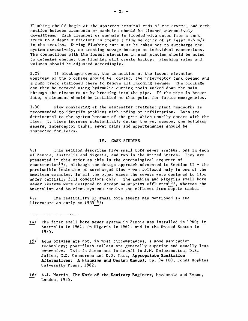
Flushing should begin at the upstream terminal ends of the sewers, and each
section between cleanouts or manholes should be flushed successively
downstream. Each cleanout or manhole is flooded with water from a tank
truck to a depth sufficient to create a flow velocity of at least 0.5 m/s
in the section. During flushing care must be taken not to surcharge the
system excessively, so creating sewage backups at individual connections.
The connections with the lowest elevation in each station should be noted
to detemine whether the flushing will create backup. Flushing rates and
volumes should be adjusted accordingly.
3.29 If blockages occur, the connection at the lowest elevation
upstream of the blockage should be located, the interceptor tank opened and
a pump truck stationed there to remove all incoming sewage. The blockage
can then be removed using hydraulic cutting tools snaked down the main
through the cleanouts or by breaking into the pipe. If the pipe is broken
into, a cleanout should be installed at that point for future emergencies.
3.30 Flow monitoring at the wastewater treatment plant headworks is
recommended to identify problems with inflow or infiltration. Both are
detrimental to the system because of the grit which usually enters with the
flow. If flows increase substantially during the wet season, the building
sewers, interceptor tanks, sewer mains and appurtenances should be
inspected for leaks.
IV. CASE STUDIES
4.1 This section describes five small bore sewer systems, one in each
of Zambia, Australia and Nigeria, and two in the United States. They are
presented in this order as this is the chronological sequence of
construction1 4 /, although the design approach advocated in Section II - the
permissible inclusion of surcharged flow - was followed only in one of the
American examples; in all the other cases the sewers were designed to flow
under partially full conditions only. The Zambian and Nigerian small bore
sewer systems were designed to accept aqua-privy effluents1 5 /, whereas the
Australian and American systems receive the effluent from septic tanks.
4.2 The feasibility of small bore sewers was mentioned in the
literature as early as 193516/:
14/ The first small bore sewer system in Zambia was installed in 1960; in
Australia in 1962; in Nigeria in 1964; and in the United States in
1975.
15/ Aqua-privies are not, in most circumstances, a good sanitation
technology; pour-flush toilets are generally superior and usually less
expensive. This is discussed in detail in J.M. Kalbermatten, D.S.
Julius, C.G. Gunnerson and D.D. Mara, Appropriate Sanitation
Alternatives: A Planning and Design Manual, pp. 94-100, Johns Hopkins
University Press, 1982.
16/ A.J. Martin, The Work of the Sanitary Engineer, Macdonald and Evans,
London, 1935.

- 24 -
lOOmm ¢) outlet to F wash basins with tapssmall bore sewer
squatting plate, 1 itootrests and drop pipeassembly
PLAN
I-
* t..
100mm 0. drop pipes
SECTION
Figure 6. Sewered aqua-privy blocks in the Chipanda area of Matero,Lusaka, Zambia.

- 25 -
"If there is not enough fall to give a
self-cleansing velocity in the main drain, it willsometimes be possible to put in a septic tank at
the head of it. The effluent from a septic tank,being free from any solids capable of choking a
drain, may safely be laid with a merely nominal
fall."
There are, however, no reports of small bore sewers until the Zambian
system was described in 1961.
Zambian severed aqua-privies
4.3 The small bore sewer system was originally developed in the late
1950s by design and research engineers working in the then African Housing
Board of Northern Rhodesia (now the Zambian National Housing Authority)
17a/. Conventional and sullage aqua-privies did not work well in Northern
Rhodesia and so small bore sewers were installed to remove the settled
wastewater (toilet wastes and sullage) from the aqua-privy tanks. They
were originally designed for a minimum daily peak velocity of 0.3 m/s, and
the pipes were 100 mm minimum bore and laid at a minimum gradient of 1 in
200. They were designed only to flow partially full and not, unlike the
more recent North American systems described below, for surcharged flow.
One Zambian system - that at Chipanda in Matero Township, Lusaka - is
described below, but several others exist and are describedelsewhere.17bc/.
4.4 In 1978 there were 532 one- or two-bedroom houses served by the
sewered aqua-privy system in the Chipanda low-income housing area, which
was installed in 1960. Each aqua-privy block serves four contiguous house-
holds, and immediately outside its toilet compartment each household has a
water tap and a sink which discharges its sullage into the aqua-privy tank
(Figures 6 and 7). The tank effluent discharges, via a 100 mm asbestos
cement (AC) connector pipe, into a 150 mm AC lateral sewer which runs
between most of the compounds. This in turn discharges into a 225 mm main
17/ (a) L.J. Vincent, W.E. Algie and G.v.R. Marais, A system of sanitation
for low-cost high-density housing, in: Proceedings of a Symposium on
Hygiene and Sanitation in Relation to Housing, Niamey, 1961, pp.
135-172, Commission for Technical Cooperation in Africa South of the
Sahara, London, 1962.
(b) G-J. W. de Kruijff, Aqua Privy Sewerage Systems: A Survey of Some
Schemes in Zambia, Housing Research and Development Unit, University
of Nairobi, 1978.
(c) R.G. Feachem, D.D. Mara and K.O. Iwugo, Appropriate Sanitation
Technologies for Urban Areas in Africa, Public Utilities Report No.
RES 22, The World Bank, 1979. More detailed information is given in
"Sanitation Site Report No. 4: Zambia (Lusaka and Ndola)", by the
same authors (unpublished World Bank document, May 1978).

I i --
Figure, 7. Seee.qu-rv.lokih Chiand are of MaeoLuskaZmia (Potgrph
Dr. K. lwug o
san,. ~~~~~ +
* v s \ +~*
I
_-
-W
jS'X'
N
r iub_ _
Figure 7. Sewered aqua-privy block in the Chipanda area of Matero, Lusaka, Zambia. (Photograph:Dr. K.O. Iwugo).

- 27 -
sewer, and thence into a 600 mm trunk sewer which transverses the city from
north-west to south-east. The 225 and 600 mm sewers were designed as part
of the conventional sewer system of Lusaka and so receive unsettled
sewage. Some conventional flush-toilets discharge directly into the 150 mm
lateral sewers without settlement. Treatment was originally in a series of
waste stabilization ponds, but these were abandoned when the small bore
sewers were connected to the city's expanded conventional sewerage system.
Australian severed septic tanks 18/
4.5 The State of South Australia has the largest number of small bore
sewer systems receiving septic tank effluent. In South Australia they are
called "common effluent drainage systems" and by mid-1982 65 townships were
served by small bore sewers and 55 extensions to existing schemes had been
added; the total length of small bore sewers was then some 750 km. Demand
for small bore sewerage is high, with 56 townships requiring service over
the next few years. The first small bore sewer scheme, serving 40
properties in Pinnaroo, was installed in 1962. The first township to
provide a scheme for all properties was Barmera; this scheme was
commissioned in 1964 and provided for 493 connections at an average cost of
A$116 (US$129) (1964 prices) per connection. It has five pumping stations
and treatment of the collected wastewater is in a facultative waste
stabilization pond. The design details are as described in paragraph 4.6.
4.6 Design criteria. Small bore sewer schemes are subject to Section
530c of the South Australian Local Government Act 1934-1972 as amended. In
practice schemes have to conform to the specifications laid down by the
South Australian Health Commission (Health Surveying Services division).
The principal design criteria are as follows:
(a) Design velocity and flows: minimum design velocity of 0.46
m/s (1.5 ft/s) at half-full pipe; average wastewater flow of
136 lcd (30 imp. gallon or 36 US gallon per person per day);
peak flow of 0.283 litres/minute per person, which allows
for three times the average dry weather flow.
(b) Pipe diameters and gradients: PVC pipes with diameters of
100, 150 and 200 mm are used; they should not flow more than
half full at any time; and they should be laid at gradients
not flatter than:
18/ Detailed information on Australian small bore sewer systems can be
found in: Common Effluent Drainage Systems, South Australian Health
Commission, Adelaide, 1982. [This publication is a collection under
one cover of various records, directions and legislation on small bore
sewers compiled by the Health Surveying Services office of the South
Australian Health Commission.]

- 28 -
100 mm ........ 0.67% (1 in 150)150 mm ........ 0.40% (1 in 250)200 mm *....o. 0.33% (1 in 300)
(c) Manholes and flushing and inspection points: manholes(minimum diameter 1.066 m, 3.5 ft) should be located atintersections of four sewers (or of two or three sewers ifthe sewer depth exceeds 2.5 m) and every 245 m where minimumgradients are used. Flushing and inspection points shouldbe installed at all changes in direction; at the junction oftwo sewers where the sewer depth is less than 2.5 m; every120 m; at the upstream termini of the scheme; and at eachhousehold connection point. Flushing of the sewers withclean water once a year is recommended.
(d) Cover: the minimum cover is 1 m, unless special arrange-ments are made to prevent damage to the pipe. Recommenda-tions are also made for the design of pumping stations andwaste stabilization ponds (see footnote 18, page 27).
4.7 Nonetheless, the South Australian experience with small boresewers has been excellent and systems installed in the early 1960s areworking very well today, some twenty years later. However, several of theabove design criteria appear too conservative. Smaller pipe diameters, alower peak factor and flatter gradients can be used satisfactorily,especially if the inflective gradient design approach (Section 2.23) isused.
Nigerian sewered aqua-privies 19/
4.8 The only small bore sewerage scheme in Nigeria is the seweredaqua-privy system in the resettlement town of New Bussa near the Kainji Damin Kwara State. This system, which was constructed in 1964, serves 256enclosed family compounds, each housing 15-40 people. A sanitation block,comprisfng a laundry, shower room and an aqua-privy compartment, is
19/ This case study is taken from R.G. Feachem, D.D. Mara and K.O. Iwugo,Appropriate Sanitation Technologies for Urban Areas in Africa,Public Utilities Report RES 22, The World Bank, 1979. More detailedinformation is given in Sanitation Site Report No. 2: New Bussa,Nigeria, by the same authors (unpublished World Bank document, May1978). An early report of the system is given by B.B. Waddy, TheSiting and Sewage System of New Bussa, Journal of the Society ofHealth of Nigeria, 6, pp. 16-19, 1971.

- 29 -
provided in each compound (Figures 8 and 9); a water tap is located in thelaundry area. Sullage is discharged into the aqua-privy tank, which in turndischarges into a short length of 100 mm diameter asbestos cement pipe whichis connected, via a street junction box, to a 100 mm or 150 mm diametercollector sewer which runs in the lane or street outside the compound(Figure 10). The wastewater is treated in one of two single faculativewaste stabilization ponds serving the east and west sides of the town.
4.9 No information on the hydraulic design of the small bore sewers is
available, but it can be reasonably assumed that it was based on the Zambian
schemes described above, as these were the only other schemes in existence
at that time. Some design details differ, however. For example, the shortconnector sewers were commonly exposed, some being protected by a thin layerof concrete (Figure 10); they were thus liable to damage. Many of theprecast concrete junction box covers were broken and it was common to seeexcreta and paper lying in the sewers; some of the junction boxes werecompletely blocked and overflowing. This suggests that the aqua-privy tankswere not being desludged regularly, so permitting solids to enter the smallbore sewers; desludging was expected to be done manually by thehouseholders, with burial of the removed sludge in the compound itself. The
situation was further aggravated by poor tank outlet design: many outletswere broken, so permitting the escape of floating solids.
4.10 In spite of these problems, user satisfaction was generally high,
the main complaints being the intermittence of the water supply and the needfor manual desludging. There were also design faults with the small bore
sewer network, principally the shallow (often zero) depth of the connector
and collector sewers and their junction boxes.
4.11 Total construction costs (household sanitation block, small bore
sewers, ponds) were N£ 33.3 (1964 Nigerian pounds) per household, equivalentto US$408 (1978 dollars).
American severed septic tanks
4.12 There are more than 20 small bore sewer systems in the UnitedStates. The first to be constructed was at Mt. Andrew in Alabama, in 1975.
This system and another at Westboro in Wisconsin, which was constructed in1977, are described below.
(a) Mt. Andrew, Alabama 20/
4.13 This experimental small bore sewer system serves the Grady W.
Taylor subdivision, a self-help housing project for 31 low-income families.
20/ A detailed description of this system can be found in J.D. Simmons,J.0. Newman, C.W. Rose and E.E. Jones, Small-Diameter, Variable Grade,Gravity Severs for Septic Tank Effluent, In: On-Site Sewage Treatment,(Publication 1-82), American Society of Agricultural Engineers, St.
Joseph, Michigan, 1982.

K~). I
F So
SI~ ~ ~~~~~~~~~I
5-~ ~ ~ A
Figure 8. Sanitation block in New Bussa

- 31 -
loO o G. ~ ~ >+Xf ' = _ shower room .l
100 or 150mm 0 ,, -
outlet to j:.small bore l concrete laundry
sewer slab
4 no precast concrete slabs
PLAN
removable asbestoscement squatting
: ~~~plate
100mm 0drop pipe 2.5m3 tank
SECTION
Figure 9. Sanitation block in New Bussa.

,,.~__ *_ -ki
.. :r-a .a _ ,
b | v |;F;- - S 3-w . L i
Figure 10. External view of sanitation block in New Bussa, showing exposed connector sewer and
junction boxes.

- 33 -
I line C
-interceptor tank with gravity flow
interceptor tank with individual lift station
Figure 11. Site plan of the Mt. Andrew small bore sewer system.

5~~~~~~~~~~~~~~~~~~~~~~~~~~~~~~~~~~
10~~~~~~4
0
w
0 50 100 150 200 250 300Length of sewer (m)
Figure 12. Profile of the 50 mm diameter inflective gradient small bore sewer system at Mt Andrew, Alabama

- 35 -
The system was designed to test three low-cost septic tank effluent
collection systems: (a) a small bore sewer with continuous but not uniform
slope; (b) force main connections to a small bore sewer with continuousslope; and (c) a small bore sewer with variable gradient. Final treatment
and disposal were provided by a stabilization pond. The collection lineswere laid out in a conventional manner (Figure 11). Line B and its
continuation, Line D, both 75 mm diameter PVC pipe, have nearly continuousslope but precise grade control was not maintained. The grade was
controlled only to the extent that adequate fall exists from the septic
tanks to the collection line and thence to the pond. Of the 18 homes served
by these two lines, 8 required lift pumps to enter the collection main.
Line C was constructed with continuous slope to its junction with Line D,
but without precise grade control; it is a 50 mm PVC pipe serving three
homes. Line A, a 295 m long 50 mm PVC pipe with 10 connections, was
constructed with an average fall of 2% but at a constant depth rather than
to grade. As a result, there are five inflections between positive and
negative gradients (Figure 12). No manholes or cleanouts were installed in
any of the lines.
4.14 Modified septic tanks installed upstream of each connection
served as interceptor tanks. Each has two compartments; the first is a
1920 litre settling tank, and the second is a liquid storage compartment of
195 litre capacity. The two compartments are hydraulically connected with
six 50 mm diameter PVC "lamella settling tubes" set at 600 from the
horizontal and with their opening 600 mm above the bottom of the first
compartment. The tubes are intended to remove any solids passing through
the settling compartment and to prevent scum from entering the storage
compartment. The outlet from the storage compartment is a 50 mm PVC
vertical standpipe with its opening 300 mm above the floor. This allows for
surge storage above the outlet and a vent for the drain.
4.15 The residents installed the sewers themselves with technical
assistance. The cost of installation in 1975 was about US$ 6.50 per linear
metre. This system has required very little maintenance during its eight
years of operation. Pumping of the interceptor tanks, the only maintenanceperformed on the system, has been more frequent than originally anticipateddue to the small settling compartment volume. Inspection and sampling of
the tanks and lines were performed after 18 months of operation. Samples of
effluents from the interceptor tanks indicated that the solids removal is no
better and is sometimes worse than conventional septic tanks, but that
sludge, scum and large suspended solids are removed effectively. To inspect
the lines, sections of the 50 mm inflective gradient sewer were removed.Only a thin grey residue was found coating the inside walls of the pipe. No
accumulations of heavy solids were observed.
(b) Westboro, Wisconsin 21/
4.16 This system serves a small rural community of approximately 200
persons. It has 85 house connections, and so is a much larger system than
21/ R.J. Otis, An Alternative Public Wastewater Facility for a Small RuralCoyminity, Small Scale Waste Management Project, University of
Wisconsin, Madison, Wisconsin, 1978.

- 36 -
..............
;11
................... .............. :
small bore sewer with manhole
Figure 13. Site plan of the Westboro small bore sewerage systems.

- 37 -
that at Mt. Andrew. The small bore sewers, designed following the South
Australian guidelines (para. 4.6), are used to collect effluent from
interceptor tanks for direct discharge into a common subsurface soil
absorption field without additional treatment (Figure 13)22/. The sewers
are 100 mm diameter PVC pipes laid at a minimum gradient of 0.67%.
Curvilinear alignments in both the horizontal and vertical planes between
adjacent manholes were allowed. Manholes were installed at the upstream
end of each line, at all junctions and at intervals not exceeding 185 m
(spacings greater than the 122 m typically required for conventional sewers
were permitted because of the availability of hydraulic jetting equipment
able to reach more than 60 m). The few homes with basement drains below
the invert elevation of the collector sewers were provided with small
residential lift stations. In addition, three community lift stations were
necessary.
4.17 Each household has an interceptor tank. Existing septic tanks
were used if they were found to be in good condition; if they were not, new
prefabricated 3,785 litre (1,000 US gallon) single-compartment tanks were
installed regardless of home size. The tanks, whether new or existing, and
all other appurtenances, such as the residential lift stations, were
purchased by the Westboro Sanitary District, which retained owership and
responsibility for their maintenance. The costs of power to run the
residential lift stations are paid by those households requiring them.
4.18 Construction costs of the Westboro system were significantly
greater than the Mt. Andrew system, because it is a more conservative
design and self-help labor could not be used. In particular, problems
involving frost damage to sewer lines in past winters led to specifications
requiring that the small bore sewers be buried much deeper than would be
required simply on hydraulic grounds, significantly increasing cost; this
would not be an issue in the great majority of developing countries. The
total cost was US$245,635 in 1977, representing a cost of US$2,890 per
connection and US$42.60 per linear metre.
4.19 The small bore sewers have performed well over the six years
since the system became operational. The only regular maintenance
performed has been pumping of the interceptor tanks. The tanks are
desludged on a staggered three-year cycle, except for those located at the
larger commercial establishments which are desludged annually. No sewer
cleaning has been necessary. Observation of the sewers indicates that they
rarely flow more than one-eighth to one-quarter full. Solids accumulation
in the sewers is primarily due to slime growths which commonly slough from
the pipe wall. However, minor problems have occurred with the system.
Infiltration and inflow have become a severe problem during heavy rains or
snow melt. The sources have not been positively identified but the
individual interceptor tanks are suspected. Covers of two of the 75 new
tanks installed have collapsed because of insufficient reinforcement.
There is a possibility that others are cracked and so allow groundwater to
seep in. Also, the manholes have been found to be a source of grit, stones
and other debris, as well as of clear water inflow; fortunately, these
22/ For design criteria for soil absorption field systems, see U.S.
Environmental Protection Agency, Process Design Manual for Land
Treatment of Municipal Water, October, 1981.

Table 1: Unit Costs for Small Bore Sewers. Conventional Sewer andWater Main Installation from Selected Projectsin the United States of America
INSTALLED PIPE COST PER METRE (1982 $/M)
DEPTH OF COLLECTOR INSTALLATIONUnited States WATER MAIN
0 - 2 M 2 - 4 M 4 - 6 M INSTALLATIONCommunity
Pipe Dia. Per- Pipe Dia. Per- Pipe Dia. Per- Pipe Diametercent cent cent
100 mm 200 mm Savings 100 mm 200 mm Savings 100 mm 200 mm Savings 100 mm 150 mm 200 mm
West Boro, $24.90 - - $29.90 $37.40 20% - - - _ _ _Wisconsin
Badgek, - - - $15.30 $37.20 40% - - - _ _ _South Dakota
South Corning, $38.50 $46.80 18% $52.90 $75.60 31% - - - - _ _New York
New Castle, $28.80 $50.40 43% $36.00 $54.00 33% - - - $25.20 $27.00 $45.00Virginia
Gardner, $13.90 - - $48.70 $86.90 44% $69.60 $86.90 20% - - -
New York

- 39 -
materials have been retained largely within the manholes where they can beremoved easily. Part of the problem with the manholes is damage to thecovers in the course of snow-clearing operations using heavy equipment; thisgain would not arise in most developing country applications. Corrosion isbecoming severe in the three in-line lift stations where ferrous materialswere used. Pump rails, chains and supports for the float switches will soonrequire replacement with non-corrosive materials. Odors have not been aproblem.
V. COSTS
5.1 Compared to conventional sewerage, small bore sewers can besignificantly less costly to construct and operate, and yet provide a similarlevel of service. With primary sedimentation provided upstream of eachconnection to remove troublesome solids before the wastes enter thecollectors, blockages rarely occur. In addition, flows are attenuated,markedly reducing peak to average flow ratios. As a result, design,construction and maintenance standards established for conventional sewerscan be relaxed. For example, without the solids load, small bore sewers neednot be designed for self-cleansing. Pipe gradients can be reduced andsections depressed below the hydraulic grade line. This reduces the depth ofexcavation necessary, but more importantly allows greater constructiontolerances, reducing the level of skill required by the contractor and theextent of site supervision by the client agency. Also, access for mechanicalcleaning equipment is not necessary since hydraulic flushing, if needed, issufficient to keep the drains free-flowing. Therefore, curvilinear alignmentis permitted and manholes can be replaced by simple cleanouts. Materialcosts are also reduced because attenuated peak flows allow smallerminimum permissible pipe diameters and smaller lift stations; moreover,pumping equipment, which handles liquids and not solids, can be simpler.
5.2 In Australia, "effluent drains" are required to be laid in the sameway as conventional sewers with uniform gradients so as to achieve a minimumof 0.5 m/sec flow velocity. Despite this requirement, construction costs arereported to be 25 to 35% less than conventional sewers. The costs ofinterceptor tanks and drain connections are borne by the users. If theprivately borne costs were to be included in the total costs, however, fewsavings, if any, would result. Practice in the United States of America issimilar to that in Australia. Uniform gradients have been required but inmany cases minimum flow velocities have been reduced to 0.3 m/sec. Reportedsavings in construction costs over conventional sewers range from 0% to 50%.In projects where the reported savings were low, the higher costs wereattributed to a high percentage of interceptor tank replacement. Onlyrecently have projects been constructed in the United States where inflectivegradients were allowed. Cost savings in these projects are expected to begreater, but as-constructed data are not yet available.
5.3 Table 1 presents unit costs from several projects in the UnitedStates23 /. These costs are presented as dollars (1982) per metre for
23/ Otis, R.J., Small Diameter Gravity Sewers: An Alternative WastewaterCollection Method for Unsewered Comminities. U.S. EnvironmentalProtection Agency, Cincinnati, Ohio, 1985.

- 40 -
Table 2: Share of Total Project Cost by Componentfrom 10 Uniform Grade Small Bore Sewer projectsin the United States of America
COMPONENT PERCENT OF TOTAL PROJECT COST
In place pipe 29%
Interceptor Tanks 17%
Lift Stations 13%
Service Connections 13%
Street Repair 7%
Street & R.R. Crossings 6%
Residential Lift Stations 3%
Force Main 3%
Site Restoration 3%
Manholes 3%
Cleanouts 1%
Miscellaneous 2%
100%

- 41 -
installing collector mains laid with a uniform gradient at various depths.Comparisons between 100 mm pipe and 200 mm pipe laid at the same depth andgradient show 20% to 44% savings. Total projects savings would be greaterbecause with flatter or inflective gradients, small bore sewers would avoiddeeper placement. If laid similarly to water mains, costs from the projectin New Castle, (Virginia) suggest the savings would exceed 50% overconventional sewers.
5.4 Table 2 summarizes the construction costs by component of the 10United States uniform grade small bore sewers reviewed. The costs areexpressed as a percentage of the total construction costs. This shows thatinterceptor tanks and service connections account for approximately 30% ofthe total construction costs. In-place pipe costs also account forapproximately 30% of the costs. Thus, even greater savings would result thanthose experienced in the United States in cases where interceptor tanksalready exist and where inflective gradient systems are installed.
5.5 Few operation. and maintenance costs data are available. InAustralia, where theie is nearly 25 years of experience, maintenance has beenshown to be required infrequently, simple to perform and relativelyinexpensive when compared to conventional sewerage24 /. Maintenance personnelneed not be highly skilled to perform the general maintenance duties.Reasons for the lower costs are that the system needs little water tofunction because the interceptor tanks remove solids which may causeblockages, the collectors can be laid at shallow depths, making any necessaryrepairs quick and simple to perform, and the pre-treatment provided by theinterceptor tanks can reduce final treatment costs. The most significantmaintenance operation is the regular desludging of the interceptor tanks.Frequency of desludging will depend on tank size and user habits, varyingbetween 1 to 10 years.
5.6 In developing countries, the most economical application for smallbore sewers is likely to be for the upgrading of areas where existinginstallations (septic tanks or pour-flush latrines with leach pits) arefailing or are not functioning properly because of increased water use orurban expansion, rendering inadequate the area available for septic tankdrain fields or on-site disposal of pour-flush effluents and sullage. Inthese circumstances, the septic tanks can be used as interceptor tanks toreduce the costs of installing the small bore sewers. Upgrading existingsanitation facilities in this manner is far more economical than constructingconventional sewers, not only because of the reduced construction costs butalso because small bore sewers are not dependent on a good and reliable watersupply to function properly.
24/ Environmental Protection Authority. Comparison of Sewerage and CommonEffluent Drainage for Country Townships. Report No. 65/79 EastMelbourne, Australia, 1979.


TAG/TN/14 - 43 - ANNEX IPage 1
INTERCEPTOR TANK VOLUME CALCULATIONS
1. Interceptor tanks are usually designed as septic tanks, and arecent review of septic tank design has highlighted the wide variety ofrecommendations made in national codes of practice1 /. In this Annex arational design procedure for interceptor tanks is presented, based on theBrazilian septic tank code2 /.
2. Interceptor tanks are designed to provide space for four separatefunctions:
(a) solids interception;
(b) digestion of settled solids;
(c) storage of digested solids; and
(d) storage of scum.
These functions and their tank volume requirements are discussed in turn.
Solids interception
3. The intercepted solids comprise two fractions: those in the tankinfluent and those which rise up from the sludge layers through flotation bythe gases produced therein. Theoretically temperature affects the rate ofsedimentation by changing the viscosity of the liquid phase, but in practiceits influence is small and usually ignored. However temperature markedlyaffects the rate of anaerobic digestion and hence gas production; thus withincreasing temperatures more solids will rise through flotation. Hydraulicsurges which occur as a result of high peak flows over a short period of timealso cause some of the settled solids to be resuspended. It is because ofthese two factors - solids flotation and hydraulic resuspension - thatretention times in septic tanks are longer than those normally employed inraw sewage sedimentation tanks. Often a minimum mean hydraulic retentiontime of one day is used (rather than six hours at dry weather flow insedimentation tanks), but there is a formula which relates the retention timeto the contributing population and the per capita wastewater flow3/:
1/ J. Pickford, The Design of Septic Tanks and Aqua-Privies, OverseasBuilding Note No. 187, Building Research Establishment, Garston,England, 1980.
2/ Construsao e Instalacao de Fossas Septicas e DisposicAo dos EfluentesFinais, Norma Brasileira Registrada 7229, Associaao Brasileira deNormas Tecnicas, Rio de Janeiro, 1982.
3/ C.M. Fair and J.C. Geyer, Water Supply and Waste Engineering, p. 901,John Wiley, New York, 1954. The formula quoted has been changed fromUS gallons to litres.

TAG/TN/1 4 - 44- ANNEX IPage 2
th = 1.5 - 0.3 log (Pq) (1)
where th = minimum mean hydraulic retention time, daysP = contributing populationq = wastewater flow, lcd
This equation indicates that the required minimum retention time decreases asthe population served or per capita wastewater flow increases; it thus makesinherent allowance for the fact that the magnitude of peak flows decreaseswith increasing flow rates. However, the minimum recommended retention issix hours.
4. The volume required for sedimentation (Vh,m3) is therefore given bythe equation:
Vh = 10-3(Pq)th (2)
Solids digestion and storage
5. Although the digestion of intercepted solids and the storage ofdigested solids are two separate functions of an interceptor tank, it isnecessary to consider them together since currently available field data donot distinguish between them4 /. The literature on septic tanks is full ofreferences to sludge accumulation rates; reported values vary from 25 litresper capita per annum (lca) to greater than 100 lca. A reasonable estimate ofsludge accumulation, based on the average sludge accumulation in 205 Americanseptic tanks, is 0.19 lcd5/, equivalent to an annual storage requirement of70 litres per capita. Thus the combined sludge digestion and storage volume(Vs,m3) is given by:
Vs = 70 x 10-3 PN (3)
Where N equals desired interval between sucessive desludging operations, years.
Storage of Scum
6. Scum storage requirements are often implicitly included in thesolids storage volume, but this is not strictly correct. Scum results fromfats and grease in sullage and from toilet paper. A study of 268 septictanks in the USA indicated that the submerged scum volume (i.e., the volume
4/ Solids digestion is a very temperature-dependent process, and so clearlyless volume is required for digestion at higher temperatures. However,more field results are required before a reliable design relationshipcan be formulated between the digestion rate in interceptor tanks andtemperature.
5/ S.R. Weibel and others, Studies on Household Sewage Disposal Systems,-Part I, Public Health Service, Environmental Health Center, CincinnatiOhio, 1949.

TAG/TN/14 - 45 - ANNEX IPage 3
below the invert of the outlet pipe) rarely exceeds 0.7 cubic metres 6 /.Thus the maximum submerged scum depth (dss, m) is a function of the tanksurface area (A, m2 );
ds = °0.7/A (4)
Clear space depth
7. The clear space depth, which is the minimum acceptable depth of thesolids settling zone just prior to desludging, comprises the submerged scumclear depth and the sludge clear depth. The submerged scum clear depth isthe distance between the underside of the scum layer and the bottom of theoutlet "tee", and should be at least 75 mm7 /. The sludge clear depth is thedistance between the top of the sludge layer and the bottom of the outlet"*tee"; its minimum value (dec. m) is related to the tank surface area asfollows8!:
dsc = 0.82 - 0.26A (5)
subject to a minimum value of 0.3 m 7/. Thus the minimum total clear spacecalculated as (0.075 + dsc) must be compared with the depth required forsedimentation (= Vh/A), and the greater depth chosen.
Design exa ple
8. Design an interceptor tank to pretreat the wastewater from ahousehold of 8 persons who produce 70 lcd of wastewater; the tank is to bedesludged every three years9/. The solution is as follows:
(a) Calculate the minimum mean hydraulic retention time for settleablesolids sedimentation from equation [1]:
th = 1.5 - 0.3 log(Pq)
- 1.5 - 0.3 log(8 x 70) = 0.68 day
6/ T.W. Bendixen, R.E. Thomas, A.A. McMahan and J.B. Coulter, Effect ofFood Waste Grinders on Septic Tanks, Public Health Service, Robert A.Taft Sanitary Engineering Center, Cincinnati, Ohio, 1961.
7/ J.A. Cotteral and D.M. Norris, "Septic Tank Systems", Journal of theSanitary Engineering Division, American Society of Civil Engineers,(95 9SA4), 715, 1969.
8/ R. Laak, "Multi-chamber septic tanks", Journal of the EnvironmentalEngineering Division, American Society of Civil Engineers, 106 (EE3),539, 1980.
9/ In practice, of course, designers would seek to optimize the combinationof tank volume and desludging frequency, so as to produce a least-costsolution. Thus several desludging intervals would normally beconsidered.

TAG/TN/14 - 46 - Page IPage 4
Thus the volume required for sedimentation is given by equation [21 as:
Vh = 10- 3 (Pq)th
- 10-3(8 x 70)0.68 0.39 m3
(b) Calculate the solids digestion and storage volume fromequation [3]:
Vs = 70 x 10-3PN
= 70 x 10-3(8 x 3) = 1.68 m3
(c) Assume a cross-sectional area (A) of 3 m2. Then:
(i) the maximum depth of sludge (Vs/A) is (1.68/3), - 0.56 m;
(ii) the maximum submerged scum depth (d..) is given byequation [4] as (0.7/3), = 0.23 m;
(iii) the minimum sludge clear space is given by equation [51 as[0.82 - (0.26 x 3)], = 0.04 m; this is less than the minimumof 0.3 m which is therefore adopted;
(iv) the total clear space depth is therefore (0.075 + 0.3) m, =
0.375 m; this is greater than (Vh/A), = (0.38/3) = 0.13 m, sothe total clear space is the controlling factor in the design.
(d) The total effective depth is therefore the sum of the sludge depth(0.56 m), the clear space depth (0.375) and the maximum submerged scum depth(0.23 m), i.e. 1165 mm.
(e) Thus suitable overall internal dimensions of the tank would be1 m x 3 m x 1.5 m, as shown in Figure I.1.
1000t 5
SCUM 230
CLEAR SPACE 300 1500
SLUOGE 560
1 3000 1
Figure 1.1. Dimensions of design example interceptor tank.

TAG/TN/14 47 - ANNEX IIPage 1
SMALL BORE SEWER DESIGN EXAMPLES
Example #1
1. A single small bore sewer is to be constructed to serve 20 lots,of which only 10 have been built to date (Figure II.1). Each existing househas a multiple tap in-house level of water supply service. Provision must bemade for the future connection of 10 lots located above the present upstreamterminus of the sewer. The design (peak) flow is 0.025 litre/second perconnection.
2. Solution. Firstly, individual sections of the sewer are selectedfor hydraulic analysis on the basis of isolating sections with relativelyuniform gradients or flows. In this case nine sections were chosen, as shownin Figure II.1.
3. The hydraulic calculations are presented in Table II.1 anddescribed, column by column, below:
Column 1: Station number
Numbers relating to the commencement of each sewer section andstarting-from the downstream terminus of the sewer.
Column 2: Station elevations
The elevation in metres, of each station above a datum (which inthis case is the elevation of Station 1).
Column 3: Distance
The distance, in metres, of each station from Station 1.
Column 4: Elevation difference over section
The difference, in metres, between the elevations (column 2) ofadjacent stations.
Column 5: Length of section
The difference, in metres, between the station distances (column 3)of adjacent stations.
Column 6: Average slope of section
Column 4 divided by column 5 gives the average slope of the sectionin m/m.
Column 7: Number of connections served
The number of lots connected upstream of the downstream station ofthe section.

5- - S
proposed10 extension
serving4-3 L-10 lots
o/ - 4
E _r
Pr eed branch sser ng 20lots
uj2 - - _ _ _ _ _ _ _ _ _
5~~~~~~~~~~~~
2
o 50 100 150 200 250 300Length of sewer (in)
Figure II.1. Sewer profile for design examples

TAG/TN/14 - 49 - ANNEX IIPage 3
Column 8: Design flow
Column 7 multiplied by 0.025 (the design flow in litre/second perlot) gives the flow in the section in litres/second.
Column 9: Pipe diameter
The pipe diameter, in mm, selected by the designer for eachsection. Initial choices may prove inadequate and the pipe size may have tobe increased (see column 10).
Column 10: Flow at full pipe
The capacity of the selected pipe diameter is calculated for theslope computed in column 9. Manning's equation was used in this example witha roughness factor (n) of 0.013 for plastic pipe. The flow at full pipe mustbe greater than the design flow (column 8). If it is not, a larger size pipemust be used or the slope increased.
4. The critical sections in small bore sewer designs are: (a) thosethat are continuously flooded; and (b) those laid level. In this example,three sections of the sewer will remain full at all times: the sectionsbetween stations 3 and 4; 6 and 7; and 9 and 10. These sections must becarefully analysed hydraulically to ensure that they do not becomeexcessively surcharged during peak flow periods and back up into anyconnections. To check this, the maximum elevation to which the hydraulicgradient rises must be determined. The elevation difference between thiselevation and the downstream outlet from the flooded section establishes themaximum permissible slope of the hydraulic gradient over the surchargedsection. In the above example, for the section between stations 3 and 4,Manning's equation is used to calculate the hydraulic gradient for the 50 mmpipe flowing full: this is 0.0035 m/m and this is equivalent to thehydraulic grade line rising (0.0035 x 24, the latter figure being the sectionlength), i.e. 0.08 m above the upstream station. The invert of the outlet ofany interceptor tank discharging into the sewer along this section must be
above the hydraulic grade line in order to avoid backflow into the tank
during periods of peak flow. If this is not possible, then a larger pipediameter must be chosen, or an individual lift station provided, or the sewer
elevation at the downstream station lowered; the choice between these options
is essentially economic, although (especially in developing countries) theconsequence of pump failure in the lift station must be taken into account.
Example #2
51 This design example is the same as the first example, except that a
branch sewer line serving 20 additional lots discharges into the sewer just
upstream of station 8.
6. Solution. The hydraulic calculations are shown in Table II.2.
They are essentially the same as those in Table II.1, except that in two
sections 75 mm diameter pipe is needed as a result of the higher flow.

Table 11.1. Hydraulic calculations for design example #1.
H(1) (2) (3) (4) (5) (6) (7) (8) (9) (10) (11)
Station Station Distance Elevation Length Average Number Design Pipe Flow at Commentsnumber elevation Difference of slope of of flow Diameter full pipe
over section section connec-section tiona
served(m) (m) (i) (m) (u/r) (L/S) () (L/S)
1 0.00 0 1.65 21 0.079 20 0.50 50 2.27
2 1.65 21 0.12 9 0.013 20 0.50 50 0.92
3 1.77 30 0.00 24 0.00 19 0.48 50 - Hydraulic gradeline0.0035 a/ 0.48 0.08 o above station b
4 1.77 54 0.18 9 0.02 19 0,48 50 1.14 1
5 1.95 63 0.67 64 0.01 18 0.45 50 0.81
6 2.62 127 0.00 74 0.00 16 0.40 50 - Hydraulic gradeline0.0024a/ 0.40 0.18 m above station 7
7 2.62 201 0.61 34 0.018 14 0.35 50 1.08
8 3.23 235 1.71 43 0.04 13 0.33 50 1.62
9 4.94 278 -0.28 17 -0.017 11 0.28 50 - Hydraultc gradeline0.0012a/ 50 0.28 0.02 a + 0.28, i.e.
0.30 a above station 1010 4.66 295
al Slope of hydraulic gradeline.
ID

Table 11.2. Hydraulic calculations for design example J2.
(1) (2) (3) (4) (5) (6) (7) (8) (9) (10) (11)
Station Station Distance Elevation Length Average Number Design Pipe Flow at Comments
number elevation Difference of slope of of flow Diameter full pipe 4
over section section connec-section tions
served
(mn) (mn) (mn) (mn) (/rm) (L/S) (mm) (L/S)
I 0.00 0 1.65 21 0.079 40 1.0 50 2.27
2 1.65 21 0.12 9 0.013 40 1.0 50 0.92a/
3 1.77 30 0.00 24 0.00 39 0.98 50 - Hydraulic gradeline
0.015 a/ 50 0.98 0.35 m above station 4
4 1.77 54 0.18 9 0.02 39 0.98 50 1.14
5 1.95 63 0.67 64 0.01 38 0.95 50 0.8176 2.38
6 2.62 127 0.00 74 0.00 36 0.90 50 - Hydraulic gradeline
0.012a/ 0.90 0.92 a above station 7
7 2.62 201 0.61 34 0.018 34 0.85 50 1.08
8 3.23 235 1.71 43 0.04 13 0.33 50 1.62
9 4.94 278 -0.28 17 -0.017 11 0.28 50 - Hydraulic gradeline
0.0012a/ 50 0.28 0.30 m abouve station 10
10 4.66 295
a/ Slope of hydraulic gradeline. |VI

TAG/TN/14 -52- ANNEX IIPage 6
7. It is worth noting that the two sections of 75 mm diameter pipeboth discharge into sections of 50 mm diameter pipe. This is one of themajor differences between small bore sewers and conventional sewers (in whichpipe diameters of downstream sections are always equal to or greater thanthat of upstream sections), and is only possible because all large solids areremoved in the interceptor tanks.
Sever diameter
8. In both design examples the hydraulic analysis indicates that 50 mmdiameter pipe is suitable for all or many of the sections. Since this isless than the recommended minimum of 100 mm (see section 2.24), in practicethe sewer would be 100 mm diameter throughout its length.