The Design and Construction of Miniature, High-Pressure ...
25
December, 2015 Plasma Science and Fusion Center Massachusetts Institute of Technology Cambridge MA 02139 USA This work was supported by the U.S. Department of Energy, Agreement No. DE-FC02- 99ER54512. Reproduction, translation, publication, use and disposal, in whole or in part, by or for the United States government is permitted. PSFC/RR-15-12 The Design and Construction of Miniature, High-Pressure, Penning Ionization Gauges for Alcator C-Mod B. LaBombard MIT Plasma Science and Fusion Center, Cambridge, MA, USA.
Transcript of The Design and Construction of Miniature, High-Pressure ...

December, 2015
Plasma Science and Fusion Center Massachusetts Institute of Technology
Cambridge MA 02139 USA
This work was supported by the U.S. Department of Energy, Agreement No. DE-FC02-99ER54512. Reproduction, translation, publication, use and disposal, in whole or in part, by or for the United States government is permitted.
PSFC/RR-15-12
The Design and Construction of Miniature, High-Pressure, Penning Ionization Gauges for Alcator C-Mod
B. LaBombard
MIT Plasma Science and Fusion Center, Cambridge, MA, USA.

The Design and Construction of Miniature, High-Pressure, Penning Ionization Gauges for Alcator C-Mod – B. LaBombard 1
The Design and Construction of Miniature, High-Pressure, Penning
Ionization Gauges for Alcator C-Mod
B. LaBombard†
Massachusetts Institute of Technology, Plasma Science and Fusion Center,
175 Albany St., Cambridge, MA 02139 USA
Abstract Miniature, high-pressure, Penning ionization gauges have been successfully operated in Alcator C-Mod since 2002. These cold cathode gauges are, compact, simple to construct, relatively inexpensive and very robust compared to hot filament gauges. The compact design allows the gauge to measure neutral pressures about an order of magnitude higher than that of standard cold-cathode gauges, allowing the gauge to be deploying for pressure measurements in the C-Mod divertor. Neutral pressures exceeding of 60 mTorr have been measured with ~millisecond time resolution at ambient magnetic fields in the range of 2 to 8 tesla. This report provides information on the overall design, including detailed drawings of the gauge head and electrical circuit diagram.
†[email protected], http://www.psfc.mit.edu/people/senior-staff/brian-labombard

The Design and Construction of Miniature, High-Pressure, Penning Ionization Gauges for Alcator C-Mod – B. LaBombard 2
Purpose The purpose of the miniature Penning ionization gauge is to measure gas pressures in a vacuum environment over an extended dynamic range (from less than 10-6 torr to 0.1 torr) utilizing a mechanically robust, cold cathode ionization technique. Due to its compact design, the operating pressure range achieved by this gauge is extended to pressures about an order of magnitude higher than that of existing cold-cathode gauges. Like all Penning gauges, the device uses a magnetic field to trap a non-neutral electron plasma between anode and cathode. The gauge described here was developed to be used inside the vacuum chamber of Alcator C-Mod, employing that device's intrinsic magnetic field. However, it may be used in any environment in which a magnetic field can be externally supplied via a permanent magnet or solenoid. Description The gauge is based on the concept of a cold-cathode Penning ionization gauge. Electrons, born from cold cathode surfaces via field emission or ion-impact are confined along a magnetic field. A ring-shaped anode collects electrons which cross the magnetic field (via collisions or errant particle orbit) onto field lines that intercept the anode. For electrode biases on the order of ~1 kV, a constant density non-neutral electron plasma can form, being trapped between the electrodes. When neutral gas is present in the gauge, electron collisions result in ionization, increased electron collection by the anode and ion collection by the cathode. The electrical current flowing from anode to cathode is therefore approximately proportional to the neutral gas density (or neutral gas pressure at ambient temperatures) at fixed bias voltage for a range of gas pressures. The lower range of measurable gas pressure is typically set by the limits of the current detection electronics and the ability to sustain the electron plasma density in the presence of a diminishing neutral ionization source. The upper range is typically determined by: (1) excess current (or power) drawn by gauge and (2) the onset of a non-linear current-pressure response, caused by effects such as secondary ionization. The key feature of the miniature high-pressure Penning ionization gauge is that it produces a confined electron plasma column with linear dimensions about an order of magnitude smaller than existing gauges (see Figs. 1 and 2). The resultant plasma column has a diameter of approximately 0.5 mm and length of 1.5 mm.

The Design and Construction of Miniature, High-Pressure, Penning Ionization Gauges for Alcator C-Mod – B. LaBombard 3
Fig. 1 - Design of Miniature, High-Pressure Penning Ionization Gauge
Cathode
Anode
Cathode "Striker"
Close-up View of Penning Discharge Region
Electron Plasma Region Dimensions: 0.5 mm diameter x 1.5 mm length
AmbientMagneticField Direction
Miniature, High-Pressure PenningIonization GaugeB. LaBombard 12/06/01
Standard vacuum feedthru ISI P/N: 9221000 $32.00
Tel.:(617) 253-7264 Fax: (617) 253-0627
19mm
Light Shield
Gauge Body
Cathode
Anode
Cathode "Striker"(#2-56 screw with conical end)
MHV connector
Anode Clamp Screw

The Design and Construction of Miniature, High-Pressure, Penning Ionization Gauges for Alcator C-Mod – B. LaBombard 4
Fig. 2 - Picture of assembled gauge prior to installation of light shield
A fork-like cathode is brazed to the center pin of a standard vacuum feedthrough providing a strong mechanical base with high voltage stand-off between anode and cathode (up to 5kV). Two small screws (#2-56) with conical end points form the active surfaces (electron emission/reflection) of the cathode. The conical cathode geometry aids in initiating (“striking”) the electron plasma discharge by promoting field emission. The anode is a thin metallic plate (0.25 mm thick) with a 0.5 mm diameter hole. The conical cathode surfaces and the anode hole are aligned with respect to a magnetic field line passing through their centers. The “gauge body” is a one-piece solid stainless steel component, machined with large oval cross-holes to provide high neutral gas conductance to the electron plasma column. As a result, the gauge body has four slender “legs” connecting the anode-holding end to the feedthrough holding end. This allows the anode plate to be held in place by a simple clamping action provided by the “anode clamp screw”. A unique and important feature of this design is that it allows the anode/cathode assembly to be precisely aligned during assembly. This is accomplished by removing the #2-56 screws and inserting an alignment tool into the threads. The position of the anode plate is adjusted for optimum alignment and then clamped into position using the “anode clamp screw”.
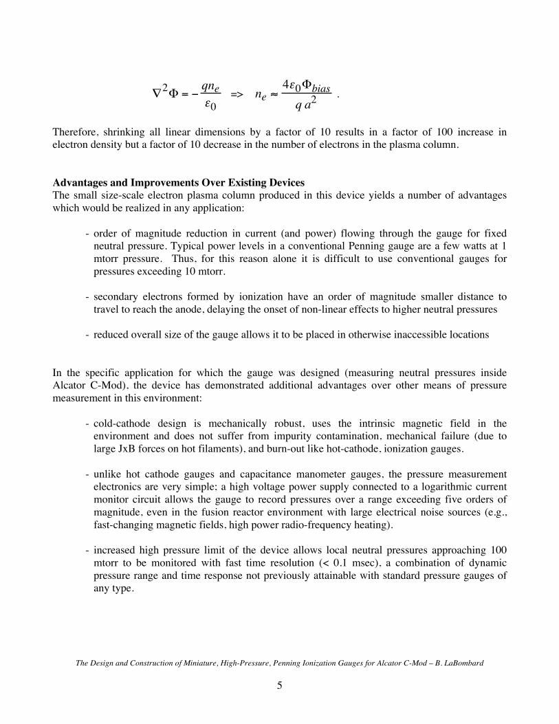
For fixed electrode bias (!bias), the electron density in the plasma column (ne ) increases like one over the square of the column radius (a ). This is because the electron density in this quasi-2D plasma is governed by Poisson's equation with boundary conditions set by the electrode bias,
The Design and Construction of Miniature, High-Pressure, Penning Ionization Gauges for Alcator C-Mod – B. LaBombard 5
!2" = #qne$0
=> ne !4"0#biasq a2
.
Therefore, shrinking all linear dimensions by a factor of 10 results in a factor of 100 increase in electron density but a factor of 10 decrease in the number of electrons in the plasma column. Advantages and Improvements Over Existing Devices The small size-scale electron plasma column produced in this device yields a number of advantages which would be realized in any application:
- order of magnitude reduction in current (and power) flowing through the gauge for fixed
neutral pressure. Typical power levels in a conventional Penning gauge are a few watts at 1 mtorr pressure. Thus, for this reason alone it is difficult to use conventional gauges for pressures exceeding 10 mtorr.
- secondary electrons formed by ionization have an order of magnitude smaller distance to
travel to reach the anode, delaying the onset of non-linear effects to higher neutral pressures - reduced overall size of the gauge allows it to be placed in otherwise inaccessible locations
In the specific application for which the gauge was designed (measuring neutral pressures inside Alcator C-Mod), the device has demonstrated additional advantages over other means of pressure measurement in this environment:
- cold-cathode design is mechanically robust, uses the intrinsic magnetic field in the environment and does not suffer from impurity contamination, mechanical failure (due to large JxB forces on hot filaments), and burn-out like hot-cathode, ionization gauges.
- unlike hot cathode gauges and capacitance manometer gauges, the pressure measurement
electronics are very simple; a high voltage power supply connected to a logarithmic current monitor circuit allows the gauge to record pressures over a range exceeding five orders of magnitude, even in the fusion reactor environment with large electrical noise sources (e.g., fast-changing magnetic fields, high power radio-frequency heating).
- increased high pressure limit of the device allows local neutral pressures approaching 100
mtorr to be monitored with fast time resolution (< 0.1 msec), a combination of dynamic pressure range and time response not previously attainable with standard pressure gauges of any type.

The Design and Construction of Miniature, High-Pressure, Penning Ionization Gauges for Alcator C-Mod – B. LaBombard 6
Fig. 3 - Time traces taken during a plasma pulse in the Alcator C-Mod plasma fusion reactor: (a) pressure
reading from miniature high-pressure Penning gauge, (b) pressure reading from a standard capacitance manometer (connected via piping to a slightly different location), (c) magnetic field strength in center of vacuum chamber, (d) plasma current in magnetically confined fusion plasma.
The top panel in figure 1 shows molecular deuterium gas pressure as a function of time measured by a prototype miniature high-pressure Penning gauge. This gauge was situated in the divertor region of the Alcator C-Mod plasma fusion research reactor. Pressures up to 60 mtorr are measured by the gauge in this case. This is about an order of magnitude above the operating range for standard Penning gauges. A capacitance manometer with piping connected to another region of the divertor (~50 msec response time) shows a similar overall time history. After the plasma current drops to zero (see last panel), pressures in the vacuum chamber equilibrate and both gauges read the same pressures. Although the magnetic field strength changes by a factor of ~2 during the period of time after 1.5 seconds, no discernable influence of this variation is seen on the miniature high-pressure Penning gauge pressure reading. Applications The miniature high-pressure Penning gauge was conceived and developed to help solve the problem of measuring, in-situ, neutral pressures with fast time response in a high performance experimental plasma fusion experiment. Other fusion research facilities may also find this device useful. A broader application may include general vacuum pressure measurement in systems that operate over the range
Minature High Pressure Penning Gauge (mtorr)
Capacitance Manometer (mtorr)
Magnetic Field Strength (tesla)
-1 0 1 2
Plasma Current (MA)
0
20
40
60
0
20
40
60
0
2
4
6
00.20.40.60.8
Time (seconds)
(a)
(b)
(c)
(d)

The Design and Construction of Miniature, High-Pressure, Penning Ionization Gauges for Alcator C-Mod – B. LaBombard 7
of pressures, 10-6 to 0.1 torr, a regime where one normally must employ different types of gauges (e.g., hot-filament ionization gauge, thermocouple gauge, capacitance manometer) to dynamically cover the same range. The robust cold-cathode design and its inherently simple instrumentation could offer further advantages where high reliability in harsh vacuum environments and low component cost is desired. Practical Considerations One must keep in mind that unlike hot-cathode gauges, Penning gauges exhibit the following unique behaviors:
- Penning gauges ‘turn on’ only under conditions when the magnetic field is present and electron emission from the cold cathode (field emission and/or photoelectric induced) is sufficient to initiate the trapped electron population. In Alcator C-Mod, all miniature Penning gauges reliably ‘turn on’ at initiation (breakdown) of the tokamak plasma discharge. It should be noted the gauges do not necessarily turn on when magnetic field and gas is present but a tokamak discharge has not been initiated.
- Penning gauges are known to exhibit a ‘mode jumping’ behavior in which the electron density in
the gauge can change abruptly. The miniature Penning gauges appear to exhibit this behavior. Apparently, the confinement of the electrons in the Penning trap depends on different rotational modes in the cavity. Thus the calibration of the gauge (i.e., neutral density versus collected current) can jump unexpectedly. For this reason Alcator C-Mod does not rely on the miniature Penning gauges for absolute neutral density measurements. Instead, the Penning gauge signals are cross-calibrated against baratron (or hot cathode ionization) gauges during a time in the tokamak plasma pulse when both gauges should measure the same neutral density. Thus the Penning gauges are used to extend baratron gauge measurements to faster time response and to spatial regions of the device not accessible to a baratron gauge. In principle, it may be possible to use two or more Penning gauges at the same location as ‘coincident detectors’ – to detect and correct for cases in which one or more gauges experience a ‘mode jump’ event.
Detailed Design Information Appendices A and B provide more details on the mechanical design and an electrical circuit diagram. Pictures of miniature high-pressure Penning ionization gauges installed in Alcator C-Mod are included in Appendix C. Measurements of a modulation in divertor neutral gas density in response to a divertor bypass ‘flapper’ system [Pitcher, C.S., LaBombard, B., Danforth, R., Pina, W., Silveira, M., and Parkin, B., "Divertor bypass in the Alcator C-Mod tokamak," Rev. Sci. Instrum. 72 (2001) 103] is shown in the last figure of Appendix C. Acknowledgement This research was supported by U.S. Department of Energy Coop. Agreement DE-FC02-99ER54512.

The Design and Construction of Miniature, High-Pressure, Penning Ionization Gauges for Alcator C-Mod – B. LaBombard 8
Appendix A - Mechanical Drawings

The Design and Construction of Miniature, High-Pressure, Penning Ionization Gauges for Alcator C-Mod – B. LaBombard 9

The Design and Construction of Miniature, High-Pressure, Penning Ionization Gauges for Alcator C-Mod – B. LaBombard
10

The Design and Construction of Miniature, High-Pressure, Penning Ionization Gauges for Alcator C-Mod – B. LaBombard
11

The Design and Construction of Miniature, High-Pressure, Penning Ionization Gauges for Alcator C-Mod – B. LaBombard
12

The Design and Construction of Miniature, High-Pressure, Penning Ionization Gauges for Alcator C-Mod – B. LaBombard
13

The Design and Construction of Miniature, High-Pressure, Penning Ionization Gauges for Alcator C-Mod – B. LaBombard
14

The Design and Construction of Miniature, High-Pressure, Penning Ionization Gauges for Alcator C-Mod – B. LaBombard
15
Appendix B – Circuit Diagram
+1
5V
-15
V
10 k
0.1u
f
2 vo
lts p
er d
ecad
e:Vo
ut =
-2x(
5+Lo
g10(
Isig
))
Isig
(A)
Vou
t (V)
5E-3
-5.4
01E
-3 -4
1E-5
01E
-7 4
1E-9
8
0-3k
VHi
gh v
olta
gepo
wer
sup
ply
110V
AC
SHV
- to
Penn
ing
Gau
geCa
thod
e+
-SH
V sh
ield
conn
ecte
dto
shi
eld
box
Shie
ld b
ox is
isol
ated
from
Rac
k Sh
elf
Penn
ing
Gau
ge B
ias
and
Log
Ampl
ier
Circ
uit
B.
La
Bo
mb
ard
Re
vis
ed
9/1
3/2
00
5
Te
l.:(
61
7)
25
3-7
26
4 F
ax:
(61
7)
25
3-0
62
7
M.I.
T. P
lasm
a Fu
sion
Cen
ter
175
Alba
ny S
t.Ca
mbr
idge
, MA
0213
9
+/- 1
5VDC
pow
er s
uppl
y
1.5K
E51A
volta
gesu
ppre
ssor
(50V
bre
akdo
wn)
Shie
ld B
ox is
ISO
LATE
D fro
m R
ack
Shel
f
Case
of H
igh
Volta
ge P
ower
Sup
ply
is IS
OLA
TED
with
resp
ect t
o sh
ield
box
Shie
ld o
f MV
conn
ecto
r (an
dca
se o
f H.V
. pow
er s
uppl
y) is
(+) c
onne
ctio
n
Cent
er p
inof
MV
conn
ecto
ris
(-)
conn
ectio
n
Isig
Mou
nt c
ase
of H
.V. s
uppl
yto
shi
eld
box
with
insu
latin
gha
rdw
are
Pin
7
Pin
3
Pin
6
To 1
10V
pow
er s
witc
h an
d po
wer
ligh
t,m
ount
ed o
n fro
nt p
anel
of R
ack
Shel
f
twis
ted
pair
twis
ted
pair
twis
ted
pair
Pin
8
FP
23
0-5
0
1&
3
2&
4
6&
7
8 5
Line
Neut
ral
220V
AC11
0VA
C11
0VA
C
I2
Vre
f-G
ND
Vre
f
7
LOG
112
- +
- +- +
1
14
13
10
Vre
f8
11
9
6 V-
V+
I1V
log
ou
t5
Vcm
GN
D
43
Vo
3
+IN
3-I
N3
7
0.1
uf
+15V
-15
V
4
62 3
OP
A6
27
AU
8
4.0
2k
1%
1k 1%
4.7
uf
+
0.1
uf
1,5
NC
4.7
uf
+
-15
V
+15V
0.1
uf
0.1
uf
1n
f
24
9k
1%
A1
A2
A3
Q1
Q2
=2
.5V
=0
.5V
/de
ca
de
Vo
ut
-2
V/d
eca
de
4 n
f
BNC
shie
ldco
nnec
ted
to s
hiel
dbo
x
Vout
mA
Mon
itor
kV M
onito
r
Isol
ated
BNC
Isol
ated
BNC
Trip
Isol
ated
BNC
(2) 1
N414
8

The Design and Construction of Miniature, High-Pressure, Penning Ionization Gauges for Alcator C-Mod – B. LaBombard
16
Appendix C – Miniature High-Pressure Penning Gauges Installed in Alcator C-Mod

The Design and Construction of Miniature, High-Pressure, Penning Ionization Gauges for Alcator C-Mod – B. LaBombard
17

The Design and Construction of Miniature, High-Pressure, Penning Ionization Gauges for Alcator C-Mod – B. LaBombard
18

The Design and Construction of Miniature, High-Pressure, Penning Ionization Gauges for Alcator C-Mod – B. LaBombard
19

The Design and Construction of Miniature, High-Pressure, Penning Ionization Gauges for Alcator C-Mod – B. LaBombard
20

The Design and Construction of Miniature, High-Pressure, Penning Ionization Gauges for Alcator C-Mod – B. LaBombard
21
Two miniature Penning ionization gauges were installed to sample gas pressures in the C-Mod upper divertor cryopump chamber. (This picture was taken prior to cryopump installation.) An additional gauge was installed to sample gas pressures outside the cryopump chamber.

The Design and Construction of Miniature, High-Pressure, Penning Ionization Gauges for Alcator C-Mod – B. LaBombard
22

The Design and Construction of Miniature, High-Pressure, Penning Ionization Gauges for Alcator C-Mod – B. LaBombard
23
A miniature Penning ionization gauge was installed under and outer divertor module that contained a divertor bypass ‘flapper’ unit [Pitcher, C.S., LaBombard, B., Danforth, R., Pina, W., Silveira, M., and Parkin, B., "Divertor bypass in the Alcator C-Mod tokamak," Rev. Sci. Instrum. 72 (2001) 103]. The next figure shows a modulation in gas pressure measured by this gauge in response to the flapper valve being opened and closed.

The Design and Construction of Miniature, High-Pressure, Penning Ionization Gauges for Alcator C-Mod – B. LaBombard
24
-2
0
20
40
mto
rr Capacitance
Manometer
0.0
0.4
0.8
10 20
m -2
Line-Integral Density
0.0
0.4
0.8
MA
Plasma Current
0 2
4 6
tesl
a
Toroidal Field
0 20
40 60
mto
rr Mini-Penning
Gauge 2 0
amps
Divertor Flap Current
0.0 0.5 1.0 1.5 2.0 seconds
Results from Miniature Penning Gauge in Alcator C-Mod
B. LaBombard 1/28/03
Traces from a typical discharge are shown. A capacitance manometer records the pressure at the end of a vertical port tube, connected to under a divertor module. A "Miniature Penning Gauge" is located right under a divertor flap in an adjacent divertor module. Mini-Penning Gauge: -> uses ambient magnetic field for operation -> miniature, cold cathode design -> records fast pressure decrease at flap opening -> upper pressure limit is ~10x normal Penning gauge