The definition of a geophysically meaningful International Terrestrial Reference System Problems and...
29
The definition of a geophysically meaningful International Terrestrial Reference System Problems and prospects Athanasios Dermanis Department of Geodesy and Surveying Aristotle University of Thessaloniki X Y Z EGU General Assembly 2006 April 2-7, Vienna
-
Upload
turner-holness -
Category
Documents
-
view
215 -
download
0
Transcript of The definition of a geophysically meaningful International Terrestrial Reference System Problems and...
The definition of a geophysically meaningful International Terrestrial Reference System
Problems and prospects
The definition of a geophysically meaningful International Terrestrial Reference System
Problems and prospects
Athanasios Dermanis
Department of Geodesy and SurveyingAristotle University of Thessaloniki X
Y
Z
EGU General Assembly 2006April 2-7, Vienna
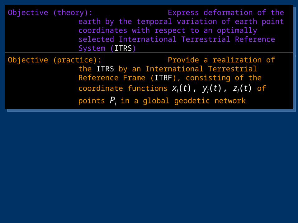
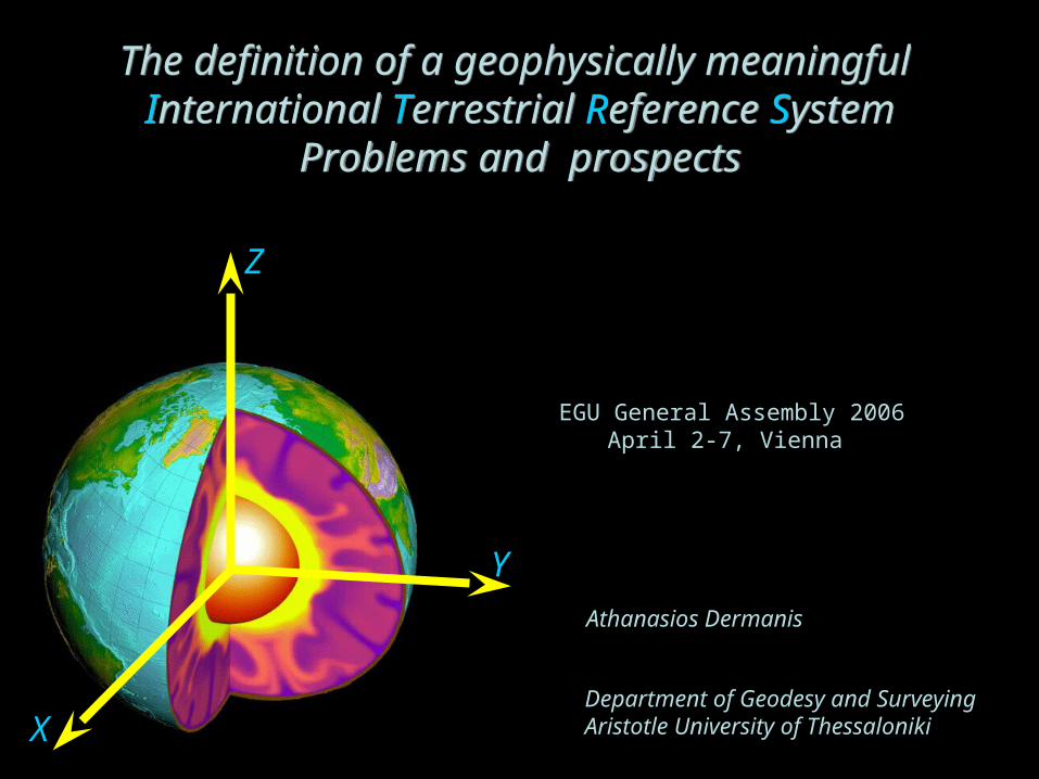
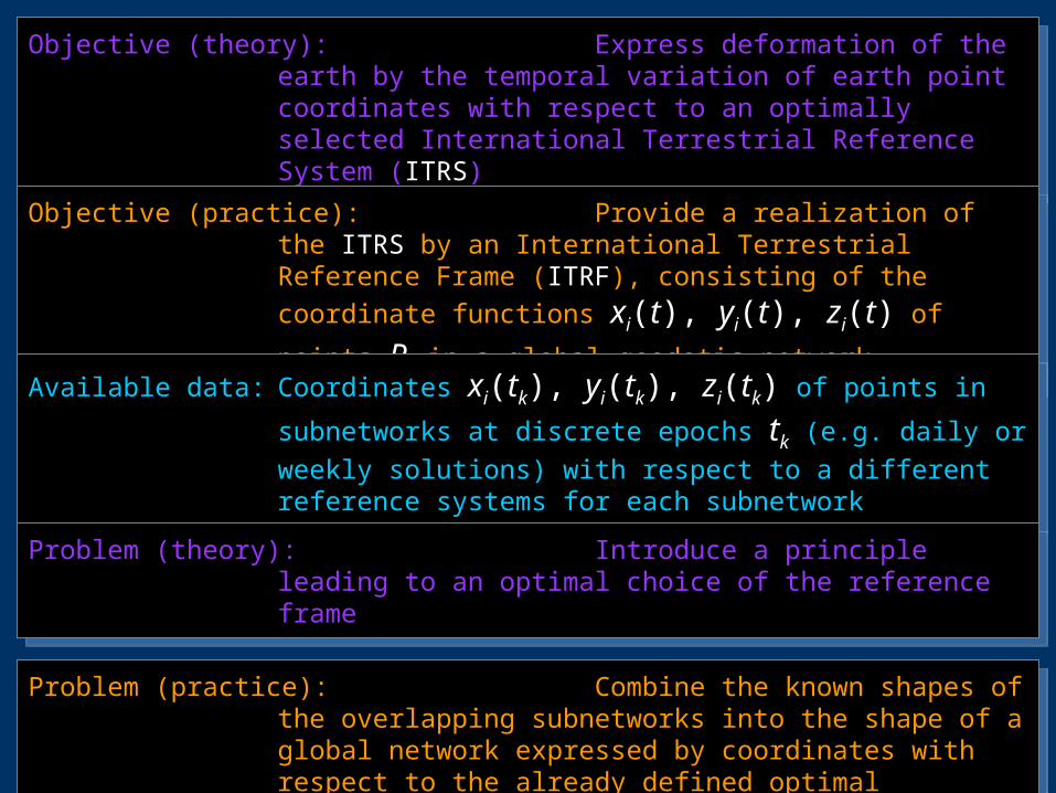
Objective (theory): Express deformation of the earth by the temporal variation of earth point coordinates with respect to an optimally selected International Terrestrial Reference System (ITRS)
Objective (theory): Express deformation of the earth by the temporal variation of earth point coordinates with respect to an optimally selected International Terrestrial Reference System (ITRS)
Objective (practice): Provide a realization of the ITRS by an International Terrestrial Reference Frame (ITRF), consisting of the coordinate functions xi(t), yi(t), zi(t) of
points Pi in a global geodetic network
Objective (practice): Provide a realization of the ITRS by an International Terrestrial Reference Frame (ITRF), consisting of the coordinate functions xi(t), yi(t), zi(t) of
points Pi in a global geodetic network
Objective (theory): Express deformation of the earth by the temporal variation of earth point coordinates with respect to an optimally selected International Terrestrial Reference System (ITRS)
Objective (theory): Express deformation of the earth by the temporal variation of earth point coordinates with respect to an optimally selected International Terrestrial Reference System (ITRS)
Objective (practice): Provide a realization of the ITRS by an International Terrestrial Reference Frame (ITRF), consisting of the coordinate functions xi(t), yi(t), zi(t) of
points Pi in a global geodetic network
Objective (practice): Provide a realization of the ITRS by an International Terrestrial Reference Frame (ITRF), consisting of the coordinate functions xi(t), yi(t), zi(t) of
points Pi in a global geodetic network
Available data: Coordinates xi(tk), yi(tk), zi(tk) of points in subnetworks at
discrete epochs tk (e.g. daily or weekly solutions) with respect to a different reference systems for each subnetwork
Available data: Coordinates xi(tk), yi(tk), zi(tk) of points in subnetworks at
discrete epochs tk (e.g. daily or weekly solutions) with respect to a different reference systems for each subnetwork
Objective (theory): Express deformation of the earth by the temporal variation of earth point coordinates with respect to an optimally selected International Terrestrial Reference System (ITRS)
Objective (theory): Express deformation of the earth by the temporal variation of earth point coordinates with respect to an optimally selected International Terrestrial Reference System (ITRS)
Objective (practice): Provide a realization of the ITRS by an International Terrestrial Reference Frame (ITRF), consisting of the coordinate functions xi(t), yi(t), zi(t) of
points Pi in a global geodetic network
Objective (practice): Provide a realization of the ITRS by an International Terrestrial Reference Frame (ITRF), consisting of the coordinate functions xi(t), yi(t), zi(t) of
points Pi in a global geodetic network
Available data: Coordinates xi(tk), yi(tk), zi(tk) of points in subnetworks at
discrete epochs tk (e.g. daily or weekly solutions) with respect to a different reference systems for each subnetwork
Available data: Coordinates xi(tk), yi(tk), zi(tk) of points in subnetworks at
discrete epochs tk (e.g. daily or weekly solutions) with respect to a different reference systems for each subnetwork
Problem (theory): Introduce a principle leading to an optimal choice of the reference frame
Problem (theory): Introduce a principle leading to an optimal choice of the reference frame
Problem (practice): Combine the known shapes of the overlapping subnetworks into the shape of a global network expressed by coordinates with respect to the already defined optimal reference system
Problem (practice): Combine the known shapes of the overlapping subnetworks into the shape of a global network expressed by coordinates with respect to the already defined optimal reference system
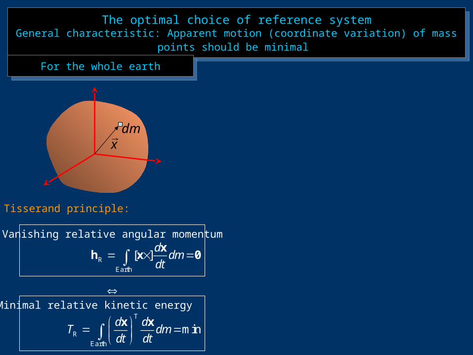
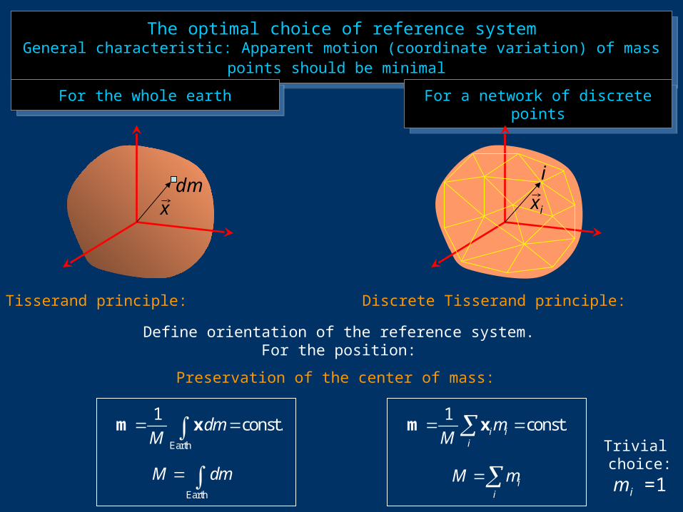
The optimal choice of reference systemGeneral characteristic: Apparent motion (coordinate variation) of mass points should
be minimal
The optimal choice of reference systemGeneral characteristic: Apparent motion (coordinate variation) of mass points should
be minimal
For the whole earthFor the whole earth
dmx
R [ ]d
dmdt
x
h x 0Earth
T
R mind d
T dmdt dt
x x
Earth
Tisserand principle:
Vanishing relative angular momentum
Minimal relative kinetic energy

The optimal choice of reference systemGeneral characteristic: Apparent motion (coordinate variation) of mass points should
be minimal
The optimal choice of reference systemGeneral characteristic: Apparent motion (coordinate variation) of mass points should
be minimal
For the whole earthFor the whole earth For a network of discrete pointsFor a network of discrete points
dmx
R [ ]d
dmdt
x
h x 0Earth
T
R mind d
T dmdt dt
x x
Earth
Tisserand principle:
Vanishing relative angular momentum
Minimal relative kinetic energy
R [ ] ii i
i
dm
dt x
h x 0
T
R mini ii
i
d dT m
dt dt
x x
Discrete Tisserand principle:
Vanishing relative angular momentum
Minimal relative kinetic energy
xi
i
The optimal choice of reference systemGeneral characteristic: Apparent motion (coordinate variation) of mass points should
be minimal
The optimal choice of reference systemGeneral characteristic: Apparent motion (coordinate variation) of mass points should
be minimal
For the whole earthFor the whole earth For a network of discrete pointsFor a network of discrete points
dmx
Earth
M dm
Tisserand principle:
1const.i i
i
mM
m x
Discrete Tisserand principle:
Define orientation of the reference system.For the position:
xi
i
Earth
1const.dm
M m x
ii
M m
Preservation of the center of mass:
Trivial choice:mi =1
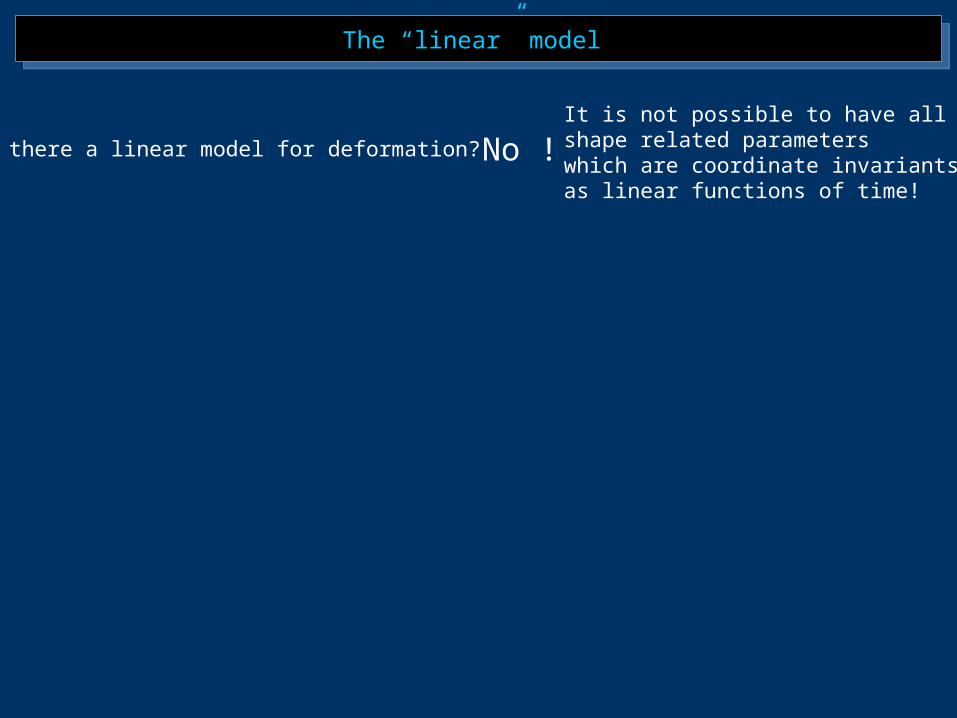
The “linear” model The “linear” model
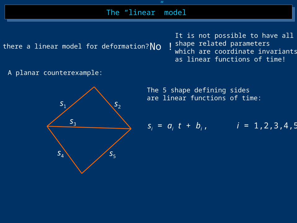
Is there a linear model for deformation? No !It is not possible to have all shape related parameterswhich are coordinate invariantsas linear functions of time!
The “linear” model The “linear” model
Is there a linear model for deformation? No !
A planar counterexample:
s1 s2
s4 s5
s3 si = ai t + bi , i = 1,2,3,4,5
The 5 shape defining sides are linear functions of time:
It is not possible to have all shape related parameterswhich are coordinate invariantsas linear functions of time!
The “linear” model The “linear” model
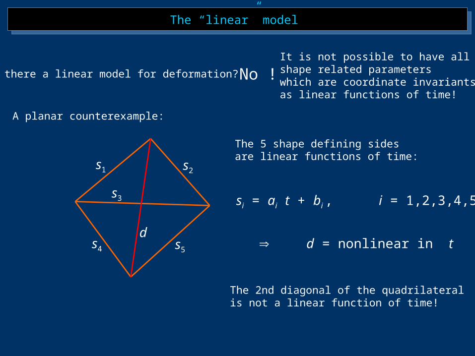
Is there a linear model for deformation? No !
A planar counterexample:
s1 s2
s4 s5
s3
d
si = ai t + bi , i = 1,2,3,4,5
d = nonlinear in t
The 5 shape defining sides are linear functions of time:
The 2nd diagonal of the quadrilateral is not a linear function of time!
It is not possible to have all shape related parameterswhich are coordinate invariantsas linear functions of time!
The “linear” model The “linear” model
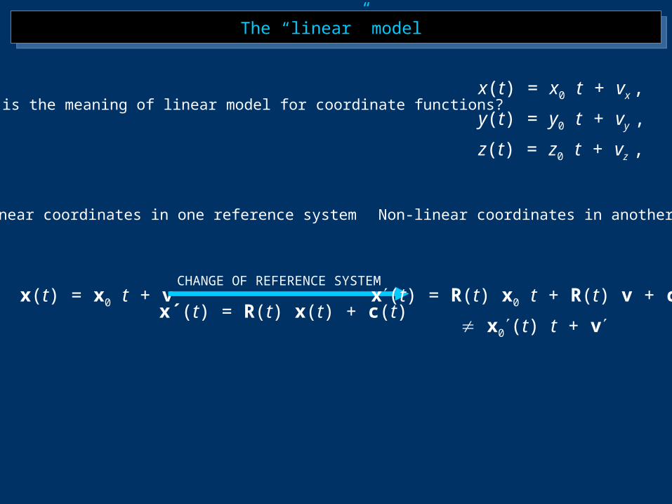
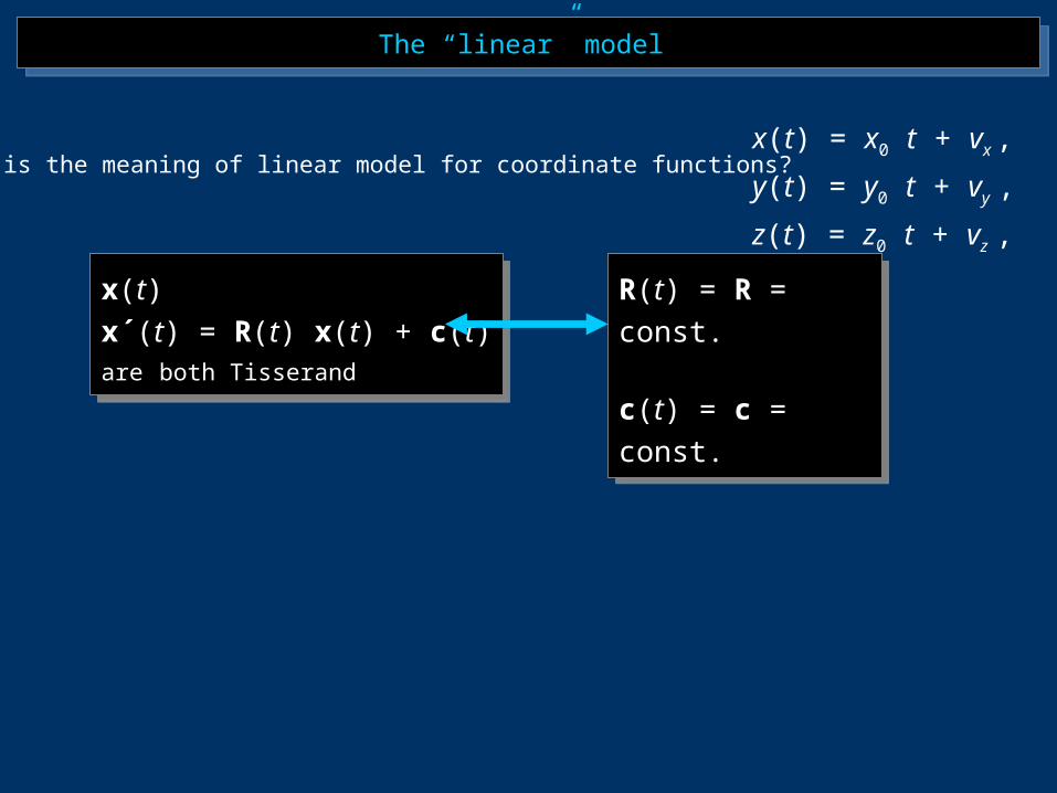
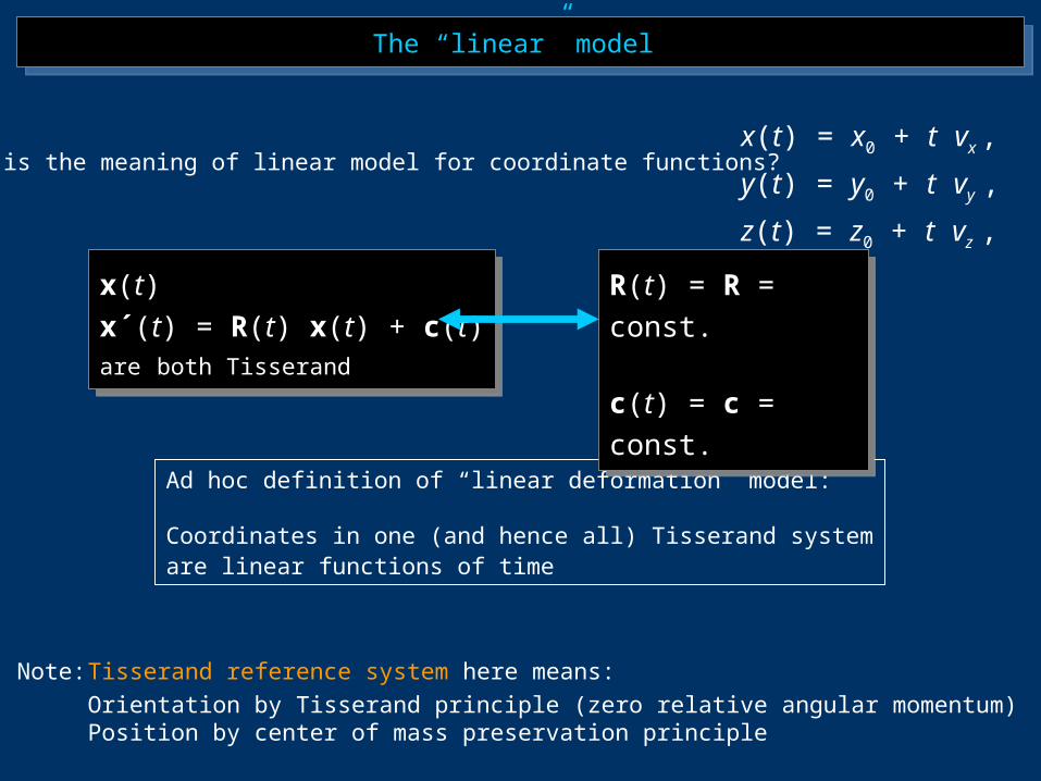
What is the meaning of linear model for coordinate functions?
Linear coordinates in one reference system
x(t) = x0 t + vx ,
y(t) = y0 t + vy ,
z(t) = z0 t + vz ,
x(t) = x0 t + v x(t) = R(t) x0 t + R(t) v + c(t)
x0(t) t + vx´(t) = R(t) x(t) + c(t)
Non-linear coordinates in another
CHANGE OF REFERENCE SYSTEM
The “linear” model The “linear” model
x(t)
x´(t) = R(t) x(t) + c(t)are both Tisserand
x(t)
x´(t) = R(t) x(t) + c(t)are both Tisserand
R(t) = R = const.
c(t) = c = const.
R(t) = R = const.
c(t) = c = const.
What is the meaning of linear model for coordinate functions? x(t) = x0 t + vx ,
y(t) = y0 t + vy ,
z(t) = z0 t + vz ,
The “linear” model The “linear” model
Ad hoc definition of “linear deformation” model:
Coordinates in one (and hence all) Tisserand systemare linear functions of time
x(t)
x´(t) = R(t) x(t) + c(t)are both Tisserand
x(t)
x´(t) = R(t) x(t) + c(t)are both Tisserand
Note: Tisserand reference system here means:Orientation by Tisserand principle (zero relative angular momentum)Position by center of mass preservation principle
R(t) = R = const.
c(t) = c = const.
R(t) = R = const.
c(t) = c = const.
What is the meaning of linear model for coordinate functions? x(t) = x0 + t vx ,
y(t) = y0 + t vy ,
z(t) = z0 + t vz ,
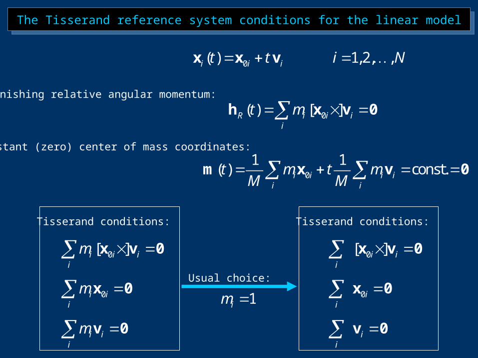
The Tisserand reference system conditions for the linear modelThe Tisserand reference system conditions for the linear model
0( )i i it t x x v 1,2, ,i N
0( ) [ ]R i i ii
t m h x v 0
0
1 1( ) const.i i i i
i i
t m t mM M
m x v 0
Vanishing relative angular momentum:
Constant (zero) center of mass coordinates:
Tisserand conditions:
0[ ]i i ii
m x v 0
0i ii
m x 0
i ii
m v 0
Usual choice:
1im
Tisserand conditions:
0[ ]i ii
x v 0
0ii
x 0
ii
v 0
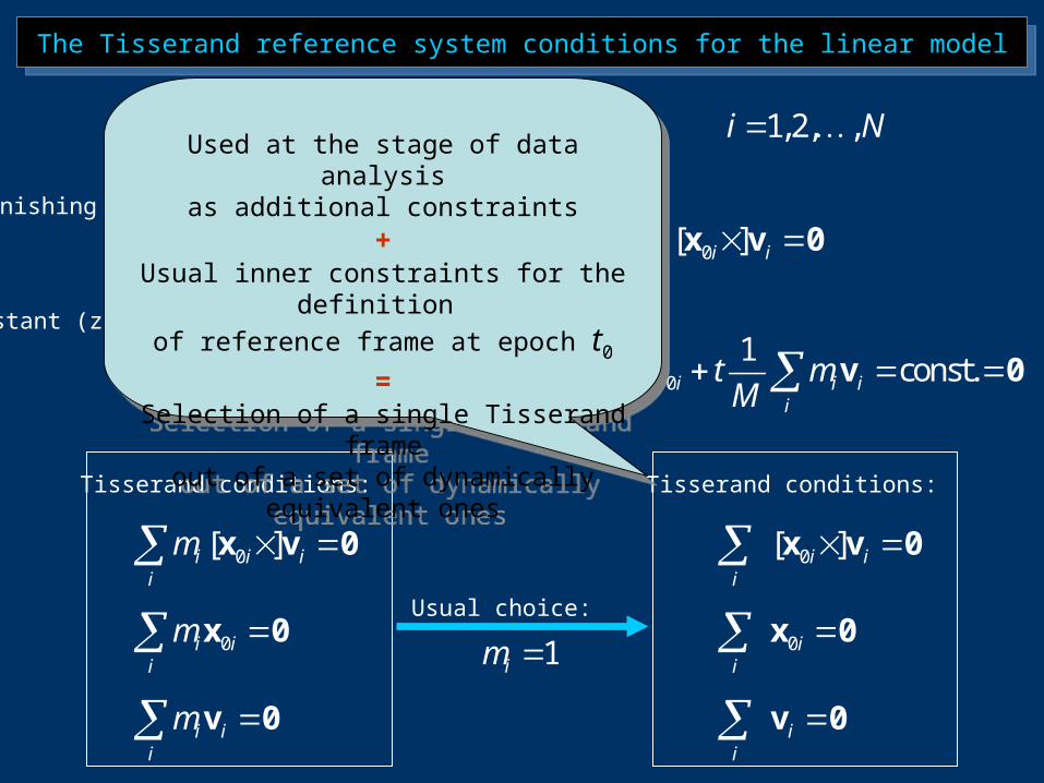
Used at the stage of data analysisas additional constraints
+Usual inner constraints for the
definition of reference frame at epoch t0
=Selection of a single Tisserand frameout of a set of dynamically equivalent
ones
Used at the stage of data analysisas additional constraints
+Usual inner constraints for the
definition of reference frame at epoch t0
=Selection of a single Tisserand frameout of a set of dynamically equivalent
ones
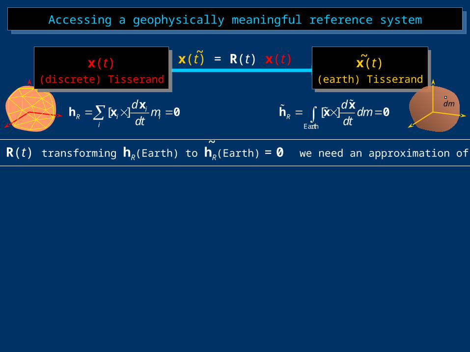
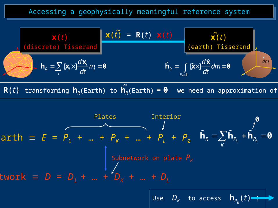
Accessing a geophysically meaningful reference systemAccessing a geophysically meaningful reference system
x(t)(earth) Tisserand
x(t)(earth) Tisserand
Earth
[ ]R
ddm
dt
xh x 0
[ ] iR i i
i
dm
dt x
h x 0
~x(t) = R(t) x(t)~x(t)
(discrete) Tisserand
x(t)(discrete) Tisserand
dm
To access R(t) transforming hR(Earth) to hR(Earth) = 0 we need an approximation of hR(Earth)~
Earth E = P1 + … + PK + … + PL + P0
Network D = D1 + … + DK + … + DL
Plates Interior
Subnetwork on plate PK
To access R(t) transforming hR(Earth) to hR(Earth) = 0 we need an approximation of hR(Earth)
0KR P PK
h h h 0
0
Use DK to access hPK(t) !
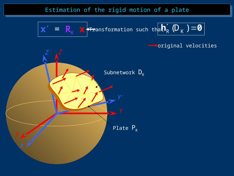
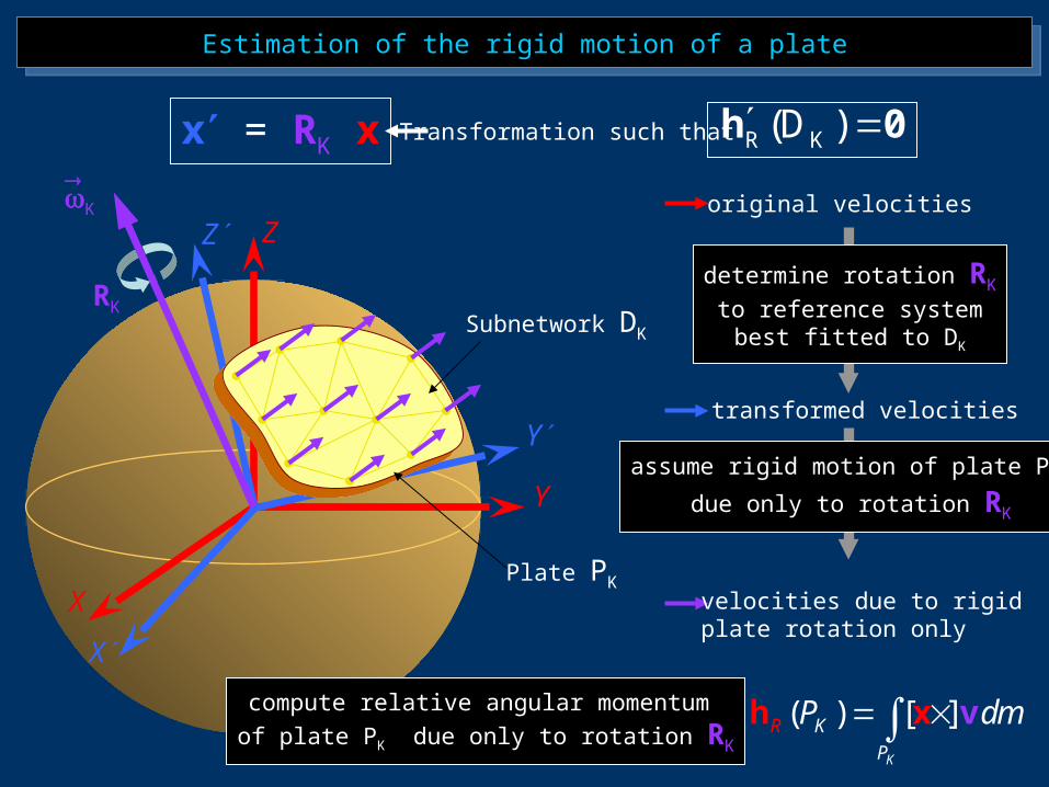
Estimation of the rigid motion of a plateEstimation of the rigid motion of a plate
Plate PK
Subnetwork DK
x = RK x Transformation such that R K(D ) h 0
original velocities
X
Y
Z
X
Y
Z
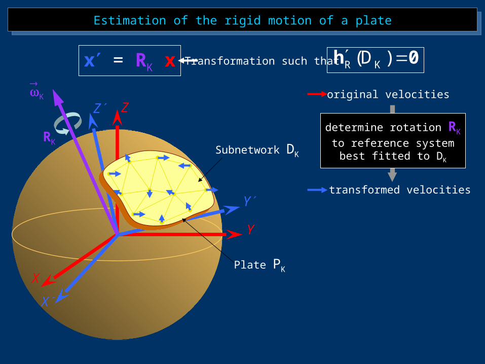
Estimation of the rigid motion of a plateEstimation of the rigid motion of a plate
Plate PK
Subnetwork DK
RK
K
x = RK x Transformation such that R K(D ) h 0
original velocities
transformed velocities
determine rotation RK
to reference systembest fitted to DK
X
Y
Z
X
Y
Z
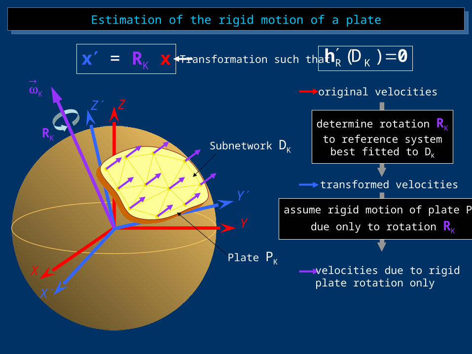
Estimation of the rigid motion of a plateEstimation of the rigid motion of a plate
Plate PK
Subnetwork DK
RK
K
x = RK x Transformation such that R K(D ) h 0
original velocities
transformed velocities
velocities due to rigidplate rotation only
determine rotation RK
to reference systembest fitted to DK
assume rigid motion of plate PK
due only to rotation RK
X
Y
Z
X
Y
Z
Estimation of the rigid motion of a plateEstimation of the rigid motion of a plate
Plate PK
Subnetwork DK
RK
K
x = RK x Transformation such that R K(D ) h 0
original velocities
transformed velocities
velocities due to rigidplate rotation only
determine rotation RK
to reference systembest fitted to DK
assume rigid motion of plate PK
due only to rotation RK
compute relative angular momentum of plate PK due only to rotation RK
( ) [ ]K
KR
P
P dm h x v
X
Y
Z
X
Y
Z
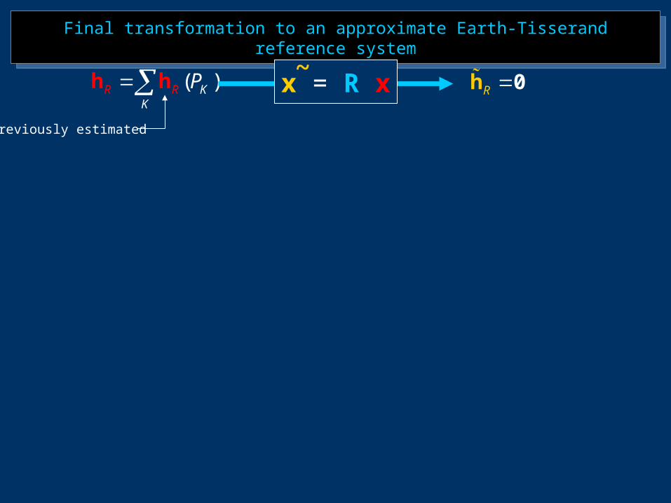
Final transformation to an approximate Earth-Tisserand reference systemFinal transformation to an approximate Earth-Tisserand reference system
( )RK
R KPh h R 0hx = R x~
Previously estimated
Final transformation to an approximate Earth-Tisserand reference systemFinal transformation to an approximate Earth-Tisserand reference system
( )RK
R KPh h R 0hx = R x~
Previously estimated
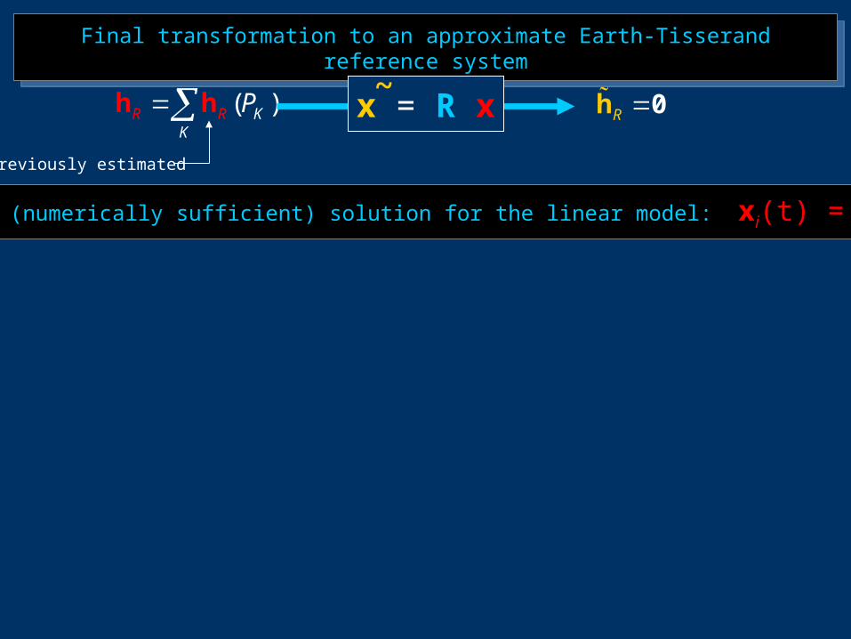
Approximate (numerically sufficient) solution for the linear model: xi(t) = x0i + t vi
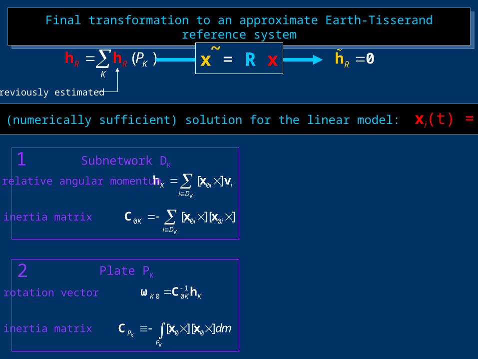
Final transformation to an approximate Earth-Tisserand reference systemFinal transformation to an approximate Earth-Tisserand reference system
( )RK
R KPh h R 0hx = R x~
Previously estimated
Approximate (numerically sufficient) solution for the linear model: xi(t) = x0i + t vi
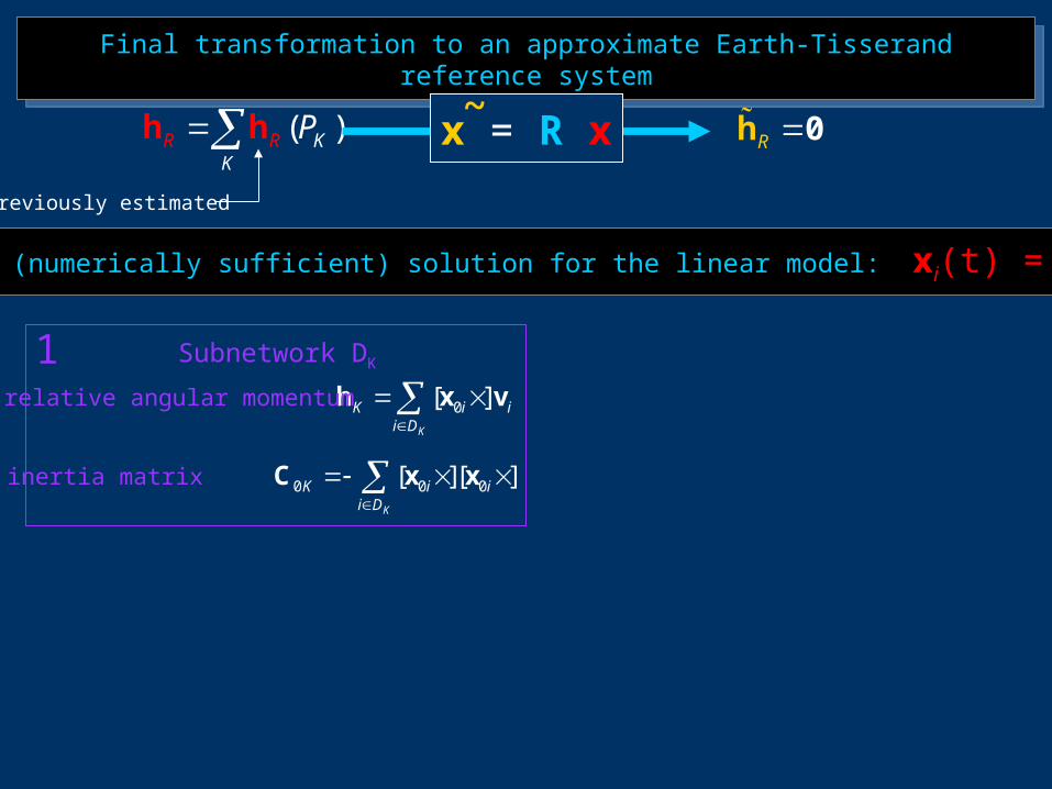
0[ ]K
K i ii D
h x v
0 0 0[ ][ ]K
K i ii D
C x x
relative angular momentum
inertia matrix
Subnetwork DK1
Final transformation to an approximate Earth-Tisserand reference systemFinal transformation to an approximate Earth-Tisserand reference system
( )RK
R KPh h R 0hx = R x~
Previously estimated
Approximate (numerically sufficient) solution for the linear model: xi(t) = x0i + t vi
0[ ]K
K i ii D
h x v
0 0 0[ ][ ]K
K i ii D
C x x
10 0K K K
ω C h
0 0[ ][ ]K
K
P
P
dm C x x
relative angular momentum
inertia matrix
rotation vector
inertia matrix
Subnetwork DK
Plate PK
1
2
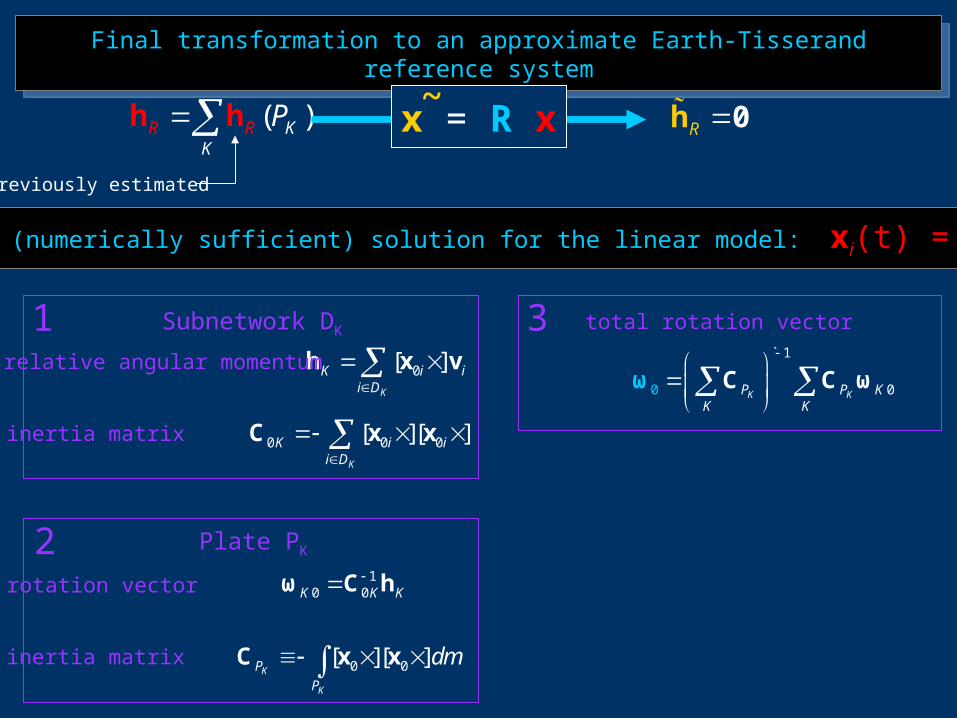
Final transformation to an approximate Earth-Tisserand reference systemFinal transformation to an approximate Earth-Tisserand reference system
( )RK
R KPh h R 0hx = R x~
Previously estimated
Approximate (numerically sufficient) solution for the linear model: xi(t) = x0i + t vi
0[ ]K
K i ii D
h x v
0 0 0[ ][ ]K
K i ii D
C x x
10 0K K K
ω C h
0 0[ ][ ]K
K
P
P
dm C x x
00
` 1
K KP P KK K
C ωω C
relative angular momentum
inertia matrix
rotation vector
inertia matrix
Subnetwork DK
Plate PK
total rotation vector1
2
3
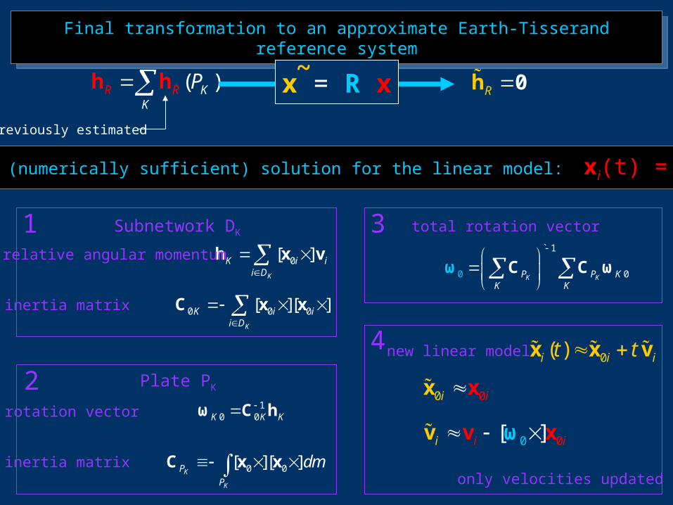
Final transformation to an approximate Earth-Tisserand reference systemFinal transformation to an approximate Earth-Tisserand reference system
( )RK
R KPh h R 0hx = R x~
Previously estimated
Approximate (numerically sufficient) solution for the linear model: xi(t) = x0i + t vi
0[ ]K
K i ii D
h x v
0 0 0[ ][ ]K
K i ii D
C x x
10 0K K K
ω C h
0 0[ ][ ]K
K
P
P
dm C x x
00
` 1
K KP P KK K
C ωω C
0( )i i it t x x v
0 0ii x x
0 0[ ]i i i ωv xv
relative angular momentum
inertia matrix
rotation vector
inertia matrix
Subnetwork DK
Plate PK
total rotation vector1
2
3
4 new linear model
only velocities updated !

A copy of this presentation can be downloaded from:
http://der.topo.auth.gr
A copy of this presentation can be downloaded from:
http://der.topo.auth.gr
Thanks for your attention !
VI Hotine-Marussi Symposium of Theoretical and Computational Geodesy:
Challenge and Role of Modern GeodesyMay 29 - June 2, 2006, Wuhan, China
VI Hotine-Marussi Symposium of Theoretical and Computational Geodesy:
Challenge and Role of Modern GeodesyMay 29 - June 2, 2006, Wuhan, China
the Intercommission Committee on Theory (ICCT) of the International Association of Geodesy (IAG)