The Cornell Caltech Atacama Telescope: progress and plans 2010 ...
12
The Cornell Caltech Atacama Telescope: Progress and Plans 2010 T. Sebring et al. for the CCAT Collaboration Center for Radiophysics and Space Research, Cornell University, Ithaca NY 14853 Copyright 2010 Society of Photo-Optical Instrumentation Engineers. This paper was published in Ground-based and Airborne Telescopes III, Proc. SPIE 7733, 77331X, and is made available as an electronic reprint with permission of SPIE. One print or electronic copy may be made for personal use only. Systematic or multiple reproduction, distribution to multiple locations via electronic or other means, duplication of any material in this paper for a fee or for commercial purposes, or modification of the content of the paper are prohibited.
Transcript of The Cornell Caltech Atacama Telescope: progress and plans 2010 ...

The Cornell Caltech Atacama Telescope: Progress and Plans 2010
T. Sebring et al. for the CCAT Collaboration
Center for Radiophysics and Space Research, Cornell University, Ithaca NY 14853
Copyright 2010 Society of Photo-Optical Instrumentation Engineers.
This paper was published in Ground-based and Airborne Telescopes III, Proc. SPIE 7733, 77331X, and is made available as an electronic reprint with permission of SPIE. One print or electronic copy may be made for personal use only. Systematic or multiple reproduction, distribution to multiple locations via electronic or other means, duplication of any material in this paper for a fee or for commercial purposes, or modification of the content of the paper are prohibited.
The Cornell Caltech Atacama Telescope: Progress and Plans 2010
T. Sebring et al , for the CCAT Collaboration
Center for Radiophysics and Space Research, Cornell University, Ithaca, NY 14853;
Acknowledgements: This paper draws on the work of many people at the various CCAT partner institutions and contractors. Their efforts are deeply appreciated.
ABSTRACT
The CCAT Project is an effort to construct a 25 meter aperture telescope above 5600 meters altitude operating down to wavelengths as short as 200 µm. CCAT has developed some new and innovative approaches to telescope and optics design, added new partners to the project, and has plans for substantially increased activities over the next two years. Begun by Cornell University and the California Institute of Technology, CCAT currently has six national and university partners. Funding has been increased and significant technical activities are underway to investigate the key enabling technologies. Areas of development include telescope optical design, mount design, application of CFRP materials to the telescope, sensing and control of primary mirror segments, and control system architecture. Schedules and budgets for the Project have been updated and an overall approach leading to first light in 2016-2017 has been developed. CCAT promises to have a significant scientific impact on submillimeter astronomy and the prospects for success has never looked better. Keywords: Atacama, submillimeter, telescope.
1. INTRODUCTION CCAT will be a 25 meter submillimeter wave telescope to be constructed near the summit of Cerro Chajnantor in the CONICYT Science Preserve in the Atacama region. The project has been under development since 2003; founded by Cornell and Caltech. Significant progress on all fronts has been realized over the past two years. The Consortium continues to grow, key personnel have been added, studies have been performed at the partner institutions and industrial concerns, and the organizational and business posture of CCAT continues to improve. CCAT is now poised for a substantial advance toward construction and operation. The information that follows provides an update on the organizational and technical status of CCAT.
2. BACKGROUND Background: Development of CCAT began under an MOU between Cornell and Caltech in February of 2004. Since that time substantial progress has been made in development of designs, studies performed by industry as well as Cornell and Caltech personnel, and in growth of the CCAT partnership. CCAT remains a 25 meter aperture telescope with a shortest planned operating wavelength of 200 µm sited at 5600 m altitude on Cerro Chajnantor in the Atacama CONICYT Science Preserve in Chile. Recently CCAT has adopted a more aggressive 1degree field of view and design studies are taking the telescope toward implementation of a CFRP primary mirror truss. CCAT has improved designs for primary mirror segments which are likely to be made up of fairly large CFRP "rafts" each of which carry multiple front surface "tiles" mounted on manual adjustors. Closed loop active control of segments based on edge sensor measurements is held in reserve while initial operation is intended to be by the use of "look-up" tables to compensate for gravitational and thermal distortions. CCAT has funded several industrial studies and activities are ongoing. In addition to a study addressing primary mirror segment design, CCAT has studied control system options, design of the CFRP truss, composite structures and components, and sensing and control of primary mirror segment positions.
Invited Paper
Ground-based and Airborne Telescopes III, edited by Larry M. Stepp, Roberto Gilmozzi, Helen J. HallProc. of SPIE Vol. 7733, 77331X · © 2010 SPIE · CCC code: 0277-786X/10/$18 · doi: 10.1117/12.857334
Proc. of SPIE Vol. 7733 77331X-1

CCAT was inthe ConsortiuScience and Waterloo.) Icommitment Northwest Rthe two initcollaborationdiscussions wcorporation aperhaps as eaThe project hwithin the ne
4.1. OverviCCAT is engaddress the intruss to replarafts. These design.
4.2. 1 DegreThe initial doutside the eFoV of the tetelescope strufield instrum1st light at thcamera requi
nitially foundeum including Technology FIn February ofto join CCAT
Rhine Westphaltial Canadian n now totalingwith other potas the businessarly as Octoberhopes to spendext three years.
ew of design cgaged in studiencrease of the t
ace the steel denew ideas will
ee FOV designesign for CCAlevation bearinelescope is limucture passes a
ments as they behe longer waveires a "few" x1
3. CCA
ed by Cornell athe University
Facilities Counf 2009, the Un, these two Unlia for a contraUniversity C
g 9 Canadian utential partnerss entity and thr of 2010. d a total of ~$2
changes s that will assitelescope fieldsign of the prevl yield a more c
n AT had a 20 arngs. The new
mited to 1° at ma 1° beam throecome availablelengths. This 06 absorber-co
AT PARTNE
and Caltech. Oy of Colorado ncil of the UK,niversities of C
niversities joineact to develop
CCAT Partnersuniversities, brs. CCAT has he Partners are
2 M on technic
4. DESI
st in determinad of view from vious concept,capable telesco
rc min FOV wdesign has 1°
mm wavelengthough to the Nae. It is anticiprequires ~104
oupled detector
Figure 1:
ERSHIP DE
Over the first that Boulder, th, and Canada Cologne and Bed with Vertexdesigns and ans (U. Waterloroadening Canprepared the
anticipating c
cal studies ove
IGN CHANG
ation of the fina20 arc minutes and the use of
ope with lower
with instrumenFoV with instr
hs by curvaturesmyth foci so ated that instruantenna-coupl
rs, which shoul
1 degree FOV O
VELOPMEN
hree years of thhe Astronomic(as represented
Bonn in Germ Antennentechnalysis for CCoo and U. Brnadian particip
necessary doccompletion of
er the next yea
GES
al configuratios to 1 degree, imf optics formedr risk. Figure 1
nts at Nasmythruments locate
e of the focal suCCAT will be
uments will be ed detectors. Ald be possible d
Optical Design
NT
he Project, addal Technologyd by U. of Br
many joined CChnik in a succesAT optics. Ovritish Columbipation in CCAcumentation toa permanent C
ar in preparatio
on of the telescomplementation
d of small tiles showing a ray
h foci behind thed inside the elurface. 1° is a
e able to take fcapable of usi
At the shorter wduring CCAT's
ditional partnery Centre (ATCitish Colombia
CAT. As partssful bid to thever the past twia) have deve
AT. CCAT remo form a not-fConsortium Ag
on for breaking
ope. These chn of a CFRP mmounted on C
ytrace of the 1°
he primary milevation bearina fairly hard limfull advantage ng the entire 1wavelengths, as lifetime.
rs joined C) of the a and U. t of their e State of wo years, eloped a mains in for-profit greement
g ground
anges mirror CFRP
FcV
irror and ngs. The mit. The of wide-° FoV at
a 1° FoV
Proc. of SPIE Vol. 7733 77331X-2
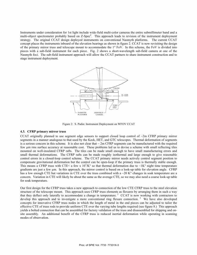
Instruments under consideration for 1st light include wide-field multi-color cameras the entire submillimeter band and a multi-object spectrometer probably based on Z-Spec4. This approach leads to revision of the instrument deployment strategy. The original CCAT design deployed instruments on conventional Nasmyth platforms. The current CCAT concept places the instruments inboard of the elevation bearings as shown in figure 2. CCAT is now revisiting the design of the primary mirror truss and telescope mount to accommodate the 1° FoV. In this scheme, the FoV is divided into pieces with a sub-field instrument for each piece. Fig. 2 shows a short-wavelength sub-field camera at one of the Nasmyth foci. The sub-field instrument approach will allow the CCAT partners to share instrument construction and to stage instrument deployment.
Figure 2: S. Padin: Instrument Deployment on WFOV CCAT
4.3. CFRP primary mirror truss CCAT originally planned to use segment edge sensors to support closed loop control of ~2m CFRP primary mirror segments in a manner analogous to that used by the Keck, HET, and GTC telescopes. Thermal deformation of segments is a serious concern in this scheme. It is also not clear that ~ 2m CFRP segments can be manufactured with the required few µm rms surface accuracy at reasonable cost. These problems led us to devise a scheme with small reflecting tiles mounted on well-insulated CFRP rafts. The tiles can be made small enough to have small manufacturing errors and small thermal deformations. The CFRP rafts can be made roughly isothermal and large enough to give reasonable control errors in a closed-loop control scheme. The CCAT primary mirror needs actively control segment position to compensate gravitational deformation but the control can be open-loop if the primary truss is thermally stable enough. This means a CFRP truss with CTE< a few x 107/K° so that thermal deformation due to ~1K° night time temperature gradients are just a few µm. In this approach, the mirror control is based on a look-up table for elevation angle. CFRP has a low enough CTE but variations in CTE over the truss combined with a ~20 K° changes in soak temperature are a concern. Variation in CTE will likely be about the same as the average CTE, so we may also need a coarse look-up table for soak temperature. Our first design for the CFRP truss takes a new approach to connection of the low CTE CFRP truss to the steel elevation structure of the telescope mount. This approach uses CFRP truss elements as flexures by arranging them in such a way that they deflect only laterally to accommodate a change in temperature. 2 CCAT is now working with contractors to develop this approach and to investigate a more conventional ring flexure connection. 3 We have also developed concepts for innovative CFRP truss nodes in which the length of metal in the end pieces can be adjusted to tailor the effective CTE of truss rods to provide uniform CTE over the varying tube lengths required (see figure 8.) This approach yields a bolted connection that can be assembled for factory validation of the truss and disassembled for shipping and on-site assembly. An additional benefit of the CFRP truss is reduced inertial deformation while operating in scanning modes of observation.
Proc. of SPIE Vol. 7733 77331X-3

The CFRP truss is challenging, and three study contracts have been let, one for the tipping structure design, one for CFRP truss concepts, and one for evaluation of CFRP rods and nodes for the truss. Additional details regarding the studies are provided below.
Figure 3: Two Alternate Designs for Attachment of CFRP Truss: Orange region is steel elevation structure of mount, Remainder of truss is CFRP tubes: L. uses Tubes as Flexures, R. Post and Ring Flexures (D. Woody)
4.4. Raft type PM segments A key component of the Universities of Cologne and Bonn joining CCAT was the funding by the government of Northwest Rhine Westphalia of a R&D contract with Vertex Antennentechnik to study primary mirror segments. CCAT initially considered three technologies, CFRP/Al honeycomb sandwich panels (Composite Mirror Associates, fused lightweight borosilicate glass panels (ITT, Rochester, NY), and SiC segments (Xinetics, Devens, MA). Of these three technologies, the CFRP sandwich panels appeared the most promising, but thermal deformations and cost are likely too large. Work at Caltech 4 and Vertex Antennentechnik has led to a concept with small tiles on SFRP rafts. K The basic scheme is shown in figure 4.
Figure 4: Sample CCAT PM Segment: Green is CFRP raft with 9 tiles shown forming reflective surface.
Proc. of SPIE Vol. 7733 77331X-4
The tiles might be CFRP with Al honeycomb core, CFRP with CFRP core, machined Al, or electro-deposited Ni. The tiles are mounted with manual adjusters that allow some control of low order figure errors. Each segment will be set up on a coordinate measuring machine at the CCAT site prior to installation in the primary. The raft structures below the tiles will be insulated to reduce thermal deformation. This will provide a stable location for segment to segment displacement sensors in the event that closed-loop control is implemented. Segments are attached to the truss with three ball-screw actuators.
4.5. Instrumentation
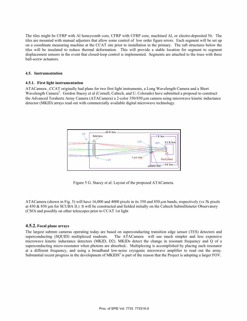
4.5.1. First light instrumentation ATACamera...CCAT originally had plans for two first light instruments, a Long Wavelength Camera and a Short Wavelength Camera5. Gordon Stacey et al (Cornell, Caltech, and U. Colorado) have submitted a proposal to construct the Advanced Terahertz Array Camera (ATACamera) a 2-color 350/850 μm camera using microwave kinetic inductance detector (MKID) arrays read out with commercially available digital microwave technology.
Figure 5 G. Stacey et al: Layout of the proposed ATACamera.
ATACamera (shown in Fig. 5) will have 16,000 and 4000 pixels in its 350 and 850 μm bands, respectively (vs 5k pixels at 450 & 850 µm for SCUBA II.) It will be constructed and fielded initially on the Caltech Submillimeter Observatory (CSO) and possibly on other telescopes prior to CCAT 1st light
4.5.2. Focal plane arrays The largest submm cameras operating today are based on superconducting transition edge sensor (TES) detectors and superconducting (SQUID) multiplexed readouts. The ATACamera will use much simpler and less expensive microwave kinetic inductance detectors (MKID, D2). MKIDs detect the change in resonant frequency and Q of a superconducting micro-resonator when photons are absorbed.. Multiplexing is accomplished by placing each resonator at a different frequency, and using a broadband low-noise cryogenic microwave amplifier to read out the array. Substantial recent progress in the development of MKIDS5 is part of the reason that the Project is adopting a larger FOV.
Proc. of SPIE Vol. 7733 77331X-5
5. STUDY CONTRACTS IN PROGRESS CCAT has several funded studies looking at technical issues in major telescope subsystems. Among these are studies of the primary mirror optics, CFRP structures, CFRP truss design, the design of the telescope mount, and the sensing and control of the primary mirror.
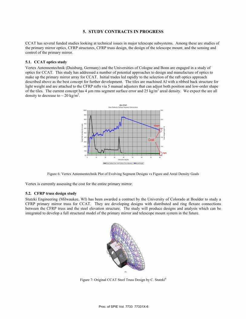
5.1. CCAT optics study Vertex Antennentechnik (Duisburg, Germany) and the Universities of Cologne and Bonn are engaged in a study of optics for CCAT. This study has addressed a number of potential approaches to design and manufacture of optics to make up the primary mirror array for CCAT. Initial trades led rapidly to the selection of the raft optics approach described above as the best concept for further development. The tiles are machined Al with a ribbed back structure for light weight and are attached to the CFRP rafts via 5 manual adjusters that can adjust both position and low-order shape of the tiles. The current concept has 4 µm rms segment surface error and 25 kg/m2 areal density. We expect the are all density to decrease to ~ 20 kg/m2.
Figure 6: Vertex Antennentechnik Plot of Evolving Segment Designs vs Figure and Areal Density Goals Vertex is currently assessing the cost for the entire primary mirror.
5.2. CFRP truss design study Stutzki Engineering (Milwaukee, WI) has been awarded a contract by the University of Colorado at Boulder to study a CFRP primary mirror truss for CCAT. They are developing designs with distributed and ring flexure connections between the CFRP truss and the steel elevation structure. The study will produce designs and analysis which can be integrated to develop a full structural model of the primary mirror and telescope mount system in the future.
Figure 7: Original CCAT Steel Truss Design by C. Stutzki6
Proc. of SPIE Vol. 7733 77331X-6

5.3. Composite structures study ATK Composite Optics Inc. (San Diego, CA) was awarded a contract for study of CFRP truss rods and joint designs for CCAT. The objective is to identify designs and manufacturing processes which meet both technical and cost requirements. Their analysis will provide properties for CFRP truss rods and joints which will be included in the Stutzki truss model analysis.
Figure 8: D. Woody design of a hybrid steel/Invar/CFRP Truss Node Connector
5.4. Telescope mount study (Contractor TBD) At this time, a source has not yet been selected for study of the CCAT mount/truss interface. The award of this study is anticipated for June of 2010. The contractor will be responsible for modification of the existing CCAT mount design to accommodate 1 degree FOV instruments. This redesign will include a larger tertiary and 3 m diameter elevation bearings. Figure 9 shows an initial concept for the modified mount. In this case the truss is attached using a ring of blade flexures positioned to minimize gravity deformation.
Figure 9: Concept for CFRP Truss Supported by Ring of Blade Flexures
5.5. Control system study A study of options for the CCAT Control System was has been completed.7 This study reviewed recent trends in astronomical observatory control system architectures and developed an initial set of top-level requirements for the CCAT control system. The study recommends using the ALMA common software as a top layer with LabVIEW as the interface to hardware devices.
Proc. of SPIE Vol. 7733 77331X-7

5.6. CompoVanguard Cocontracts for at better undother was an the first SBIRthe resultingmodels corre~0.8 meters apoints to a spoints had diabove the paconfigurationadjustment pwere not wel
Fi
osite Segment omposites (Sastudies of comerstanding the investigation R program. Th samples was
ected in pursuiacross the flatsstiff support suifferential scre
anel near the cn was ~ 1 µm process. The loll correlated wi
igure 10: Unidire
Studies an Diego, CA)mposite optics a
internal mechof how well th
he approach invcompared wit
it of better pres from a previourface made oews adjusters acenter of curva
level. The teocation of the ith the figure ch
Figure
ectional CFRP c
) were awardeapplicable to C
hanisms that cahe figure can bvolved makingth FEM predic
edictive modelious JPL prograf several layeras shown in Fiature. Tests inest optic was imactuators prevhanges that cou
10: Schematic o
coupons fabricate
ed two NASA/CCAT and futuause the shape be recovered byg test panels wictions and imping for CFRP
am (Precision Srs of CFRP/Aligure 10. The
ndicated that thmproved from
vented optimal uld be induced
of 0.8 m Panel on
ed for calibration
/JPL Small Buure flight progra
of molded CFy warping. Figith a completelprovements inoptics. The s
Segmented Refl honeycomb s
e panel was mehe measuremen
m about 20 µm adjustment of
d by the actuato
n 5 figure adjust
n/validation of c
usiness Innovaams. One of thRP optics to cgure 10 shows ly unidirection
n properties anecond SBIR uflector.) This pstructural paneeasured using nt repeatabilityRMS to abou
f panel figure aors.
ters
composite model
ative Researchhese studies wahange on releasamples fabrical layup. The
nd assumptionsused a hexagonpanel was attacels. The 5 atta laser tracker
y of the trackeut 10 µm RMSas some surfac
ling software
h (SBIR) as aimed ase. The cated for shape of s for the nal panel ched at 5 tachment r located er in this S via the e shapes
Proc. of SPIE Vol. 7733 77331X-8

5.7. JPL segment sensing and control study The look-up table control approach may not be adequate for operation at the shortest submm wavelengths, so the Advanced Optical Systems group at NASA/JPL has been developing a closed-loop segment sensing and control model for CCAT8,9. This uses optical edge sensors mounted on the segment rafts. The sensor has a CCD or quad cell on a segment and a collimated light source on the adjacent segment. The CCAT model includes all 6 rigid-body degrees of freedom for each segment, and ultimately will include thermal deformations of the segments. Results to date show that the surface can be controlled to a few µm rms provided that sensor mount deformations can be kept below 1 µm rms. Continuing studies will explore different sensor configurations. 5.8: Primary Mirror Alignment Calibration Sensor JPL has been studying the application of submillimeter detector arrays to interferometers suitable for measuring CCAT wavefront error. Their recent work investigates an application of a common-path pupil-plane interferometer that is a scanning version of the Zernicke/Dicke phase contrast interferometer.10
6. PLANS Over the next year CCAT has plans for a number of studies that will serve to reduce risk and support development of CCAT design concepts. These studies include:
• Geotechnical Survey: Test boring and analysis to determine bearing strata in support of foundation design and dynamic control modeling
• Road Design: Design of modifications to the access road from Paso de Jama to the Chajnantor summit. Required to transport materials and equipment for construction and operations support
• Foundation Design: Conceptual design and modeling of telescope foundation to support cost and performance assessment.
• Dome Structures Design Study: A study to apply factory made geodesic type structures to the CCAT Calotte dome. Intended to lower cost and simplify on-site construction.
• Dome Mechanisms: Additional design and analysis of concepts for azimuth and Calotte rotation of dome and shutter mechanisms.
• PM Detailed Truss Design: Study to follow current study of CFRP truss. More detailed design following trade selection of approach.
• PM Segment Raft Design: Trade study between alternate approaches to CFRP mirror raft design and additional design detail of chosen design.
• PM Tile Manufacturing Studies: Studies of alternate approaches to tile fabrication including machining, electro deposition, composite molding, etc.
• Segment Sensor Development: Investigation of sensor types for segment-to-segment displacement and angle sensors.
• Integrated Optics/Control Study: Extension of current segment sensing and control studies to incorporate truss designs, FEM, control algorithms to assess PM performance
• M2 & M3 Optics Study: Investigation of application of PM segment designs to M2 and M3 including support structures, actuation, alignment, etc.
• M2 & M3 Mechanisms Study: Study of M2 Hexapod and M3 turntable systems • Mount Detailed Concept Development and Analysis: Builds on this year's Mount Study and provides integrated
design and FEM for truss, optics, mount, foundation with performance assessment • Calibration Interferometer Study: Development of proof of concept design for submm interferometer used for
segment alignment, builds on CSO and previous studies. • Various other studies: Other studies to investigate cost and technical risk for remaining subsystems, update
CCAT cost estimate, study integration and assembly, further development of control systems hardware/software concepts, etc.
Proc. of SPIE Vol. 7733 77331X-9

Additional CCAT Papers at SPIE, San Diego: The following are other papers related to CCAT presented at the 2010 Astronomical Telescopes and Instrumentation Conference:
Wavefront controls for a large submillimeter-wave observatory Paper 7733-77 Author(s): David C. Redding, John Z. Lou, Andrew Kissil, Scott A. Basinger, Jet Propulsion Lab. (United States)
Modeling a large submillimeter-wave observatory Paper 7733-74 Author(s): John Z. Lou, David C. Redding, Andrew Kissil, Scott A. Basinger, Jet Propulsion Lab. (United States)
CFRP truss for the CCAT 25m diameter submillimeter-wave telescope Paper 7733-79 Author(s): David P. Woody, Stephen Padin, California Institute of Technology (United States); Thomas A. Sebring, Cornell Univ. (United States)
The Cornell Caltech Atacama Telescope: progress and plans 2010 (Invited Paper) Paper 7733-65 Author(s): Thomas A. Sebring, Cornell Univ. (United States)
CCAT optics Paper 7733-180 Author(s): Stephen Padin, Matthew I. Hollister, Simon J. E. Radford, Jack Sayers, David P. Woody, Jonas Zmuidzinas, California Institute of Technology (United States); German Cortes-Medellin, Thomas A. Sebring, Gordon J. Stacey, Cornell Univ. (United States)
Choosing a control system for CCAT Paper 7740-82 Author(s): David L. Terrett, Patrick T. Wallace, Rutherford Appleton Lab. (United Kingdom); Alan Bridger, Dennis Kelly, UK Astronomy Technology Ctr. (United Kingdom)
Submillimeter pupil plane wavefront sensing Paper 7741-30 of Conference 7741 Date: Wednesday, 30 June 2010 Author(s): Eugene Serabyn, J. Kent Wallace, Jet Propulsion Lab. (United States)
Advanced resonator designs for far-infrared astrophysics with MKIDs Paper 7741-24 of Conference 7741 Date: Wednesday, 30 June 2010 Author(s): Omid Noroozian, California Institute of Technology (United States); Peter K. Day, Jet Propulsion Lab. (United States); Byeong-Ho Eom, California Institute of Technology (United States); Henry G. LeDuc, Jet Propulsion Lab. (United States); Jiansong Gao, National Institute of Standards and Technology (United States); Juan M. Bueno, Jet Propulsion Lab. (United States); Jonas Zmuidzinas, California Institute of Technology (United States)
7. Summary The CCAT Project has made substantial progress and is addressing the highest technical risk areas of the telescope subsystems. Changes in concepts have been made in the areas where analysis revealed performance shortfalls and where opportunities to improve the efficacy of the telescope have been identified. Over the next three years, CCAT expect to retire the substantial majority of technical risk and to initiate the development of the observatory.
Proc. of SPIE Vol. 7733 77331X-10

REFERENCES
[1] Padin, S, Hollister, M.I., Radford, S.J.E., Sayers, J., Woody, D.P, Zmuidzinas, J., Cortes-Medellin, G, Sebring, T.A., Stacey, G.J., “CCAT optics”, Astronomical Telescopes and Instrumentation 2010, paper 7733-180 (to be published). [2] Woody, D.P., Padin, S., Sebring, T.A., “CFRP truss for the CCAT 25m diameter submillimeter-wave telescope”, Astronomical Telescopes and Instrumentation 2010, paper 7733-79 (to be published). [3] Stutzki, C.L., Tamai, H., Sebring, T.A., “Design concepts for primary mirror support structures of large telescopes for optical and submillimeter astronomy”, Ground-based and Airborne Telescopes, Proc. SPIE 7012 (to be published). [4] Padin, S., “Considerations for a Highly Segmented Mirror”, Applied Optics, vol. 42, no. 16 (2003). [5] Stacey, G. L. et al., “Instrumentation for the CCAT telescope,” Proc. SPIE 6275, 62751G (2006). [6] Schlaerth, J.,A., et al., “MKID multicolor array status and results from DemoCam”, Astronomical Telescopes and Instrumentation 2010, paper 7741-8 (to be published). [7] Terrett, D.L., Wallace, P.T., Bridger, A., Kelly, D., “Choosing a control system for CCAT”, Astronomical Telescopes and Instrumentation 2010, paper 7740-82 (to be published). [8] Redding, D.C., Lou, J.Z., Kissil, A., Basinger, S.A., “Wavefront controls for a large submillimeter-wave observatory”, Astronomical Telescopes and Instrumentation 2010, paper 7733-77 (to be published). [9] Lou, J.Z., Redding, D.C., Killis, A., Basinger, S.A., “Modeling a large submillimeter-wave observatory”, Astronomical Telescopes and Instrumentation 2010, paper 7733-74 (to be published). [10] Serabyn, E., Wallace, J.K., “Submillimeter pupil plane wavefront sensing”, Astronomical Telescopes and Instrumentation 2010, paper 7741-30 (to be published).
Proc. of SPIE Vol. 7733 77331X-11