THE CONVENTION CENTRE DUBLIN -...
7
DESCRIPTION OF BUILDING L Located in Dublin’s Spencer Dock and overlooking the River Liffey, The Convention Centre Dublin (The CCD) project opened to the public last September 2010. The project is a Public Private Partnership (PPP) project initiated by the Irish State. The PPP Company is a joint venture between the Spencer Dock Development Company as developers, Construction Management Partnership (CMP) as Design and Build Contractors and ‘The CCD’ as operators. O’Connor Sutton Cronin & Associates Consulting Engineers (OCSC) acted as Civil & Structural Engineers for the project, working directly for the Contractor under a Design and Build Contract. EXPLANATION OF DEVELOPMENT Key Milestone Dates: • Architect first appointed 1997 • OPW Tender issued December 2004 • PPP Co. Tender submission May 2005 • Preferred bidder appointment December 2005 • Design Team Tender Documents December 2006 • Formal Contract signing April 2007 • Start on site (Enabling works) November 2006 • Programme duration (excluding enabling works 36+1 mths. • Practical Completion 5th May 2010 • Services Commencement 5th August 2010 • Opening Date 7th September 2010 Ken Moriarty DIRECTOR B.Sc. (Eng.), Dip. Struct. Eng., C.Eng., M.I.E.I., M.I.Struct. E., Eur. Ing. Eddie Lyons SENIOR PROJECT ENGINEER B.E., C.Eng, M.I.E.I., M.I. Struct. E. page 1 THE CONVENTION CENTRE DUBLIN O’Connor Sutton Cronin & Associates Multidisciplinary Consulting Engineers 19 th April 2011 Plate 2: Architects 3-D Impression Plate 1 (Nov 2009): View of Building from South Quays
Transcript of THE CONVENTION CENTRE DUBLIN -...

DESCRIPTION OF BUILDING
LLocated in Dublin’s Spencer Dock and overlooking the River Liffey, The Convention Centre Dublin (The CCD) project opened to the public
last September 2010.
The project is a Public Private Partnership (PPP) project initiated by the Irish State. The PPP Company is a joint venture between the Spencer
Dock Development Company as developers, Construction Management Partnership (CMP) as Design and Build Contractors and ‘The CCD’ as
operators.
O’Connor Sutton Cronin & Associates Consulting Engineers (OCSC) acted as Civil & Structural Engineers for the project, working directly for the
Contractor under a Design and Build Contract.
EXPLANATION OF DEVELOPMENTKey Milestone Dates:
• Architect first appointed 1997
• OPW Tender issued December 2004
• PPP Co. Tender submission May 2005
• Preferred bidder appointment December 2005
• Design Team Tender Documents December 2006
• Formal Contract signing April 2007
• Start on site (Enabling works) November 2006
• Programme duration (excluding enabling works 36+1 mths.
• Practical Completion 5th May 2010
• Services Commencement 5th August 2010
• Opening Date 7th September 2010
Ken MoriartyDIRECTOR
B.Sc. (Eng.), Dip. Struct.Eng., C.Eng., M.I.E.I.,M.I.Struct. E., Eur. Ing.
Eddie LyonsSENIOR PROJECT ENGINEER
B.E., C.Eng, M.I.E.I., M.I.Struct. E.
page 1
THE CONVENTION CENTRE DUBLIN
O’Connor Sutton Cronin & Associates
Multidisciplinary Consulting Engineers
19th April 2011
Plate 2: Architects 3-D Impression
Plate 1 (Nov 2009): View of Building from South Quays

CLIENT BRIEF
The Client brief for The
Convention Centre Dublin calls
for a 2000 seat world class
auditorium, a 2000 seat banquet
hall and a 1200 seat banquet hall,
along with numerous meeting
rooms and back of house facilities.
Due to the constricted size of the
site, the three primary function
spaces are stacked ‘vertically’ from
an architectural design perspective.
From basement level there are two
levels of car parking; a 45m x 60m
exhibition hall at ground level; a
35m x 47m exhibition hall at first
floor level and the 2000 seat
auditorium positioned on top with
public access from three separate
levels.
The Client brief also calls for the
building structure to be designed for
a 100 year design life for all
structural elements, with major
replaceable components (cladding)
being designed for a 40 year design
life.
The exhibition halls are designed for an imposed loading of 12.5Kn/sq m, the auditorium 7.5Kn/sq m and the remaining floors 6.0Kn/sq m, all in
accordance with the brief.
The Client tender documents for the project were issued in late 2004. At this point the PPP consortium came together to prepare their bid for
the project, which was submitted to the Client in May 2005. From reaching preferred bidder status in December 2005, the formal appointment
of the successful consortia was made on the 6th April 2007.
Due to the nature of the contract (lump sum/fixed price contract with very high potential LAD’s), the Brownfield nature of the site and the potential
archaeological risks with the site, the Design and Build Consortium elected to commence work on site in November 2006, at their own risk.
THE TEAM• Client The Office of Public Works (OPW)
• PPP Co. Spencer Dock Development Company Limited
• Operator ‘The CCD’
• Design & Build Contractor CMP
• Architect Kevin Roche John Dinkeloo Associates
• Structural Engineer O’Connor Sutton Cronin & Associates (OCSC)
• Services Engineer MacArdle McSweeney Associates
• Theatre Consultant Theatre Projects
• Geotechnical Consultant Byrne Looby Partners
• Steel Fabricators Fisher Engineering
During the height of the design and drawing process, OCSC had eleven full time staff working on the project which included one project director,
one specialist structural modelling engineer, four structural project engineers, three general arrangement (structural) draughtsmen and two RC
detailers. In addition to this there was part time input from the peer review director and also from our structural dynamics expert.
page 2
THE CONVENTION CENTRE DUBLIN

DESIGN DISCUSSIONSite Constraints / Building Layout
The site, approximately 150m x 75m in plan,
was extremely restricted on it’s four sides,
with a canal under refurbishment to the
west, Mayor Street re-construction/Light Rail
project under construction to the north, a newly
completed office building housing a large
corporate tenant to the east and North Wall
Quay, a very busy primary traffic route, to the
south.
From basement level there are two levels of car
parking/double height service corridor and
service yard; a 45m x 60m exhibition hall at
ground level; a 35m x 47m exhibition hall at first
floor level and the 2000 seat auditorium
positioned on top with public access from three
separate levels.
A ‘Van and Truck’ lift provides full access from
the basement service yard to the Level Two
Exhibition Hall and the Level Three Auditorium
Stage for a large
rigid van and the trailer from a full articulated
vehicle.
Ground Conditions / Basement Design
The Ground conditions on this Brownfield site varied across its 150m length, and are described as follows.
Through ground water monitoring the upper level for the ground water level on the site was determined to be circa 0.5m O.D., with a design level
set at 2.0m O.D.
Due to the variable nature of the ground conditions of the site, it was decided to found the building on Continuous Flight Auger (CFA) Concrete
Piles, of varying diameter. Following a detailed design/cost review of anti flotation anchors, these piles were also utilised as tension piles in both
the temporary and permanent works load cases.
From a design perspective the concrete ‘envelope’ to the basement structure was specified as 70% GGBS concrete. This greatly assisted in
achieving The CCD’s ‘carbon neutral’ goal, whilst also meeting the 100 year design life criteria and the requirement to provide resistance to
sulphates in the ground.
page 3
THE CONVENTION CENTRE DUBLIN
The ground conditions to the south of the site The ground conditions to the north of the site:Fill 0 - 4.0m (metres below ground) Fill 0 - 4.2m (below ground)
Soft black silt 4.0 - 5.5m Soft grey silt 4.2 - 4.7m
Fine sandy gravel 5.5 - 7.0m Medium dense coarse gravel 4.7 - 7.1m
Soft clayey peaty silt 7.0 - 13.0m Hard boulder clay 7.1 - 8.2m
Medium dense coarse gravel 13.0 - 15.5m Medium dense coarse gravel 8.2 - 8.5m
Very stiff boulder clay 15.5 - 21.6m Very hard boulder clay 8.5 - 20.8m
Strong limestone rock 21.6m Strong limestone rock 20.8m
Plate 3 (Jan 2007): Aerial View of Site with Secant Piling Works Ongoing

DESIGN DISCUSSIONBasement Construction
In order to construct the two level basement, a 600mm/900mm diameter secant
piled wall was formed from ground level around the perimeter of the site. This
wall was constructed to a depth below ground such that the ground water
infiltration into the site during the construction of the basement was minimized.
The wall was then capped with a structural RC capping beam, with the site then
excavated to a depth of 7.5m, with only localised ground water de-watering
required. Loadbearing 600mm, 900mm and 1050mm diameter CFA piles, using
70% GGBS concrete, were then cast, followed by the part(s) of the basement slab
required to form the bases for the two southern concrete cores, which were then
jump formed in readiness for early steelwork erection, whilst also providing access
for construction workers throughout the project.
Structural Steel Analysis Design
A structural steel solution was chosen primarily because of the long span/shallow
structural depth imposed on the project by virtue of meeting the Client brief and
also keeping within planning constraints for building height, but also for programme
reasons insofar as all of the elements were fabricated off site and brought to site
in a well managed and controlled sequence.
Due to the location of the auditorium at the top of the building and the
requirement for ‘column free’ spaces in the two exhibition halls, a
substantial number of the columns supporting the auditorium seating
frames were transferred at the level three floor, through multiple transfer
beams and trusses.
The structural stability for the building is derived from the two southern
RC cores, steel sway frame action of two main frames and also a braced
frame on the northern extremity of the building, along the fly-tower
elevation. The southern RC cores needed to be constructed before
steelwork erection began, and they also contain the main escape stairs
which provided important access for workers during construction.The
biggest challenge from a design perspective was to determine the
dynamic response of the structure to imposed loading, because of the
long span/shallow structural depth imposed on the project by virtue of
the brief, the planning constraints and the site constraints.
The entire structure of the building was modeled in a three dimensional finite element analysis model to determine this. The structural frame of
the Convention Centre was also then tendered as a 3D model to the steelwork subcontractor as opposed to the more traditional drawing route.
This allowed a reduced tendering period, early Contractor involvement and aided in the
overall iterative value engineering the steel frame between the designers and
contractors. Additionally, the structural model was used to quickly determine the
effect of different structural solutions, thus leading to a highly efficient and
cost effective structural solution.
The integration of services into the main structural frame played a big
role in the overall steelwork co-ordination/fabrication drawing process.
The whole building is highly serviced and the steel frame needed to
accommodate all of the building’s M&E services whilst staying within the
architectural constraints and the Client brief.
The structure’s steelwork is based around eight internal 800mm x 800mm
fabricated plate columns (carrying a maximum load of 40,000Kn) with steel trusses
(2.3m deep) spanning 22m between columns. Six of these columns extend up through
the two exposition halls and top out at the roof level of the auditorium.
The upper auditorium terrace seating is formed using a series of frames which are positioned at 2.5m
centers on a radius around the auditorium, each of which have long propped-cantilevers. A number of the columns
supporting these frames are transferred out at the Level three floor using trusses which also form the roof of the first floor exposition hall.
page 4
THE CONVENTION CENTRE DUBLIN
Plate 4 (Sept 2007): View from Office Block to North of Site, Showing Basement Works
Plate 5 (Aug 2008) : View from Inside Auditorium Looking North, Showing Steelwork Erection
Plate 6: Isometric View of OCSC 3-D Finite Element Analysis Model
DESIGN DISCUSSIONStructural Steel Analysis Design (cont.)
Forming the main structural support for the roof over the auditorium is the project’s
largest single steel element; a 160t 48m long roof truss. The 6.5m deep truss,
consisting of 24 individual pieces, was assembled in position, using two
temporary towers to support it until the entire truss was bolted into
position with its connecting steel members and secondary trusses.
The 24m clear span (5m clear height) underground service yard, to the
north of the site, also incorporates the foundation and transfer structure to
accommodate a 35 storey (155m high) privately owned hotel tower overhead. The
basement slab under the service yard, at 2.5m thick, was poured in two separate sections,
the larger of which is approximately 2450 cubic metres. At the time of pouring this it was the
largest single concrete pour in Ireland.
Steelwork Erection
Steel erection, which started in late 2007, began on the south side of the site
and progressed, in six phases, steadily northwards away from the two
southern concrete cores, with an average of two steelwork erection crews
working simultaneously. In order to assist in the steelwork erection process, the
Level 3 floor slab at mid height of the building was designed to be able to
support numerous different types of ‘man-lift’ cherry pickers, as opposed to
utilizing heavy mobile craneage throughout the project.
The use of ‘Comflor’ metal deck flooring throughout the building minimized the
volume of concrete required for the suspended floors, whilst also avoiding the
use of temporary propping to floor decking.
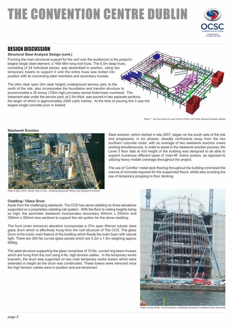
Cladding / Glass Drum
Aside from the challenging steelwork, The CCD has stone cladding on three elevations
supported on a proprietary cladding rail system. With the floor to ceiling heights being
so high, the perimeter steelwork incorporates secondary 400mm x 200mm and
350mm x 350mm box sections to support the rail system for the stone cladding.
The front (main entrance) elevation incorporates a 37m span Werner tubular steel
glass drum which is effectively hung from the roof structure of The CCD. The glass
Drum is the iconic main feature of the building which floods the main foyer with natural
light. There are 350 No curved glass panels which are 5.2m x 1.5m weighing approx
600kg.
The steel structure supporting the glass comprises of 10 No. curved ring beam trusses
which are hung from the roof using 4 No. high tension cables. In the temporary works
scenario, the drum was supported on two main temporary works towers which were
extended in height as the drum was constructed. These towers were removed once
the high tension cables were in position and pre-tensioned.
page 5
THE CONVENTION CENTRE DUBLIN
Plate 7 : Cut Out View of Level 4 from OCSC 3-D Finite Element Analysis Model
Plate 8 (Dec 2007): Aerial View of Site - Showing Basement Works and Steelwork Erection
Plate 9 (July 2008): Front Elevation of Building Showing Completed Drum Structure

DESIGN DISCUSSIONTemporary Works
Temporary works design, normally outside the remit of the project consulting
engineer, were taken on board by OCSC for several reasons, namely:
1. The fact that OCSC were best placed to carry out the temporary
works design, given the fact that the entire structure of the building
was modeled in a three dimensional finite element analysis model.
2. The tight programme along with potential LAD’s in excess of
€600k/week meant that OCSC were best placed to carry out the
design under the circumstances.
3. The nature of the temporary works design requirements was such
that in most cases, the critical load cases in design of permanent
elements was in fact the temporary works load cases. Interaction
with third party Design Consultants would have added significant
additional duration to the programme.
Several examples of the temporary works design are listed as
follows:
1. The design of the concrete stair/lift cores to
accommodate temporary ‘tie backs’ from the four
number tower cranes on the project. The cranes
were erected firstly as cantilevers from sub-
foundation level but they were lifted in height as the
building grew in height. To accommodate this, the
tower cranes were attached to the RC cores via
through-bolted steel SHS box section members.
The critical load case in the design of the cores was
the case where the building was fully clad but the
cranes were still operational and attached to the
cores.
2. The design of the level three floor slab to
accommodate numerous different types of ‘man-lift’
cherry pickers which were used by steelwork erection
crews to position and connect steelwork elements.
This was the critical load case for the design of the
slab(s).
3. The design of the propping to the ground floor insitu
podium slab(s) to accommodate mobile cranes, `
required for the erection of heavy steelwork elements
and elements of plant.
As noted previously, the contract was a design and build type
contract, where OCSC were employed directly by the Design
and Build Contractor. This type of contract, if entered into in
the correct frame of mind, can bring huge advantages to both
the D&B Client and the Consultant. In the case of The
Convention Centre Dublin, OCSC and the Contractor worked
very closely together, particularly in terms of the phasing of the
basement construction and the steelwork erection, to come up
with ways of saving time on the programme by changing, where
possible, the design of the structural frame. This would not
have been possible on a traditional tendered project.
page 6
THE CONVENTION CENTRE DUBLIN
Plate 11 (April 2010): View of Completed Front Elevation
Plate 10 (May 2008): View of South West RC Core, with Temporary Crane ‘Tie-Backs’ Attached

QUALITY CONTROLIn addition to OCSC’s own internal Quality Assurance reviews, the contract with the Client obliged the D&B Contractor to make milestone technical
submissions to the Client’s consultants, prior to the element in question being constructed on site. In practice this involved careful
Contractor/Design Team planning and coordination to ensure that the elements in question were given ‘Status A’ in advance of construction
commencing.
In parallel, the funding institution also nominated an independent Consulting Engineering practice to review the project from a funding ‘risk’
perspective. OCSC, in conjunction with the D&B Contractor, prepared a risk register which outlined the key risks in terms of the design and how
these risks were to be mitigated. In addition to and complimenting this, OCSC produced a ‘Basis of Design’ document which set the parameters
within which the Structural and Civil Design was to be carried out, how the 100 year design life was to be achieved, design codes to be followed,
floor loadings etc.
CONCLUSIONThe Convention Centre Dublin is the first state-owned, public-access building to be constructed since the foundation of the Irish State. It
officially opened to the public on 7th September 2010.
It is a benchmark in Irish Structural Engineering, not only as a result of overcoming the technical challenges presented as a result of placing a
full 2000 seater auditorium over two large exhibition halls, but also as a result of the (PPP) contract the construction of the building was executed
under and the methods used to tender the substantial steel frame package.
KEN MORIARTY Eddie Lyons
For O’Connor Sutton Cronin For O’Connor Sutton Cronin
page 7
THE CONVENTION CENTRE DUBLIN
Plate 12 (April 2010): View of Completed Auditorium, Taken From Stage